

Page 1
INSTRUCTION MANUAL
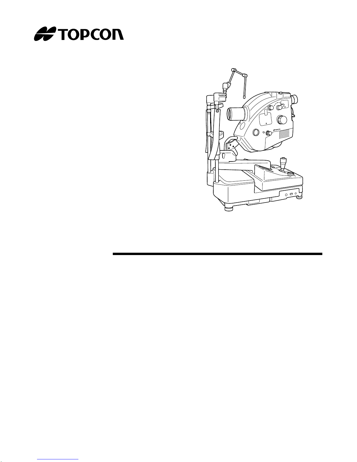
RETINAL CAMERA
TRC-50DX
TRC
-
50DX
Page 2

Page 3

1
INTRODUCTION
Thank you for purchasing the TOPCON TRC-50DX Retinal Camera.
This instrument is used to observe, take pictures or record pictures of the posterior segment of the eye through the pupil.
In Type IA of this instrument, the fluorescein angiography with indocyanine green is possible.
This instrument has the following features:
• This instrument assists the user in obtaining pictures of exceptional and stable quality.
• The instrument is easier to use and operate than previous models.
• A wide variety of optional accessories are available for diverse photographic and
imaging purposes.
This manual outlines the TRC-50DX Retinal Camera, including operating procedures,
troubleshooting, maintenance and cleaning.
Before using the instrument, carefully read the "DISPLAY FOR SAFE USE" and the
"SAFETY CAUTION S" to fam iliariz e yoursel f with the feat ures of th e TRC-50D X Retinal
Camera and to ensure that you operate it in an efficient and safe manner.
Always keep this Instruction Manual at hand.
CAUTIONS FOR USE
Basic caution
When taking a picture, m ake sur e that the patient keeps hi s/h er hand s aw ay fr om the mo va ble
parts to avoid possible injury.
Disposal
When disposing of TRC-50DX parts, follow the local regulations for disposal and recycling.
"Because prolonged intense light exposure can damage the retina, the use of the device for ocular
examination should not be unnecessarily prolonged, and the brightness setting should not exceed
what is needed to prov ide clea r visua liza tion of the target stru ctures . This de vice shoul d be used
with filters that eliminate UV radiation (<400nm) and, whenever possible, filters that eliminate
short-wavelength blue light (<420nm).
[Warning]
Be careful not to b ump the patient’s eyes or nose with the instrument dur ing
operation.
[The patient may be injured.]
This symbol is applicable for EU member countries only.
To avoid potential negative consequences for the environment and possibly human
health, this instrument should be disposed of (i) for EU member countries - in
accordance with WEEE (Directive on Waste Electrical and Electronic Equipment),
or (ii) for all other countries, in accordance with local disposal and recycling laws.
Page 4

The retinal exposure do se for a photoche mical haz ard is a product of the radiance and th e exposure time. If the value of radiance were r educed in hal f, twice the time would be neede d to reach
the maximum exposure limit.
While no acute optical radiation hazards have been identified for fundus cameras, it is recommended that the intensi ty of light directed into the patient's eye b e limited to the minimum level
which is necessary for diagnosis. Infants, aphakes an d persons with diseased eyes will be at
greater risk. The ri sk m ay al so be inc reas ed if the p e rso n b ein g ex am in ed has had any expo su re
with the same instrument or any other ophthalmic instrument using a visible light source during the
previous 24 hours. This will apply particularly if the eye has been exposed to retinal photography."
"Caution: Federal laws restricts this device to the sale by or on the order of a physician."
ENVIRONMENTAL CONDITIONS FOR USE
Temperature: 10°C ~ 40°C
Humidity: 30% ~ 75% (Non-condensing)
Air pressure: 700hPa ~ 1060hPa
STORAGE, USAGE PERIOD AND OTHERS
1. Environmental condi tio ns (with out packa ge)
Temperature: 10°C ~ 40°C
Humidity: 30% ~ 75% (Non-condensing)
Air pressure: 700hPa ~ 1060hPa
2. When storing the instrument, ensure that the following conditions are met:
(1) The instrument must not be splashed with water.
(2) Store the instrument away from envi ronments where a ir pressure, te mperatur e, humid-
ity, ventilation, sunlight, dust, salty/sulfurous air, etc. could cause damage.
(3) Do not store or transport the in strument on a s lanted or uneven surface or in an area
where it is subject to vibrations or instability.
(4) Do not store the instrument where chemicals are stored or gas is generated.
3. Normal life span of the instrument:
8 years from delivery providing regular maintenance is performed [TOPCON data]
ENVIRONMENTAL CONDITIONS FOR PACKAGING IN TRANSPORTATION
Temperature: -20°C ~ 50°C
Humidity: 10% ~ 95%
CHECKPOINTS FOR MAINTENANCE
1. Periodically inspect the instrument and its parts.
2. Before using the instrument after a long period of inactivity, make sure that it operates
safely and normally.
3. Be careful not to s tain the objective lens with fin gerprints, dirt, etc., as this will affect the
coatings and quality of pictures that the instrument takes.
4. When the instrument is not in use, cap the ob jecti ve lens and co ver the instrumen t with the
dust cover.
5. If the object ive lens is stained, clean it accor ding to "CLE ANING THE O BJECTIVE LENS"
on page 58 of this manual.
2
Page 5
DISPLAY FOR SAFE USE
To encourage safe and pro per use and to pr event injuri es to the operator and others or potential
damage to property, important messages are put on the instrument body and inserted in the
instruction manual.
We suggest that everyone understand the meaning of the following displays, icons and text before
reading the "SAFETY CAUTIONS" and observe all listed instructions.
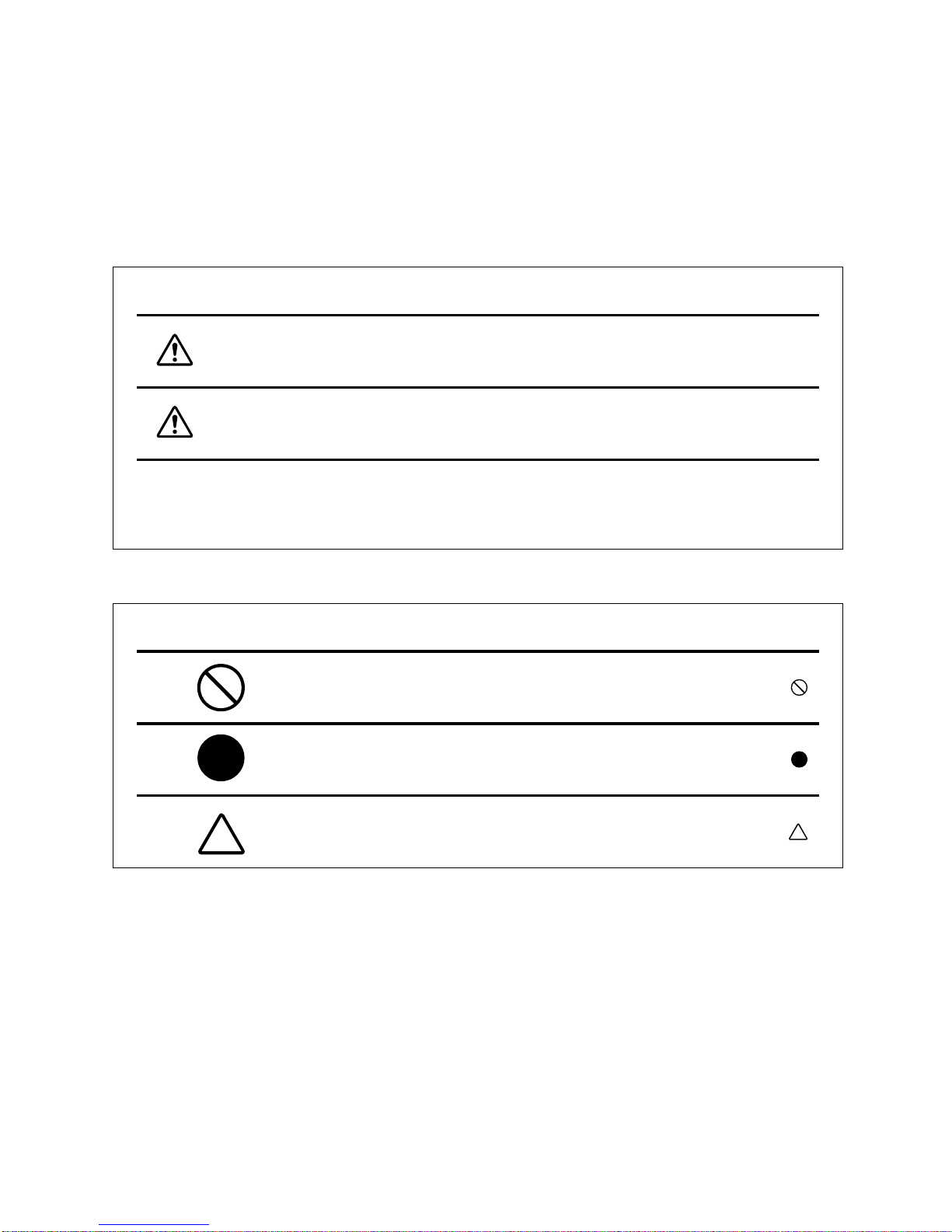
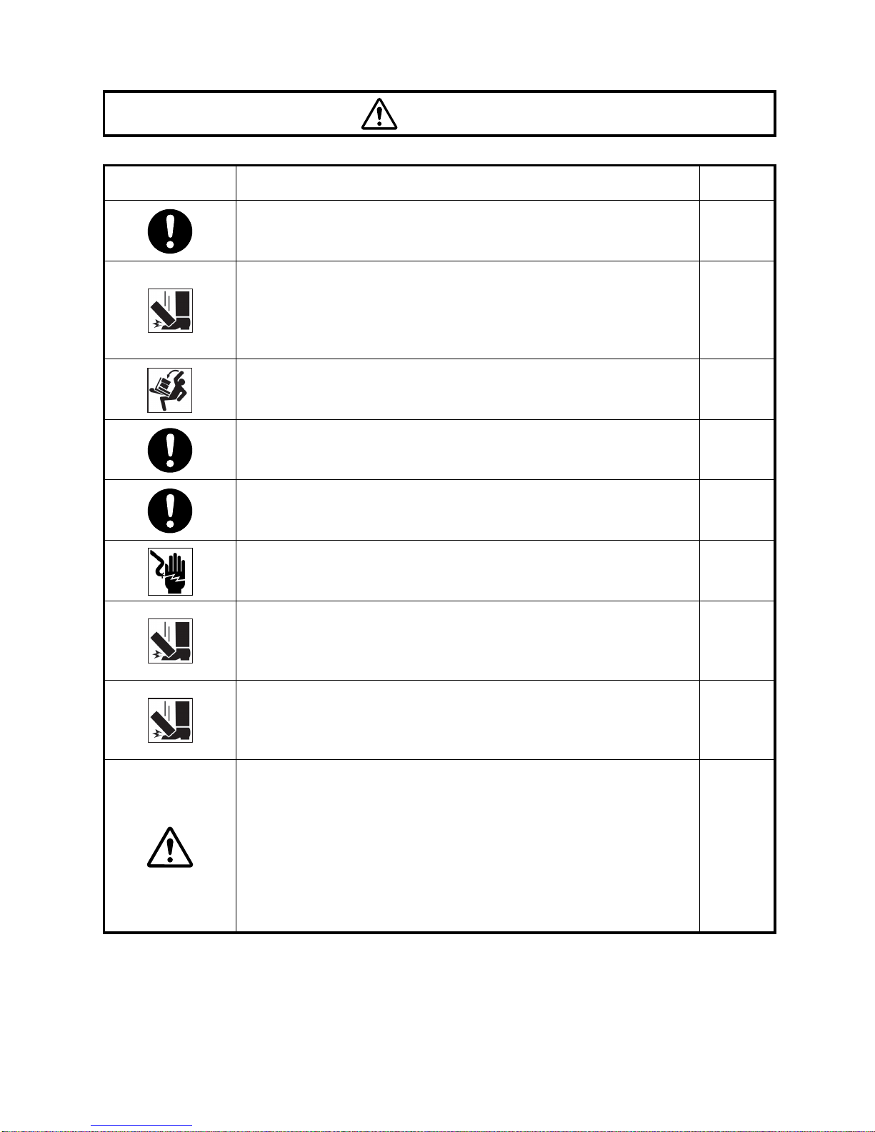
DISPLAYS
Display Meaning
ICONS
WARNING
CAUTION
• Injury refers to cuts, bruises, burns, electric shock, etc. which do not require hospitalization or extended medical treatment.
• Physical damage refers to extensive damage to the building, nearby equipment and/
or surrounding furnitur e.
Icon Meaning
Incorrect handling by ignoring this d isplay may lead to a r isk of
death or serious injury.
Incorrect handling by ignoring this display may lead to
personal injury or physical damage.
Prohibition.
Specific content is expressed with words or a picture near the
icon.
Mandatory Action
Specific content is expressed with words or a picture near the
icon.
Caution
Specific content is expressed with words or a picture near the
icon.
3
Page 6
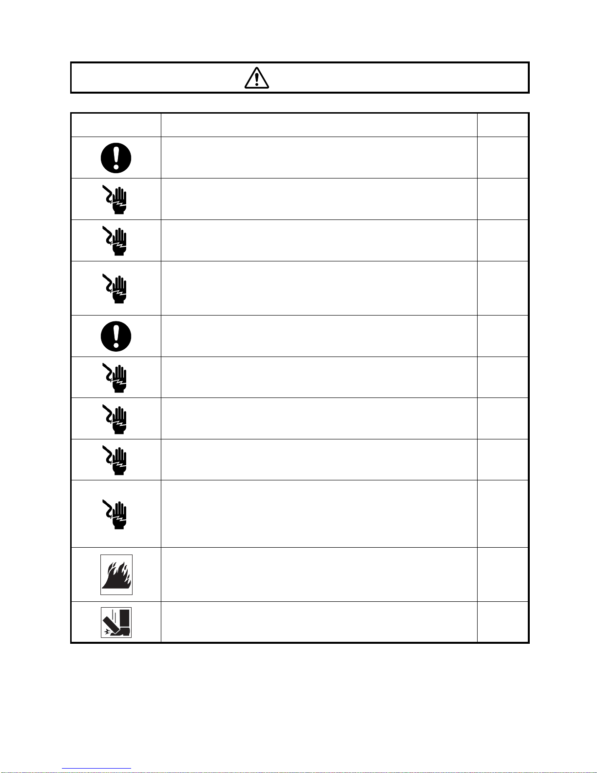
SAFETY CAUTIONS
Icon Prevention item Page
To avoid fire and ele ctric shock i n cas e of le akage, be su re to u se
a grounded receptacle. Do not connect to receptacles that are not
grounded.
WARNINGS
20
To avoid electric shock, do not attempt disassemblin g, rebuilding
and/or repairs on your own. Ask your dealer for repairs.
Do not remove the external covers from the main unit, chinrest unit
or power supply uni t except for the lamp house co ver. You may
receive an electric shock.
To avoid electric shock when replacing the fuse, be sure to unplug
the instrument before removing the fuse cover. Do not use
ungrounded outlets. Do not plug in the instrument without the fuse
cover.
To avoid fire in the ev ent of an instrument malfunction, use onl y
the fuses that are marked with the label at the side of the fuse
holder.
To avoid fire and electric shock, install the instrument in a dry
place free of water and other liquids.
To avoid fi re and elec tric shock, do not put cu ps or other containers with liquids near the instrument.
To avoid electric shock, do not insert metal objects into any vents
and/or slots.
46
46
57
57
-----
37, 39,
40
-----
Disconnect the power plug from the outlet before removing the
lamp house cover. Electric shock may occur if you remove the
lamp house cover without di sconnecting the power plug. Do not
connect the power plug to the outlet while the lamp house cover is
not set on the instrument.
To avoid fire in the event of an instrument malfunction, immediately turn OFF th e power switch and unplug the cable if you see
smoke coming from the instrument, etc. Ask your dealer for
repairs.
To avoid injury, remove the accessories of the UPPER mount
before carrying the instrument. The instrument may tip over.
4
-----
-----
62
Page 7
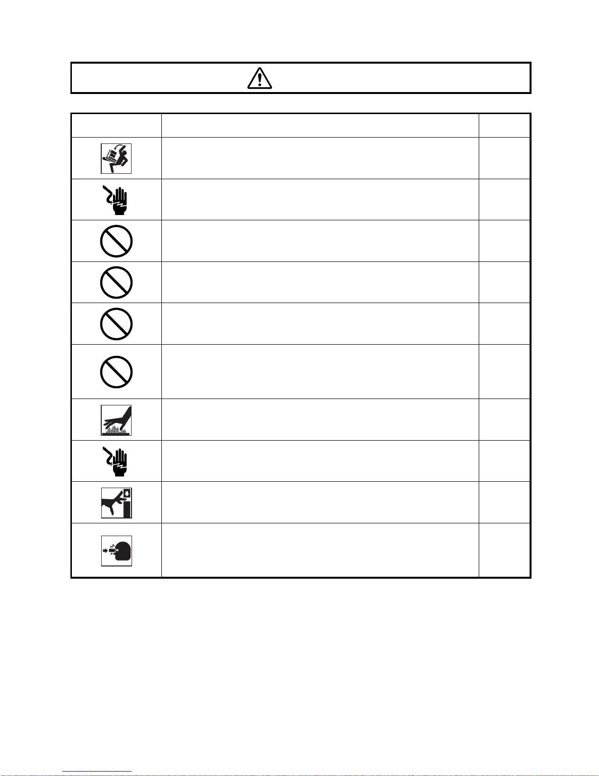
CAUTIONS
Icon Prevention item Page
To prevent damage and injuries, do not install the instrument on an
uneven, unsteady or sloped surface.
To avoid electric shock, do not handle the plugs with wet fingers. 20
To avoid discomfort or damage to the patient's eye, do not
brighten the illumination lamp more than necessary.
To avoid discomfort or damage to the patient's eye, do not make a
flash intensity level higher than necessary.
To avoid injury while inclining the instrument body, do not place
your fingers in to th e g ap b etwe en t he i ns trum ent body a nd t he 1st
arm.
To avoid injury while moving the instrument body, do not place
your fingers into the gap between the 1st/2nd arm and the chinrest
column.
*Please give proper instructions to the patient.
To avoid burns, do not replace the lamp with a new one immediately after it goes off. Allow time for it to cool.
53
32
32
32
32
54
To avoid electric shock, do n ot r ep lace t he x en on l am p wi th a new
one immediately after it goes off.
To avoid inju ry while moving the base, do not place yo ur fingers
into the gap between the instrument base and the power supply
unit.
Pay attention to the clear ance betwee n the object ive lens an d the
patient.
When the main body is moved, the objective lens may bump
against the patient's eye or nose inflicting a minor injury.
55
32
32
5
Page 8
CAUTIONS
Icon Prevention item Page
To prevent falls and in jury during tr ansportation of the instrument,
be sure to lock the base and arm by using the lock ing lev ers. This
will prevent the instrument from moving and sliding.
To avoid injury during carrying, be sure to hold the instrument body
at the bottom with two people. Carrying by one person may cause
backache or injury by falling. Holding at areas other than the bottom may also caus e pinched fingers and injury, as well as falling,
thereby causing damage to the instrument.
-----
-----
To avoid falli ng and in jury while moving the instrument on a r ol li ng
table, be sure to use an approved instrument table.
To avoid injury while moving the chinrest up and down, instruct the
patient to keep hands away from moving parts.
Be careful not to let the patient hold the column. His/her finger
may be pinched between the column and 1st/2nd arm causing
injury.
To avoid elec tric shock, be sure to turn the pow er switch off and
unplug the power cord before replacing the lamp.
Ensure that the 35 mm camera is installed firm ly by fastening the
35mm camera body locking lever.
If installed loosely, the camera may fall off, resulting in severe
damage to the unit and bodily injury.
When installing accessories, secure them firmly by fastening the
accessory locki ng lever.
If installed loosely, the accessories may f all off, leading to bodily
injury.
This instrument has been tested (with 100-120V/200-240V) and
found to comply with IEC60601- 1-2: 2001 .
This instrument radi ates radio frequency energy within standards
and may affect other devices in the vicinity.
If you have discovered that turning on/off the instrument affects
other devices, we recommend that you change its position, keep a
proper distance from other devices, or plug it into a different outlet.
Please consult your authorized dealer if you have any ad ditional
questions.
-----
30
30
54, 55
62
62
-----
6
Page 9

USAGE AND MAINTENANCE
USAGE
• The TRC-50DX Retinal Camera is an electric instrument for medical use. Use this
instrument under a doctor's guidance.
USER MAINTENANCE
To ensure the safety and performance of the instrument, all maintenance work,
unless specified in this manual, shall be conducted by trained service engineers.
The following maintenance tasks may be done by the user.
For details, see the relevant part of this manual.
Replacing lamps:
The illumination lamp and Xenon lamp may be replaced by the user. For details, see
"REPLACING THE ILLUMINATION LAMP" on page 54 and "REPLACING THE
XENON LAMP" on page 55.
Replacing fuses:
The fuses on the instrument body may be replaced by the user. For details, see
"REPLACING THE FUSE" on page 57.
Cleaning the objective lens:
The objective l ens may be cleaned by the user. For details, see "CLEANING THE
OBJECTIVE LENS" on page 60.
ESCAPE CLAUSES
• TOPCON shall not take any responsibility for damage due to fire, earthquakes, actions
by third persons and other accidents, or damage due to negligence and misuse by the
user and any use under unusual conditions.
• TOPCON shall not take any responsibility for damage derived from inability to properly
use this instrument, such as loss of business profit and suspension of business.
• TOPCON shall not take any res ponsibility for damage caus ed from using this instrument in a manner other than that described in this Instruction Manual.
• Diagnoses made shal l be the responsibilit y of pertaining doctors and TOPCON shall
not take any responsibility for the results of such diagnoses.
7
Page 10
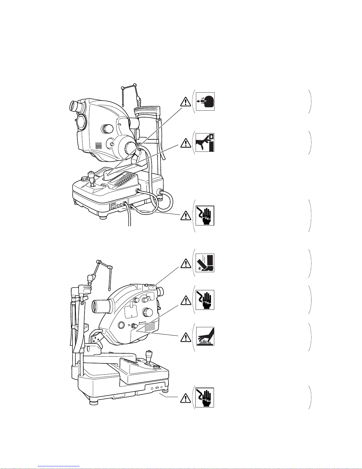
WARNING DISPLAYS AND POSITIONS
To ensure safety , this machin e provides warning displays.
Use the instrument corre ctly by observi ng the di splay instru ctions. If any of the fo llowing display lab els
are missing, cont act yo ur TOPCON dealer at the address li sted o n the b ack cover of t his man ual .
CAUTION
y To a void injury while operating the instru-
ment, be carefu l to preve nt you r han d from
being pinched by the movable parts.
CAUTION
y To avoid injury to the patient while operat-
ing the instrument, be careful not to hit his/
her face with the ins trument body.
WARNING
y Before replacing the fuse with a new one, to
avoid electric shock and fire, turn off the
power switch and remove the power cable
from the outlet. Be sure to use the correctly
rated fuse for replacement.
TRC
-
WARNING
y To avoid injury, remove the accessories of
the UPPER mount before carrying the
instrument. The instrument may tip over.
WARNING
y Before replacing the lamp unit with a new
one, turn off the power switch and remove
the power cable from the outlet to avoid
electric shock.
50DX
CAUTION
y To avoid burns, do not replace the lamp
with a new one immediately after it goes off
because it is still very hot and can cause
burns.
CAUTION
y To avoid electric shock, do not open the
covers. Ask your service personnel for
repairs.
8
Page 11

CONTENTS
INTRODUCTION ................................................................................................................1
CAUTIONS FOR USE ........................................................................................................1
ENVIRONMENTAL CONDITIONS FOR USE......................... ...... ...... ....... ...... ....... ...... ......2
STORAGE, USAGE PERIOD AND OTHERS.....................................................................2
ENVIRONMENTAL CONDITIONS FOR PACKAGING IN TRANSPORTATION.................2
CHECKPOINTS FOR MAINTENANCE..............................................................................2
DISPLAY FOR SAFE USE..................................................................................................3
SAFETY CAUTIONS ..........................................................................................................4
USAGE AND MAINTENANCE............................................................................................7
USAGE ...............................................................................................................................7
USER MAINTENANCE.......................................................................................................7
ESCAPE CLAUSES............................................................................................................7
WARNING DISPLAYS AND POSITIONS ...........................................................................8
NOMENCLATURE
COMPONENTS OF MAIN UNIT.......................................................................................12
COMPOSITION OF PARTS WHICH CONTACT WITH THE HUMAN BODY...................14
COMPONENTS OF BASE UNIT......................................................................................15
COMPONENTS ON CONTROL PANEL SCREEN...........................................................16
NAMES IN OPTICAL FINDER..........................................................................................18
STANDARD ACCESSORIES ...........................................................................................19
SETUP
CONNECTING THE POWER CORD ...............................................................................20
CONNECTING THE EXTERNAL DEVICE .......................................................................21
RESET FROM POWER SAVE STATE .............................................................................22
SETTING ON THE SET MENU DISPLAY........................................................................23
BASIC OPERATIONS
PREPARATION FOR PHOTOGRAPHY ...........................................................................28
PREPARATION OF THE PATIENT...................................................................................30
COLOR PHOTOGRAPHY ................................................................................................32
FAG PHOTOGRAPHY......................................................................................................37
ICG FLUORESCEIN PHOTOGRAPHY (ONLY IN TYPE IA)............................................39
RED FREE PHOTOGRAPHY WITH GREEN FILTER
(ONL Y IN RELEVANT PRODUCTS).................................................................................40
AUTO FLUO (AUTO FLUORESCENCE) PHOTOGRAPHY
(ONL Y IN RELEVANT PRODUCTS).................................................................................40
9
Page 12

OBJECTIVE OPERATIONS
PHOTOGRAPHY BY INCLINATION AND SWINGING.....................................................42
BLUE FILTER PHOTOGRAPHY.......................................................................................43
PHOTOGRAPHY WITH ALTERNATIVE FILTER (EXCLUDING TYPE IA).......................43
STEREO PHOTOGRAPHY ..............................................................................................44
INTERNAL FIXATION TARGET MOUNT (ONLY IN TYPE IA).........................................45
BEFORE REQUESTING SERVICE
TROUBLESHOOTING......................................................................................................46
ERROR CODE LIST.........................................................................................................49
SPECIFICATIONS AND PERFORMANCE
SPECIFICATIONS............................................................................................................50
ELECTRIC RATING..........................................................................................................50
SYSTEM CLASSIFICATION.............................................................................................51
DIMENSIONS AND WEIGHT ...........................................................................................51
PURPOSE OF USE..........................................................................................................51
OPERATION PRINCIPLE.................................................................................................52
MAINTENANCE
DAILY CHECKUPS...........................................................................................................53
ORDERING CONSUMABLES..........................................................................................53
MAINTENANCE BY THE DEALER ..................................................................................53
REPLACING THE ILLUMINATION LAMP ........................................................................54
REPLACING THE XENON LAMP ....................................................................................55
REPLACING THE FUSE ..................................................................................................57
REFILLING THE CHINREST TISSUE PAPER.................................................................58
THE FAG FLUORESCEIN FILTER...................................................................................58
CLEANING
CLEANING THE EXTERNAL COVER, CONTROL PANEL AND OTHERS.....................60
CLEANING THE PARTS WHICH COME INTO CONTACT WITH THE PATIENT ............60
CLEANING THE OBJECTIVE LENS................................................................................60
CLEANING THE LENS WHICH IS SEEN IN UPPER MOUNT ........................................61
OPTIONAL ACCESSORIES
OPTIONAL ACCESSORY MOUNTING/DETACHING METHODS...................................63
ACCESSORY LENS CLEANING METHODS...................................................................67
1× RELAY LENS ADAPTER OR-2 ...................................................................................68
TV RELAY LENS ADAPTER.............................................................................................69
10
Page 13

REFERENCE MATERIAL
SHAPE OF PLUG.............................................................................................................71
SYMBOL...........................................................................................................................71
USABLE AUTOMATIC INSTRUMENT TABLE .................................................................72
ELECTROMAGNETIC COMPATIBILITY ..........................................................................73
RELATION BETWEEN SETTING OF ILLUMINATION/FLA SH LEVEL
AND MAXIMUM RADIANCE..............................................................................................77
INFORMATION ABOUT THE OPTICAL RADIATION HAZARD
FOR THE USER....................................................................................................................78
11
Page 14
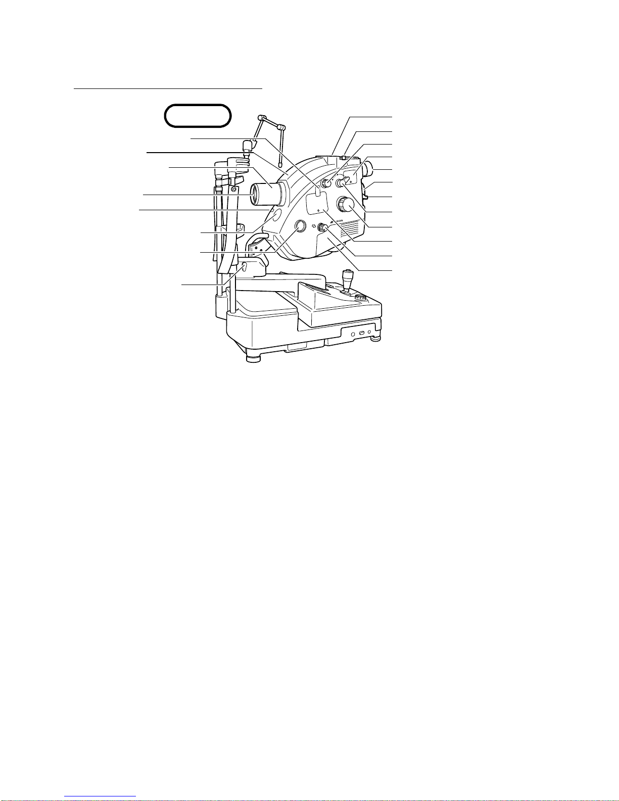
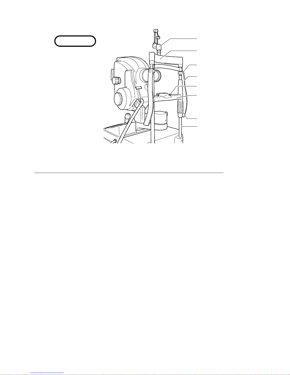
NOMENCLATURE
COMPONENTS OF MAIN UNIT
Main unit
Astigmatic correction knob
External Cover
Objective lens barrel
Objective lens
Cable holder
Internal fixation target mount
Internal fixation target mount
(TYPE IA with split lines)
Swing arm locking lever
TRC
-
50DX
UPPER mount
UPPER mount locking lever
Diopter compensation lens selector
Shading compensation cover
Optical finder
LOWER mount
LOWER mount locking lever
Angle changing lever
Focusing knob
Barrier filter cover
Filter switching knob
Lamp house cover
Angle changing lever........ ...................... 50°, 35° or 20° ma y be selected as the angle of cover-
age.
Diopter compensation lens selector.......Used to compensate the di optric power o f strong myo pia
and hyperopia in the patient and also used for ocular
anterior photography.
Filter switching knob...............................Changed for different kinds of photography.
UPPER mount ........................ ................ Optional accessories (different types of relay l enses) are
mounted here.
Internal fixation target mount..................Usable when the split lines are OFF. (Only in Type IA with
split lines)
Shading compensation cover .............. ...Open thi s cover when cleani ng the lens which i s seen in
the UPPER mount.
Astigmatic correction knob..................... Used when correcting the astigmatism degree of the
patient. (Only in relevant produc ts)
Internal fixation target mount......... ...... ...Th e internal fixat ion target can b e mounte d. (This c an be
installed as an optional accessory in Type IA (without
split lines), and as a standard a ccessory in Type IA (with
split lines).)
12
NOMENCLATURE
Page 15
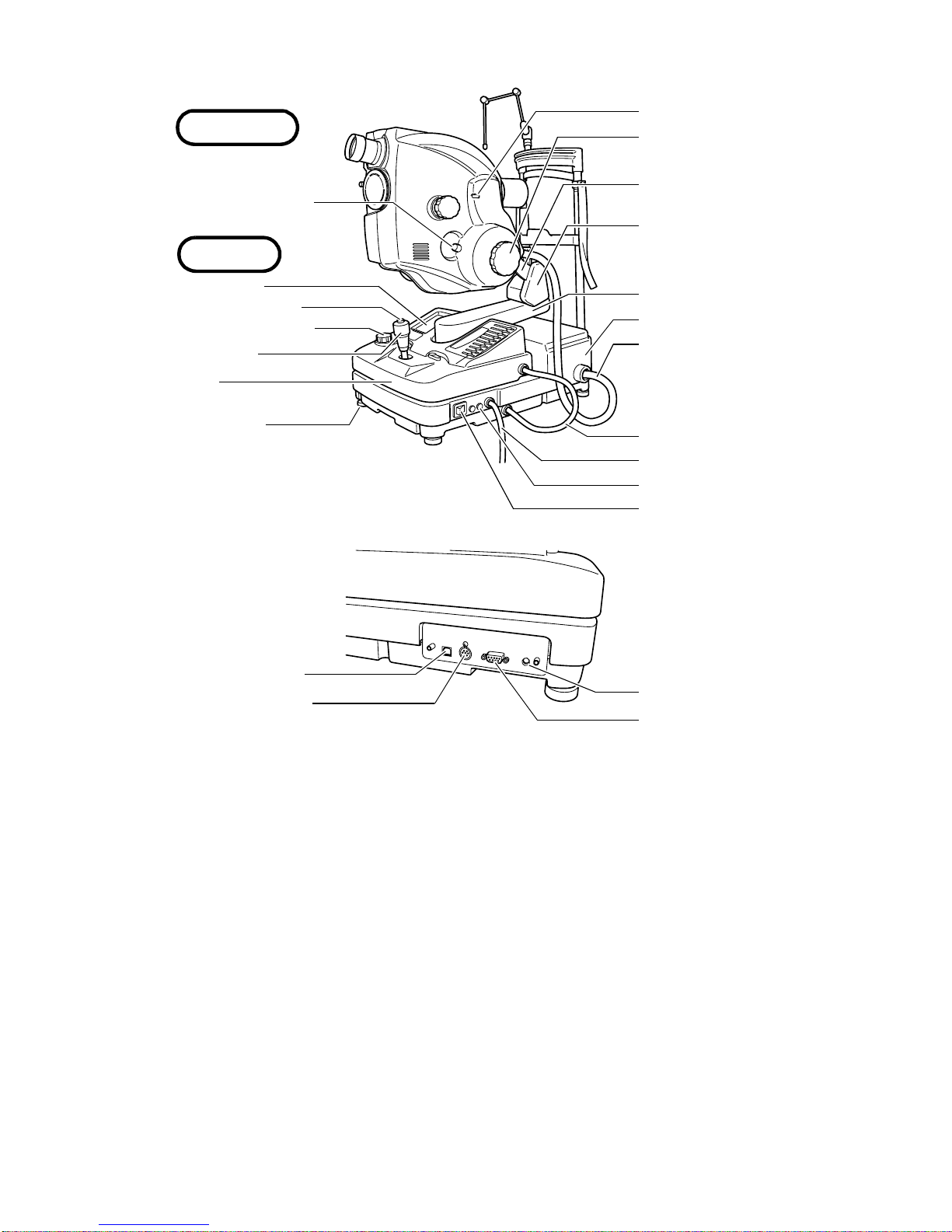
Tilting unit
Inclination brake knob
Base unit
"Horizontal" index window
Inclination handle
Inclination rail
2nd arm
Control panel
Photography switch
Illumination level knob
Control lever
Cover
Level adjuster
External connection terminal
USB terminal
DATA terminal
1st arm
Base
Main unit connecting cord
Base unit connecting cord
Power cord
Fuse holder
Power switch
DATA
CONTROL
TIMER
TIMER terminal
CONTROL terminal
Photography switch ........................ Press this switch, and the xenon lamp flashes and different
Inclination handle...........................Performs inclination in upper 15° and lower 10°.
Inclination brake knob....................Inclination is set to "free" or "lock" by turning this knob.
2nd arm..........................................Swings up to 30° to the right and left.
CONTROL terminal........................Used to connect to IMAGEnet.
DATA terminal ................................Used to communicate with IMAGEnet.
TIMER terminal ..............................Used to connect with the video timer.
USB terminal..................................Used to connect to IMAGEnet.
types of photography are possible.
13
NOMENCLATURE
Page 16
14
NOMENCLATURE
Headband...................Used when fixing the patient's head. (Only in relevant products)
COMPOSITION OF PARTS WHICH CONTACT THE HUMAN BODY
Forehead rest : Polyamide resin
Chinrest : Polyamide resin
Headband : Polyvinyl chloride resin
Chinrest adjusting knob : Polyacetal resin
Chinrest tissue pin : Polyamide resin
Chinrest tissue : Paper
Chinrest unit
External fixation target
Forehead rest
Canthus marker
Headband
Chinrest tissue pin
Chinrest
Chinrest adjusting knob
Column
Page 17
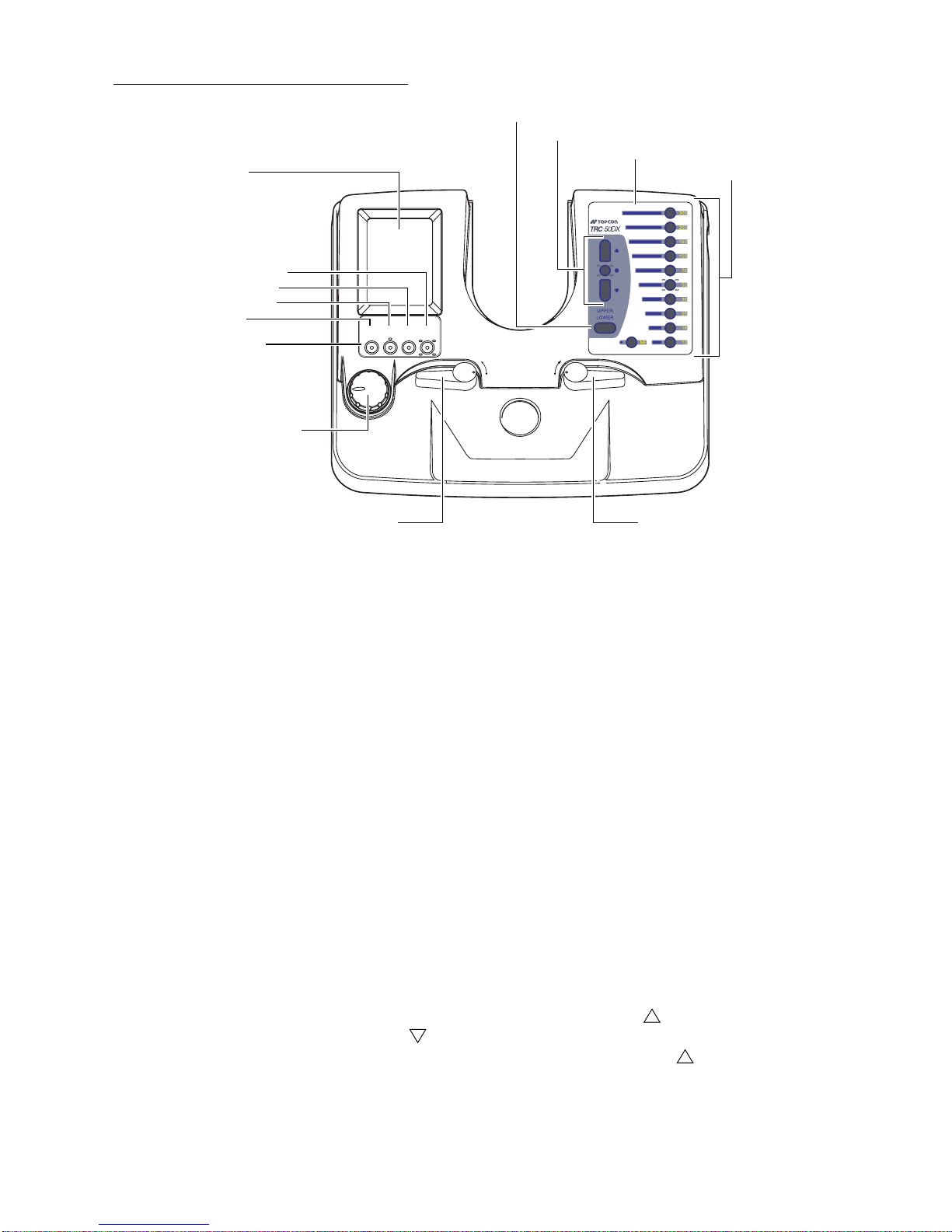
COMPONENTS OF BASE UNIT
Control panel
TIME (Timer) switch
Ba (Barrier) switch
Ex (exciter) switch
SPLIT switch
Operation panel
Illumination level knob
STEREO lever Base fixing lever
SPLIT
Ex
UPPER/LOWER selector switch
Flash correction switches
Flash selector panel
Flash selector switch
TIME
Ba
LOCK LOCK STEREO STEREO
FREE FREE FREE FREE
Control panel..................................On this touch panel, the set data are displayed and a variety of
setting is done.
Illumination level knob....................Adjusts the illumination level according to the patient's eye.
Ba (Barrier) switch..........................Sets the barrier fil ter. Press this switch again, and th e barrier
filter is removed.
TIME (Timer) switch......... ...... ....... .Press this s witc h, an d th e tim er s tarts. Pr ess i t a gai n, and the
timer stops.
Ex (exciter) switch ........... ..............Sets the ex citer filter. Press this sw itch again, a nd the exci ter
filter is removed.
SPLIT switch.................................. Sets the internal fixation target to "OFF". Press this switch,
and the split lines are set. Press this switch again, and the
split lines are removed. (Only in relevant products)
STEREO le ver................................ Us ed for stereo photography. Refer to "STEREO PHOTOG-
RAPHY" on page 44 for details.
Base fixing lever.............................Used to lock the base.
UPPER/LOWER selector switch ....When UPPER is selected, photography by the UPPER set
camera is possible.
When in POW ER SAVE mode , push this switch t o reset the
instrument.
Flash selector switch...................... Photography light intensity can be selected in 11 steps. NF
means no light emission from the xenon flash lamp.
Flash correction switches...............Increase or decrease the preset light intensity. (It can be
changed by 21 steps.) Press the
bu tton to increase i t or
the button to decrea se it. For example, when th e preset
light quantity is 36W·s, one press of the button changes the
setting to a value between 36W·s and 50W·s and turns on
both switches (36) and (50).
15
NOMENCLATURE
Page 18
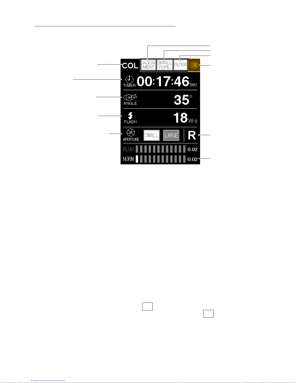
COMPONENTS ON CONTROL PANEL SCREEN
(
)
Setting operation display (Example of the photography mode color)
Photography mode indication
Timer ind i cation
Angle of coverage indication
FLASH (flash level) indication
ALIGNMENT switch
SMALL PUPIL switch
FILTER switch
Menu switch
APERTURE (photography aperture)
indication
Right/left detection
indication
Illumination level
indication
Photography mode in dication ... Indicates the currently set photography mode. The modes, "COL
(Color)", "GRE (Green)", "FA (FAG)", "F1, F2, AF (AUTO FLUO)"
and "IA (ICG fluorescein)" ("AF, IA" in use only in Type IA) are
changed by o perat ing "F ilter s witch ing kn ob" on t he ma in uni t, "Ex
switch" and "Ba switch".
ALIGNMENT switch ..................Turns on/off the alignment bright spot.
SMALL PUPIL switch................Changes the current mode to the microcoria mode.
FILT ER switc h ........................... Ba (barrier) fi lter or Ex (exciter) filter is set in the link operation
with the photography switch. When the link operation is OFF, it is
possible to take a picture as regarding the Ex (exciter) filter as the
blue filter.
Menu switch........ ......................Indicates the set menu. Wh ile the TIME switch is operating, th is
switch disappears on the screen to prevent a wrong operation.
Timer indication .........................Press the TIME (timer) switch on the base unit, and the timer
starts. Press the switch again, and the timer stops.
Angle of coverage indication.....Indicates the angle of co verage, w hich i s set by the a ngle chan g-
ing lever on the main unit.
FLASH (flash level) indication...Indi cates th e FLAS H (flas h level ), whic h is s et by the flas h selec -
tor switch and the flash correction switches on the base unit.
APERTURE ............... ............ ...By using the switch, it is po ssible to adjus t the f ocus easily
photography aperture
(increased depth of field). By using the switch, it is possible
SMALL
LARGE
to take a picture with low flas h level. This can be used in col or
photography and ICG fluorescein photography (only in Type IA).
Right/left detection indication ...."L" (left eye) or "R" (right eye) is indicated.
Illumination level indication .......Indicates the illumina tion level (halog en), which is set b y the illu-
mination level knob on the base unit.
16
NOMENCLATURE
Page 19
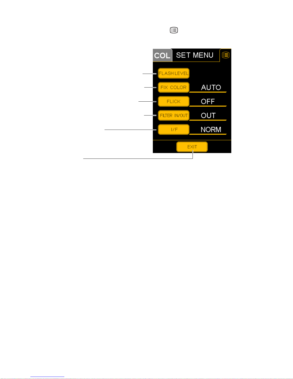
SET MENU display
Carries out a variety of settings. Press the MENU button on the setting operation display, and
"SET MENU" will be displayed. Refer to "SETTING ON THE SET MENU DISPLAY" on page 23.
FLASH LEVEL (Flash level standard setting)
FIX COLOR (External fixation color selection)
FLICK (External fixation blinking selection)
FILTER IN/OUT (Filter link operation method)
I/F (Interface selection)
EXIT switch
FLASH LEVEL (Flash level standard setting) .... Sets the flash intensity level standard value for
each photography mode.
FIX COLOR (External fixation color selection)... Selects the color of the external fixation lamp,
"AUTO" (automatic), "GREEN" or "RED".
FLICK (External fixation blinking selection)........ Selects the status of the external fixation lamp,
"ON" (blinking) or "OFF" (lighting)
FILTER IN/OUT (Filter link operation method)... Selects the link operation method for the photog-
raphy switch and Ba (barrier) filter.
I/F (Interface) switch........................................... Changes the interface.
EXIT switch ........................................................ Returns to the setting operation display.
17
NOMENCLATURE
Page 20
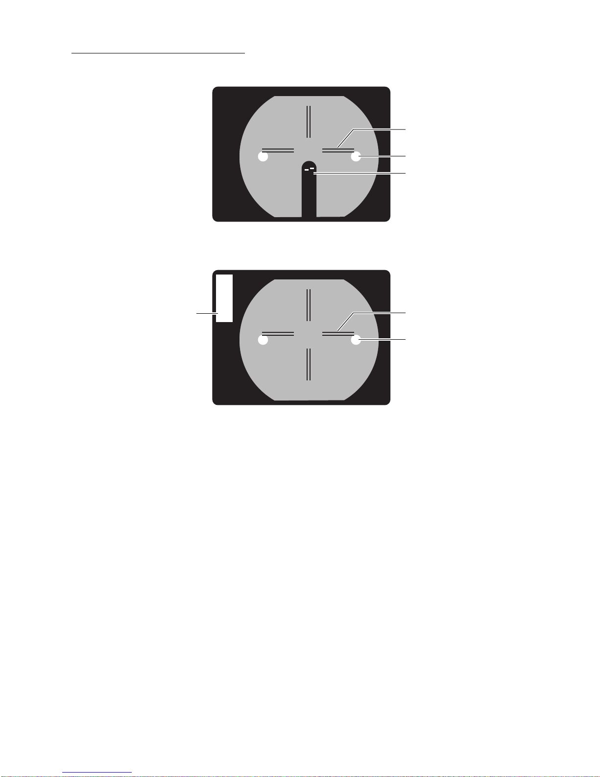
NAMES IN OPTICAL FINDER
00.00.0
TIMER
R 50
Reticles
Alignment bright spot
Split lines
"With split" type
Reticles
"Without split" type
Alignment bright spot
18
NOMENCLATURE
Page 21
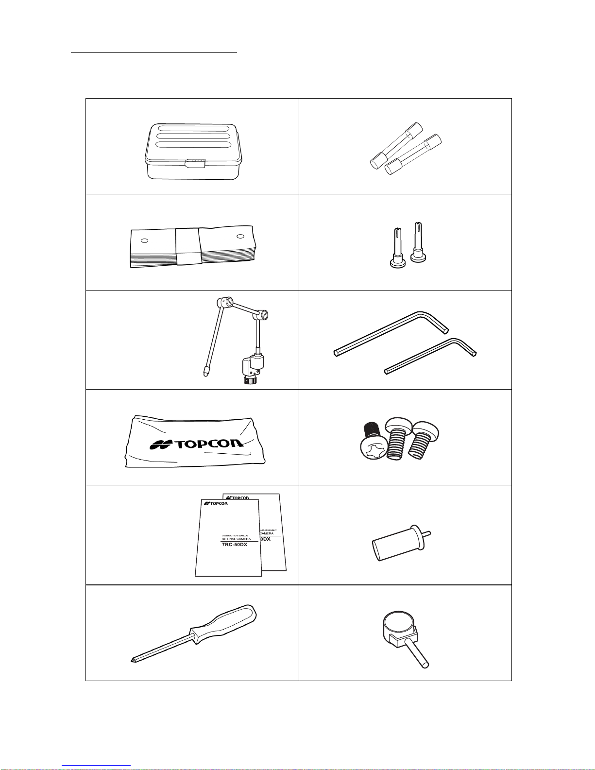
STANDARD ACCESSORIES
Upon unpacking, make sure that all the following standard accessories are included. Numbers
in ( ) are the quantities.
Spare parts case (1) Fuse (2)
Chinrest tissue paper (1) Chinrest tissue pin (2)
External fixation target (1) Allen wrench (2)
Large: (2.5)
Small (1.5)
Dust cover (1) Screw (for main unit connecting cord) (3)
Instruction manual (1)
Unpacking and assembly
manual (1)
Phillips screwdriver (1) Inclination brake lever (1)
Internal fixation target mount (1)
(Only in relevant products)
19
NOMENCLATURE
Page 22
SETUP
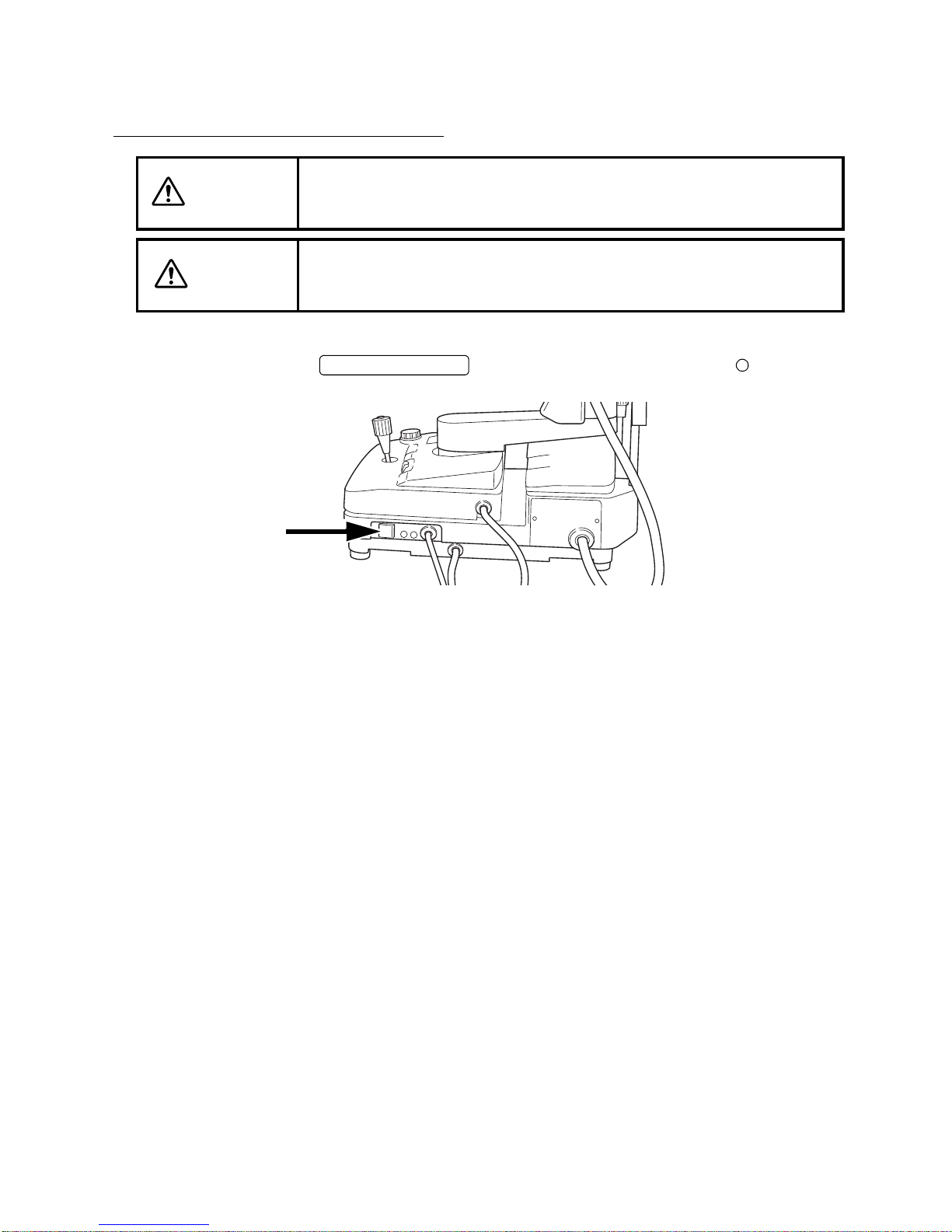
CONNECTING THE POWER CORD
To avoid fire and electri c shock in case of leakage, be sure to use a
WARNING
grounded receptacle. Do not connect to receptacles that are not
grounded.
CAUTION
1 Make sure that the on the instrument is in the "OFF" ( ) position.
To avoid electric shock, do not handle the plugs with wet fingers.
POWER SWITCH
2 Connect the power cord into a grounded outlet.
20
SETUP
Page 23
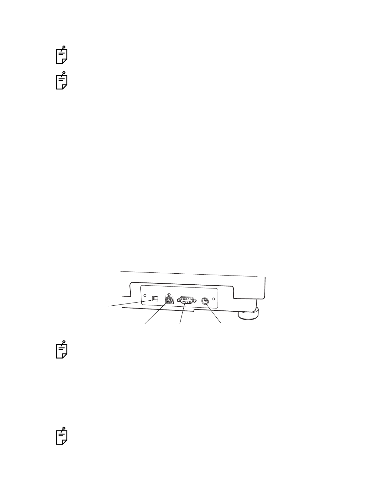
CONNECTING THE EXTERNAL DEVICE
Consult your dealer for connection with external devices.
Use the external device complying with IEC 60950.
Connecting to IMAGEnet
This instrument can be connected to IMAGEnet (optional accessory) by two methods.
Connecting method 1: when using the USB term ina l
1 Connect one end o f the USB cable (optional accessory) to the USB te rminal. Connect
another end of the USB cable to IMAGEnet. Send the data (right/left eye detection indication, angle of coverage indication, etc.) of the instrument from the USB terminal and
receive the data (timer, flash level, etc.) of IMAGEnet.
2 Connect one end of the co nnecting cord (op tional accessory) to the CONTROL termi nal.
Connect another end to IMAGEnet. Performs synchronization.
Connecting method 2: when using the DATA terminal
1 Connect one end of the conne cting cord (optiona l acces sory) to the DATA terminal . Con-
nect another end of the connecting cord to IMAGEnet. Send the data (right/left eye detection indication, angle of coverage indication, etc.) of the instrument from the DATA
terminal.
2 Connect one end of the co nnecting cord (op tional accessory) to the CONTROL termi nal.
Connect another end to IMAGEnet. Performs synchronization.
DATA
CONTROL
USB terminal
DATA terminal CONTROL terminal TIMER terminal
In the U.S. and Canada, use PC which complies with UL60950 or IEC60950.
Connecting to the video timer
TIMER
1 Connect the timer cable (optional accessory) to the TIMER terminal.
2 Connect the timer cable (optional accessory) to the input terminal of the video timer
(optional a ccessory).
3 Connect the video signal cable to the input terminal of the external monitor.
Consult your dealer for the details.
In the U.S. and Canada , use video timer or monitor which co mplies with UL60950 or
IEC60950.
21
SETUP
Page 24

RESET FROM POWER SAVE STATE
This instrument has a power saving feature to save energy.
After 30 minutes of non-use, the instrument switches to power save mode.
In ICG fluorescein photo graphy (only in Type IA), after 60 minutes of non-us e, the instrument
switches to power save mode.
In the power saving state, "SLEEP" is indicated on the control panel.
SLEEP
Control panel
1 Press the of the on the base unit.
After a few seconds, operation is possible.
PHOTOGRAPHY SWITCH
JOYSTICK
22
SETUP
Page 25

SETTING ON THE SET MENU DISPLAY
Setting for the followi ng items can be do ne on the "SET MENU" di splay on the contro l panel:
"FLASH LEVEL" (flash level standard setting), "FIX COLOR" (external fixation color selection),
"FLICK" (external fixation blinking selection) and "FILTER IN/OUT" (filter link operation
method).
1 Press the MENU switch on the setting operation display on the control panel.
2 The "SET MENU" display appears.
FLASH LEVEL (Flash level standard setting)
FIX COLOR (External fixation color selection)
FLICK (External fixation blinking selection)
FILTER IN/OUT (Filter link operation method)
I/F (Interface selection)
EXIT switch
3 Press the switch, and the setting operation display appears again.
EXIT
23
SETUP
Page 26

FLASH LEVEL (Flash level standard setting)
You can set the flash level standard value for each photography mode.
The following table shows the data of the factory default.
1 Press the on the "SET MENU" display.
The "FLASH LEVEL" setting display appears.
FLASH LEVEL
2 Touch the value indication window to be changed in each
photography mode. Black numbers will appear against a
white background.
3 Change the numeral wit h th e and switches. Use the
switch to return to the initial value.
4 Press the switch, to store the data. The "SET
MENU" display will appear again.
If you press the switch, the data will not be
stored. The data is reset as before and the "SET MENU"
display will appear again.
MEMORIZE
RETURN
Type IA
Initial values
UPPER LOWER UPPER LOWER
COLOR 18 50 COLOR 18 50
GREEN 25 50 GREEN 25 50
FA 36 200 FA 36 200
BLUE 18 150 BLUE 18 150
FREE1 9.0 9.0 AF 36 200
FREE2 9.0 9.0 IA NF ---
Type IA
24
SETUP
Page 27

FIX COLOR (External fixation color selection)
You can select "AUTO" (automatic) or "GREEN" or "RED" for the external fixation lamp.
"AUTO" is the factory default.
1 Press the on the "SET MENU" display.
The "FIX COLOR A UTO/GREEN/ R ED" s el ec ti on displ ay w il l
appear.
2 Press and select , or .
When you select "AUTO", color is automatically selected
according to the photography mode.
3 Press the switch, to store the data. The "SET
MENU" display will appear again.
If you press the switch, the data will not be
stored. The data is reset as before and the "SET MENU"
display will appear again.
Press the swit ch, and "GREE N" is set in ICG fluorescein photography and "RED" is set in other photography modes.
FLICK (External fixation blinking selection)
You can set the external fixation lamp to "blinking" (ON) or "lighting" (OFF).
"OFF" is the factory default.
FIX COLOR
AUTO GREEN RED
MEMORIZE
RETURN
AUTO
1 Press the switch on the "SET MENU" display.
The "FLICK ON/OFF" selection display will appear.
2 Press and select or .
3 Press the switch, to store the data. The "SET
MENU" display will appear again.
If you press the switch, the data will not be
stored. The data is reset as before and the "SET MENU"
display will appear again.
FLICK
ON OFF
MEMORIZE
RETURN
25
SETUP
Page 28

FILT ER IN/OUT
Decide the Ba (barrier) filter or Ex (exciter) filter link operation method.
"OUT" is the factory default.
1 Press the switch on the "SET MENU" display.
The "FILTER IN/OUT" selection display will appear.
2 Press and select or . (Refer to the table below.)
3 Press the switch, to store the data. The "SET
MENU" display will appear again.
If you press the switch, the data will not be
stored. The data is reset as before and the "SET MENU"
display will appear again.
When you set the link operation of the Ba (barrier) filter and the ,
the relevant un its will operate as shown in the fol lowing table because of the rela tion
between the setting for "FILTER IN/OUT" on the "SET MENU " display and the
switch on the control panel.
FILTER IN/OUT
IN OUT
MEMORIZE
RETURN
PHOTOGRAPHY SWITCH
FILTER
SET MENU
FILTER
IN/OUT
The switch is displayed when the filter for fluorescein photography is set.
IN
OUT
FILTER
FILTER switch
ON
(The background of switch is black.)
Press the ,
and the Ba (barrier) filter is inserted
and it stays there.
Each time you press the
PHOTOGRAPHY SWITCH
rier) filter is inserted and removed.
PHOTOGRAPHY SWITCH
, the Ba (bar-
OFF
(The background of switch is white.)
The Ba (barrier) filter is not linked
with the .
If you press the Ba (barrier) filter
switch, photograph y with blue filter is
possible.
PHOTOGRAPHY SWITCH
26
SETUP
Page 29

I/F
Set the interface to "USB" or "NORMAL".
"NORMAL" is the factory default.
1 Press the switch on the "SET MENU" display. The
"USB/NORMAL" selection display will appear.
I/F
2 Press and select "USB" or "NORMAL".
3 Press the switch, to store the data. The "SET
MENU" display will appear again.
If you press the switch, the data will not be
stored. The data is reset as before and the "SET MENU"
display will appear again.
Refer to "CONNECTING THE EXTERNAL DEVICE" on
page 21. Select " USB" for the connec ting method 1, and
"NORMAL" for the connecting method 2.
MEMORIZE
RETURN
27
SETUP
Page 30

BASIC OPERATIONS
PREPARATION FOR PHOTOGRAPHY
1 Check the connection of the power cord . Refer to "CONNECTING THE POWER CORD"
on page 20 for the connection procedure.
2 Set each POWER SWIT CH on the in strument and the exte rnal reco rd device t o the "ON"
(I) position.
3 Make sure that the instrument is position ed horiz on tally.
If the instrument is not set horizontally, incline it up and down until the "Horizontal" index
window is red. Swing the instrument right and left and stop it where the direction of the 1st
arm is fit to that of the 2nd arm. Refer to "PHOTOGRAPHY BY INCLINATION AND
SWINGING" on page 42.
"Horizontal" index
window
Inclination brake knob
Swing arm
locking lever
Inclination handle
To fix the instrument, tighten the inclination brake knob and swing arm locking lever.
Fit the direction of
1st arm to that of
2nd arm.
4 Adjust the dioptric power of the optical finder.
How to adjust the dioptric power:
Place a white paper i n tigh t contact with the objec tive lens ba rrel. (Be careful not to touch
the lens.)
Turn the eyepiece lens counterc lockwise to put it o ut fully. Then, gradually turn the eyepiece lens clockwise and, when the reticles (double cross-hairs) are seen clearly, stop
turning.
Dioptric power of optical finder
Out of focus In focus
Inaccurate dioptric power adjustment results in unfocused photos.
Refer to "NAMES IN OPTICAL FINDER" on page 18.
28
BASIC OPERATIONS
Page 31

5 How to move the instrument by the control lever.
• To move the base unit sligh tly back an d forth or right and left, tilt the control lever in the
proper direction.
Operation of control lever
(back and forth/right and left)
Guiding the ba se c over wi th on e hand , push th e con trol leve r with t he oth er ha nd in the
desired direction. You will move the instrument easily.
• To move the instrument body up and down, turn the control lever clockwise to move it up
and counterclockwise to move it down.
Operation of control lever
(up and down)
29
BASIC OPERATIONS
Page 32

PREPARATION OF THE PATIENT
CAUTION
CAUTION
NOTE
To avoid injury while moving the chinrest up and down, instruct the
patient to keep hands away from moving parts.
Be careful not to l et the patient hold the colu mn. His/her finger m ay
be pinched between the column and 1st/2nd arm causing injury.
Ask the patient to remove any glasses or contact lenses.
1 Drop the mydriatic age nt in the patient's e yes to achiev e full dila tion. Make su re that the
patient's pupils are fully dilated before beginning photography.
If dilation is inadequate:
When the pupils are only dilated from 4.5mm to 5.5mm, press the .
(If the pupils are dilate d to 4.5mm or less, photography is not pos sible.) Also, photograph at an angle of coverage of 35° or 20°. When photo graphed at the 50° angle, it
may not be possible to eliminate flare completely.
* Do not use the in other cases except when dilation of the pupil is
inadequate.
SMALL PUPIL SWITCH
SMALL PUPIL SWITCH
4.5~5.5mm 5.5mm or more
2 Lead the patient to the photography room.
3 Pull the instrument properly to the operator side.
4 Let the patient sit down in front of the instrument.
5 Adjust the height of the table o r the chair so that the patient can relax with his/her chin
placed centrally on the chinrest. Then, let the patient rest his/her chin on the chinrest.
30
BASIC OPERATIONS
Page 33

6 Adjust the chinrest hei ght by tur ni ng the chinr es t adj ustin g kn ob s o that the outsid e co rn er
of the patient's eye is leve l with th e Canthus marker on the chin re st col um n. The n, l et the
patient rest his/her forehead on the forehead rest. Use the headband if necessary.
(The headband is installed only in the relevant products.)
Canthus marker
7 Guide the patient's eye so that the target part of the fundus can be photographed.
Guide the patient's eye appropriately by moving the external fixation target.
If it is difficult to fix the patient's eye on the target due to myopia or others, turn ON the
"FLICK" (External fixation blinking selection) on the "SET MENU" display to blink the external fixation target for fixing the patient's eye more easily.
Refer to "FLICK (External fixation blinking selection)" on page 25.
31
BASIC OPERATIONS
Page 34

COLOR PHOTOGRAPHY
CAUTION
CAUTION
CAUTION
CAUTION
CAUTION
CAUTION
To avoid di scomfort or damage to the patient's eye, do not brighten
the illumination lamp more than necessary.
To avoid discomfort or damage to the patient's eye, do not make a
flash intensity level higher than necessary.
To avoid injury wh ile moving the base, do not plac e your fingers into
the gap between the instrument base and the power supp ly unit.
To avoid inju ry while inclining the in strument body, do not place your
fingers into the gap between the instrument body and the 1st arm.
To avoid injury wh ile moving the instrument body, do not place your
fingers into the gap between the 1st/2nd arm and the chinrest column.
* Please give proper instructions to the patient.
Pay attention to the clearance between the objective lens and the
patient.
When the main body is m oved, the objective le ns may b ump agains t
the patient's eye or nose inflicting a minor injury.
To ensure corre ct imaging, adjust the height of the automatic instru-
NOTE
1 Set the to "N".
FILTER SWITCHING KNOB
2 Select the camera with the of the base unit.
• In the case of the 35mm camera, check the film.
• In the case of the video camera, check the recording condition of the camera.
ment table so that the patient ca n relax with his/her chin placed ce ntrally on the chinrest.
UPPER/LOWER SELECTOR SWITCH
LOCK LOCK
FREE FREE
32
BASIC OPERATIONS
Page 35

3 The flash level is automatically changed according to photography modes.
Set the flash level.
Set flash level with the and the .
FLASH SELECTOR SWITCH FLASH CORRECTION SWITCH
Flash correction switch
Flash selector switch
4 Tell the patient to watch the external fixation target or the inter-
nal fixation target (only in Type IA).
5 Align the illumination light with the patient's pupil.
Set the illumination level with the .
You can c heck the s et leve l by lo oking at the illum inatio n leve l
display on the control panel.
ILLUMINATION LEVEL KNOB
How to properly align the illumination light:
First look at the patie nt's pupil from th e side of the i nstrument. To make the illumination light
coaxial to the patient 's pupi l, move r oughly the ma in body to a po sitio n about 4 0mm in front o f
the patient's eye with the joystick positioned straight, and then, adjust the joystick up and down/
right and left. Then, fin ely a dju st the joystick to image the r in g sli t o n th e c or nea c oaxia ll y with
the patient's pupil.
• Ring slit images on cornea
• Images observed by viewfinder
• Images acquired by camera
33
BASIC OPERATIONS
Page 36

6 Push the base unit toward the patient side slowly, and the retinal image is seen in the opti-
cal finder.
7 Watching the observed image in the optical finder, adjust its brightness with the
ILLUMINATION LEVEL KNOB
.
8 Finely adjust the main body forward and backward to illuminate the retina evenly.
• When the alignment bright spots are used:
Press the on the control panel.
Move roughly the main body in to a posit ion abou t 40 mm in f ront of t he patient's eye with the
joystick positioned st raig ht. T hen ad just t he j oysti ck u p and d own / righ t an d left until the illumination light becomes coaxial wi th the patient 's pupil. The alignment brig ht spots will app ear
on the right and left sides in th e optical fi nder. Make these spots as small as possible.
If the patient moves the eyes or when photographing the periphery by tilting or swinging,
sometimes the alignment bright spots on the right and left disappear.
ALIGNMENT SWITCH
• Adjust alignment so that flares cannot be seen.
• The instrument can be used as mentioned above for the front of 50°.
• When the angle of c ov erage is ch ange d or whe n pho togr ap hi ng the perip her y, it is not
possible to use the alignment bright spots.
9 Focus the retina.
• How to focus the retinal image with the split lines* (Only in "With split" type)
Set the internal fixation target (only in Type IA) to the "OFF" posi tion, and turn on the
SPLIT SWITCH
Turn the focusing knob to align the right and left split lines.
* The split lines cannot be used if the is set
other than "0".
.
DIOPTER COMPENSATION LENS SELECTOR
Ex
SPLIT
TIME
Ba
34
BASIC OPERATIONS
Page 37

If you cannot align the split lines into one line by operating the focusing knob, change the
diopter compensation lens by the diopter compensation lens selector.
If the split lines are not easily visible, lower the illumination level.
If one of the split lines cannot be seen, check if dilation is sufficient or if the eye is
obstructed by eyelashes or the eyelid, interrupting the light.
When the split lines are not necessary, they can be deleted from the optical finder.
Press the , and the split lines disappear from the optical finder.
Press the again, and the split lines are displayed in the optical finder.
• How to sharply focus the retinal image:
While looking in to th e op tic al fin der, turn the focusi ng k no b s o th at th e r etinal im age and
the reticles are observed sharply and distinctly in the field at the same time.
SPLIT SWITCH
SPLIT SWITCH
How to adjust focus easily
Press the switch of "APERTURE" (p hotography aperture). (Th is can be used in
color photography and ICG fluorescein photography (only in Type IA).)
How to photograph retinal peripheries
Have the patient watch the external fixation target correctly with the eye that is not being
photographed. Then, photograph the peripheries.
It will be pos sible to photo graph the perip heries of the retina, by tilt ing and/or sw inging
the main body. (Refer to P. 42.)
When photograph ing the r etinal peripheri es, the s plit lines are de viated. Take a pictu re
so that retina may be in focus.
SMALL
10 Set the angle of coverage.
Move the to set the angle of coverage to 50°, 35° or 20°.
To check the angle in use, see the picture angle display on the control panel screen.
Pay attention to the relationship between fla re and focus due to difference in a ngle of
coverage. If flare is elimi nated at the 50° angle of coverage, no fla re occurs at 35° or
20°. Furthermore, refocusing is unnecessary at 50° if the retinal image has already
been properly focused at 35° or 20°.
ANGLE CHANGING LEVER
35
BASIC OPERATIONS
Page 38

11 Make sure that the split line is aligned with the alignment bright spot. Press the
PHOTOGRAPHY SWITCH
If the light intensity of the photography image is not correct, adjust it with the
FLASH CORRECTION SWITCH
How to change the dioptric power compensation
To adjust the dioptric power, turn the according to the
patient's eye condition.
Diopter compensation lens selector
when the patient's eye is fully open. Instruct him/her not to blink.
Photography switch
and repeat the alignment and photography procedure.
DIOPTER COMPENSATION LENS SELECTOR
-
50DX
TRC
Compensation range 0 : -10D ~ +6D
- : -23D ~ -9D
+: +5D ~+23D
A : +22D ~ +41D
When the diopter comp ens ati on len s i s se t to any ot her v alues ex c ept "0", the split lines
are OFF. (Only in "With split" type)
How to change the dioptric power compensation
(This correction unit is installed in one type and not installed in another type.)
According to the astigmatism degree of the
patient's eye, pull out th e astigmatism correc tion
knob and turn the dial to adjust the astigmatism.
The astigmatism c orrection is cla ssified into two st eps, "3D" and "6D". Pu sh the astigmatism correction kn ob to the inne rmost, and the instrument doe s not correc t the astigmatism. Pull out the astigmatism correction knob and set it at "3". The instrument
performs the 3D astigma tism correction. Set it at "6", and the instrument performs the
6D astigmatism correction.
6
3
36
BASIC OPERATIONS
Page 39

F AG PHOTOGRAPHY
WARNING
To avoid fire an d electric shock, do not put c ups or other containers
with liquids near the instrument.
To ensure corre ct imaging, adjust the height of the automatic instru-
NOTE
ment table so that the patient ca n relax with his/her chin placed ce ntrally on the chinrest.
The basic operatio n is the same as "COLOR PHOTOGRAPHY". The only di fference is the
insertion of the fluorescein filters and intravenous injection of fluorescein to the patient.
Preparation
1 Set the to "N".
2 Select the camera with the
FILTER SWITCHING KNOB
UPPER/LOWER SELECTOR SWITCH
of the base unit.
• In the case of the 35mm camera, check the film.
• In the case of the digi tal camera, ch eck the recording condition of the camera.
CK
CK
EE
3 Press the .
Ex SWITCH
When the barrier filter sh ould be operated in the
link condition with the ,
press the on the control panel.
FILTER SWITCH
The barrier filter will be inserted in a link operation with the .
PHOTOGRAPHY SWITCH
The link operation is classified into two types.
You can select one type on the "SET MENU" display on the control panel. (1) is the factory default. Re fer to "F ILTER IN/OUT" on page 26 for the details o f the s etting ch ange
method.
(1) Press the while "IN" is selected for "FILTER IN/OUT" on the
"SET MENU" display.
The barrier filter is inserted when pressing the shutter first and it stays.
(2) Press the while "OUT" is selected for "FILTER I N/OUT" on the
FILTER SWITCH
"SET MENU" display.
The barrier filter is inserted and removed each time you press the shutter.
PHOTOGRAPHY SWITCH
FILTER SWITCH
SPLIT
Ex
Ba
TIME
37
BASIC OPERATIONS
Page 40

4 Make the same a djustments, as 3~10 fo r "COLO R PHOTOGRAPHY ", and f ocus th e reti-
nal image properly.
5 Prepare for the intravenous injection of fluorescein.
How to take distinct fluorescein photographs:
If too much time is taken in giving the intrave nous injection, the fl uorescein will be diffused in the blood vessels and diagnostic quality photographs will not be possible.
6 Press the at the same time as an intrave-
nous injection of fluorescein is given to the patient.
• When the time r starts, it will beep every seco nd up to 20
seconds.
• Also, the will blink simultaneously every
second until the timer goes OFF.
7 Press the .
When the is ON (white letters on b lack ba ckgrou nd), th e bar rier filte r is
inserted into the photography unit in a link operation with the .
8 Press the .
TIME SWITCH
TIME SWITCH
Ba (BARRIER) SWITCH
FILTER SWITCH
PHOTOGRAPHY SWITCH
Photography switch
Ex
SPLIT
Ex
SPLIT
PHOTOGRAPHY SWITCH
Ba
Ba
TIME
TIME
When you keep pressing the , it is possible t o take one (1) pic ture per second.
9 When you have finished photographing, press the to stop the timer.
38
BASIC OPERATIONS
PHOTOGRAPHY SWITCH
TIME SWITCH
Page 41

ICG FLUORESCEIN PHOTOGRAPHY (ONLY IN TYPE IA)
WARNING
NOTE
The basic operation is the same as "FAG PHOTOGRAPHY". The difference is tha t observation of the retina is done with the monitor.
1 Set the to "IA".
The ICG observation infrared camera is automatically selected.
FILTER SWITCHING KNOB
To avoid fire an d electric shock, do not put c ups or other containers
with liquids near the instrument.
To ensure corre ct imaging, adjust the height of the automatic instrument table so that the patient ca n relax with his/her chin placed ce ntrally on the chinrest.
2 Make the same adjustments, as 3~10 for "COLOR PHOTOGRAPHY", and focus the reti-
nal image properly.
Select "AUTO" or " GREEN" with the (External fixatio n color selection) on
the "SET MENU " display of the co ntrol panel to set the external fixation target color to
"green". Near in frared light is used as the illumi nation light so urce. So, it is easy to fix
the eye on the target by selecting a green fixation target.
FIX COLOR
The split lines and alignment bright spot are turned off.
3 Prepare for the intravenous injection of ICG fluorescein.
4 Press the at the same time as an intrave-
nous injection of fluorescein is given to the patient.
• The timer starts.
5 Press the .
When the fluorescein retinal image is fully bright:
• Press the switch of "APERTURE" (photography
aperture), and you can adjust focus easily.
6 Press the .
7 When you have finished photographing, press the to stop the timer.
TIME SWITCH
Ba (BARRIER) SWITCH
SMALL
PHOTOGRAPHY SWITCH
TIME SWITCH
SPLIT
SPLIT
Ex
Ex
Ba
Ba
TIME
TIME
39
BASIC OPERATIONS
Page 42

RED FREE PHOTOGRAPHY WITH GREEN FILTER
(ONLY IN RELEVANT PRODUCTS)
WARNING
NOTE
1 Set the to "G".
FILTER SWITCHING KNOB
To avoid fire an d electric shock, do not put c ups or other containers
with liquids near the instrument.
To ensure corre ct imaging, adjust the height of the automatic instrument table so that the patient ca n relax with his/her chin placed ce ntrally on the chinrest.
2 Take a picture according to the same procedure as "COLOR PHOTOGRAPHY".
AUTO FLUO (AUTO FLUORESCENCE) PHOTOGRAPHY
(ONLY IN RELEVANT PRODUCTS)
WARNING
NOTE
To avoid fire an d electric shock, do not put c ups or other containers
with liquids near the instrument.
To ensure corre ct imaging, adjust the height of the automatic instrument table so that the patient ca n relax with his/her chin placed ce ntrally on the chinrest.
In the type w ithout the AU TO FLUO filter, this filter can be installed as an option al accessor y.
The intravenous injection of fluorescein is not done.
1 Set the to "AF".
FILTER SWITCHING KNOB
2 Take a picture ac cording to the same procedure as 2~9 for "FLUORESCEIN PHOTOG-
RAPHY".
3 Press the .
When the is "ON" (white letters on black background), the barrier filter is
inserted into the photography unit by a link operation with the .
Ba (BARRIER) SWITCH
FILTER SWITCH
PHOTOGRAPHY SWITCH
40
BASIC OPERATIONS
Page 43

4 Press the .
PHOTOGRAPHY SWITCH
Photography switch
When you keep pressing the , it is possible t o take one (1) pic ture per second.
PHOTOGRAPHY SWITCH
41
BASIC OPERATIONS
Page 44

OBJECTIVE OPERATIONS
PHOTOGRAPHY BY INCLINATION AND SWINGING
To prevent the instrument from malfunctioning, do not perform inclina-
NOTE
tion and base swinging ( right and left) while h olding the camera connected to UPPER or LOWER mount.
1 When performing incli nation, loo sen the gradually until you can
move the .
INCLINATION HANDLE
2 Change the inclined angle of the instrument with the .
The allowable inclined angle is u p to 15° in the upp er directi on and up to 1 0° in the lo wer
direction.
Inclination brake knob
Inclination handle
3 When performing swinging, loosen the on the .
INCLINATION BRAKE KN OB
INCLINATION HANDLE
SWING ARM LOCKING LEVER 2ND ARM
4 Push the side of the instrumen t lightly or pull the focus in g kno b to ch ange the swi ng angle
of the instrument.
The allowable swing angle is up to 30° in the right and left direction.
Swing arm locking lever
5 Perform inclination and swinging until you get a desired position and then take a picture.
6 Perform alignment and photography for the eye according to the same procedure as
"COLOR PHOTOGRAPHY".
When performing inclination and swinging, the split lines and alignment bright spot
should be regarded as standard.
42
OBJECTIVE OPERATIONS
Page 45

BLUE FILTER PHOTOGRAPHY
To ensure corre ct imaging, adjust the height of the automatic instru-
NOTE
The basic operation i s the same as "COL OR PHOTOGRAPHY". It is p ossible to photograph
with the EXCITER filer as the blue filter by setting the to "OFF".
ment table so that the patient ca n relax with his/her chin placed ce ntrally on the chinrest.
FILTER SWITCH
1 Set the to "N".
2 Press the to "OFF" on the control panel. (Black letters will appear on
white background.)
The barrier filter is not linked with the shutter.
3 Press the .
FILTER SWITCHING KNOB
FILTER SWITCH
EXCITER SWITCH
4 Perform alignment and photography for the eye according to the same procedure as
"COLOR PHOTOGRAPHY".
Press the , and the barrier filter is inserted. Press it again, and the
barrier filter retreats.
PHOTOGRAPHY WITH ALTERNATIVE FILTER (EXCLUDING TYPE IA)
The filter frames F1/F2, which can be installed/removed, are available. Set an alternative filter
and take a picture. The bas ic operation is the s ame as "RED FREE PHO TOGRAPHY WITH
GREEN FILTER" on page 40.
Ba (BARRIER) SWITCH
Use a filter which cuts off the ultraviolet rays and infrared rays.
Refer to "How to install the AUTO FLUO Ex filter" on page 63 for changing the filter.
43
OBJECTIVE OPERATIONS
Page 46

STEREO PHOTOGRAPHY
Allow the illumina tion light to come into the patient's pupil so that uniform b rightness can be
kept on the eye. Then, take a picture using the . The basic operation is the
same as "COLOR PHOTOGRAPHY".
STEREO LEVER
1 Align the patient's pupil and the instrument in proper positions.
Unless the instrumen t's optical axis aligns with the pupi l's optica l axis in the up-an d-down
and right-and-left directions, flares will occur on one side. Be careful.
Refer to "How to properly align the illumination light" on page 31.
As flares easily appea r at an a ngle of c overag e of 50°, i t is s uggest ed that s tereo photo graphy is taken at an angle of coverage of 35° or 20°.
2 Affix the .
STEREO LEVER
STEREO STEREO
FREE FREE
3 Move the instrument gently until it stops in the right and left direction and press the
PHOTOGRAPHY SWITCH
Unless you mov e the ins trument unti l it stops, the effect of the stereo separ ation will be
reduced.
(SHUTTER) in each position.
44
OBJECTIVE OPERATIONS
Page 47

INTERNAL FIXATION TARGET MOUNT (ONLY IN TYPE IA)
Internal fixation target mount (in "With split" type of Type IA)
1 Look into the optical finder and focus the retinal image.
2 Turn off the .
* If the is turned on, the knob will be
locked.
SPLIT SWITCH
SPLIT SWITCH
SPLIT
EX
Ba
TIME
3 Move the knob to guide the patient's eye.
The knob can be pushed and pulled and moved ba ck and forth. The fixation point will
move left/right and ba ck/forth by operati ng the kn ob. Focus ing is not n ecessar y. Move it
slowly to guide the patient's eye.
4 Perform alignment and photography for the eye according to the same procedure as
"COLOR PHOTOGRAPHY".
* The fixation point will also be photographed with the retinal image.
* When using the SPLIT lines, br ing the knob to the "OF F" position and then tu rn on the
SPLIT SWITCH SPLIT SWITCH
graphs cannot be taken. Be sure to set the knob to the "OFF" position.
Knob
. If the is ON without setting the knob to "OFF", photo-
Move back and forth.
Internal fixation target mount (in "Without split" type of Type IA)
• Operating procedures
(1) Move the knob and guide the patient's eye with the fixation point, while checking
movement through the finder.
The knob moves in every direction. Up-and-down movement is used for o btaining proper foc us, while ri ght-andleft and back-and-forth movements are used to move the
fixation point in the finder. Movement should be done
slowly, in order not to confuse the patient when guiding
the patient's eye.
• Along with the ret inal image, the fixation point is also
recorded. (Present in the photograph)
Push and pull.
Fixation point
45
OBJECTIVE OPERATIONS
Page 48

BEFORE REQUESTING SERVICE
TROUBLESHOOTING
WARNING
To avoid electric s hoc k, do not attem pt di sa ss em bli ng, rebu il ding and/
or repairs on your own. Ask your dealer for repairs.
Do not remove the external co ve rs from th e mai n un it, c hi nres t uni t or
WARNING
power supply u nit ex cept for the lamp hous e co ve r. You m ay r eceive
an electric shock.
When an error is found, review the Check List below.
If, after following the instr uctions below, you still have pr oblems or if t he problem does not fall
into any of the categories below, contact your dealer or TOPCON (see the back cover).
Check List
Problem Condition Check Page
Periphery of photograp hed
image is dark.
Photographed image is
flared all over. (The whole
image is covered by light.)
Photographed image is
whitened.
Photographed image has
a dim white spot.
Photographic image is
dark all over.
Illumination lamp does not
turn on.
The external fixation target does not light/blink.
• Operation distance (alignment) is incorrect.
• Focusing is incorrect. Adjust focus. 35
• Patient's pupil is not large enough. Darken room and thoroughly dilate
• Operation distance (alignment) is incorrect.
• Focusing is incorrect. Adjust focus. 35
• Opacity in patient's eye Flare caused by opacity cannot be
• Patient blinked the moment the photograph was taken.
• Objective lens is stained. Clean lens. 60
• Eyelashes were in patient's eye the
moment the photograph was taken.
(Dim light was seen at screen bottom
the moment the alignment was done.)
• Flash level is insufficient. Adjust the flash level with the flash cor-
• Xenon lamp set screw is loose. Fix xenon lamp securely. 55
• Xenon lamp has served its life. Change xenon lamp. 55
• Power save function is on.
("SLEEP" is indicated on the control
panel.)
• Lamp terminal is loose. Refasten lamp terminal. 54
• Fuse is burnt. Change fuse. 57
• Lamp is burnt. Change lamp. 54
• Lamp house cover is not set. Set Lamp house cover properly. 55
• Fuse is burnt. Change fuse. 57
Adjust operation distance (alignment). 29
patient's pupil.
Adjust operation distance (alignment). 29
removed.
Take another picture. ---
Let patient open eye wider and take the
picture again. If not wide enough, open
the eyelid (i.e., Take picture holding eyelid open).
rection switch or flash selector switch.
Press photography switch and cancel
power save function.
30
---
29
15
22
46
BEFORE REQUESTING SERVICE
Page 49

Problem Condition Check Page
Split lines cannot be seen. • SPLIT switch is set to OFF. Turn SPLIT line ON with Split switch. 15
Xenon lamp does not turn
on.
Cannot get patient's pupil
at center.
Nothing is recorded in
external recording device.
The 35mm UPPER camera does not work.
Black dots are seen in the
photographed image.
Flare cannot be eliminated
at angle of coverage 50°.
Correct focus is not possible.
• Diopter compensation lens selector is
not set to "0".
• Patient's pupil is not large enough. Darken room and thoroughly dilate
• The internal fixation target is not set to
"OFF".
• Power save function is on.
("SLEEP" is indicated on the control
panel.)
• Xenon lamp has served its life. Change xenon lamp. 55
• Fuse is burnt. Change fuse. 57
• Xenon lamp set screw is loose. Refasten lamp terminal. 54
• The NF switch on the base unit is
pressed.
• Patient's face position is incorrect. (The
chin and forehead are not correctly on
the rests, or the patient faces sideways.)
• Patient's face height is incorrect. Adjust face height with Chinrest adjust-
• Anomaly in external recording device. Check power supply, settings, etc. ---
• Cable connections are incorrect. Check and correct cable connections. 21
• Power save function is on ("SLEEP" is
indicated on the control panel.)
• The battery for camera is dead. Replace the battery. ---
• Fuse is burnt. Change fuse. 57
• UPPER/LOWER se lector swi tch on the
base unit is not set to "UPPER".
• The 1× relay lens is not attached firmly. Attach the 1× relay lens firmly. 68
• The camera is not fixed properly to the
1× relay lens.
• The shading compensation cover is
stained.
• Angle changing lever is not set at the
"click" position.
• The microcoria mode is set because
SMALL PUPIL switch is pressed.
• The patient's eye and instrument are
not positioned correctly.
• The patient's eye is not fully dilated. Dilate the patient's eye fully. 30
• The optical finder dioptric power is not
adjusted.
• Diopter compensation lens selector is
not adjusted properly for the dioptric
power of the patient's eye.
• The patient's eye is clouded due to cataract.
• The patient's eye is filled with tears. ---
• The patient's eye and instrument are
not positioned correctly.
Return Diopter compensation lens selector to "0".
patient's pupil.
Set the internal fixation target to "OFF". 45
Press photography switch and cancel
power save function.
Press Flash selector switch to set the
flash level.
Have patient keep his/her position correctly.
ing knob.
Press the photography switch to cancel
power save function.
Press UPPER/LOWER selector switch to
set it to "UPPER" .
Fix the camera on the 1× relay lens properly.
Perform cleaning with a blower, etc. ---
Turn Angle changing lever to the "click"
position.
Press SMALL PUPIL switch to cancel
the microcoria mode.
Set the patient's eye and instrument correctly.
Adjust the optical finder dioptric power. 28
Adjust Diopter compensation lens selector to the dioptric power of the patient's
eye properly.
Set the patient's eye and instrument correctly.
12
30
22
33
30
30
22
15
68
12
16
29
12
29
---
47
BEFORE REQUESTING SERVICE
Page 50

Problem Condition Check Page
Operator cannot see the
patient's eye.
Internal fixation target
mount does not work.
Photograph of the retinal
peripheries is dark.
• Illumination light is not ON. Adjust the illumination level. 33
• The objective lens cap is set. Remove the objective lens cap. ---
• BARRIER filter and EXCITER filter are
set to "IN".
• Angle changing lever stops in the middle of the "click" process.
• Diopter compensation lens selector
stops in the middle of the "click" process.
• SPLIT switch is not set to "OFF". Set SPLIT switch to "OFF". 15
• The distance between the patient's eye
and the instrument is longer than the
proper working distance.
Set BARRIER filter and EXCITER filter to
"OFF".
Turn Angle changing lever to the "click"
position.
Turn Diopter compensation lens selector
to the "click" position.
Set the patient's eye closer to the instrument and then take a picture.
15
12
12
29
Photograph of retinal center is dark.
Photograph is influenced
by overall flare.
V ague white dots are seen
through the finder and
also appear on the photograph.
• The pupil of the patient's eye is not fully
dilated.
• The distance between the patient's eye
and instrument is shorter than the
proper working distance.
• SMALL PUPIL switch is pressed in
angle of coverage 50°.
• Flash level is higher than necessary. Set the flash level to a low value. 33
• Tears or others adhere to the objec tive
lens.
Dilate the patient's eye fully. 30
Set the patient's eye far away from the
instrument and then take a picture.
Press SMALL PUPIL switch to cancel
the microcoria mode.
Clean the objective lens. 60
29
16
48
BEFORE REQUESTING SERVICE
Page 51

ERROR CODE LIST
When "Err " ( mea ns an err or num ber ) is dis pl ayed i n the blinking status on th e co ntrol panel screen with a beep sound due to an operat ion error or a malfunct ion of the instrument, correct the error according to the table below.
Display Cause How to correct
Err0 The lamp house cover is opened. Close the lamp house cover firmly.
Err1 Overcharge or undercharge of charge
voltage.
Err2 USB cable is not connected properly. Check the connection of the USB
Err3 FAG exciter filter does not work properly. Consult your dealer.
Err4 Nothing (Not used) Nothing (NA)
Err5 Photography aperture original point sensor
does not work properly.
Err6 Barrier filter motor sensor does not work
properly.
Err7 Angle sensor does not work properly. Operate the angle changing lever again.
Err8 The mirror and filter of the T V relay lens do
not work properly.
Err9 Desired filter does not work properly. Operate the desired filter again.
Err10 Illumination aperture does not work properly. Consult your dealer.
Err1 1 Internal fixation target does not work
properly.
Consult your dealer.
connector.
Consult your dealer.
Consult your dealer.
Consult your dealer.
Move the internal fixation target to the
"OFF" side.
When any other err or except "Err0", "Err2" , "Err7", "Err9" and "Err11" is displayed, co nsult your
dealer.
49
BEFORE REQUESTING SERVICE
Page 52

50
SPECIFICATIONS AND PERFORMANCE
SPECIFICATIONS AND PERFORMANCE
SPECIFICATIONS
• Resolving power of the fundus camera
(Examined eyes 0D, on 35mm film surface)
• Angle of coverage : 50°/35°/20°
• Photography magnification : When the patient's eye is 0D, 35mm film is used:
50°: 1.84×
35°: 2.45×
20°: 4.28×
• Dioptric power adjustment range of optical finder : -6D ~ +5D
• Focus range to compensate the refraction trouble of the patient's eye :
0 : -10D ~ +6D
- : -23D ~ -9D
+: +5D~+23D
A : +22D ~ +41D
• Operating distance : 39.0mm
• Base movement
Back and forth : 80mm
Right and left : 110mm
Fine movement : 12mm
Up and down : 30mm
• Up-and-down inclined angle : Upper 15°/Lower 10°
* The specifications and design are subject to change without prior notice for improvement.
ELECTRIC RATING
Source voltage : 100-120V/200-240V FREQ. 50-60Hz
Power : 1500VA
unit : lp/mm
angle part radial tangential
50°
center 63 63
middle (r/2) 50 50
periphery (r) 40 40
35°
center 80 80
middle (r/2) 63 63
periphery (r) 50 50
20°
center 100 100
middle (r/2) 80 80
periphery (r) 63 63
Page 53

SYSTEM CLASSIFICATION
• Types of protection against electric shocks:
This instrument is classified as Class I equipment.
Class I equipme nt does not depend only on bas ic insulation for protection ag ainst electric
shocks, but also provide s a means of connec tion to a prote ctive earth sy stem of facili ties so
that metal parts that come into contact do not become conductive while the basic insulation is
in failure.
• Degree of protection against electric shocks: Type B applied part
Type B applied part is the applied part complying with the specified requirements of the Standard IEC 60601-1 to prov ide protection against electric shock , particularly regarding allowable LEAKAGE CURRENT.
• Degree of protection against harmful ingress of water: IPx0
The TRC-50DX has no protection against ingress of water. (The degree of protection against
harmful ingress of water defined in IEC 60529 is IPx0.)
• Classificat ion ac cordin g to the met hod(s) of ste riliza tion o r disin fecti on recom mended by the
manufacturer: not applicable.
The TRC-50DX has no part to be sterilized or to be disinfected.
• Classification according to the degree of safety of application in the presence of a flammable
anesthetic mixtu re wit h air or with ox ygen o r nitrou s oxi de: Equ ipmen t not su itable f or use in
the presence of a flammable anesthetic mixture with air or with oxygen or nitrous oxide.
The TRC-50DX should be used in environments where no flammable anesthetics and/or
flammable gases are present.
• Classification according to the mode of operation: Continuous operation.
Continuous opera tion i s the o peration under normal load f or an unlim ited pe riod, wi thout the
specified limits of temperature being exceeded.
DIMENSIONS AND WEIGHT
Dimensions : 340mm (W) × 505mm (D) × 506~715mm (H)
Weight : 35kg (only the instrument)
PURPOSE OF USE
To observe, take pictures or record pictures of the posterior segment of the eye through the
pupil.
51
SPECIFICATIONS AND PERFORMANCE
Page 54

OPERATION PRINCIPLE
The observation lig ht emitted from the illumination opti cal system ill uminates the patient's eye
(the eye to be photographed), and the image formed by the observation/photography optical
systems is observed. By operating the photography switch on the instrument, the photography
light is emitted from the illu mination optical syste m to illuminate the patient's eye. The image
formed by the o bservation/ph otography o ptical syst ems is ph otographed a nd recorded by the
35mm film camer a (a prod uct in the mar ket) or an elect ronic photo graph y dev ice (a pr oduct in
the market).
The following fi lters, which can be installe d/removed, are built in the illumination optical s ystem: One is the Ex filter and this selects and transmits the light that excites the fluorescent coloring matter in FAG photography. The other is the ICG-Ex filter and thi s selec ts and transm its
the infrared ligh t that excites the fluore scent coloring matter in ICG fluorescein photography.
(The ICG-Ex filter is built in only Type IA.)
The following fil ters a re bu il t i n the ob servation/photograp hy o pti cal systems: On e is th e Ba fi lter and this selects and filtrates the fluores cent wavele ngth in FAG photography. The other is
the ICG-Ba filter and this selects and filtrates the fluorescent wa velength in ICG fluorescein
photography. (The ICG-Ba filter is built in only Type IA.)
The angle of coverag e can be changed by chan ging the lens located in the observation/photography optical systems. The illumination aperture located in the illumination optical system is
changed in the li nk operation with the chan ge of the angle of coverag e. So, the illumination
level is adjusted properly for photography.
The photography ape rture located in the obs ervation/photo graphy optical s ystems is changed
properly for photography according to the photography technique.
52
SPECIFICATIONS AND PERFORMANCE
Page 55

MAINTENANCE
CAUTION
To prevent damag e and injuries, do not install the instrument on an
uneven, unsteady or sloped surface.
DAILY CHECKUPS
• Before using this instrument, always inspect it.
• Each time you use this instrument, clean it according to "CLEANING" on page 60.
• Dust is a formidable foe to the instrument.
• To ensure the production of fine images, care should be taken not to allow fingerprints and/or
dirt on the objective lens.
• When not in use , be sure to cap the objective len s and cover the instrument with the dust
cover.
• Before using the instrument, check if the objective lens is clean. If the objective lens is
stained, clean it foll owing the inst ructi ons for "CLEA NING THE OBJE CTIVE LENS" on page
60.
• When not in use, always turn the OFF.
POWER SWITCH
ORDERING CONSUMABLES
• When ordering consumables and spare parts, contact your dealer or TOPCON (see the back
cover) and tell them the article name, article code and quantity.
Article name Article code Article name Article code
Illumination lamp 40535 40200 Fuse 15A 125V (for 100V/120V) T24000086A
Xenon lamp 40413 16200 8A 250V (for 230V) T24000085A
Chinrest tissue paper 40310 4082
Dust cover 40488 1007
MAINTENANCE BY THE DEALER
Item Inspection interval Details
Cleaning each unit Within 12 months from
the last maintenance
Checking the operation Within 12 months from
the last maintenance
Checking photography Within 12 months from
the last maintenance
• Cleaning the external section
• Cleaning the optical system
• Cleaning the base unit
• Operation of the main body
• Operation of the switches
• Focus, flare, center ghost and dust
• Checking the xenon light intensity
(by the special tool)
53
MAINTENANCE
Page 56

REPLACING THE ILLUMINATION LAMP
CAUTION
CAUTION
NOTE
NOTE
• The service life of the illumination lamp is approx. 2000 hours.
Replace the illumination lamp if it is burned out or becomes whitened.
1 Turn the OFF and unplug the power cord.
POWER SWITCH
To avoid electric shock, be sure to turn the power switch off and
unplug the power cord before replacing the lamp.
To avoid burns, d o not replace the lam p with a new one imm ediately
after it goes off. Allow time for it to cool.
To avoid whitening due to fingerprints, do not touch the lamp with bare
fingers.
Since the lamp is not resistible to shocks, handle it with particular
care. Do not drop.
2 Turn the control lever to raise the instrument body to its limit.
3 Remove the screw. Then, push the bottom of the l amp ho use cov er and pull it for ward to
remove it.
4 Loosen the two fixing screws and pull out the illumination lamp unit straight.
54
MAINTENANCE
Screw
Illumination lamp unit
Illumination lamp unit fixing screw
Page 57

5 Insert the new illuminat ion lamp straig ht and tighten s ecurely the two fix ing screws of the
illumination lamp.
6 Attach the lamp house cover by matching the projection at t he bottom part of the lamp
house cover with the groove of the body cover.
If the lamp house cov er is left unfixed, an error is displayed on the contro l panel and
operations, includi ng phot ogr ap hy, cannot be done.
REPLACING THE XENON LAMP
CAUTION
CAUTION
NOTE
NOTE
• The service life of the xenon lamp is approx. 10000 flashes.
Replace the xenon lamp if it is burned out or becomes whitened.
1 Turn the OFF and unplug the power cord, then wait for more than 5 min-
utes for the natural electrical discharge.
POWER SWITCH
To avoid electric shock, be sure to turn the power switch off and
unplug the power cord before replacing the lamp.
To avoid electric shock, do not replace the xenon lamp with a new one
immediately after it goes off.
To avoid whitening due to fingerprints, do not touch the lamp with bare
fingers.
Since the lamp is not resistible to shocks, handle it with particular
care. Do not drop.
2 Push the bottom of the lamp house cover and pull it forward to remove it.
3 Remove the xenon lamp set screw by turning it counterclockwise with a coin.
Xenon lamp set screw
55
MAINTENANCE
Page 58

4 Slowly pull the xenon lamp straight out.
5 Insert the new xenon lamp straight in the receptacle until it reaches the end.
6 Tighten the xenon lamp set screw fully with a coin clockwise.
7 Attach the lamp house cover by matching the projection at t he bottom part of the lamp
house cover with the groove of the body cover.
If the lamp house cov er is left unfixed, an error is displayed on the contro l panel and
operations, includi ng phot ogr ap hy, cannot be done.
56
MAINTENANCE
Page 59

REPLACING THE FUSE
To avoid electric shock when replacing the fuse, be sure to unplug the
WARNING
instrument before rem oving the fuse cover. Do not use ungrounded
outlets. Do not plug in the instrument without the fuse cover.
WARNING
1 Turn the OFF and unplug the power cord.
POWER SWITCH
To avoid fire in the event of an instrument malfunction, use only the
fuses that are marked with the label at the side of the fuse holder.
2 With a slotted screwdriver, press and turn the fuse holder counterclockwise and remove it.
Fuse holder
3 Replace the fuse with a new fuse of the same capacity.
4 With a slotted screwdriver, lightly press and turn the fuse holder clockwise and fasten it.
If the fuse has blown out, the whole instrument will not operate. Replace the fuse with a
new one.
Changing the fuse
57
MAINTENANCE
Page 60

REFILLING THE CHINREST TISSUE PAPER
• When the chi nrest tis sue paper is used up , pull o ut the ch inrest tissue pins and r efill the tissue paper.
Chinrest tissue pin(s)
THE FAG FLUORESCEIN FILTER
CAUTION
CAUTION
NOTE
NOTE
How to install the Ex (exciter) filter
1 Turn the ON ( ).
2 Set the to "N".
3 Press the .
4 Turn the OFF ( ).
POWER SWITCH
FILTER SWITCHING KNOB
Ex SWITCH
POWER SWITCH
To avoid electric shock, be sure to turn the power switch off and
unplug the power cord before replacing the filter.
To avoid bur ns due to the hot fil ter u ni t, do no t r epl ace the filter with a
new one immediately after the power goes off.
To prevent the glass fr om whitening due to fingerprints, do not tou ch
the filter with bare fingers.
Since the filter is not resistible to shocks, handle it with particular care.
5 Turn the control lever to raise the instrument body to its limit.
6 Remove the lamp house cover screw. Then, push the bottom of the lamp house cover and
pull it forward to remove it.
7 Hold the grip of the filter frame with fingers and pull it out straight.
58
MAINTENANCE
Page 61

8 Install the filter into the filter frame.
It is not necessary to distinguish between the front and rear of the filter.
After installing the filter int o the filter frame, apply the adhesive to the outer circumference of the filter. Consult your dealer for the adhesive.
9 Insert the filter firmly.
Hold the filter mounting metal plate to prevent it from moving.
Be careful not to damage or stain the filter with fingerprint.
10 Set the lamp house cover in the reversed procedure of the removal.
How to install the Ba (barrier) filter
The method is the same a s "How to install the AUTO FLUO Ba filter" on page 64. The difference is that the filter frame display is "FA".
Be careful not to mistake it as "AF" (AUTO FLUO).
59
MAINTENANCE
Page 62

CLEANING
• Before using this instrument, always clean it.
CLEANING THE EXTERNAL COVER, CONTROL PANEL AND OTHERS
• To prevent the plastic parts of the instrument body from dis coloring
NOTE
and deteriorating, do not us e v ola til e solv en ts for clea ni ng, i ncl ud ing
benzine, thinner, ether, gasoline, etc.
1 When the external cover and control panel become stained, clean them with a dry cloth.
2 If the external cover is badly stained, prepare a tepid solution of neutral detergent for kitch-
enware. Moisten the cloth with the aforementioned solution and wring it thoroughly. Then
wipe the cover with the cloth.
CLEANING THE PARTS WHICH COME INTO CONTACT WITH THE P ATIENT
• Stain on forehead rest and chinrest
Mix the neutral detergent for kitchenware in tepid water. Moisten the cloth with the aforementioned solution and wring it thoroughly. Then, wipe the forehead and chinrest with the cloth.
CLEANING THE OBJECTIVE LENS
• To check the objective lens, set the to "ON" (I) and turn the illumination lamp
ON.
Darken the room. Turn the to adjust the light intensity.
Examine the objective lens diagonally from the front. The lens condition can be seen clearly.
How to wipe the objective lens
The wiping method is different from the conventional coated lens.
The resistance against wiping is very low and the lens is smooth.
• When dust and dirt adhere to the surface:
Blow them off using a blower.
Be careful to prevent the blower end from touching the objective lens.
• When the stain is simple such as dust, tears or saliva:
ILLUMINATION LEVEL KNOB
POWER SWITCH
1 Breathe toward the objective lens and wipe it with a lens cleaning paper carefully.
2 If your lens cleaning paper is dirty, replace it with a clean one and repeat step 1.
3 Repeat steps 1 and 2 until no stain is seen on the lens.
60
CLEANING
Page 63

• When the stain is persistent:
1 Moisten a lens cleaning paper with reagent ethanol properly. Wipe the objective le ns with
the lens cleaning paper by rubbing lightly.
2 If your lens cleaning paper is dirty, replace it with clean one and repeat step 1.
3 Repeat steps 1 and 2 until no stain is seen on the lens.
4 Finally, wipe the objective lens with a dry lens clean ing paper which is not moi stened with
solvent until it is clean. It is permitted to wipe the lens after breathing on it.
Don't use the following methods because the lens can be damaged.
• Wiping the lens by grasping with fingernails
• Using a lens cleaning paper wound around a hard tool (for example, a metallic tool)
Use a soft lens cleaning paper without fiber.
• For example, BEMCOT (Asahikasei)
Don't let any strong-alkaline liquid adhere to the objective lens.
If such liquid adheres to the lens, immediately wipe it off.
If it is difficult to r em ov e a stain fr o m the obj ec ti ve len s, co ntact y our d eal er or TOPC ON
(see the back cover).
CLEANING THE LENS WHICH IS SEEN IN UPPER MOUNT
Dust or other impurit ies adhering to th e lens, which is s een in the mount, may b e reflected in
the retinal images photographed. In this case, clean the lens by the following method.
Cleaning the outside of lens
1 Blow dust or other impurities using a blower.
2 If stain is persistent, wipe the lens with a lens cleaner.
a) Prepare a mixed solution with a ratio of 2 (ethyl alcohol) to 8 (ether).
b) Moisten a clean gauze (already washed and dried) with this solution. By using this
gauze, gently wipe the lens in a circular direction from its center to outside.
c) If stain still remains, wipe the lens repeatedly.
If you wipe or rub the dirty lens vi ol entl y, its surface will be damaged. During cleaning, be
careful not to damage the mask.
Cleaning the inside of the lens
1 If the inside of the lens i s stained, remove the shad ing compensati on cover screw with a
slotted screwdriver. Remove the shading compensation cover and then clean the lens.
61
CLEANING
Page 64

OPTIONAL ACCESSORIES
The optional accessories for TRC-50DX enable a variety of photography.
Ensure that the 35mm camera is installed firmly by fastening the
CAUTION
CAUTION
35mm camera body locking lever.
If installed loosely, the camera may fall off, resulting in severe damage
to the unit and bodily injury.
When installing accessories, secure them firmly by fastening the
accessory locking lever.
If installed loosely, the accessories may fall off, leading to bodily injury.
CAUTION
NOTE
1× relay lens adapter OR-2
Used when installing the 35mm film camera (a product in the market) onto the UPPER mount.
TV relay lens adapter
Refer to "Video relay lens list" on P.70.
Used when installing the commercial electronic photography device onto the UPPER mount.
TM conversion adapter MD-2
Used when installing the commercial electronic photography device onto the LOWER mount.
AUTO FLUO filter attachment AF-1
This set consists of the exciter filter and barrier filter for auto fluorescence photography.
To avoid injury, remove the accessor ies of the UPPER mount befo re
carrying the instrument. The instrument may tip over.
Before installing/re movin g the ac cessorie s, lock the incl inatio n mechanism.
If removing an acce ss ory wi thou t l oc king it, the opt ic al uni t m ov es up .
Moreover, when installing an accessory, the optical unit moves and so
it is dif ficult to install it.
Internal fixation target mount
Used in the "Without split" type.
62
OPTIONAL ACCESSORIES
Page 65

OPTIONAL ACCESSORY MOUNTING/DETACHING METHODS
How to install/remove the 1× relay lens adapter/video relay lens adapter
Mounting method
1 Lock the base fixing lever and the inclination brake knob.
2 Turn the UPPER mount locking lever to remove the cap.
3 Remove the cap from the optional accessory and install it onto the instrument body.
Stand next to the instrument body and install the optional acc essory straight from above
with both hands.
Turn the UPPER mount locking lever to fix it.
4 Install the commercial 35mm film camera or electronic photography device.
5 Connect the cables.
Detaching method
1 Remove the lens adapter in the reversed procedure of "Mounting method".
How to install/remove the TM conversion adapter
Mounting method
1 Lock the base fixing lever and the inclination brake knob.
2 Turn the LOWER mount locking lever to remove the cap.
3 Install the commercial electronic photography device onto the TM conversion adapter.
Then, install the TM conversion adapter onto the LOWER mount. Turn the LOWER mount
locking lever to fix it.
4 Connect the cables.
Detaching method
1 Remove the TM conversion adapter in the reversed procedure of "Mounting method".
63
OPTIONAL ACCESSORIES
Page 66

Installing/removing the AUTO FLUO filter attachment
CAUTION
CAUTION
NOTE
NOTE
How to install the AUTO FLUO Ex filter
1 Turn the OFF ( ) and unplug the power cord.
POWER SWITCH
To avoid electric shock, be sure to turn the power switch off and
unplug the power cord before replacing the filter.
To avoid bur ns due to the hot fil ter u ni t, do no t r epl ace the filter with a
new one immediately after the power goes off.
To prevent the glass fr om whitening due to fingerprints, do not tou ch
the filter with bare fingers.
Since the filter is not resistible to shocks, handle it with particular care.
2 Turn the control lever to raise the instrument body to its limit.
3 Remove the lamp house cover screw. Then, push the bottom of the lamp house cover and
pull it forward to remove it.
4 Set the to "F1".
At this time, the filter frame "F1" is positioned at the lowest section of the turret.
The oil adheres on the outer circumference of the turret. Do not touch it.
5 To take out the filter frame easily, turn the in approx. 45° counter-
clockwise.
FILTER SWITCHING KNOB
FILTER SWITCHING KNOB
6 Hold the projection of the filter frame with r adio plie rs,
etc. and pull it out straight.
7 Hold the projection of the frame on th e AUTO FLUO
Ex filter (optional accessory) with radio pliers, etc. and
put it into the turret.
It is not necess ary to distinguish between the front
and rear of the filter.
Set the filter frame to the innermost correctly.
Turn the to make sure that it is not caught by anything.
FILTER SWITCHING KNOB
Be careful not to damage or stain the filter with fingerprint.
8 Set the lamp house cover in the reversed procedure of the removal.
64
OPTIONAL ACCESSORIES
Page 67

How to install the AUTO FLUO Ba filter
1 Turn the OFF ( ) and unplug the power cord.
POWER SWITCH
2 Remove the barrier filter cover screw. Then, remove the barrier filter cover.
3 Turn the turret by fingers. Hold the filter frame showing "F" with your fingers or radio pliers
and pull it out straight.
4 Hold the frame of the AUTO FLUO Ba fil ter (opti onal acce ssor y) with yo ur fing ers or radio
pliers and put it into the turret.
It is not necessary to distinguish between the front and rear of the filter.
Set the filter frame to the innermost c orrectly. Tu rn the turret wit h your fingers to make
sure that it is not caught by anything.
Be careful not to damage or stain the filter with fingerprint.
Be careful not to touch the wires.
5 Set the barrier filter cover in the reversed procedure of the removal.
Check after installing the AUTO FLUO filter attachment
1 Plug in the power cord and turn the ON ( ).
2 Set the to "F1".
FILTER SWITCHING KNOB
POWER SWITCH
3 Make sure that the yellow illumination light is emitted from the objective lens.
4 Press the to make su re that the b ackgro und which i s seen t hrough
the optical finder is dark.
Ba (BARRIER) SWITCH
65
OPTIONAL ACCESSORIES
Page 68

How to install the internal fixation target mount
r
(for "without split" type)
• Nomenclature
Fixation point
Protective cap
Fixation target
• How to attach the Internal Fixation Target
(1) Take off the cov er of t he in ternal fixati on target mount
on the main body of retinal camera.
(2) Take off the protective cap, align the fixation target
with pin of the internal fix ati on target mount and insert
straightly into the main body.
In the above case, great care must be exercised
because the fixation po int is slender and easily bent.
For attachment, the fixation point sh ould be pu lled out
as fully as possible, and the mount should be screwed
in slowly and carefully, with the fixation point maintained vertically. And, until the locking cap is
attached, the fixation point should not be moved.
Knob
Locking cap
Cove
(3) Tighten the locking cap.
66
OPTIONAL ACCESSORIES
Page 69

ACCESSORY LENS CLEANING METHODS
Dust or other impurit ies adhering to th e lens, which is s een in the mount, may b e reflected in
the retinal images photographed. In the presence of such impurities, the lens must be cleaned
according to the methods specified below.
Cleaning the outer side of the lens:
1 Blow off dust or other impurities with a hand blower.
2 If stain is persistent, wipe it off with a lens cleaner.
a) Prepare a mixed solution at the ratio of 2 (ethyl alcohol) to 8 (ether).
b) Moisten a clean gauze ( already washed an d dried) with th e mixed solution. B y using
this gauze, gently wipe the lens in a circular direction from its center to outside.
c) If stain still remains, wipe the lens repeatedly.
If you wipe or rub the dirty lens vi ol entl y, its surface will be damaged. During cleaning, be
careful not to damage the mask.
Cleaning the inside of the lens:
1 Loosen the machi ne scr ews (3 pc s.) f ro m the mou nt and pu ll the m ount s tr aig ht out in the
arrow direction.
In the case of the TV relay lens adapter, one of the three machine screws is located inside
the side cover.
2 Blow off dust or other impurities with a hand blower or wipe it with a lens cleaner.
When cleaning the TV relay lens adapter, the cover glass on the lens must be cleaned.
3 Reinstall the mount.
Insert the mount straight, so that the mount positioning pin aligns with the slot. Tighten the
machine screws.
Side cover
Screw
Mount
Lens
Mask
Mount positioning pin
Slot
67
OPTIONAL ACCESSORIES
Page 70

1× RELAY LENS ADAPTER OR-2
Fixing ring
35mm camera body locking lever
35mm camera mount
Mount
Mount cap
Connector
Photography method
1 Set the to "UPPER" on the control panel.
UPPER/LOWER SELECTOR SWITCH
Cap
2 Perform alignmen t and photography for retin a in the same procedure as "COLOR PHO-
TOGRAPHY" or "FAG PHOTOGRAPHY".
• Size..................................... 106 (W) × 140 (D) × 141 (H) mm
Set the shutter speed to "1/30 sec." for the 35mm film camera (a product in the market).
68
OPTIONAL ACCESSORIES
Page 71

TV RELAY LENS ADAPTER
r
• Precautions and suggestions to use
Be careful not to use an improper video camera.
Cap
Mount
Cap
Video camera mount
• How to attach the video camera
See the instruction manual for video camera.
Cap
Mount
Cap
Connector
• Cable connection
Insert the cable into the cable holder on the main body.
• Do not pull up the cable holder.
• When connecti ng the cable, assure a sufficient
length so that the oper ation of retinal c amera is
not limited.
• The cable hol der position is adjustable wi th the
quantity of cables.
How to adjust
Remove the tilting cover (1 lower screw). Loosen
the screw of the cable holder for adjusting.
Screw
Cable holde
Tilting cover
69
OPTIONAL ACCESSORIES
Page 72

• How to take a picture
T
1 Set the to " UPP ER " on
UPPER/LOWER SELECTOR SWITCH
the control panel.
2 Perform alignment and photography for retina in the
same procedure as "COLOR PHOTOGRAPHY", "FAG
PHOTOGRAPNY" or "ICG FLUORESCEIN PHOTOGRAPHY".
Press the on the joystick, an d the ret inal i mage is reco rded in the
PHOTOGRAPHY SWITCH
image recorder.
Set the shutter spee d to "1/30 sec." f or the F moun t single-lens r eflex digital came ra (a
product in the market).
TV relay lens list
Model
TL-207 C, G, F F F 85×124×234
TL-208 C, G, F Bayonet B 85×145×238
TL-209 F, G, (I), A C D 85×140×236
TL-210D C G, F, (I), A Bayonet C B D 85×173×238
TL-211 C, G, F F F 85×123×228
TL-230T C G, F, I, A I Bayonet C C B D A 85×226×255
TL-231 I C A 85×161×246
TL-232D C, G, F I Bayonet C B A 85×185×238
TL-233D I G, F, I, A C C A D 85×173×246
TL-234D C, G, F, I I C C C A 85×185×234
TL-235T C G, F, I, A I F C C F D A 85×226×255
TL-236D C, G, F I F C F A 85×198×228
Type of photography (*1) Mount Video camera (*2) Size (mm)
1PORT 2PORT 3PORT 1PORT 2PORT 3PORT 1PORT 2PORT 3PORT
LOCK LOCK
FREE FREE
W×D×H
(*1) (*2)
C COLOR A 1/2 C mount single-plate infrared camera
G GREEN (RED FREE) B 1/2 three-plate bayonet mount
F FAG C 1/2 C mount three-plate type
I ICG D 2/3 C mount single-plate type
A AUTO FLUO F F mount single-lens reflex digital camera
Consult your dealer for the camera.
One electronic photography Two electronic photography Three electronic photography
device can be connected. devices can be connected. devices can be connected.
1PORT
1PORT
2PORT 2PO RT
1PORT
3POR
70
OPTIONAL ACCESSORIES
Page 73

REFERENCE MATERIAL
SHAPE OF PLUG
Country Voltage/frequency Shape of plug
Mexico 110 V/ 50Hz Type C&E
Argentina 220V/60Hz Type A
Peru 22 0V/ 60Hz Type A
Venezuela 110V/50Hz Type C&E
Bolivia & Paraguay
Chile 22 0V/ 60Hz Type A
Colombia 110V/50Hz Type C
Brazil 220V/60Hz
Ecuador 110V/50Hz Type C&E
USA 120V/60Hz Type A (Hospital Grade)
Canada 120V/60Hz Type A (Hospital Grade)
220V/60Hz
127V/60Hz
Type A (Most common)
Type H (Infrequently)
Type A
Type C
SYMBOL
Symbol IEC Publicatio n Description Description (French)
60417-5032 Alternating current Courant alternatif
60348
60417-5008
60417-5007
60878-02-02 Type B applied part Partie appliquée du Type B
Attention, consult accompanying documents
Off (power: disconnection
from the mains)
On (power: connection of
the mains)
Attention, consulter les documents d'accompagnement
Éteint (courant: coupure
avec le secteur)
Allumé (courant: raccordement sur le secteur)
71
REFERENCE MATERIAL
Page 74

USABLE AUTOMATIC INSTRUMENT TABLE
Automatic instrument table AIT-15S
Because the instrum ent height can be adjust ed to the desi red positio n, you can take a pictu re
more easily.
Specifications
• Dimensions ..................510(W) × 490(D) mm
• Table height..................600 ~ 820mm
• Table size .....................490 × 500mm
• Weight..........................Approx. 23kg (only the instrument body)
• Power consumption .....270VA
• Maximum loadage........50kg
72
REFERENCE MATERIAL
Page 75

ELECTROMAGNETIC COMP ATIBILITY
This product conforms to the EMC standard (IEC 60601-1-2 : 2001).
a) MEDIC AL ELECTRICAL EQUIPMENT needs special precautions regarding EMC and ne eds
to be installed and put into serv ice acc ording to th e EMC in format ion pr ovide d in the A CCOMPANYING DOCUMENTS.
b) Portable and mobile RF communications equipment can affect MEDICAL ELECTRICAL
EQUIPMENT.
c) The use of ACCESSORIES, transducers and cables other than those specified, with the
exception of transducers and cables sold by the manufacturer of the EQUIPMENT or SYSTEM
as replacement parts for internal components, may result in increased EMISSIONS or
decreased IMMUNITY of the EQUIPMENT or SYSTEM.
d) The EQUIPMENT or SYSTEM sh ould not be used adjacent to or stacked with other equip-
ment. If adjacent or stacked use is necessary, the EQUIPMENT or SYSTEM should be
observed to verify normal operation in the configuration in which it will be used.
e) The use of the ACCESSORY, transducer or cable with EQUIPMENT and SYSTEMS other than
those sepecified may resul t in increased EMISSION or dec reased IMMUNITY of the EQUIPMENT or SYSTEM.
Item Article code Model No. Length (m)
CBL_D1X-TRC-D15 445104200 — 5.0
CABLE_VS200-D2 445102300 — 1.0
CBL_D1X-TRC-VS2 445105200 — 5.0
Guidance and manufacturer's declaration - electromagnetic emissions
The TRC-50DX is intended for use in the electromagnetic environment specified below.
The customer or th e user of the TRC-50DX should assure that i t is used in such an env ironment.
Emissions test Compliance Electromagnetic environment - guidance
The TRC-50DX uses RF energy only for its internal
RF emissions
CISPR 11
RF emissions
CISPR 11
Harmonic emissions
IEC61000-3-2
Voltage fluctuations/
flicker emissions
IEC61000-3-3
Group 1
Class B
Class A
Complies
function. Therefore, its RF emissi ons are very low and
are not likely to cause any interference in nearby elec-
tronic equipment.
The TRC-50DX is suitable for use in all establish-
ments, including domestic establishments and those
directly connected to the public low-voltage power sup-
ply network that sup plies buildings used for d omestic
purposes.
73
REFERENCE MATERIAL
Page 76

Guidance and manufacturer's declaration - electromagnetic immunity
The TRC-50DX is intended for use in the electromagnetic environment specified below.
The customer or th e user of the TRC-50DX should assure that i t is used in such an environment.
Immunity test
IEC 60601
test level
Compliance
level
Electromagnetic environment
- guidance
Floors should be wood, conElectrostatic
discharge (ESD)
IEC 61000-4-2
± 6 kV contact
± 8 kV air
± 6 kV contact
± 8 kV air
crete or ceramic tile. If floors are
covered with synthetic material,
the relative humidity should be
at least 30%.
Mains power quality should be
that of a typical commercial or
hospital environment.
Mains power quality should be
that of a typical commercial or
hospital environment.
Mains power quality should be
that of a typical commercial or
hospital environment. If the user
or the TRC-50DX requires con-
tinued operation during power
mains interruptions, it is recom-
mended that the T RC-50DX be
powered from an uninterruptible
power supply or battery.
Power frequency magnetic
fields should be at levels char-
acteristic of a ty pical location in
a typical com mercial or hos pital
environment.
Electrical fast
transient/burst
IEC 61000-4-4
Surge
IEC 61000-4-5
Voltage dips, short
interruptions and
Voltage variations
on power supply
input lines
IEC 61000-4-11
Power frequency
(50/60 Hz)
magnetic field
IEC 61000-4-8
± 2 kV for power
supply lines
± 1 kV for
input/output lines
± 1 kV
differential mode
± 2 kV
common mode
<5% U
t
(>95% dip in Ut)
for 0.5 cycle
40% U
t
(60% dip in Ut)
for 5 cycles
70% U
t
(30% dip in Ut)
for 25 cycles
<5% U
t
(>95% dip in Ut)
for 5 sec
± 2 kV for power
supply lines
± 1 kV for
input/output lines
± 1 kV
differential mode
± 2 kV
common mode
<5% U
(>95% dip in Ut)
for 0.5 cycle
40% U
(60% dip in Ut)
for 5 cycles
70% U
(30% dip in Ut)
for 25 cycles
<5% U
(>95% dip in Ut)
for 5 sec
3 A/m 3 A/m
t
t
t
t
NOTE U
is the a.c. mains voltage prior to application of the test level.
t
74
REFERENCE MATERIAL
Page 77

Guidance and manufacturer's declaration - electromagnetic immunity
PPP
The TRC-50DX is intended for use in the electromagnetic environment specified below.
The customer or th e user of the TRC-50DX should assure that i t is used in such an env ironment.
Immunity test IEC 60601
test level
Compliance
level
Electromagnetic environment -
guidance
Portable and mobile RF communications
equipment should be used no closer to
any part of the TRC-50DX, including
cables, than the recommended separation distance calculated from the equation
applicable to the frequency of the transmitter.
Conducted RF
IEC 61000-4-6
Radiated RF
IEC 61000-4-3
3 Vrms
150kHz to 80MHz
3 V/m
80MHz to 2.5GHz
3 V
3 V/m
Recommended separation distance
d = 1.2
d = 1.2 80MHz to 800MHz
d = 2.3 800MHz to 2.5GHz
where P is the maximum output power
rating of the transmitter in watts (W)
according to the tr ansmitte r manufactu rer
and d is the recommended separation
distance in meters (m).
Field strengths from fixed RF transmitters,
as determined by an electromagnetic site
survey ,
ance level in each frequency range.
a
should be less than the compli-
b
Interference may occur in the vicinity of
equipment marked with the following
symbol:
NOTE 1
NOTE 2
abField strengths from fixed transmitters, such as base stations for radio (cellular/cordless) telephones
and land mobile radios, amateur radio, AM and FM radio broadcast and TV broadcast cannot be predicted theoretically with accuracy. To assess the electromagnetic environment due to fixed RF transmitters, an electromagnetic site survey should be considered. If the measured field strength in the
location in which the TR C-50 DX is use d exce eds the ap plica ble RF comp li ance level above, the TRC50DX should be observed to verify normal operation. If abnormal performance is observed, additional
measures may be necessary, such as reorienting or relocating the TRC-50DX.
Over the frequency range 150 kHz to 80 MHz, field strengths should be less than 3 V/m.
At 80 MHz and 800 MHz, the higher frequency range applies.
These guidelines may not apply in all situations. Electromagnetic propagation is affected by
absorption and reflection from structures, objects and people.
75
REFERENCE MATERIAL
Page 78

Recommended separation distance between
PPP
portable and mobile RF communications equipment and the TRC-50DX
The TRC-50DX is intended for use in an electromagnetic environment in which radiated RF disturbances are contro lled. Th e custo mer or the user of the TRC- 50DX ca n help pre vent el ectromagnetic interference by maintaining a minimum distance between portable and mobile RF
communications e qui pme nt (t rans mit ter s) a nd the T RC-50D X as recommende d b elo w, according to the maximum output power of the communications equipment.
Separation distance according to frequency of transmitter
m
Rated maximum output
power of transmitter
W
0.01 0.12 0.12 0.23
0.1 0.38 0.38 0.73
1 1.2 1.2 2.3
10 3.8 3.8 7.3
100 12 12 23
For transmitters r ated at a max imum output powe r not list ed ab ove, the rec ommen ded separation distance d in metres (m) can be estimated using the equation applicable to the frequency of
the transmitter, where P is the maximum output power rating of the transmitter in wa tts (W)
according to the transmitter manufacturer.
150kHz to 80MHz
d = 1.2
80MHz to 800MHz
d = 1.2
800MHz to 2.5GHz
d = 2.3
NOTE 1
NOTE 2
At 80 MHz and 800 M Hz, the separation distance for the higher fr equency range
applies.
These guidelines may not apply in all situations. Electromagnetic propagation is
affected by absorption and reflection from structures, objects and people.
76
REFERENCE MATERIAL
Page 79

RELATION BETWEEN SETTIN G OF ILLUMINATION/
FLASH LEVEL AND MAXIMUM RADIANCE
When the maximum radiance is "1", t he r atio of radiance is show n be low i n setting of illuminat ion /
flash level.
Illumination level (Observation light) Flash level (Photographing light)
Indicated set
value
00.00 90.03
1 0.02 12 0.04
2 0.03 18 0.06
3 0.04 21 0.07
4 0.06 25 0.08
5 0.10 30 0.10
6 0.15 36 0.12
7 0.20 43 0.14
8 0.25 50 0.17
9 0.35 62 0.21
10 0.50 75 0.25
11 0.70 86 0.29
12 1.00 100 0.33
Level ratio
Indicated set
value
125 0.42
150 0.50
175 0.58
200 0.67
250 0.83
300 1.00
Level ratio
Ratio of maximum level in photography conditions
Conditions Level ratio
Color photography 20°, SMALL PUPIL 1.00
Color photography 20° 0.65
Color photography 35°/50°, SMALL PUPIL 0.56
Color photography 35°/50° 0.36
FAG photography, SMALL PUPIL 0.04
FAG photography 0.03
Refer to P.33 for setting the illumination level indication, and P.24 for setting the flash level indication.
RELATION BETWEEN SETTING OF ILLUMINATION/ FLASH LEVEL AND MAXIMUM RADIANCE
77
Page 80

INFORMATION ABOUT THE OPTICAL RADIATION
HAZARD FOR THE USER
Relative spectral output of this instrument
Relative radiance
300 400 500 600 700 800 900 1000 1100
TRC-50DX Observation Light
Wavelength (nm)
Photochemical light source radiance of this instrument
L
A (without crystalline lens) : 6.4 mW/(cm
L
B (with crystalline lens) : 6.2 mW/(cm
Meaning of L
A and LB
2
2
·sr)
·sr)
Halogen
• Spectrally weighted photochemical radiances LB and LA give a measurement of the potential
that exists for a beam of li ght to cause photochemic al hazard to the retina. L
surement for eyes in which the cry stalline len s is in plac e. L
A gives this measurem ent either for
B gives the mea-
eyes in which the c rystalli ne l ens h as been removed (aphak es) and ha s n ot b een replaced by a
UV-blocking lens or for eyes of very young children.
• The value stated for TRC-50DX gives a measurement of hazard potential when the instrument is
operated at maximu m intensity and maximum a perture. Values of L
B or LA over 80mW/(cm
2
·sr)
are considered high for beams which wholly fill a dilated pupil.
• Because prolonged intense light exposure can damage the retina, the use of the device for ocular examinatio n should not be unneces sarily prolonged, and the brightness setting s hould not
exceed what is needed to provi de c lear visua li za tion of the targe t str uct ure s. Th is de vi ce sho uld
be used with filter that eliminate UV radiation (<400 nm) a nd, whenever possible, filters that
eliminate short-wavelength blue light (<420 nm).
• The retinal exposure dose for a photochemical hazard is a product of the radiance and the exposure time. If the value of radiance were reduced in half, twice the time would be needed to reach
the maximum exposure limit.
• While no acute o ptical radiation haz ards have been ide ntified for fundus ca meras, it is reco mmended that the in tensity of light directed i nto the patien t's eye b e limited t o the m inimum lev el
which is necessa ry for diagnosis. Infants, apha kes and persons with disea sed eyes will be at
greater risk. The risk may also be increased if the person being examined has had any exposure
with the same ins trument or any othe r opthal mic instr uments using a visible light s ource dur ing
the previous 24 hours.This will apply particularly if the eye has been exposed to retinal photography.
78
INFORMATION ABOUT THE OPTICAL RADIATION HAZARD FOR THE USER
Page 81

Please provide the following information when contacting us regarding question s
about this instrument:
• Model name: TRC-50DX
• Serial No.: This is described on the rating nameplate on the right
side of the power supply unit.
• Period of use: Please inform us of the date of purchase.
• Defective condition: Please provide us with as much detail as possible on the
problem.
RETINAL CAMERA TRC-50DX
INSTRUCTION MANUAL
2006 version (2006.07-50TH )
Date of issue: Aug. 1st, 2006
Published by TOPCON CORPORATION
75-1 Hasunuma-cho, Itabashi-ku, Tokyo, 174-8580 Japan.
©2006 TOPCON CORPORATION
ALL RIGHTS RESERVED
1
Page 82

RETINAL CAMERA
TRC-50DX
75-1 Hasunuma-cho,Itabashi-ku,Tokyo,174-8580 Japan.
Phone:3-3558-2520 Fax:3-3960-4214 www.topcon.co.jp
3
7 West Century Road,Paramus,New Jersey 07652,U.S.A. Phone:201-261-9450 Fax:201-387-2710 www.topcon.com
T
OPCON MEDICAL SYSTEMS, INC
(
European Representative)
E
ssebaan 11, 2908 LJ Capelle a/d IJssel,THE NETHERLANDS Phone:010-4585077 Fax:010-4585045 www.topcon.eu
T
OPCON EUROPE B.V.
Giesserallee 31-33 D-47877 Willich GERMANY Phone:02154-8850 Fax:02154-885111 www.topcon.de Med@topcon.de
TOPCON DEUTSCHLAND G.m.b.H.
110 Provencher Avenue, Boisbriand, QC J7G 1N1 CANADA Phone:450-430-7771 Fax:450-430-6457 www.topcon.ca
TOPCON CANAD A INC.
HEAD OFFICE:Frederic Mompou 5, ED. Euro 3, 08960,Sant Just Desvern Barcelona,SPAIN Phone:93-4734057 Fax:93-4733932 www.topconesp.com
MADRID OFFICE:Avenida Burgos, 16E,1˚ 28036,Madrid,SPAIN Phone:91-302-4129 Fax:91-383-3890
TOPCON ESPAÑA S.A.
Neongatan 2 S-43151 Mölndal, SWEDEN Phone:031-7109200 Fax:031-7109249 info@topcon.se
TOPCON SCANDINAVIA A.B.
Topcon House,Kennet Side,Bone Lane,Newbury,Berkshire RG14 5PX United Kingdom Phone:01635-551120 Fax:01635-551170
TOPCON (GREAT BRITAIN) LTD.
B
lk 192 Pandan Loop, #07-01 Pantech Industrial Complex, SINGAPORE 128381 Phone:62780222 Fax:62733540 www.topcon.com.sg
T
OPCON SOUTH ASIA PTE.L TD.
Excella Business Park Block C,1st Floor,Jalan Ampang Putra,Taman Ampang Hillir, 55100 Kuala Lumpur,MALAYSIA Phone:03-42701192 Fax:03-42704508
TOPCON INSTRUMENTS (MALAYSIA) SDN.BHD.
77/162 Sinn Sathorn Tower, 37th Fl.,Krungdhonburi Rd.,Klongtonsai, Klongsarn, Bangkok 10600,THAILAND Phone:440-1152~7 Fax:440-1158
TOPCON INSTRUMENTS (THAILAND) CO.,LTD.
2
F Yooseoung Bldg., 1595-3, Seocho-Dong, Seocho-Gu, Seoul, 137-876 KOREA Phone:02-2055-0321 Fax:02-2055-0319 www.topcon.co.kr
T
OPCON KOREA CORPORATION
2
/F.,Meeco Industrial Bldg.,No.53-55 Au Pui Wan Street,Fo Tan Road,Shatin,N.T.,Hong Kong Phone:2690-1328 Fax:2690-2221 E-mail:sales@topcon.com.hk
T
OPCON OPTICAL (H.K.) L TD.
B
lock No.9, Kangding Street Beijing Economic-Technological Development Area, Beijing,100176,CHINA Phone:10-6780-2799 Fax:10-6780-2790
T
OPCON CORPORA TION BEIJING OFFICE
P
.O.Box 70-1002 Antelias,BEIRUT-LEBANON Phone:961-4-523525/523526 Fax:961-4-521119
T
OPCON CORPORA TION BEIR UT OFFICE
C
/O Atlas Medical FZCO., P.O.Box 54304 C-25, Dubai Airport Free Zone, UAE Phone:971-4-2995900 Fax:971-4-2995901
T
OPCON CORPORA TION DUBAI OFFICE
89, rue de Paris 92585 Clichy, Cedex,FRANCE Phone:01-4106-9494 Fax:01-4739-0251
TOPCON S.A.R.L.
(
European Sole Sales Company)
E
ssebaan 11, 2908 LJ Capelle a/d IJssel,THE NETHERLANDS Phone:010-4585077 Fax:010-2844940 www.topcon.eu
T
OPCON EUROPE MEDICAL B.V.
ITALY OFFICE:Via Dell' Industria n.60, 20037 Paderno Dugnano, (Milano), ITALY Phone:02-61-25-583 E-mail:info.topconitaly@tiscali.it www.topcon.it
40594 9207
1
Printed in Japan 0607-50TH
1
 Loading...