

Topcon Synergy GM-50 series Instruction Manual
INSTRUCTION MANUAL
For more information contact Synergy Positioning Systems or
visit the Synergy Positioning Systems website at www.synergypositioning.co.nz
All branches: Phone 0800 867 266 Email: info@synergypositioning.co.nz
Geodetic Measurement Station
GM-50 series
1025821-01-A

HOW TO READ THIS MANUAL
Li-ion
S Li-ion
:This is the mark of the Japan Surveying Instruments Manufacturers Association.
Thank you for selecting the GM-50 series.
• Please read this Operator's manual carefully, before using this product.
• GM has a function to output data to a connected host computer. Command operations from a host computer
can also be performed. For details, refer to "Communication manual" and ask your local dealer.
• The specifications and general appearance of the instrument are subject to change without prior notice and
without obligation by TOPCON CORPORATION and may differ from those appearing in this manual.
• The content of this manual is subject to change without notice.
• Some of the diagrams shown in this manual may be simplified for easier understanding.
• Always keep this manual in a convenient location and read it when necessary.
• This manual is protected by copyright and all rights are reserved by TOPCON CORPORATION.
• Except as permitted by Copyright law, this manual may not be copied, and no part of this manual may be
reproduced in any form or by any means.
• This manual may not be modified, adapted or otherwise used for the production of derivative works.
Symbols
The following conventions are used in this manual.
: Indicates precautions and important items which should be read before operations.
: Indicates the chapter title to refer to for additional information.
: Indicates supplementary explanation.
Notes regarding manual style
• Except where stated, “GM” means GM-50 series in this manual.
• Except where stated, instrument with display on both sides is used for illustration.
• Learn basic key operations in “1. NOMENCLATURE AND FUNCTIONS” before you read each measurement
procedure.
• Measurement procedures are based on continuous measurement. Some information about procedures
when other measurement options are selected can be found in “Note” (
• Bluetooth
• KODAK is a registered trademark of Eastman Kodak Company.
• All other company and product names featured in this manual are trademarks or registered trademarks of
each respective organization.
®
is a registered trademark of Bluetooth SIG, Inc.
).
i

PRECAUTIONS FOR SAFE OPERATION
For the safe use of the product and prevention of injury to operators and other persons as well as prevention of
property damage, items which should be observed are indicated by an exclamation point within a triangle used
with WARNING and CAUTION statements in this instruction manual.
The definitions of the indications are listed below. Be sure you understand them before reading the manual’s
main text.
Definition of Indication
General
WARNING
CAUTION
This symbol indicates items for which caution (hazard warnings inclusive) is urged. Specific details are
printed in or near the symbol.
This symbol indicates items which are prohibited.
Specific details are printed in or near the symbol.
This symbol indicates items which must always be performed.
Specific details are printed in or near the symbol.
Warn ing
Do not use the unit in areas exposed to high amounts of dust or ash, in areas where there is
inadequate ventilation, or near combustible materials. An explosion could occur.
Do not perform disassembly or rebuilding. Fire, electric shock, burns or hazardous radiation
exposure could result.
Never look at the sun through the telescope. Loss of eyesight could result.
Do not look at reflected sunlight from a prism or other reflecting object through the telescope. Loss
of eyesight could result.
Direct viewing of the sun using the telescope during sun observation will cause loss of eyesight. Use
solar filter (optional accessory) for sun observation.
When securing the instrument in the carrying case make sure that all catches, including the side
catches, are closed. Failure to do so could result in the instrument falling out while being carried,
causing injury.
Ignoring this indication and making an operation error could possibly result in death
or serious injury to the operator.
Ignoring this indication and making an operation error could possibly result in minor injury
or property damage.
Caution
Do not use the carrying case as a footstool. The case is slippery and unstable so a person could
slip and fall off it.
Do not place the instrument in a case with a damaged catch, belt or handle. The case or instrument
could be dropped and cause injury.
Do not wield or throw the plumb bob. A person could be injured if struck.
Secure handle to main unit with locking screws. Failure to properly secure the handle could result
in the unit falling off while being carried, causing injury.
Tighten the adjustment tribrach clamp securely. Failure to properly secure the clamp could result in
the tribrach falling off while being carried, causing injury.
ii

Power Supply
Warn ing
Do not disassemble or rebuild the battery or the battery charger, nor expose to heavy shocks or
vibration. Sparking, fire, electric shock or burns could result.
Do not short circuit. Heat or ignition could result.
Do not place articles such as clothing on the battery charger while charging batteries. Sparks could
be induced, leading to fire.
Do not use voltage other than the specified power supply voltage. Fire or electrical shock could
result.
Do not use batteries other than those designated. An explosion could occur, or abnormal heat
generated, leading to fire.
Do not use damaged power cords, plugs or loose outlets. Fire or electric shock could result.
Do not use power cords other than those designated. Fire could result.
Use only the specified battery charger to recharge batteries. Other chargers may be of different
voltage rating or polarity, causing sparking which could lead to fire or burns.
Do not use the battery or charger for any other equipment or purpose. Fire or burns caused by
ignition could result.
Do not heat or throw batteries or chargers into fire. An explosion could occur, resulting in injury.
Tripod
To prevent shorting of the battery in storage, apply insulating tape or equivalent to the terminals.
Otherwise shorting could occur resulting in fire or burns.
Do not use the battery or the battery charger if its terminals are wet. Resultant poor contact or
shorting could lead to fire or burns.
Do not connect or disconnect power supply plugs with wet hands. Electric shock could result.
Caution
Do not touch liquid leaking from batteries. Harmful chemicals could cause burns or blisters.
Caution
When mounting the instrument to the tripod, tighten the centering screw securely. Failure to tighten
the screw properly could result in the instrument falling off the tripod, causing injury.
Tighten securely the leg fixing screws of the tripod on which the instrument is mounted. Failure to
tighten the screws could result in the tripod collapsing, causing injury.
Do not carry the tripod with the tripod shoes pointed at other persons. A person could be injured if
struck by the tripod shoes.
Keep hands and feet away from the tripod shoes when fixing the tripod in the ground. A hand or foot
stab wound could result.
Tighten the leg fixing screws securely before carrying the tripod. Failure to tighten the screws could
lead to the tripod legs extending, causing injury.
iii

Bluetooth Wireless technology
Warning
Do not use within the vicinity of hospitals. Malfunction of medical equipment could result.
Use the instrument at a distance of at least 22 cm from anyone with a cardiac pacemaker.
Otherwise, the pacemaker may be adversely affected by the electromagnetic waves produced and
cease to operate as normal.
Do not use onboard aircraft. The aircraft instrumentation may malfunction as a result.
Do not use within the vicinity of automatic doors, fire alarms and other devices with automatic
controls as they may be adversely affected by the electromagnetic waves produced resulting in
malfunction and injury.
iv

PRECAUTIONS
Before starting work or operation, be sure to check that the instrument is functioning correctly with normal
performance.
Charging Battery
• Be sure to charge the battery within the charging temperature range.
Charging temperature range: 0 to 40°C
• Use only the specified battery or the battery charger. Failures caused by using other batteries or battery
chargers are out of warranty including the main unit.
Warranty policy for Battery
• Battery is an expendable item. The decline in retained capacity depending on the repeated charging/
discharging cycle is out of warranty.
Telescope
• Aiming the telescope at the sun will cause internal damage to the instrument. Use the solar filter when
observing the sun.
“20. SPECIAL ACCESSORIES”
Tribrach Clamp and Handle
• When the instrument is shipped, the tribrach clamp is held firmly in place
with a locking screw to prevent the instrument from shifting on the tribrachs.
Before using the instrument the first time, loosen this screw with a precision
screwdriver. And before transporting it, tighten the locking screw to fasten
the tribrach clamp in place so that it will not shift on the tribrachs.
• The handle of the instrument can be removed. When operating the
instrument with the handle attached, always make sure that the handle
is securely fixed to the instrument body with the handle locks.
Precautions concerning water and dust resistance
GM conforms to IP66 specifications for waterproofing and dust resistance when the battery cover and external interface
hatch are closed and connector caps are attached correctly.
• Be sure to close the battery cover and external interface hatch, and correctly attach the connector caps to
protect the GM from moisture and dust particles.
The specification grade for water proofing and dust resistance is not guaranteed when using USB connector.
• Make sure that moisture or dust particles do not come in contact with the inside of the battery cover, terminal
or connectors. Contact with these parts may cause damage to the instrument.
• Make sure that the inside of the carrying case and the instrument are dry before closing the case. If moisture
is trapped inside the case, it may cause the instrument to rust.
• If there is a crack or deformation in the rubber packing for the battery cover or external interface hatch, stop
using and replace the packing.
• To retain the waterproof property, it is recommended that you replace the rubber packing once every two
years. To replace the packing, contact your local dealer.
The Lithium Battery
• This instrument contains lithium battery. It lasts for approximately 5 years of normal use and storage
(Temperature = 20°C, humidity = about 50%), but its lifetime may be shorter depending on circumstances. To
replace the lithium battery, contact your local dealer.
Vertical and horizontal clamps
• Always fully release the vertical/horizontal clamps when rotating the instrument or telescope. Rotating with
clamp(s) partially applied may adversely affect accuracy.
v

Tribrach
• Always use the tribrach provided. During a traverse observation, it is recommended to use the same type of
tribrach for the target as well for accurate observations.
Backing up data
• Data should be backed up (transfered to an external device etc.) on a regular basis to prevent data loss.
Other precautions
• Close the external interface hatch and battery cover before starting measurement. Otherwise, ambient light
entering the USB port may adversely affect measurement results.
• If the GM is moved from a warm place to an extremely cold place, internal parts may contract and make the
keys difficult to operate. This is caused by cold air trapped inside the hermetically sealed casing. If the keys
do not depress, open the battery cover to resume normal functionality. To prevent the keys from becoming
stiff, remove the connector caps before moving the GM to a cold place.
• Never place the GM directly on the ground. Sand or dust may cause damage to the screw holes or the
centering screw on the base plate.
• Do not aim the telescope directly at the sun. Also, attach the lens cap to the telescope when not in use. Use
the Solar filter to avoid causing internal damage to the instrument when observing the sun.
“20. SPECIAL ACCESSORIES”
• Do not perform vertical rotation of the telescope when using the lens hood, diagonal eyepiece, or solar filter.
Such accessories may strike the instrument causing damage.
• Protect the GM from heavy shocks or vibration.
• Never carry the GM on the tripod to another site.
• Turn the power off before removing the battery.
• When placing the GM in its case, first remove its battery and place it in the case in accordance with the
layout plan.
• Consult your local dealer before using the instrument under special conditions such as long periods of
continuous use or high levels of humidity. In general, special conditions are treated as being outside the
scope of the product warranty.
vi

Maintenance
• Wipe off moisture completely if the instrument gets wet during survey work.
• Always clean the instrument before returning it to the case. The lens requires special care. First, dust it off
with the lens brush to remove tiny particles. Then, after providing a little condensation by breathing on the
lens, wipe it with the silicon cloth.
• If the display unit is dirty, carefully wipe it with a soft, dry cloth. To clean other parts of the instrument or the
carrying case, lightly moisten a soft cloth in a mild detergent solution. Wring out excess water until the cloth
is slightly damp, then carefully wipe the surface of the unit. Do not use any alkaline cleaning solutions,
alcohol, or any other organic solvents, on the instrument or display unit.
• Store the GM in a dry room where the temperature remains fairly constant.
• Check the tripod for loose fit and loose screws.
• If any trouble is found on the rotatable portion, screws or optical parts (e.g. lens), contact your local dealer.
• When the instrument is not used for a long time, check it at least once every 3 months.
“18. CHECKS AND ADJUSTMENTS”
• When removing the GM from the carrying case, never pull it out by force. The empty carrying case should be
closed to protect it from moisture.
• Check the GM for proper adjustment periodically to maintain the instrument accuracy.
Bluetooth Wireless Technology
• Bluetooth function may not be built in depending on telecommunications regulations of the country or the
area where the instrument is purchased. Contact your local dealer for the details.
• Use of this technology must be authorized according to telecommunications regulations of the country where
the instrument is being used. Contact your local dealer in advance.
• TOPCON CORPORATION is not liable for the content of any transmission nor any content related thereto.
When communicating important data, run tests beforehand to ascertain that communication is operating
normally.
• Do not divulge the content of any transmission to any third party.
“25. REGULATIONS”
Radio interference when using Bluetooth technology
Bluetooth communication with the GM uses the 2.4 GHz frequency band. This is the same band used by the
devices described below.
• Industrial, scientific, and medical (ISM) equipment such as microwaves and pacemakers.
• portable premises radio equipment (license required) used in factory production lines etc.
• portable specified low-power radio equipment (license-exempt)
• IEEE802.11b/IEEE802.11g/IEEE802.11n standard wireless LAN devices
• The above devices use the same frequency band as Bluetooth communications. As a result, using the
GM within proximity to the above devices may result in interference causing communication failure or
reduction of transmission speed.
Although a radio station license is not required for this instrument, bear in mind the following points when using
Bluetooth technology for communication.
Regarding portable premises radio equipment and portable specified low-power radio equipment:
• Before starting transmission, check that operation will not take place within the vicinity of portable
premises radio equipment or specified low-power radio equipment.
• In the case that the instrument causes radio interference with portable premises radio equipment,
terminate the connection immediately and take measures to prevent further interference (e.g. connect
using an interface cable).
• In the case that the instrument causes radio interference with portable specified low-power radio
equipment, contact your local dealer.
When using Bluetooth function in proximity to IEEE802.11b/IEEE802.11g/IEEE802.11n standard wireless
LAN devices, turn off all wireless LAN devices not being used.
• Interference may result, causing transmission speed to slow or even disrupting the connection
completely.
vii

Do not use the GM in proximity to microwaves.
• Microwave ovens can cause significant interference resulting in communication failure. Perform
communication at a distance of 3 m or more from microwave ovens.
Refrain from using the GM in proximity to televisions and radios.
• Televisions and radios use a different frequency band to Bluetooth communications. However, even if the
GM is used within proximity to the above equipment with no adverse effects with regard to Bluetooth
communication, moving a Bluetooth compatible device (including the GM) closer to said equipment may
result in electronic noise in sound or images, adversely affecting the performance of televisions and
radios.
Precautions regarding transmission
For best results
• The usable range becomes shorter when obstacles block the line of sight, or devices such as PDAs or
computers are used. Wood, glass and plastic will not impede communication but the usable range
becomes shorter. Moreover, wood, glass and plastic containing metal frames, plates, foil and other heat
shielding elements as well as coatings containing metallic powders may adversely affect Bluetooth
communication and concrete, reinforced concrete, and metal will render it impossible.
• Use a vinyl or plastic cover to protect the instrument from rain and moisture. Metallic materials should not
be used.
Reduced range due to atmospheric conditions
• The radio waves used by the GM may be absorbed or scattered by rain, fog, and moisture from the
human body with the limit of usable range becoming lower as a result. Similarly, usable range may also
shorten when performing communication in wooded areas. Moreover, as wireless devices lose signal
strength when close to the ground, perform communication at as high a position as possible.
• TOPCON CORPORATION cannot guarantee full compatibility with all Bluetooth products on the market.
Exporting this product (Relating EAR)
This product is equipped with the parts/units, and contains software/technology, which are subject to the EAR
(Export Administration Regulations). Depending on countries you wish to export or bring the product to, a US
export license may be required. In such a case, it is your responsibility to obtain the license. The countries
requiring the license as of May 2013 are shown below. Please consult the Export Administration Regulations as
they are subject to change.
North Korea
Iran
Syria
Sudan
Cuba
URL for the EAR of the US: http://www.bis.doc.gov/policiesandregulations/ear/index.htm
Exporting this product (Relating telecommunications regulations)
Wireless communication module is incorporated in the instrument. Use of this technology must be compliant
with telecommunications regulations of the country where the instrument is being used.
Even exporting the wireless communication module may require conformity with the regulations.
Contact your local dealer in advance.
viii

Exceptions from Responsibility
• The manufacturer, or its representatives, assumes no responsibility for any damage, or loss of profits
(change of data, loss of data, loss of profits, an interruption of business etc.) caused by use of the product or
an unusable product.
• The manufacturer, or its representatives, assumes no responsibility for any damage, or loss of profits caused
by usage different to that explained in this manual.
• The manufacturer, or its representatives, assumes no responsibility for consequential damage, or loss of
profits due to heavy rain, strong wind, high-temperature and humidity, or storing or use of the product under
unusual conditions.
• Product failures caused by rebuilding are out of warranty.
• Cautions and warnings included in this manual do not cover all the possible events.
ix
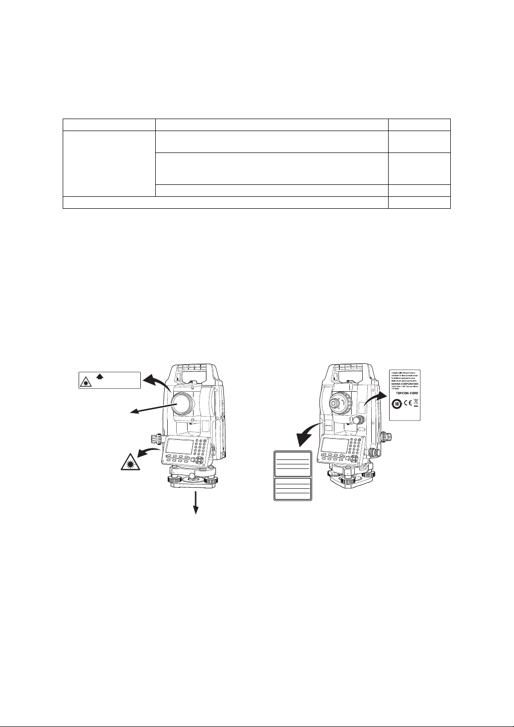
LASER SAFETY INFORMATION
࣮ࣞࢨගࡢฟཱྀ
AVOID EXPOSURE-Laser radiation
is emitted from this aperture.
┠ࡢ┤᥋⿕ࡤࡃࢆ㑊ࡅࡿࡇ
ࢡࣛࢫ5࣮ࣞࢨ〇ရ
-,6&
LASER RADIATION
AVOID DIRECT EYE EXPOSURE
0$;P:/'QP
MAX 5mW LD 625-695nm
CLASS3R LASER PRODUCT
IEC 60825-1 Ed.3.0: 2014
࣮ࣞࢨග
Laser beam
emitted
from here
Laser beam
emitted
from here*
GM is classified as the following class of Laser Product according to IEC Standard Publication 60825-1 Ed.3.0:
2014 and United States Government Code of Federal Regulation FDA CDRH 21CFR Part 1040.10 and 1040.11
(Complies with FDA performance standards for laser products except for deviations pursuant to Laser Notice
No.50, dated June 24, 2007.)
Device Laser class
Light beam used for measurement
(When reflectorless measurement is selected in Config mode)
EDM device
in objective lens
Light beam used for measurement
(When prism or reflective sheet is selected as target in Config
mode)
Laser-pointer Class 3R
Laser plummet (option) *1 Class 2
*1: Laser plummet is available as a factory option depending on the country or the area where the
instrument is purchased.
• EDM device is classified as Class 3R Laser Product when reflectorless measurement is selected. When the
prism or reflective sheet is selected in Config mode as target, the output is equivalent to the safer class 1.
Warning
• Use of controls or adjustments or performance of procedures other than those specified herein may result in
hazardous radiation exposure.
• Follow the safety instructions on the labels attached to the instrument as well as in this manual to ensure
safe use of this laser product.
Class 3R
Class 1
• Never intentionally point the laser beam at another person.The laser beam is injurious to the eyes and skin.
If an eye injury is caused by exposure to the laser beam, seek immediate medical attention from a licensed
ophthalmologist.
• Do not stare at the laser beam. Doing so could cause permanent eye damage.
• Never look at the laser beam through a telescope, binoculars or other optical instruments. Doing so could
cause permanent eye damage.
• Do not look directly into the laser beam source. Doing so could cause permanent eye damage.
• Sight targets so that laser beam does not stray from them.
*: only for instruments with laser plummet (option)
x
Caution
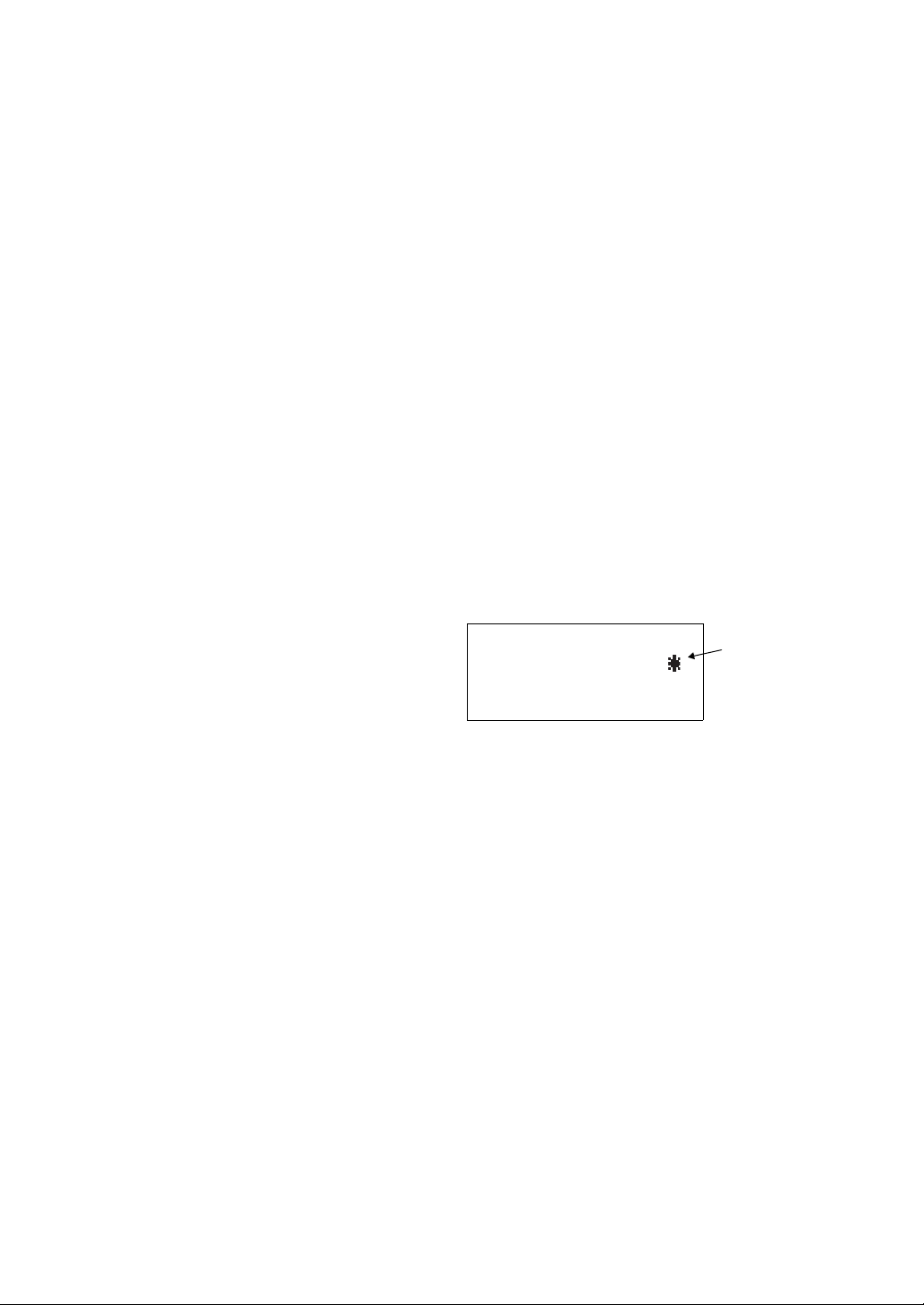
TILT SENSOR:[XY-ON]
X:-0°00'25"
Y: 0°00'20"
X-ON XY-ON OFF ---
Symbol mark
• Perform checks at start of work and periodic checks and adjustments with the laser beam emitted under
normal conditions.
• When the instrument is not being used, turn OFF the power.
• When disposing of the instrument, destroy the battery connector so that the laser beam cannot be emitted.
• Operate the instrument with due caution to avoid injuries that may be caused by the laser beam
unintentionally striking a person in the eye. Avoid setting the instrument at heights at which the path of the
laser beam may strike pedestrians or drivers at head height.
• Never point the laser beam at mirrors, windows or surfaces that are highly reflective. The reflected laser
beam could cause serious injury.
• After using the Laser-pointer function, be sure to turn OFF the emission of the laser beam.
• Only those who have been received training as per the following items shall use this product.
• Read the Operator’s manual for usage procedures for this product.
• Hazardous protection procedures (read this chapter).
• Requisite protective gear (read this chapter).
• Accident reporting procedures (stipulate procedures beforehand for transporting the injured and
contacting physicians in case there are laser induced injuries).
• Persons working within the range of the laser beam are advised to wear eye protection which corresponds to
the laser wavelength of the instrument being used.
• Areas in which the laser is used should be posted with a standard laser warning sign.
Symbol mark while the laser is emitting
The following symbol mark will appear at the right side
of the second line.
xi

Contents
1 NOMENCLATURE AND FUNCTIONS . . . . . . . . . . . . . . . . . . . . . . . . . . 1-1
1.1 Nomenclature . . . . . . . . . . . . . . . . . . . . . . . . . . . . . . . . . . . . . . . . . . . . . . . . . . . . . . . . 1-1
1.2 Display . . . . . . . . . . . . . . . . . . . . . . . . . . . . . . . . . . . . . . . . . . . . . . . . . . . . . . . . . . . . . 1-3
1.3 Operating Key. . . . . . . . . . . . . . . . . . . . . . . . . . . . . . . . . . . . . . . . . . . . . . . . . . . . . . . . 1-4
1.4 Function Key (Soft Key) . . . . . . . . . . . . . . . . . . . . . . . . . . . . . . . . . . . . . . . . . . . . . . . . 1-5
1.5 Starkey mode . . . . . . . . . . . . . . . . . . . . . . . . . . . . . . . . . . . . . . . . . . . . . . . . . . . . . . . . 1-7
1.6 Serial signal RS-232C connector . . . . . . . . . . . . . . . . . . . . . . . . . . . . . . . . . . . . . . . . . 1-9
1.7 Bluetooth communication (Only for Bluetooth function built-in model) . . . . . . . . . . . . . 1-9
2 PREPARATION FOR MEASUREMENT . . . . . . . . . . . . . . . . . . . . . . . . . 2-1
2.1 Power Switch Key ON . . . . . . . . . . . . . . . . . . . . . . . . . . . . . . . . . . . . . . . . . . . . . . . . . 2-1
2.2 Battery Power Remaining Display . . . . . . . . . . . . . . . . . . . . . . . . . . . . . . . . . . . . . . . . 2-2
2.3 Vertical and Horizontal Angle Tilt Correction . . . . . . . . . . . . . . . . . . . . . . . . . . . . . . . . 2-3
2.4 How to Enter Alphanumeric Characters . . . . . . . . . . . . . . . . . . . . . . . . . . . . . . . . . . . . 2-5
2.5 Setting Instrument Up for Measurement. . . . . . . . . . . . . . . . . . . . . . . . . . . . . . . . . . . . 2-8
2.5.1 Centering . . . . . . . . . . . . . . . . . . . . . . . . . . . . . . . . . . . . . . . . . . . . . . . . . . . . . . . 2-8
2.5.2 Levelling. . . . . . . . . . . . . . . . . . . . . . . . . . . . . . . . . . . . . . . . . . . . . . . . . . . . . . . 2-10
2.6 FOCUSSING AND TARGET SIGHTING . . . . . . . . . . . . . . . . . . . . . . . . . . . . . . . . . . 2-11
3 ANGLE MEASUREMENT . . . . . . . . . . . . . . . . . . . . . . . . . . . . . . . . . . . . 3-1
3.1 Measuring Horizontal Angle Right and Vertical Angle . . . . . . . . . . . . . . . . . . . . . . . . . 3-1
3.2 Switching Horizontal Angle Right/Left. . . . . . . . . . . . . . . . . . . . . . . . . . . . . . . . . . . . . . 3-1
3.3 Measuring from the Required Horizontal Angle . . . . . . . . . . . . . . . . . . . . . . . . . . . . . . 3-2
3.3.1 Setting by Holding the Angle . . . . . . . . . . . . . . . . . . . . . . . . . . . . . . . . . . . . . . . . 3-2
3.3.2 Setting a Horizontal Angle from the Keys . . . . . . . . . . . . . . . . . . . . . . . . . . . . . . 3-2
3.4 Vertical Angle Percent Grade(%) Mode . . . . . . . . . . . . . . . . . . . . . . . . . . . . . . . . . . . . 3-3
3.5 Repetition Angle Measurement . . . . . . . . . . . . . . . . . . . . . . . . . . . . . . . . . . . . . . . . . . 3-3
3.6 Buzzer Sounding for Horizontal Angle 90° Increments. . . . . . . . . . . . . . . . . . . . . . . . . 3-4
3.7 Compasses (vertical angle) . . . . . . . . . . . . . . . . . . . . . . . . . . . . . . . . . . . . . . . . . . . . . 3-5
4 DISTANCE MEASUREMENT . . . . . . . . . . . . . . . . . . . . . . . . . . . . . . . . . 4-1
4.1 Setting of the Atmospheric Correction . . . . . . . . . . . . . . . . . . . . . . . . . . . . . . . . . . . . . 4-2
4.2 Setting of the Correction for Prism Constant . . . . . . . . . . . . . . . . . . . . . . . . . . . . . . . . 4-2
4.3 Distance Measurement (Continuous Measurement) . . . . . . . . . . . . . . . . . . . . . . . . . . 4-2
4.4 Distance Measurement (N-time Measurement/Single Measurement) . . . . . . . . . . . . . 4-3
4.5 Fine Mode/Tracking Mode/Coarse Mode . . . . . . . . . . . . . . . . . . . . . . . . . . . . . . . . . . . 4-4
4.6 Stake Out (S.O) . . . . . . . . . . . . . . . . . . . . . . . . . . . . . . . . . . . . . . . . . . . . . . . . . . . . . . 4-5
4.7 Offset Measurement . . . . . . . . . . . . . . . . . . . . . . . . . . . . . . . . . . . . . . . . . . . . . . . . . . . 4-6
4.7.1 Angle Offset . . . . . . . . . . . . . . . . . . . . . . . . . . . . . . . . . . . . . . . . . . . . . . . . . . . . . 4-7
4.7.2 Distance Offset Measurement . . . . . . . . . . . . . . . . . . . . . . . . . . . . . . . . . . . . . . . 4-9
4.7.3 Plane Offset Measurement . . . . . . . . . . . . . . . . . . . . . . . . . . . . . . . . . . . . . . . . 4-11
4.7.4 Column Offset Measurement . . . . . . . . . . . . . . . . . . . . . . . . . . . . . . . . . . . . . . . 4-13
5 COORDINATE MEASUREMENT . . . . . . . . . . . . . . . . . . . . . . . . . . . . . . 5-1
5.1 Setting Coordinate Values of Occupied Point. . . . . . . . . . . . . . . . . . . . . . . . . . . . . . . . 5-1
5.2 Setting Height of the Instrument . . . . . . . . . . . . . . . . . . . . . . . . . . . . . . . . . . . . . . . . . . 5-2
5.3 Setting Height of Target (Prism Height) . . . . . . . . . . . . . . . . . . . . . . . . . . . . . . . . . . . . 5-2
5.4 Execution of Coordinate Measuring . . . . . . . . . . . . . . . . . . . . . . . . . . . . . . . . . . . . . . . 5-3
6 SPECIAL MODE (Menu Mode). . . . . . . . . . . . . . . . . . . . . . . . . . . . . . . . 6-1
6.1 Application Measurement (PROGRAMS). . . . . . . . . . . . . . . . . . . . . . . . . . . . . . . . . . . 6-2
6.1.1 Remote Elevation measurement (REM) . . . . . . . . . . . . . . . . . . . . . . . . . . . . . . . 6-2
6.1.2 Missing Line Measurement (MLM). . . . . . . . . . . . . . . . . . . . . . . . . . . . . . . . . . . . 6-5
6.1.3 Setting Z Coordinate of Occupied Point. . . . . . . . . . . . . . . . . . . . . . . . . . . . . . . . 6-8
6.1.4 Area Calculation. . . . . . . . . . . . . . . . . . . . . . . . . . . . . . . . . . . . . . . . . . . . . . . . . 6-11
6.1.5 Point to Line Measurement . . . . . . . . . . . . . . . . . . . . . . . . . . . . . . . . . . . . . . . . 6-14
6.2 Setting the GRID FACTOR. . . . . . . . . . . . . . . . . . . . . . . . . . . . . . . . . . . . . . . . . . . . . 6-16
6.3 Setting Illumination of Display and Cross Hairs . . . . . . . . . . . . . . . . . . . . . . . . . . . . . 6-17
6.4 Setting Mode 1 . . . . . . . . . . . . . . . . . . . . . . . . . . . . . . . . . . . . . . . . . . . . . . . . . . . . . . 6-18
6.4.1 Setting Minimum Reading . . . . . . . . . . . . . . . . . . . . . . . . . . . . . . . . . . . . . . . . . 6-18
6.4.2 Auto Power Off. . . . . . . . . . . . . . . . . . . . . . . . . . . . . . . . . . . . . . . . . . . . . . . . . . 6-19
6.4.3 Vertical and Horizontal Angle Tilt correction (Tilt ON/OFF) . . . . . . . . . . . . . . . . 6-20
6.4.4 Systematic Error of Instrument Correction . . . . . . . . . . . . . . . . . . . . . . . . . . . . . 6-20
1

6.4.5 Setting RS-232C communication with external device . . . . . . . . . . . . . . . . . . . 6-22
6.4.6 Selecting Communication Port. . . . . . . . . . . . . . . . . . . . . . . . . . . . . . . . . . . . . . 6-23
6.4.7 Confirming the Bluetooth Device Address
(Only for Bluetooth function built-in model) . . . . . . . . . . . . . . . . . . . . . . . . . . . . 6-24
6.4.8 Humidity Input ON/OFF Setting . . . . . . . . . . . . . . . . . . . . . . . . . . . . . . . . . . . . . 6-25
6.4.9 NP-TRK MODE Setting . . . . . . . . . . . . . . . . . . . . . . . . . . . . . . . . . . . . . . . . . . . 6-26
6.4.10 EDM ECO. MODE Setting . . . . . . . . . . . . . . . . . . . . . . . . . . . . . . . . . . . . . . . . 6-27
6.4.11 Volume Setting. . . . . . . . . . . . . . . . . . . . . . . . . . . . . . . . . . . . . . . . . . . . . . . . . 6-28
6.5 Setting Contrast of Display . . . . . . . . . . . . . . . . . . . . . . . . . . . . . . . . . . . . . . . . . . . . . 6-29
6.6 Displaying Instrument Information . . . . . . . . . . . . . . . . . . . . . . . . . . . . . . . . . . . . . . . 6-29
6.7 Road . . . . . . . . . . . . . . . . . . . . . . . . . . . . . . . . . . . . . . . . . . . . . . . . . . . . . . . . . . . . . . 6-30
6.7.1 Inputting Start Point . . . . . . . . . . . . . . . . . . . . . . . . . . . . . . . . . . . . . . . . . . . . . . 6-31
6.7.2 Inputting Road Data . . . . . . . . . . . . . . . . . . . . . . . . . . . . . . . . . . . . . . . . . . . . . . 6-32
6.7.3 Searching Data . . . . . . . . . . . . . . . . . . . . . . . . . . . . . . . . . . . . . . . . . . . . . . . . . 6-36
6.7.4 Editing Data . . . . . . . . . . . . . . . . . . . . . . . . . . . . . . . . . . . . . . . . . . . . . . . . . . . . 6-36
6.7.5 Setting OCC and BS . . . . . . . . . . . . . . . . . . . . . . . . . . . . . . . . . . . . . . . . . . . . . 6-37
6.7.6 Stake-out Road . . . . . . . . . . . . . . . . . . . . . . . . . . . . . . . . . . . . . . . . . . . . . . . . . 6-39
6.7.7 Selecting a File . . . . . . . . . . . . . . . . . . . . . . . . . . . . . . . . . . . . . . . . . . . . . . . . . 6-40
6.7.8 Initializing ROAD data . . . . . . . . . . . . . . . . . . . . . . . . . . . . . . . . . . . . . . . . . . . . 6-40
7 DATA COLLECTION. . . . . . . . . . . . . . . . . . . . . . . . . . . . . . . . . . . . . . . . 7-1
7.1 Preparation . . . . . . . . . . . . . . . . . . . . . . . . . . . . . . . . . . . . . . . . . . . . . . . . . . . . . . . . . . 7-3
7.1.1 Selecting a File for Data Collection . . . . . . . . . . . . . . . . . . . . . . . . . . . . . . . . . . . 7-3
7.1.2 Selecting a Coordinate File for Data Collection . . . . . . . . . . . . . . . . . . . . . . . . . . 7-4
7.1.3 Occupied Point and Backsight Point . . . . . . . . . . . . . . . . . . . . . . . . . . . . . . . . . . 7-5
7.2 Operational Procedure of DATA COLLECT . . . . . . . . . . . . . . . . . . . . . . . . . . . . . . . . . 7-7
7.2.1 Searching the recorded data . . . . . . . . . . . . . . . . . . . . . . . . . . . . . . . . . . . . . . . . 7-8
7.2.2 Entering PCODE / ID using PCODE Library . . . . . . . . . . . . . . . . . . . . . . . . . . . . 7-8
7.2.3 Entering PCODE / ID from the list of PCODE . . . . . . . . . . . . . . . . . . . . . . . . . . . 7-9
7.3 Data Collect Offset Measurement mode. . . . . . . . . . . . . . . . . . . . . . . . . . . . . . . . . . . 7-10
7.3.1 Angle Offset Measurement . . . . . . . . . . . . . . . . . . . . . . . . . . . . . . . . . . . . . . . . 7-10
7.3.2 Distance Offset Measurement . . . . . . . . . . . . . . . . . . . . . . . . . . . . . . . . . . . . . . 7-12
7.3.3 Plane Offset Measurement . . . . . . . . . . . . . . . . . . . . . . . . . . . . . . . . . . . . . . . . 7-14
7.3.4 Column Offset Measurement . . . . . . . . . . . . . . . . . . . . . . . . . . . . . . . . . . . . . . . 7-16
7.4 NEZ Auto Calculation . . . . . . . . . . . . . . . . . . . . . . . . . . . . . . . . . . . . . . . . . . . . . . . . . 7-17
7.5 Point to Line Measurement. . . . . . . . . . . . . . . . . . . . . . . . . . . . . . . . . . . . . . . . . . . . . 7-18
7.5.1 To change to the point to line measurement . . . . . . . . . . . . . . . . . . . . . . . . . . . 7-18
7.5.2 Executing a point to line measurement . . . . . . . . . . . . . . . . . . . . . . . . . . . . . . . 7-19
7.6 Editing PCODE Library [PCODE INPUT] . . . . . . . . . . . . . . . . . . . . . . . . . . . . . . . . . . 7-20
7.7 Setting Parameter of Data Collect [CONFIG.] . . . . . . . . . . . . . . . . . . . . . . . . . . . . . . 7-21
8 LAYOUT . . . . . . . . . . . . . . . . . . . . . . . . . . . . . . . . . . . . . . . . . . . . . . . . . 8-1
8.1 Preparation . . . . . . . . . . . . . . . . . . . . . . . . . . . . . . . . . . . . . . . . . . . . . . . . . . . . . . . . . . 8-3
8.1.1 Setting the GRID FACTOR . . . . . . . . . . . . . . . . . . . . . . . . . . . . . . . . . . . . . . . . . 8-3
8.1.2 Selecting Coordinate Data File . . . . . . . . . . . . . . . . . . . . . . . . . . . . . . . . . . . . . . 8-4
8.1.3 Setting Occupied Point . . . . . . . . . . . . . . . . . . . . . . . . . . . . . . . . . . . . . . . . . . . . 8-5
8.1.4 Setting Backsight Point . . . . . . . . . . . . . . . . . . . . . . . . . . . . . . . . . . . . . . . . . . . . 8-7
8.2 Executing a Layout . . . . . . . . . . . . . . . . . . . . . . . . . . . . . . . . . . . . . . . . . . . . . . . . . . . . 8-9
8.2.1 Layout of Coordinates of Point to Line. . . . . . . . . . . . . . . . . . . . . . . . . . . . . . . . 8-11
8.3 Setting a New Point . . . . . . . . . . . . . . . . . . . . . . . . . . . . . . . . . . . . . . . . . . . . . . . . . . 8-12
8.3.1 Side Shot Method . . . . . . . . . . . . . . . . . . . . . . . . . . . . . . . . . . . . . . . . . . . . . . . 8-12
8.3.2 Resection Method . . . . . . . . . . . . . . . . . . . . . . . . . . . . . . . . . . . . . . . . . . . . . . . 8-14
9 MEMORY MANAGER MODE . . . . . . . . . . . . . . . . . . . . . . . . . . . . . . . . . 9-1
9.1 Display Internal Memory Status . . . . . . . . . . . . . . . . . . . . . . . . . . . . . . . . . . . . . . . . . . 9-2
9.2 Searching Data. . . . . . . . . . . . . . . . . . . . . . . . . . . . . . . . . . . . . . . . . . . . . . . . . . . . . . . 9-3
9.2.1 Measured Data Searching . . . . . . . . . . . . . . . . . . . . . . . . . . . . . . . . . . . . . . . . . . 9-3
9.2.2 Coordinate Data Searching . . . . . . . . . . . . . . . . . . . . . . . . . . . . . . . . . . . . . . . . . 9-5
9.2.3 PCODE LIBRARY Searching. . . . . . . . . . . . . . . . . . . . . . . . . . . . . . . . . . . . . . . . 9-6
9.3 File Maintenance . . . . . . . . . . . . . . . . . . . . . . . . . . . . . . . . . . . . . . . . . . . . . . . . . . . . . 9-7
9.3.1 Rename a File . . . . . . . . . . . . . . . . . . . . . . . . . . . . . . . . . . . . . . . . . . . . . . . . . . . 9-8
9.3.2 Searching Data in a File. . . . . . . . . . . . . . . . . . . . . . . . . . . . . . . . . . . . . . . . . . . . 9-8
9.3.3 Deleting a File . . . . . . . . . . . . . . . . . . . . . . . . . . . . . . . . . . . . . . . . . . . . . . . . . . . 9-9
9.4 Coordinate Data Direct Key Input . . . . . . . . . . . . . . . . . . . . . . . . . . . . . . . . . . . . . . . . 9-10
9.4.1 Coordinate data input. . . . . . . . . . . . . . . . . . . . . . . . . . . . . . . . . . . . . . . . . . . . . 9-10
2

9.4.2 PTL (Point to Line) data input . . . . . . . . . . . . . . . . . . . . . . . . . . . . . . . . . . . . . . 9-11
9.5 Delete a Coordinate Data from a File . . . . . . . . . . . . . . . . . . . . . . . . . . . . . . . . . . . . . 9-12
9.6 Editing PCODE Library. . . . . . . . . . . . . . . . . . . . . . . . . . . . . . . . . . . . . . . . . . . . . . . . 9-13
9.7 Data Communications . . . . . . . . . . . . . . . . . . . . . . . . . . . . . . . . . . . . . . . . . . . . . . . . 9-14
9.7.1 Sending Data . . . . . . . . . . . . . . . . . . . . . . . . . . . . . . . . . . . . . . . . . . . . . . . . . . . 9-14
9.7.2 Loading Data . . . . . . . . . . . . . . . . . . . . . . . . . . . . . . . . . . . . . . . . . . . . . . . . . . . 9-16
9.7.3 Setting Parameter of Data Communications . . . . . . . . . . . . . . . . . . . . . . . . . . . 9-17
9.7.4 Confirming the parameters for Bluetooth communication
9.8 Initialization. . . . . . . . . . . . . . . . . . . . . . . . . . . . . . . . . . . . . . . . . . . . . . . . . . . . . . . . . 9-19
(Only for Bluetooth function built-in model) . . . . . . . . . . . . . . . . . . . . . . . . . . . . 9-18
10 SET AUDIO MODE . . . . . . . . . . . . . . . . . . . . . . . . . . . . . . . . . . . . . . . 10-1
11 SETTING THE PRISM CONSTANT VALUE. . . . . . . . . . . . . . . . . . . . 11-1
12 SETTING ATMOSPHERIC CORRECTION. . . . . . . . . . . . . . . . . . . . . 12-1
12.1 Calculation of Atmospheric Correction . . . . . . . . . . . . . . . . . . . . . . . . . . . . . . . . . . . 12-1
12.2 Setting of Atmospheric Correction Value . . . . . . . . . . . . . . . . . . . . . . . . . . . . . . . . . 12-2
13 CORRECTION FOR REFRACTION AND EARTH CURVATURE . . . 13-1
13.1 Distance Calculation Formula. . . . . . . . . . . . . . . . . . . . . . . . . . . . . . . . . . . . . . . . . . 13-1
14 POWER SOURCE AND CHARGING . . . . . . . . . . . . . . . . . . . . . . . . . 14-1
14.1 Battery Charging. . . . . . . . . . . . . . . . . . . . . . . . . . . . . . . . . . . . . . . . . . . . . . . . . . . . 14-1
14.2 Installing/Removing the Battery . . . . . . . . . . . . . . . . . . . . . . . . . . . . . . . . . . . . . . . . 14-2
15 USING USB FLASH DRIVE . . . . . . . . . . . . . . . . . . . . . . . . . . . . . . . . 15-1
15.1 Inserting the USB flash drive . . . . . . . . . . . . . . . . . . . . . . . . . . . . . . . . . . . . . . . . . . 15-1
16 DETACH/ATTACH OF TRIBRACH. . . . . . . . . . . . . . . . . . . . . . . . . . . 16-1
17 SELECTING MODE. . . . . . . . . . . . . . . . . . . . . . . . . . . . . . . . . . . . . . . 17-1
17.1 Items of the Selecting Mode . . . . . . . . . . . . . . . . . . . . . . . . . . . . . . . . . . . . . . . . . . . 17-1
17.2 How to Set Selecting Mode . . . . . . . . . . . . . . . . . . . . . . . . . . . . . . . . . . . . . . . . . . . 17-3
18 CHECKS AND ADJUSTMENTS . . . . . . . . . . . . . . . . . . . . . . . . . . . . . 18-1
18.1 Circular Level . . . . . . . . . . . . . . . . . . . . . . . . . . . . . . . . . . . . . . . . . . . . . . . . . . . . . . 18-1
18.2 Adjustment of Vertical Angle 0 Datum . . . . . . . . . . . . . . . . . . . . . . . . . . . . . . . . . . . 18-2
18.3 Adjustment of Compensation Systematic Error of Instrument . . . . . . . . . . . . . . . . . 18-3
18.4 Reticle. . . . . . . . . . . . . . . . . . . . . . . . . . . . . . . . . . . . . . . . . . . . . . . . . . . . . . . . . . . . 18-5
18.5 Optical Plummet . . . . . . . . . . . . . . . . . . . . . . . . . . . . . . . . . . . . . . . . . . . . . . . . . . . . 18-6
18.6 Additive Distance Constant. . . . . . . . . . . . . . . . . . . . . . . . . . . . . . . . . . . . . . . . . . . . 18-7
18.7 Checking and Adjusting of Laser Plummet*1 . . . . . . . . . . . . . . . . . . . . . . . . . . . . . . 18-8
19 TOP FIELD MODE. . . . . . . . . . . . . . . . . . . . . . . . . . . . . . . . . . . . . . . . 19-1
19.1 MAIN MENU (Major Functions) . . . . . . . . . . . . . . . . . . . . . . . . . . . . . . . . . . . . . . . . 19-1
19.2 JOB. . . . . . . . . . . . . . . . . . . . . . . . . . . . . . . . . . . . . . . . . . . . . . . . . . . . . . . . . . . . . . 19-1
19.2.1 To Create New Job . . . . . . . . . . . . . . . . . . . . . . . . . . . . . . . . . . . . . . . . . . . . . 19-1
19.2.2 To Select Existing Job . . . . . . . . . . . . . . . . . . . . . . . . . . . . . . . . . . . . . . . . . . . 19-2
19.2.3 To Delete Job. . . . . . . . . . . . . . . . . . . . . . . . . . . . . . . . . . . . . . . . . . . . . . . . . . 19-2
19.2.4 When Job is not to be Used. . . . . . . . . . . . . . . . . . . . . . . . . . . . . . . . . . . . . . . 19-3
19.3 SETTING . . . . . . . . . . . . . . . . . . . . . . . . . . . . . . . . . . . . . . . . . . . . . . . . . . . . . . . . . 19-3
19.4 GO TO WORK . . . . . . . . . . . . . . . . . . . . . . . . . . . . . . . . . . . . . . . . . . . . . . . . . . . . . 19-4
19.4.1 To Set Occupied Point and Backsight . . . . . . . . . . . . . . . . . . . . . . . . . . . . . . . 19-4
19.4.2 To Layout . . . . . . . . . . . . . . . . . . . . . . . . . . . . . . . . . . . . . . . . . . . . . . . . . . . . 19-13
19.4.3 To Conduct Ordinary Measurement and to Record Coordinates. . . . . . . . . . 19-14
19.5 DATA MANAGER. . . . . . . . . . . . . . . . . . . . . . . . . . . . . . . . . . . . . . . . . . . . . . . . . . 19-16
19.5.1 To Add Coordinate Data . . . . . . . . . . . . . . . . . . . . . . . . . . . . . . . . . . . . . . . . 19-16
19.5.2 To Delete Coordinate Data . . . . . . . . . . . . . . . . . . . . . . . . . . . . . . . . . . . . . . 19-20
19.5.3 To View Coordinate Data. . . . . . . . . . . . . . . . . . . . . . . . . . . . . . . . . . . . . . . . 19-21
19.5.4 To Edit Coordinate Data . . . . . . . . . . . . . . . . . . . . . . . . . . . . . . . . . . . . . . . . 19-22
19.5.5 To Transfer Coordinate Data . . . . . . . . . . . . . . . . . . . . . . . . . . . . . . . . . . . . . 19-23
20 SPECIAL ACCESSORIES . . . . . . . . . . . . . . . . . . . . . . . . . . . . . . . . . 20-1
21 BATTERY SYSTEM . . . . . . . . . . . . . . . . . . . . . . . . . . . . . . . . . . . . . . 21-1
22 PRISM SYSTEM . . . . . . . . . . . . . . . . . . . . . . . . . . . . . . . . . . . . . . . . . 22-1
3

23 ERROR DISPLAYS . . . . . . . . . . . . . . . . . . . . . . . . . . . . . . . . . . . . . . . 23-1
24 SPECIFICATIONS . . . . . . . . . . . . . . . . . . . . . . . . . . . . . . . . . . . . . . . . 24-1
25 REGULATIONS . . . . . . . . . . . . . . . . . . . . . . . . . . . . . . . . . . . . . . . . . . 25-1
4
1 NOMENCLATURE AND FUNCTIONS
2
1
6
4
3
5
7
8
9
11
10
12
13
14
2
15
16
17
19
18
20
22
21
23
24
25
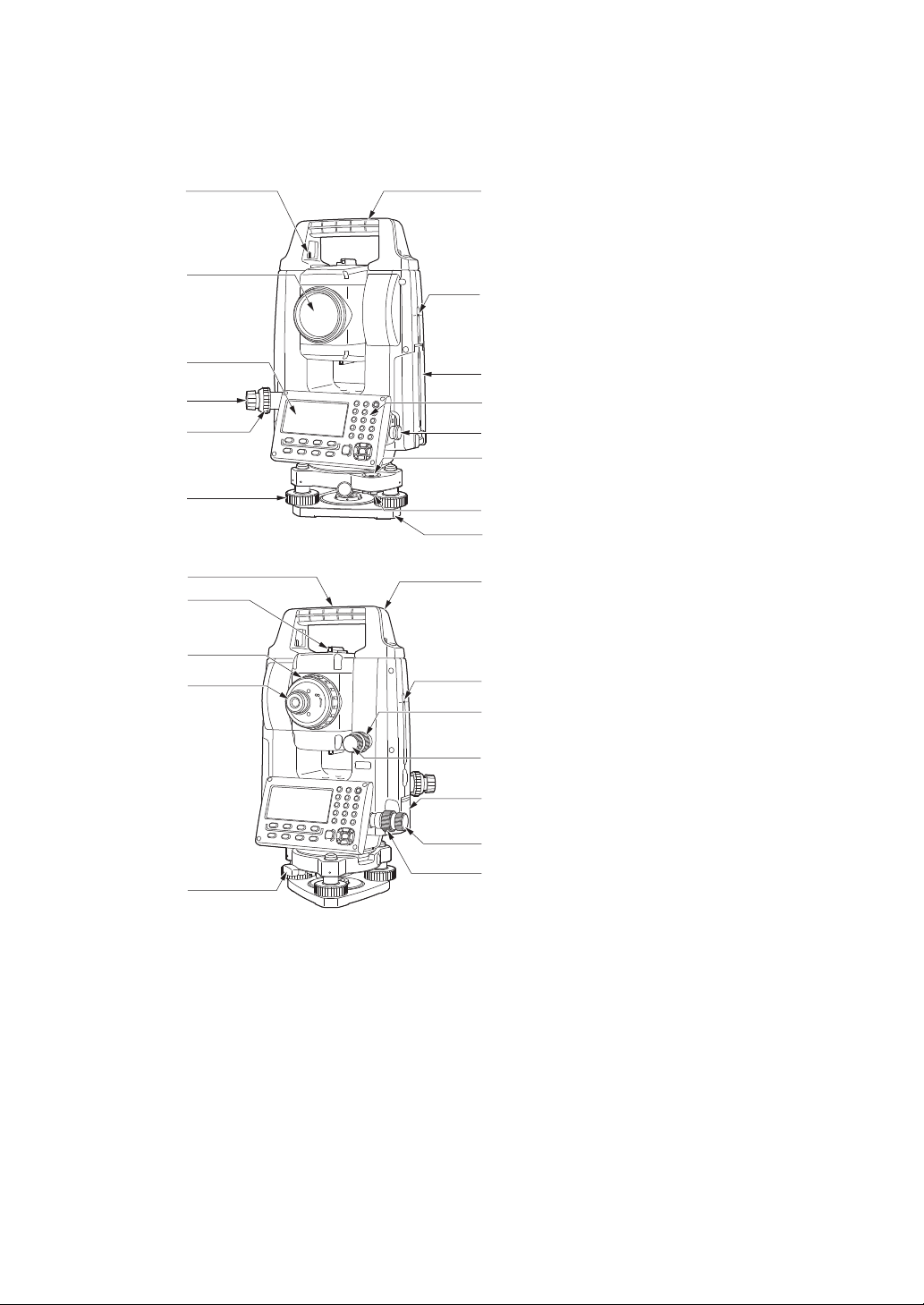
1 NOMENCLATURE AND FUNCTIONS
1.1 Nomenclature
1 Handle
2 Instrument height mark
3 Battery cover
4 Operation panel
5 Serial connector
6 Circular level
7 Circular level adjusting screws
8 Base plate
9 Levelling foot screw
10 Optical plummet focussing ring
11 Optical plummet eyepiece
(10,11: Not included in instruments
with laser plummet)
12 Display unit
13 Objective lens (Includes Laser-pointer
function)
14 Handle locking screw
15 Tubular compass slot
16 Vertical clamp
17 Vertical fine motion screw
18 External interface hatch (USB port/
Reset button)
19 Horizontal fine motion screw
20 Horizontal clamp
21 Tribrach clamp
22 Telescope eyepiece screw
23 Telescope focussing ring
24 Sighting collimator
(Gun sight on GM-55 in Face 2 position)
25 Instrument center mark
1-1
1 NOMENCLATURE AND FUNCTIONS
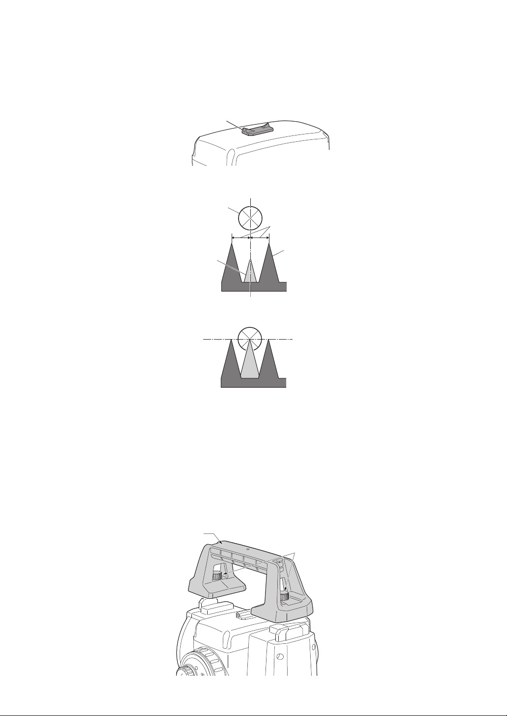
Gun Sight
Target
Front sight
Back sight
Equal intervals
Handle
Handle
locking screw
Sighting collimator
Use sighting collimator to aim the GM in the direction of the measurement point. Turn the
instrument until the triangle in the sighting collimator is aligned with the target.
A gun sight is mounted on Face 2 position of the iM-55. Align the telescope to the direction of the
target in such a way that the gun sight is positioned with the target as shown below. Note that you
see the target at a distance from the gun sight.
Horizontal direction: a position where you can see both the target and back sight at the center of
the front sight's slit.
Vertical direction: a position where you can see the tops of the front sight and back sight at the
same height of the target's center.
Instrument height mark
The height of the GM is as follows:
• 192.5 mm (from tribrach mounting surface to this mark)
• 236 mm (from tribrach dish (TR-103R) to this mark)
"Instrument height" is input when setting instrument station data and is the height from the
measuring point (where GM is mounted) to this mark.
Laser-pointer Function
A target can be sighted with a red laser beam in dark locations without the use of the telescope.
Handle
The carrying handle can be removed from the instrument when the prism is located at the zenith
etc.
To remove it, loosen the handle locking screw.
1-2
1.2 Display
V : 90°10'20"
HR: 120°30'40"
0SET HOLD HSET P1
↓
HR: 120°30'40"
HD* 65.432 m
VD: 12.345 m
MEAS MODE NP/P P1
↓
HR: 120°30'40"
HD* 123.45 f
VD: 12.34 f
MEAS MODE NP/P P1
↓
HR: 120°30'40"
HD* 123.04.6f
VD: 12.03.4f
MEAS MODE NP/P P1
↓
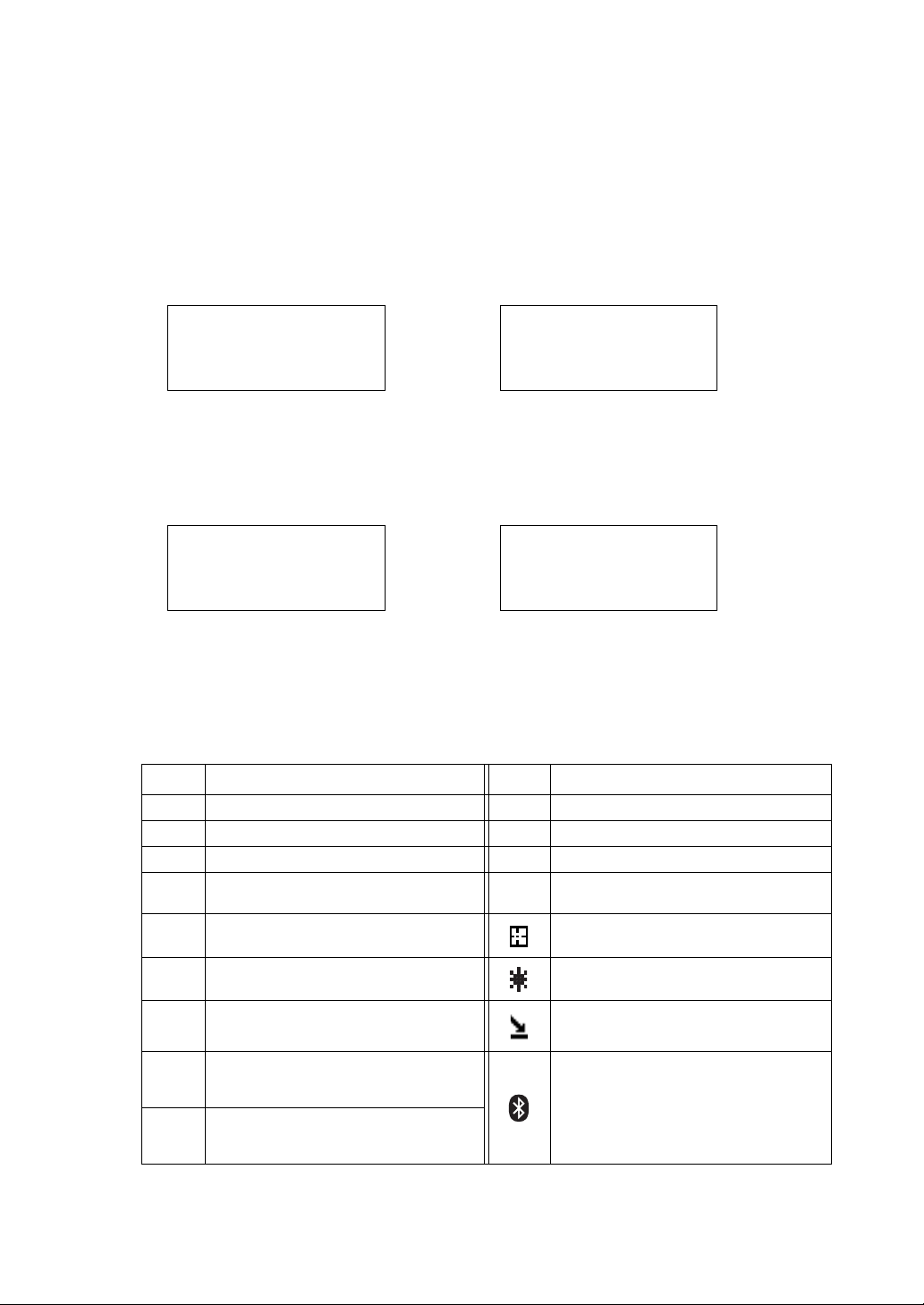
Display
The display uses a graphic LCD which has 4 lines and 20 characters per line. In general, the upper
three lines display measured data, and the bottom line displays the soft key function which changes
with the measuring mode.
Contrast and Illumination
The contrast and illumination of display window are adjusted. See Chapter 6 “SPECIAL MODE
(Menu Mode)” or section 1.5 “Starkey mode”.
Example
1 NOMENCLATURE AND FUNCTIONS
Angle measurement mode
V-angle : 90°10’20”
H-angle : 120°30’40”
Feet unit
Horizontal-angle : 120°30’40”
Horizontal distance : 123.45 ft
Relative elevation : 12.34 ft
Distance measurement mode
Horizontal-angle : 120°30’40”
Horizontal distance : 65.432 m
Relative elevation : 12.345 m
Feet and inch unit
Horizontal-angle : 120°30’40”
Horizontal distance : 123 ft 4 in 6/8 in
Relative elevation : 12 ft 3 in 4/8 in
Display marks
Display Contents Display Contents
VV-angle∗ EDM working
HR H-angle right m Meter unit
HL H-angle left f Feet unit / Feet and inch unit
HD Horizontal distance
N
P
Non-prism mode
VD Relative elevation Sheet mode
SD Slope distance Laser emitting mark
N
E E coordinate
Z Z coordinate
N coordinate
See Section 6.4.9 “NP-TRK
Bluetooth is under communication.
(This symbol mark of the Bluetooth will
be displayed above the battery mark
when the GM is in the state which can
be communicated by Bluetooth.)
NP-TRK mode
MODE Setting”.
1-3
1 NOMENCLATURE AND FUNCTIONS
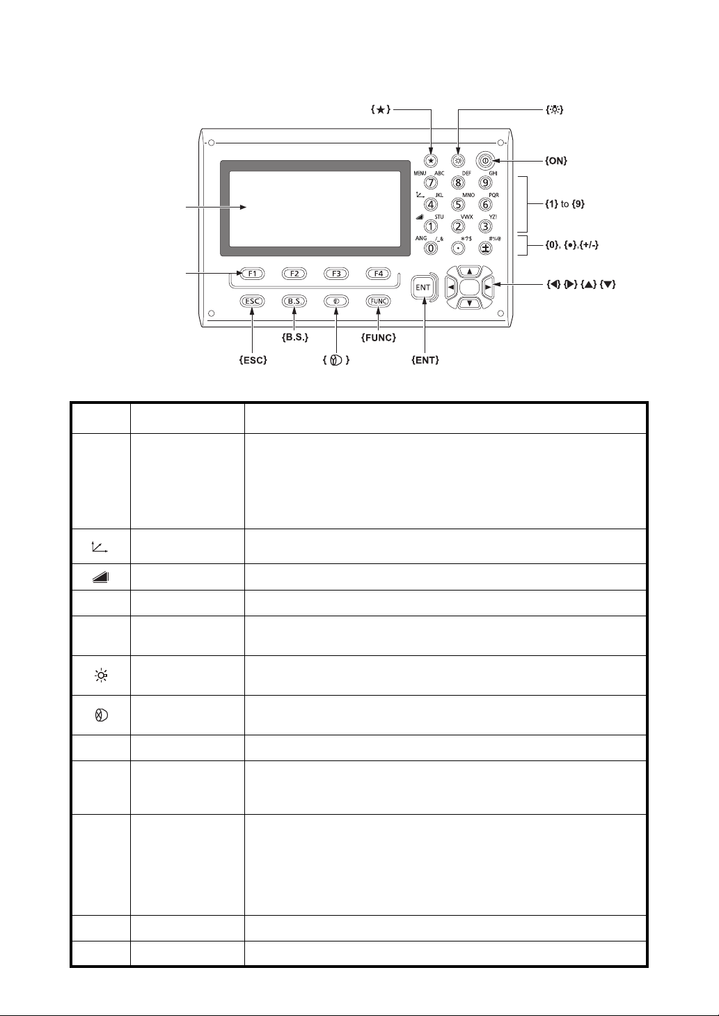
Softkey selection
Display unit
Star key
Power key
Illumination key
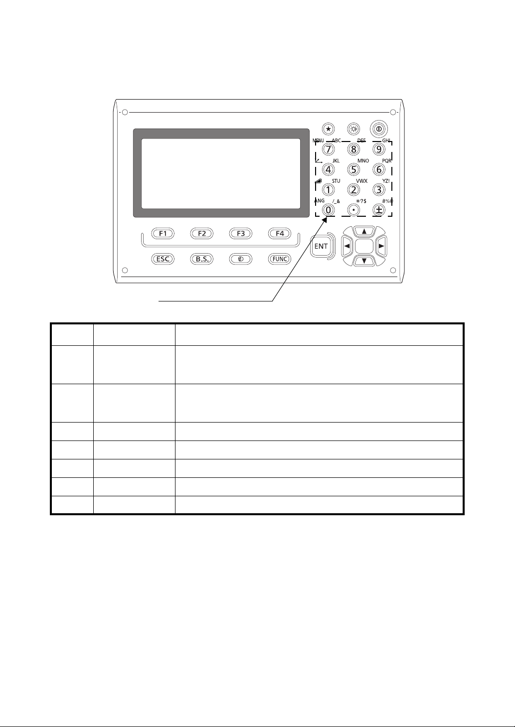
1.3 Operating Key
Keys Name of Key Function
Switches to Starkey mode
This mode is used for each presetting or displaying as follows.
{} Starke y
1 Contrast of the display, 2 Reticle illumination, 3 Laser pointer, 4 Tilt
correction, 5 Set audio mode, 6 Laser Plummet
• Press {} during Starkey mode to go to the Tilt Screen.
For levelling procedure: see Section 2.5.2 “Levelling”.
{}
{}
{ANG} Angle meas.key Switches to angle measurement mode
{MENU} Menu key
{}
{}
{FUNC} Function key Switches Starkey mode pages (Laser plummet mounted model only)
{0} – {9} /
{.} / {±}
{ESC} Escape key
{B.S.} Backspace key Delete a character on the left
Coordinate
meas.key
Distance meas.key Switches to distance measurement mode
Illumination key
Tar g et k e y
Alphanumeric
characters key
Switches to coordinate measurement mode
Switches to menu mode
Starts measurement applications and performs various settings
Lights up the display unit and key
Switches the screen/key backlight and Reticle illumination ON/OFF
Switches between target types (prism mode/Sheet mode/Non-prism mode
(Reflectorless mode))
Input letters/figures
For entering alphanumeric characters, see Section 2.4 “How to
Enter Alphanumeric Characters”.
Returns to the measurement mode or previous layer mode from the
mode set
Switches to data collection mode or layout mode directly from the
normal measurement mode
It is also possible to use as Record key in normal measurement mode.
For selecting function of Escape key, see Chapter 17 “SELECTING MODE” .
{ENT} Enter key Selects/accepts input word/value
1-4
1 NOMENCLATURE AND FUNCTIONS
H-BZ R/L CMPS P3
↓
TILT REP V% P2
↓
V: 90°10'20"
HR: 120°30'40"
0SET HOLD HSET P1
↓
{F1} {F2} {F3} {F4}
Soft keys
--- m/f/i --- P3
↓
OFSET S.O S/A P2
↓
HR: 120°30'40"
HD*[r] << m
VD: m
MEAS MODE NP/P P1
↓
OFSET m/f/i S/A P3
↓
R.HT INSHT OCC P2
↓
N: 123.456 m
E: 34.567 m
Z: 78.912 m
MEAS MODE NP/P P1
↓
Keys Name of Key Function
Turns ON/OFF of power source (Press and hold: About 1 second)
{}
Power key
• In some cases, it may take longer until Power OFF.
• Do not remove the battery until the display turns off. Doing so will cause
data stored in the GM to be lost.
{F1} – {F4}
Soft key
(Function key)
Respond to the message displayed.
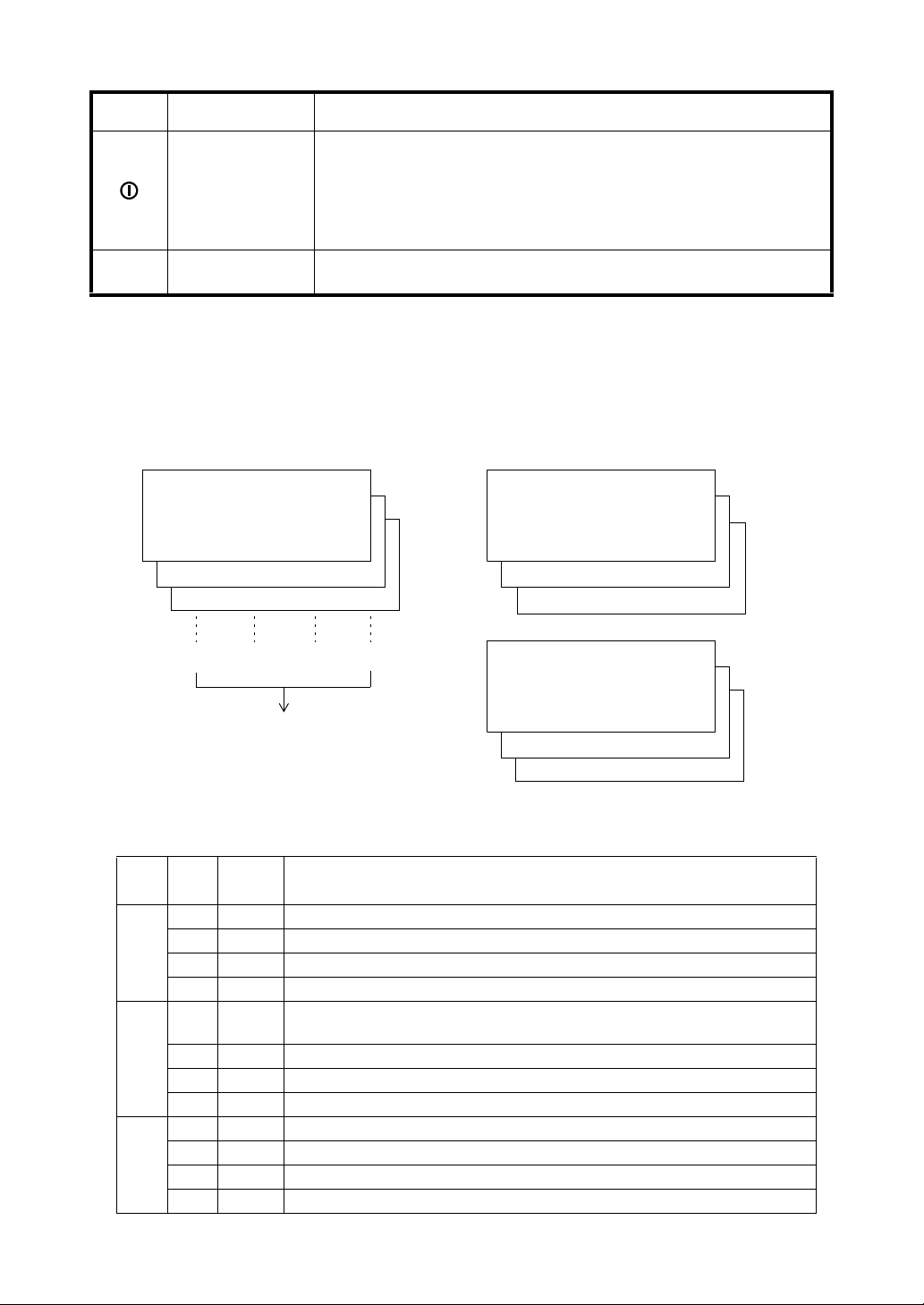
1.4 Function Key (Soft Key)
The Soft Key message is displayed at the bottom line of display. The functions are according to the
displayed message.
Angle measurement mode Distance measurement mode
Coordinates measurement mode
Angle measurement
Page
Soft
key
{F1} 0SET Angle of Horizontal is set to 0°00'00"
{F2} HOLD Hold the horizontal angle.
1
{F3} HSET Sets a required horizontal angle by entering numerals.
{F4} P1
{F1} TILT
{F2} REP Repetition angle measurement mode
2
{F3} V% Vertical angle percent grade(%) mode
{F4} P2
{F1} H-BZ Sets the buzzer sound for every horizontal angle 90°.
{F2} R/L Switches R/L rotation of horizontal angle.
3
{F3} CMPS Switches the COMPASS ON/OFF of vertical angle.
{F4} P3
Display
mark
Function
↓
The function of soft keys is shown on next page (P2).
Setting Tilt Correction
If ON, the display shows tilt correction value.
↓
The function of soft keys is shown on next page (P3).
↓
The function of soft keys is shown on next page (P1).
1-5

Distance measurement mode
{F1} MEAS Start measuring
{F2} MODE Sets a measuring mode, Fine/Coarse/Tracking.
1
{F3} NP/P Switches Non-prism mode, prism mode or Sheet mode.
{F4} P1
↓
The function of soft keys is shown on next page (P2).
{F1} OFSET Select Off-set measurement mode.
{F2} S.O Select Stake out measurement mode.
2
{F3} S/A Select Set audio mode.
{F4} P2
{F2} m/f/i Switches meter, feet or feet and inch unit.
3
{F4} P3
↓
The function of soft keys is shown on next page (P3).
↓
The function of soft keys is shown on next page (P1).
Coordinate measurement mode
{F1} MEAS Start measuring.
{F2} MODE Sets a measuring mode, Fine/Coarse/Tracking.
1
{F3} NP/P Switches Non-prism mode, prism mode or Sheet mode.
{F4} P1
{F1} R.HT Sets a prism height by input values.
{F2} INSHT Sets an instrument height by input values.
2
{F3} OCC Sets an instrument coordinate point by input values.
{F4} P2
{F1} OFSET Select Off-set measurement mode.
{F2} m/f/i Switches meter, feet or feet and inch unit.
3
{F3} S/A Select set audio mode.
{F4} P3
↓
The function of soft keys is shown on next page (P2).
↓
The function of soft keys is shown on next page (P3).
↓
The function of soft keys is shown on next page (P1).
1 NOMENCLATURE AND FUNCTIONS
1-6
1 NOMENCLATURE AND FUNCTIONS
V: 77°42'30"
HR: 120°30'40"
0SET HOLD HSET P1
↓
{}
V: 77°42'30"
HR: 120°30'40"
0SET HOLD HSET P1
↓
Tilt
X -3'20"
Y 3'40"
X
Y
OK L-ON
{ESC}
{}{ESC}
* Screen of laser plummet mounted model
{}
{}
or
{} {}
{}
{}
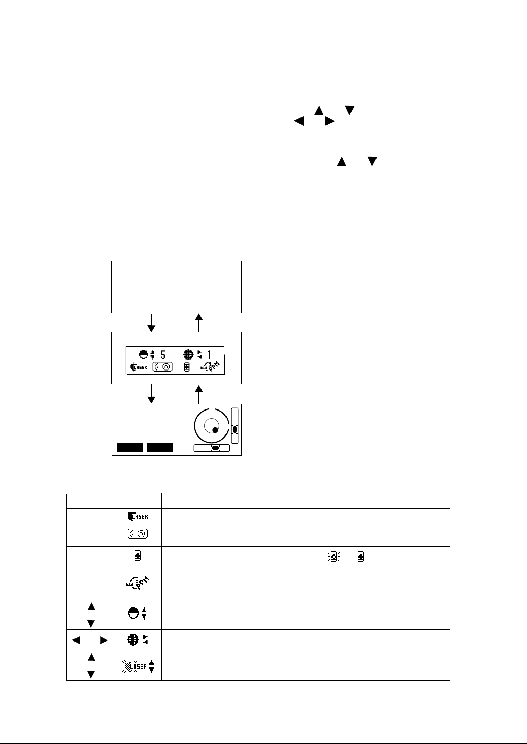
1.5 Starkey mode
Press the {} key to view the instrument options.
The following instrument options can be selected from the {}:
1. Adjustment the contrast of the display (0 to 15 steps) {} or {}
2. Adjustment the reticle illumination (1 to 5 steps) {} or {}
3. Turn the Laser pointer option ON/OFF
4. Setting Tilt Correction
5. S/A (set audio) mode
6. Adjustment the contrast of the laser plummet (1 to 5 steps) {} or {}
7. Turn the Laser plummet option ON/OFF
• Starkey mode does not function when the same function as the function assigned to the Starkey
mode is performed from the main routine.
• Press {} during Starkey mode to go to the Tilt Screen.
For levelling procedure: see Section 2.5.2 “Levelling”.
key
{F1} Turn the Laser plummet option ON/OFF
{F2}
{F3}
{F4}
or
or
Display mark
Setting Tilt Correction
If ON, the display shows tilt correction screen.
Turn the Laser pointer option ON / OFF [ / ]
The light acceptance quantity level for the EDM (SIGNAL), the
atmospheric correction value (PPM) and correction value of prism
constant (PSM / NPM / SHT) are displayed.*1)
Adjust the contrast of the display (0 to 15 steps)
Adjust the Reticle Illumination (1 to 5 steps)
ON/OFF of the reticle illumination is linked with ON/OFF of the backlight.
Adjust the laser plummet brightness (1 to 5 steps)
(displayed only when the laser plummet is ON)
1-7
Function
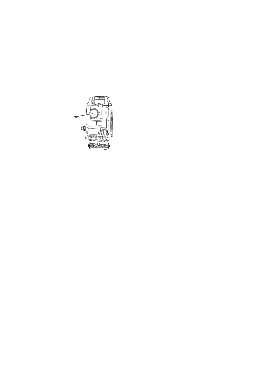
1 NOMENCLATURE AND FUNCTIONS
Laser aperture
Adjustment the contrast (0 to 15) of the display
This enable you to adjust the contrast of the display.
Press the up or down arrow keys to adjust the contrast.
Adjustment the reticle illumination (1 to 5)
This enable you to adjust the reticle illumination.
Press the right or left arrow keys to adjust the reticle illumination.
The switch of reticle illumination will be interlocked with the switch of display backlight.
Lighting and Extinguishing of Laser Pointer
Whenever the {F3} key is pressed, the laser pointer will light up or be extinguished, in that order.
The laser pointer assists with collimation by radiating visible laser light from the objective lens to the
target.
• The laser pointer indicates the approximate collimation position of the telescope. It does not
indicate the exact collimation position.
• You cannot see the laser pointer when looking through the telescope. Therefore, please look
directly, with the naked eye, at the point indicated by the laser pointer.
• The distance to which the laser pointer can be used will vary with climatic conditions and with
the eyesight of the user.
• When the laser pointer is used, the operating time of internal power source will become short.
Tilt correction
The tilt setting mode performed here will not be memorized after powering OFF. To set TILT
correction in the initialized setting (it is memorized after powering OFF), see Section 6.4.3 “Vertical
and Horizontal Angle Tilt correction (Tilt ON/OFF)”.
Set audio mode
The light acceptance quantity level (Signal level) is displayed in this mode.
When reflected light from the prism is received, a buzzer sounds. This function is good for easy
collimation when the target is difficult to find.
Press the {F4} key to view the set audio screen.
To stop the buzzer, refer to Chapter 17 “SELECTING MODE”.
Also, it is possible to display the signal level in Distance Measuring Mode.
The temperature, pressure, PPM, PSM,NPM and SHT can be viewed in set audio mode.
Refer to Chapter 10 “SET AUDIO MODE”, Chapter 11 “SETTING THE PRISM CONSTANT
VALUE” and Chapter 12 “SETTING ATMOSPHERIC CORRECTION”, for further instructions.
1-8

1 NOMENCLATURE AND FUNCTIONS
1.6 Serial signal RS-232C connector
The serial signal connector is used for connecting the GM with a computer or TOPCON Data Collector,
which enables the computer to receive measured data from the GM or to send preset data of horizontal
angle, etc. to it.
The following data will be output at each mode.
Mode Output
Angle mode (V, HR or HL) (V in percent) V, HR (or HL)
Horizontal distance mode (HR, HD, VD) V, HR, HD, VD
Slope distance mode (V, HR, SD) V, HR, SD, HD
Coordinate mode N, E, Z, HR (or V, HR, SD, N, E, Z)
• The display and the output at the coarse mode are the same as the contents above.
• Output at the tracking mode is displayed as distance data only.
The details necessary for the connection with the GM are obtained from the GM-50 series Interface
Manual which is optionally available. Please refer to the manual.
1.7 Bluetooth communication (Only for Bluetooth function built-in model)
By built-in Bluetooth, it can communicate with Bluetooth instruments by wireless, without connecting a
serial signal connector.
1-9

2 PREPARATION FOR MEASUREMENT
Press the power key
(Press and hold: About 1 second)
V : 90°10'20"
HR: 0°00'00"
0SET HOLD HSET P1
↓
Battery Power Remaining Display
Bluetooth is under communication.
(This symbol mark of the Bluetooth will
be displayed when the total station is in
the sate which can be communicated by
Bluetooth.)
Press the {F1} (OK) key
X
Y
X -3'20"
Y 3'40"
Tilt
L-ONOK
CONTRAST ADJUSTMENT
PSM: 0.0 PPM 0.0
NPM: 0.0 SHT: 0.0
↓
↑ - - - ENTER
2 PREPARATION FOR MEASUREMENT
2.1 Power Switch Key ON
1 Confirm the instrument is leveled.
2 Press the power key.
• Confirm the battery power remaining display. Replace with charged battery or charge when battery
level is low or indicates “ ”.
Contrast adjustment
You can confirm prism constant value (PSM), non-prism constant value (NPM), sheet constant
value (SHT), atmospheric correction value (PPM) and you can also adjust the contrast of the
display when the instrument is turned on.
To display this screen, see Chapter 17 “SELECTING MODE”.
This enables you to adjust the brightness by pressing the {F1} (
To memorize the setting value after powering off, press {F4} (ENTER) key.
• If you are experiencing problems with the software, depress the reset button to reboot the program
forcibly. Use a provided hexagonal wrench (1.3 mm/1.5 mm) or a tapered rod like a pin to depress
down the reset button.
See Section 2.2 “Battery Power Remaining Display”.
↓
) or {F2} (↑) key.
2-1
2 PREPARATION FOR MEASUREMENT
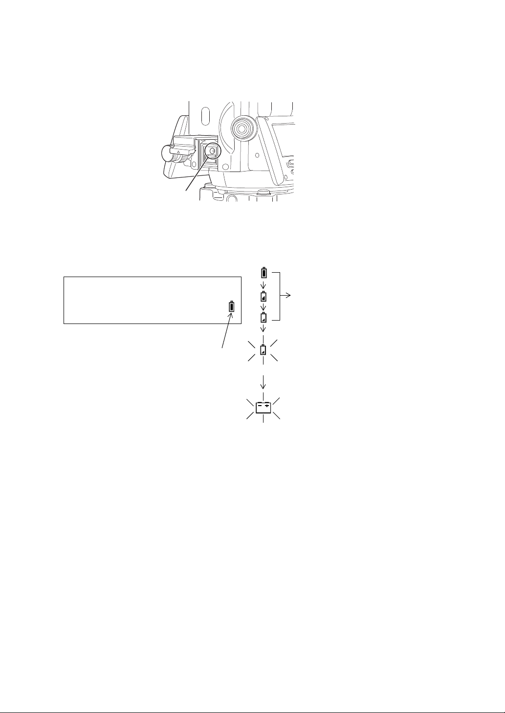
Reset button
Battery power remaining display
Measurement is possible.
The power is poor. The battery
should be recharged or replaced.
Measurement is impossible. Need
to recharge or replace the battery.
Blinking
Other displays disappear.
V : 90°10'20"
HR: 0°00'00"
0SET HOLD HSET P1
↓
Blinking
• Avoid using any sharp implement like a needle. Malfunction of the instrument could result.
• Pressing down the Reset button may result in file and folder data being lost.
2.2 Battery Power Remaining Display
Battery power remaining display indicates the power condition.
• The battery operating time will vary depending on the environmental conditions such as ambient
temperature, charging time, the number of times of charging and discharging etc. It is
recommended for safety to charge the battery beforehand or to prepare spare full charged
batteries.
• For general usage of the battery, see Chapter 14 “POWER SOURCE AND CHARGING”.
• The battery power remaining display shows the power level regarding to the measurement mode
now operating.
The safety condition indicated by the battery power remaining display in the angle measurement
mode does not necessarily assure the battery's ability to be used in the distance measurement
mode.
It may happen that the mode change from the angle mode to the distance mode will stop the
operation because of insufficient battery power for the distance mode which consumes more power
than angle mode.
2-2
2 PREPARATION FOR MEASUREMENT
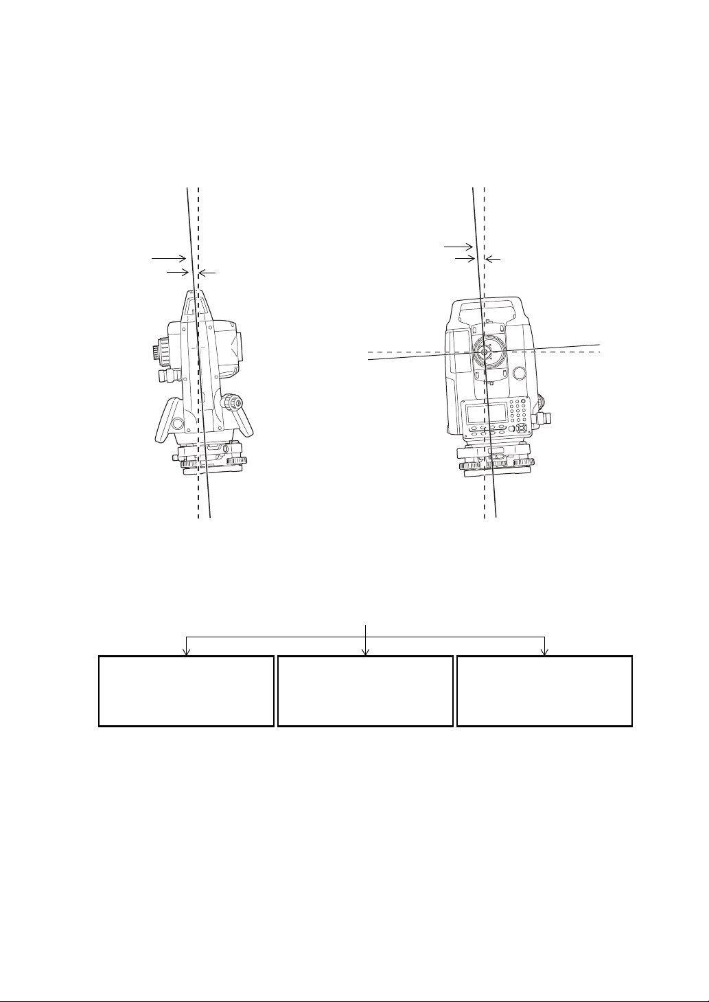
Zenith
Standing axis
Inclination of the standing
axis in the X direction
Zenith
Inclination of the standing
axis in the Y direction
Trunnion axis
Horizontal
Standing axis
V : ° ' "
HR: ° ' "
<X TILT OVER>
V : ° ' "
HR: ° ' "
<Y TILT OVER>
V : ° ' "
HR: ° ' "
<XY TILT OVER>
When the instrument is out of compensation. (TILT OVER)
Standing Axis in the X direction
out of range
Standing Axis in the Y direction
out of range
Standing Axis in the X and Y
directions out of range
2.3 Vertical and Horizontal Angle Tilt Correction
When the tilt sensors are activated, automatic correction of vertical and horizontal angle for
mislevelment is displayed.
To ensure a precise angle measurement, tilt sensors must be turned on. The display can also be used
to fine level the instrument. If the (TILT OVER) display appears the instrument is out of automatic
compensation range and must be leveled manually.
• GM compensates both the vertical angle and the horizontal angle readings due to inclination of the
standing axis in the X and Y directions.
• The display of Vertical or Horizontal angle is unstable when instrument is on an unstable stage or a
windy day. You can turn OFF the auto tilt correction function of V/H angle in this case.
• To set auto tilt correction from the moment that power is on, See Section 6.4.3 “Vertical and
Horizontal Angle Tilt correction (Tilt ON/OFF)”.
2-3
2 PREPARATION FOR MEASUREMENT
V : 90°10'20"
HR: 120°30'40"
0SET HOLD HSET P1
↓
TILT REP V% P2
↓
TILT SENSOR:[XY-ON]
X:-0°00'25"
Y: 0°00'20"
X-ON XY-ON OFF ---
TILT SENSOR: [OFF]
X-ON XY-ON OFF ---
V : 90°10'20"
HR: 120°30'40"
0SET HOLD HSET P1
↓
Setting Tilt Correction by Soft Key
To enable you to select tilt ON/OFF function. setting is not memorized after power is OFF.
[Example] Setting X,Y Tilt OFF
Operating procedure Option Display
1 Press {F4} key to get the function page 2.
{F4}
2 Press {F1} (TILT) key.
In case ON is already selected, the display shows
tilt correction value.
3 Press {F3} (OFF) key.
4 Press {ESC} key.
The setting mode performed here will not be memorized after powering OFF. To set TILT correction in
the initialized setting (it is memorized after powering OFF), See Section 6.4.3 “Vertical and Horizontal
Angle Tilt correction (Tilt ON/OFF)”.
{F1}
{F3}
{ESC}
2-4
2 PREPARATION FOR MEASUREMENT
Alphanumeric characters key
2.4 How to Enter Alphanumeric Characters
This enables you to enter alphanumeric characters such as the instrument height, prism height,
occupied point, backsight point etc.
Keys Name of Key Function
During numeric input, input number of the key.
{0} – {9} Number key
{.} / {±}
{} / {} Cursor key Right and left cursor/Select other option.
} / {} Cursor key Up and down cursor.
{
{ESC} Escape key Cancel the input data.
{B.S.} Backspace key Delete a character on the left.
{ENT} Enter key Select/accept input word/value.
Decimal point key/
Plus-minus sign key
During alphabetic input, input the characters displayed above the key in the
order they are listed.
Input a decimal point/plus or minus sign during numeric input.
During alphabetic input, input the characters displayed above the key in the
order they are listed.
2-5
 Loading...