

Page 1
USER MANUAL
SPECULAR MICROSCOPE
SP-1P
Page 2

Page 3

INTRODUCTION
Thank you for purchasing the TOPCON Specular Microscope SP-1P.
INTENDED USE / INDICATIONS FOR USE
The Topcon Specular Microscope SP-1P is a non-contact ophthalmic microscope, optical
pachymeter, and camera intended for examination of the corneal endothelium and for measurement of the thickness of the cornea.
FEATURES
This instrument features the following:
• The position of the touch panel can be adjusted to accommodate the operator's preferred
position.
• Photography of the corneal endothelium and the measurement of the corneal thickness can
be performed.
• The auto-alignment function ensures quick and easy measurement and photography.
• The cell analysis enables the user to easily get the value of the cell density.
PURPOSE OF THIS MANUAL
This User Manual provides an overview of the basic operation, troubleshooting, checking,
maintenance and cleaning of the TOPCON Specular Microscope SP-1P.
To get the best use of the instrument, read Safety Displays and Safety Cautions.
Keep this Manual at hand for future reference.
• Since this product is a precision instrument, always use and keep it in a normally controlled
living environment, within a temperature range of 10-40°C, humidity levels between 30-90%
and an atmospheric pressure range of 700hPa-1,060hPa.
• The instrument should also be placed away from direct sunlight.
• To ensure smooth operation, install the instrument on a level floor free of vibrations. Also, do
not place anything on the instrument.
• Connect all cables properly before using.
• Use the power at a rated voltage.
• When not in use, switch off the power source and apply the rubber cap and dust cover.
• For accurate Photographing image, take care to keep the Photographing window clean and
free of fingerprints, spots and dust.
[CAUTION] Federal laws restricts this device to the sale by or on the order of a physician.
1
Page 4

Since this product partly uses a program derived from IPA Font, using the product is regarded as
consent to the IPA Font License Agreement v1.0.
For the IPA Font License Agreement v1.0, the following URL.
http://ipafont.ipa.go.jp/ipa_font_license_v1.html
1. No part of this manual may be copied or reprinted, in whole or in part, without prior written permission.
2. The contents of this manual are subject to change without prior notice and without legal obligation.
3. The contents of this manual are correct to the best of our knowledge. Please inform us of any ambiguous or
erroneous descriptions, missing information, etc.
4. Original Instructions
This manual was originally written in English.
©2013 TOPCON CORPORATION
ALL RIGHTS RESERVED
2
Page 5

CONTENTS
INTRODUCTION .....................................................................................................................1
GENERAL SAFETY INFORMATION.......................................................................................6
HOW TO READ THIS MANUAL ..............................................................................................8
GENERAL MAINTENANCE INFORMATION ..........................................................................8
USER MAINTENANCE............................................................................................................8
CLEANING OF PHOTOGRAPHING WINDOW..............................................................8
DISCLAIMERS.........................................................................................................................8
DISPLAYS AND SYMBOLS FOR SAFE USE .........................................................................9
DISPLAYS ......................................................................................................................9
SYMBOLS................................................................................................................................9
POSITIONS OF WARNING AND CAUTION INDICATIONS .................................................10
COMPONENTS
COMPONENT NAMES..........................................................................................................11
COMPOSITION OF PARTS WHICH CONTACT THE HUMAN BODY .................................11
OPERATION METHOD OF CONTROL PANEL....................................................................12
CONTROL PANEL COMPONENTS......................................................................................13
PATIENT SCREEN (DICOM WORK LIST) ..................................................................13
PATIENT SCREEN (ID INPUT)....................................................................................14
HOW TO INPUT A PATIENT ID...................................................................................15
PHOTOGRAPHY SETTING SCREEN .........................................................................17
PHOTOGRAPHING POSITION (SHOWING POSITION OF FFIXATION TARGET)
SELECTING SCREEN .................................................................................................18
CAPUTER SCREEN.....................................................................................................19
PHOTOGRAPHING RESULT SCREEN.......................................................................20
MANUAL EDITING SCREEN .......................................................................................21
THE CHECKING SCREEN IN THE MIDDLE OF PANORAMA PHOTOGRAPHY.......22
RESULT SCREEN FOR PANORAMA PHOTOGRAPHY ............................................22
LIST OF PRINTING ITEMS SCREEN..........................................................................24
PRINTER OUTPUT ...............................................................................................................25
STANDARD ACCESSORIES ................................................................................................27
PREPARATIONS
INSTALLATION .....................................................................................................................28
CONNECTING POWER CABLE ...........................................................................................28
CONNECTING EXTERNAL I/O TERMINALS .......................................................................29
DATA OUTPUT ............................................................................................................29
IMAGEnet .....................................................................................................................30
DATA INPUT ................................................................................................................30
PRINTER PAPER SETTING .................................................................................................31
RECOVERY FROM POWER SAVE STATUS.......................................................................33
ADJUSTING THE CONTROL PANEL POSITION.................................................................33
BASIC OPERATIONS
OPERATION FLOW CHART .................................................................................................34
PREPARATION BEFORE PHOTOGRAPHING (SEQUENCE COURSE) ............................35
TURN THE POWER ON. SET PATIENT ID.................................................................35
SELECT PHOTOGRAPHY POINT AND PATIENT'S EYE...........................................36
PREPARATION OF PATIENT......................................................................................37
PHOTOGRAPHY AND ANALYSIS RESULT DISPLAY ........................................................39
ALIGNMENT AND PHOTOGRAPHY ...........................................................................39
IN MANUAL ALIGNMENT ............................................................................................42
3
Page 6

PRINT-OUT OF PHOTOGRAPHING DATA..........................................................................44
DATA OUTPUT......................................................................................................................44
OPERATION OF AFTER USE...............................................................................................45
OPTIONAL OPERATIONS
FREE STYLE COURSE PHOTOGRAPHY............................................................................46
PANORAMA PHOTOGRAPHY .............................................................................................48
DISPLAYING THE PATIENT ID (PATIENT No.) OR OPERATOR ID ...................................50
FOR DICOM WORK LIST ............................................................................................50
FOR ID INPUT..............................................................................................................50
CELL ANALYSIS IN EDITING MODE ...................................................................................51
OUTPUT TO IMAGEnet SYSTEM.........................................................................................53
INPUT USING USB ...............................................................................................................54
OUTPUT USING LAN............................................................................................................54
SETTING FUNCTIONS ON SETUP SCREEN
OPERATING THE SETUP SCREEN.....................................................................................55
PREPARATONS FOR SETTING .................................................................................55
OUTLINE OF SETUP SCREEN OPERATIONS...........................................................56
RETURNING TO THE MEASUREMENT SCREEN .....................................................58
LIST OF SETUP ITEMS ........................................................................................................59
INITIAL SETTINGS.......................................................................................................59
INTERNAL PRINTER ...................................................................................................60
EXTERNAL PRINTER..................................................................................................61
NETWORK SETTINGS ................................................................................................61
OPERATOR SETTINGS...............................................................................................63
TROUBLESHOOTING
TROUBLE-SHOOTING OPERATIONS .................................................................................64
MESSAGE LIST ...........................................................................................................64
TROUBLE-SHOOTING OPERATIONS........................................................................66
SPECIFICATIONS AND PERFORMANCE
SPECIFICATIONS AND PERFORMANCE ...........................................................................67
GENERAL INFORMATION ON USAGE AND MAINTENANCE
INTENDED PATIENT POPULATION ....................................................................................68
INTENDED USER PROFILE .................................................................................................68
ENVIRONMENTAL CONDITIONS OF USE ..........................................................................68
STORAGE, USAGE PERIOD ................................................................................................68
ENVIRONMENTAL CONDITIONS FOR PACKAGING IN STORAGE ..................................68
ENVIRONMENTAL CONDITIONS FOR PACKAGING IN TRANSPORTATION...................69
ELECTRIC RATING...............................................................................................................69
SAFETY DESIGNATIONS PER IEC 60601-1 STANDARD ..................................................69
DIMENSIONS AND WEIGHT ................................................................................................69
OPERATION PRINCIPLE.....................................................................................................70
CHECKPOINTS FOR MAINTENANCE .................................................................................71
DISPOSAL.............................................................................................................................71
ELECTROMAGNETIC COMPATIBILITY...............................................................................72
REQUIREMENTS FOR THE EXTERNAL DEVICE...............................................................75
PATIENT'S ENVIRONMENT .................................................................................................76
REFERENCE
MAINTENANCE
4
OPTIONAL ACCESSORIES..................................................................................................77
SHAPE OF PLUG ..................................................................................................................77
MAINTAINING ACCURACY ..................................................................................................78
PHOTOGRAPHING WINDOW.....................................................................................78
BRIGHTNESS ADJUSTMENT OF CONTROL PANEL................................................78
Page 7

DAILY CHECKUPS................................................................................................................78
DAILY MAINTENANCE ................................................................................................78
ORDERING CONSUMABLE ITEMS ............................................................................78
USER MAINTENANCE ITEM .......................................................................................79
MANUFACTURER MAINTENANCE ITEMS ................................................................79
PRINTER PAPER JAM.................................................................................................80
SUPPLYING THE CHINREST TISSUE........................................................................81
MAINTENANCE.....................................................................................................................82
CLEANING THE INSTRUMENT...................................................................................82
CLEANING THE PHOTOGRAPHING WINDOW GLASS ............................................82
CLEANING THE COVER .............................................................................................83
CLEANING THE CONTROL PANEL............................................................................83
CLEANING THE FOREHEAD REST AND CHIN REST...............................................83
SP-1P SOFTWARE LICENSE TERMS ....................................................................................84
5
Page 8
GENERAL SAFETY INFORMATION
WARNINGS
Ensuring the Safety of Patients and Operators
When operating the instrument, do not touch the patient's eye or nose.
Handling the cord on this product or cords associated with accessories sold with this product, will expose you to
lead, a chemical known to the State of California to cause birth detects or other reproductive harm. Wash hands
after handling.
Preventing Electric Shocks and Fires
To avoid fire and electric shock, install the instrument in a dry place free of water and other liquids.
To avoid fire and electric shock, do not put cups or other containers with liquids near the instrument.
To avoid electric shocks, do not insert metal objects into the instrument body through the vent holes or gaps.
To avoid fire in the event of an instrument malfunction, immediately turn OFF the power switch " " and disconnect the power plug from the outlet if you see smoke coming from the instrument, etc. Don't install the instrument
where it is difficult to disconnect the power plug from the outlet. Ask your dealer for service.
6
Page 9

CAUTIONS
Ensuring the Safety of Patients and Operators
To avoid injury when operating the up/down button for the chinrest, be careful not to catch the patient's fingers.
The light emitted from this instrument involves potential risk; the longer the irradiation time, the more risk of dam-
age to the eye.
When the instrument operates with the maximum light volume, exposure for more than 2 hours will exceed the
safety guideline.
If a symptom of photosensitive epilepsy appears in a patient during photography, please stop photography immediately.
Preventing Electric Shocks and Fires
To avoid injury by electric shock, do not open the cover. For repair, call your service engineer.
Electromagnetic Compatibility (EMC)
This instrument has been tested (with 100/120/230V) and found to comply with IEC60601-1-2:Ed.3.0:2007. This
instrument radiates radio frequency energy within standard and may affect other devices in the vicinity. If you
have discovered that turning on/off the instrument affects other devices, we recommend you change its position,
keep a proper distance from other devices, or plug it into a different outlet. Please consult your authorized dealer
if you have any additional questions.
7
Page 10

HOW TO READ THIS MANUAL
• Read the instructions on pages 1 to 10 before using the machine.
• Regarding connection to various devices, see "CONNECTING EXTERNAL I/O TERMINALS" on
page 29.
• If you would like an overview of the system, begin by reading "BASIC OPERATIONS"(page 34).
• For setting various functions, see "SETTING FUNCTIONS ON SETUP SCREEN" on page 55.
GENERAL MAINTENANCE INFORMATION
USER MAINTENANCE
To maintain the safety and performance of the equipment, never attempt to repair or perform maintenance.
These tasks should be performed by an authorized service representative.
Maintenance tasks that can be performed by the user are as follows; for details, follow the manual’s instructions.
CLEANING OF PHOTOGRAPHING WINDOW
For details, See "CLEANING THE PHOTOGRAPHING WINDOW GLASS" on page 82.
DISCLAIMERS
• TOPCON is not responsible for damage due to fire, earthquakes, actions or inactions of third persons or other
accidents, or damage due to negligence and misuse by the user and any use under unusual conditions.
• TOPCON is not responsible for damage derived from inability to properly use this equipment, such as loss of
business profits and suspension of business.
• TOPCON is not responsible for damage caused by operations other than those described in this User Manual.
• The device does not provide a diagnosis of any condition or lack thereof or any recommendations for appropriate treatment. The relevant healthcare provider is fully responsible for all diagnosis and treatment decisions
and recommendations.
8
Page 11

DISPLAYS AND SYMBOLS FOR SAFE USE
In order to encourage the safe use of the instrument and to avoid danger to the operator and others as well as damage to properties, warnings are described in the User Manual and marked on the instrument body.
We suggest you thoroughly understand the meaning of the following displays/icons and Safety Cautions, as well as
read the Manual, and strictly observe the instructions.
DISPLAYS
DISPLAY MEANING
A WARNING is provided to alert the user to potential serious outcomes
WARNING
CAUTION
(death, injury, or serious adverse events) to the patient or the user.
A CAUTION is provided to alert the user to use special care necessary
for the safe and effective use of the device. They may include actions to
be taken to avoid effects on patients or users that may not be potentially
life threatening or result in serious injury, but about which the user
should be aware. Cautions are also provided to alert the user to
adverse effects on this device of use or misuse and the care necessary
to avoid such effects.
SYMBOLS
Symbol IEC/ISO Publication Description Description (French)
NOTES
IEC 60417-5032 Alternating Current Courant alternatif
IEC 60417-5008
IEC 60417-5007
IEC 60878-02-02 Type B applied part Partie appliquée du Type B
ISO 7010-W001 General warning sign Symbole d'avertissement général
ISO 7010-M002
A NOTE is provided when additional general information is applicable.
Off (power: disconnection
from the main power supply)
On (power: connection to
the main power supply)
Refer to instruction manual/
booklet
Éteint (courant: coupure avec le
secteur)
Allumé (courant: raccordement
sur le secteur)
Voir le manuel/la brochure
ISO 7000-2497 Date of manufacture Date de fabrication
ISO 7000-2498 Serial number Numéro de série
9
Page 12
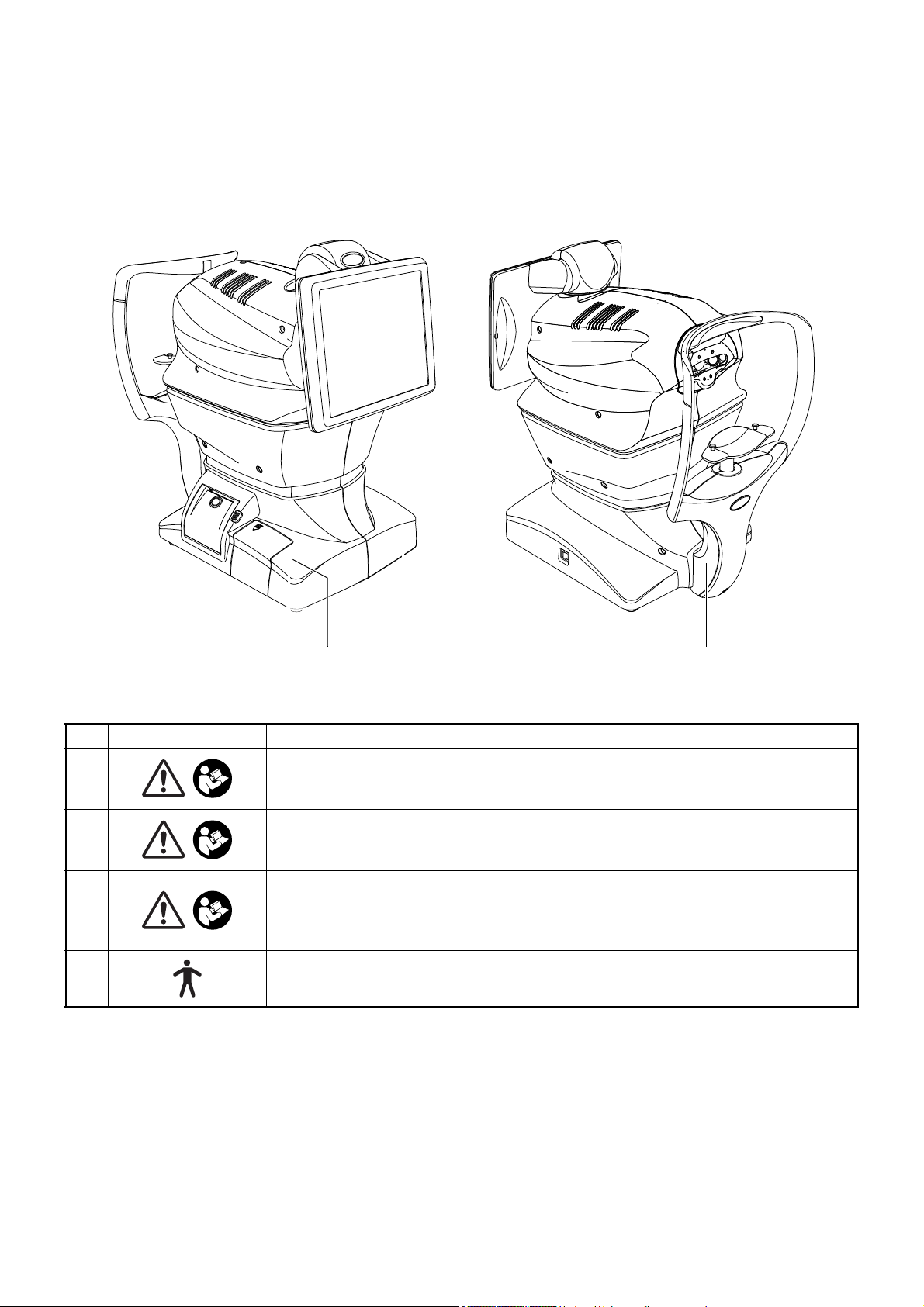
POSITIONS OF WARNING AND CAUTION INDICATIONS
2 1 4
3
To secure safety, this equipment provides warnings.
Correctly use the equipment following these warning instructions. If any of the following marking labels are missing,
please contact your dealer or TOPCON at the address stated on the back cover.
No. Label Meaning
WARNING
1
2
3
4
To avoid injury caused by electric shock, do not open the cover.
Ask your dealer for service.
CAUTION
Be careful not to hit the patient's eyes or nose with the instrument during operation.
The patient may be injured.
CAUTION
When operating the chinrest up/down switch, be careful not to pinch the patient's
hand.
The patient may be injured.
Degree of protection against electric shock:
TYPE B APPLIED PART
10
Page 13

COMPONENTS
Control panel
Photographing head
External I/O terminal cover
Main body Section
Power unit Section
Printer cover open switch
Printer cover
Forehead rest
Eye height mark
Chinrest tissue pin
Chinrest
Chinrest Section
Power inlet
*1
*1
*1: Contacting part (class B)
POWER switch
Photographing
window
COMPONENT NAMES
COMPOSITION OF PARTS WHICH CONTACT THE HUMAN BODY
Forehead rest : Silicone rubber
Chinrest : Acrylonitrile butadiene styrene resin
11
COMPONENTS
Page 14
OPERATION METHOD OF CONTROL PANEL
001081
The control panel is designed as a touch panel for performing various operations and settings.
It displays images and shows information, including set conditions and photographing results.
• The control panel is a touch panel. Do not use any sharp tools; e.g. ball
NOTE
point pen.
• Do not touch two points on a control panel simultaneously.
Tap To select any relevant item.
001081
Touch the control panel softly with a finger.
Drag Under manual alignment.
Continue to press
Used for continuous moving.
(Moving of chinrest and
photographing head)
001081
Continue to touch the screen softly with
a finger.
12
COMPONENTS
Touch and move on screen softly with a
finger.
Page 15
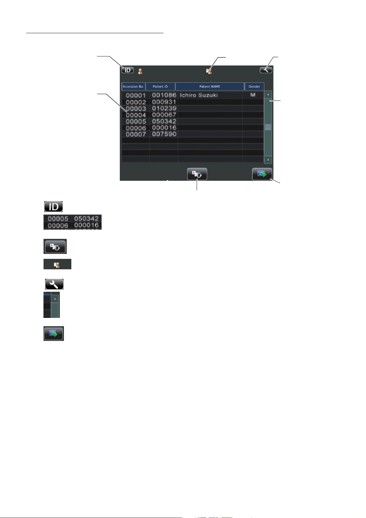
CONTROL PANEL COMPONENTS
Settings button
List update button
Work list
Scroll bar
Next button
Operator ID
Patient ID input change button
PATIENT SCREEN (DICOM WORK LIST)
Patient ID input change button.............A patient screen is switched to ID input.
Work list ...........................The work list which is gained by DICOM MWM (Modality
Work list Management) server is shown.
List update button.................................Select this list to select a patient.
Operator ID........................................When Fixed operator ID is off, the button is tapped and
patient screen appears waiting operator ID input.
Settings button .......................................Displays the Setup screen.
Scroll bar ................................................When there are many work lists, the following hidden list is
displayed.
Next button .............................................Patient selecting is complete and moves to photography set-
ting screen is set.
13
COMPONENTS
Page 16
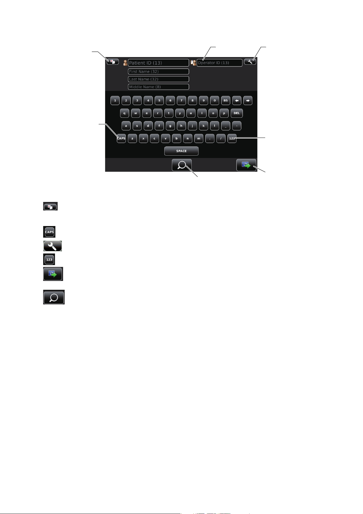
PATIENT SCREEN (ID INPUT)
Caps Lock button
Ten key changeover button
Next button
Settings button
Operator ID
Query patient button
Patient list button
Patient list button.......................................Displays the Patient screen (DICOM work list).
Caps Lock button........................................The letters on software keyboard changes Capital/small.
Ten key changeover button.........................Layout of software keyboard changes QWERTY/Ten key.
This button displays when the setting in the Setup screen is
ON in "Use DICOM" of "NETWORK SETTINGS". (P.61)
Settings button ........................................Displays the Setup screen.
Next button ............................................Patient selecting is complete and photography setting screen
is set.
Query patient button..............................Query the inputted patient in the DICOM work list. This button
displays when the setting in the Setup screen is ON in "Use
DICOM" of "NETWORK SETTINGS". (P.61)
14
COMPONENTS
Page 17
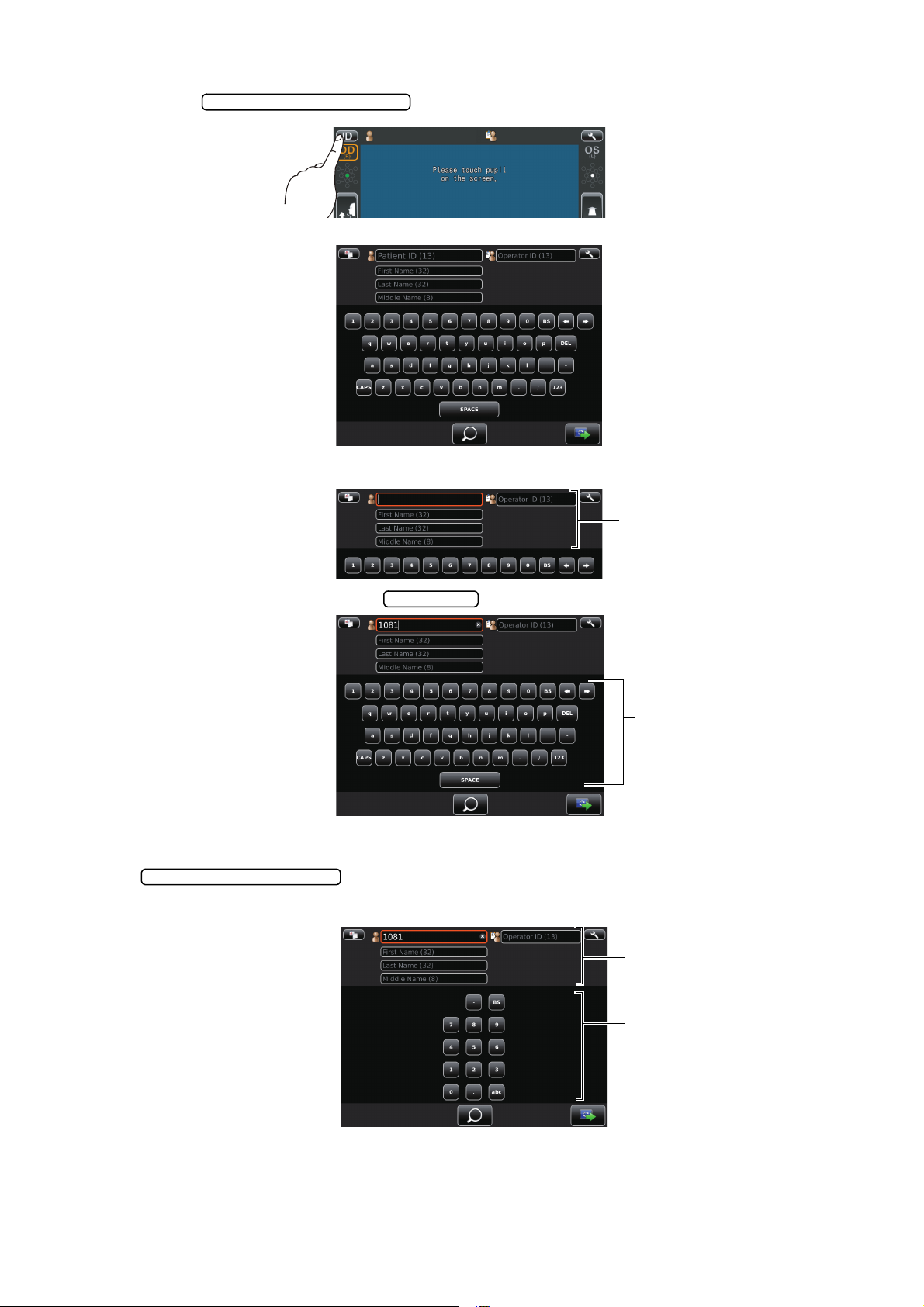
HOW TO INPUT A PATIENT ID
Patient ID input change button
Input window
Input button
Input button
Ten key changeover button
Input button
Input window
1 Tap the on the control panel.
Patient ID input screen is selected.
2 Tap the input window of patient ID to change the frame color to orange.
3 Enter the Patient ID tapping the .
4 If you need to input numeral by ten-key, ten-key input screen appears by tapping the
.
Input in same manner above 2-3.
15
COMPONENTS
Page 18

5 Tap the to return to the capture screen, check that patient ID is updated.
Next button
1081
16
COMPONENTS
Page 19
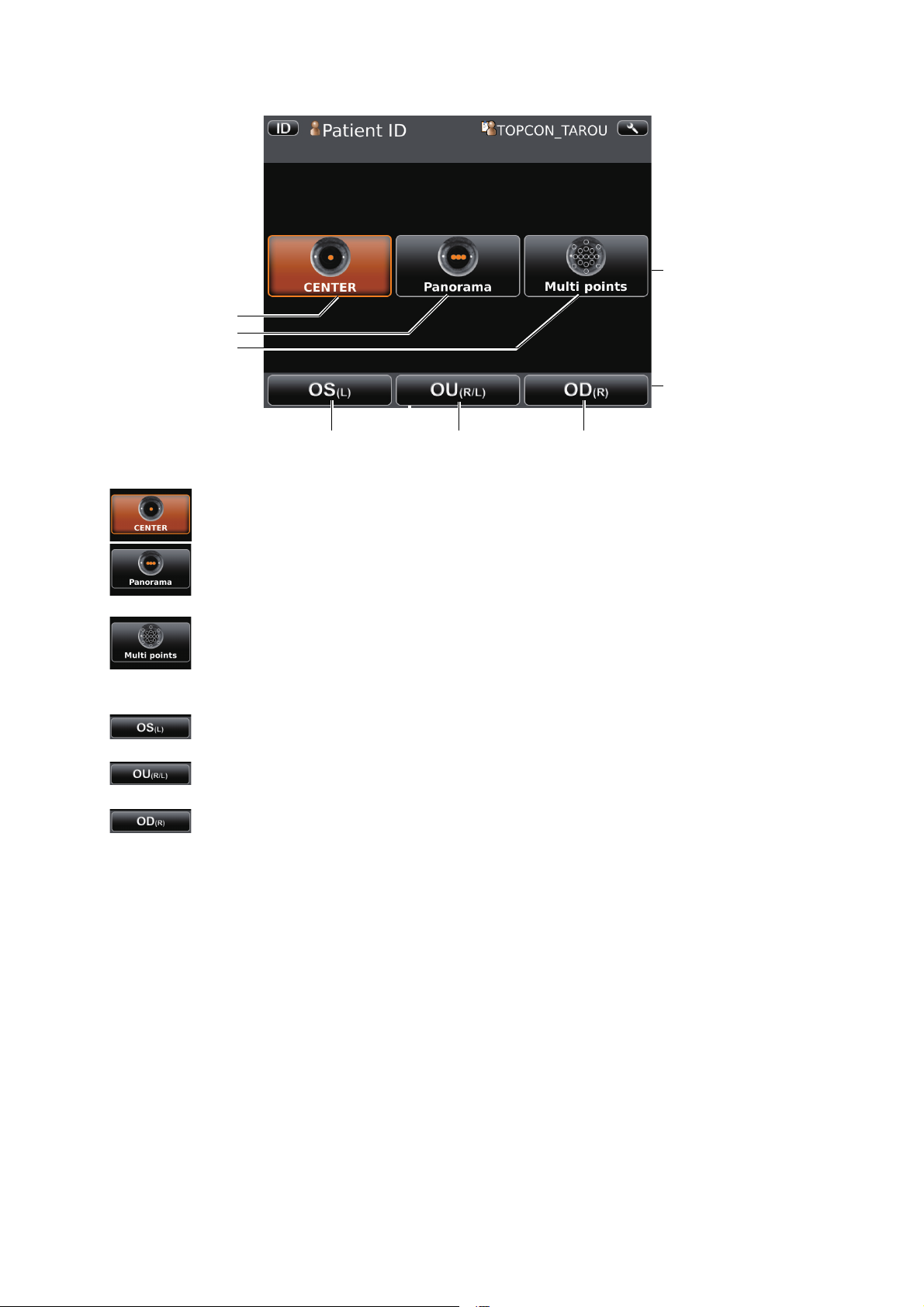
PHOTOGRAPHY SETTING SCREEN
OD(R) button
CENTER button
Panorama button
Multi points button
OU(R/L) button OS(L) button
Photography point
setting button
Button to select patient's
eye
CENTER button ..............................Centering photography is set.
Panorama button.............................Panorama photography that is to photograph 3 points around
the center is set.
Multi points button...........................Multi points photography that is to photograph specified cir-
cumference position is set.
OD(R) button...................................Photographs right eye only in the selected photography
point. If selection is complete, moves to capture screen.
OU(R/L) button................................Photographs two eyes (R/L) in the selected photography
point. If selection is complete, moves to capture screen.
OS(L) button....................................Photographs left eye only in the selected photography point.
If selection is complete, moves to capture screen.
• When Multi points button is selected, selecting one of OD(R) button, OU(R/L) button or
OS(L) button moves to photographing position selecting screen.
COMPONENTS
17
Page 20
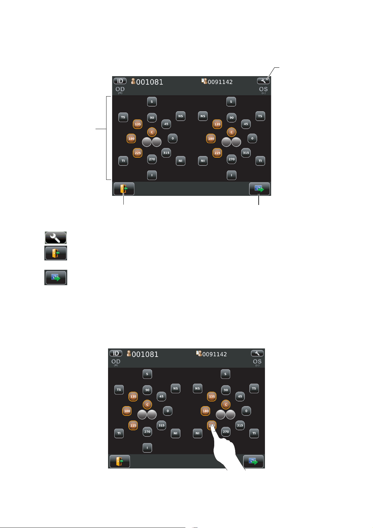
PHOTOGRAPHING POSITION (SHOWING POSITION OF FFIXATION TARGET) SELECTING SCREEN
Return button
Selecting position display
Next button
Settings button
R L R L
When Multi point button is selected in photography point, photographing position selecting screen is
shown. Photographing position is determined here.
R L R L
Selecting position display....................................The position to be photographed is selected.
Settings button ......................................Displays Setup screen.
Return button ........................................What has been entered is abandoned returns to patient
screen.
Next button ............................................The position selected is determined, moves to capture
screen. (If no position is selected, the next button is not displayed.)
• Operation on photographing position selecting screen.
Tap the button for the position to be photographed. Selected position is colored in orange.
• The fixation target is lighted on diagonal location for selecting the desired position.
18
COMPONENTS
Page 21
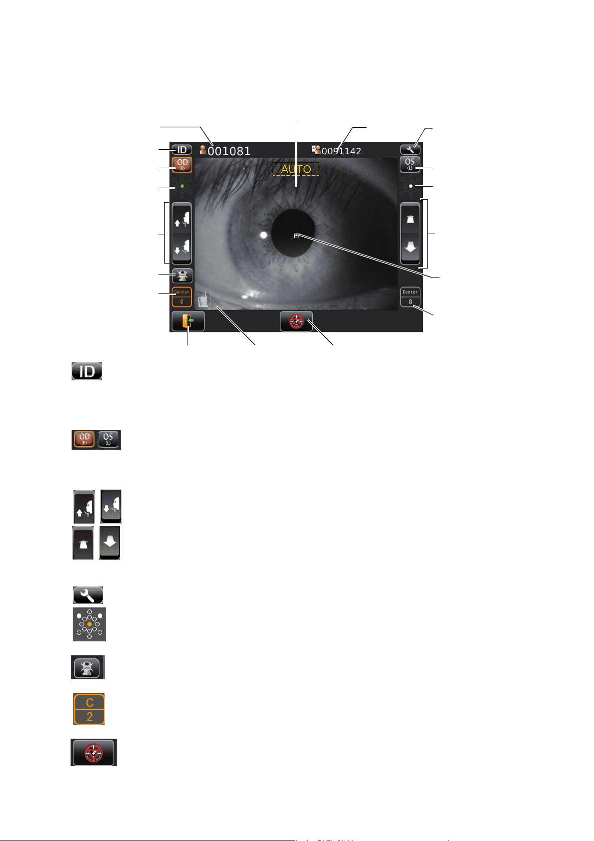
CAPUTER SCREEN
01
01
Please touch pupil
on the screen.
Ple ase touch p upil
on the screen.
Please touch pupil
on the screen.
Settings button
Up/down button for chinrest
OD button
OS button
Display
Forward/backward button
for photographing head
ID button
UNDER PHOTOGRAPHING
Device ID number
Photographing position display
(Right)
Photographing position/
number of photography
display (Right)
Photographing position display
(Left)
Operator ID
Patient No./Patient ID
Alignment mark
Return button
Photographing position/
number of photography
display (Left)
Emergency stop button
End button
Please touch pupil
on the screen.
The image to be observed is displayed operating the instrument to tell the state of setting or the
result of photography.
ID button...............................................Input the patient ID (up to 13 characters) and operator ID (up
OD button/OS button......................Select the right eye or left eye. The main body moves to
Up/down button for chinrest ............Moves the chinrest up/down.
Forward/backward button for photographing head.....Moves the photographing head closer to/
Settings button.......................................Displays the Settings screen.
Photographing position display .............The position selected is colored in orange. The position on
to 13 characters). However, if no patient ID is input, the
patient No. is allocated automatically.
Operator ID is not always shown according to the settings.
(See page 63 regarding on the settings)
selected direction by tapping this button. Selected eye is colored in orange. (OD: Right eye OS: Left eye) R/L display can
be reversed depending on the control panel position.
away from the patient's eye. Forward/backward movement
can be reversed depending on the control panel position.
which photography is complete is shown by white circle.
End button ............................................Move the chinrest and photographing head to the last posi-
tion.
Photographing position/number of photography display.....Displays contemporary Photographing
position selected and number of photographing.
Emergency stop button .....................Appears only when automatic operation is carried out. The
operation stops immediately.
COMPONENTS
19
Page 22
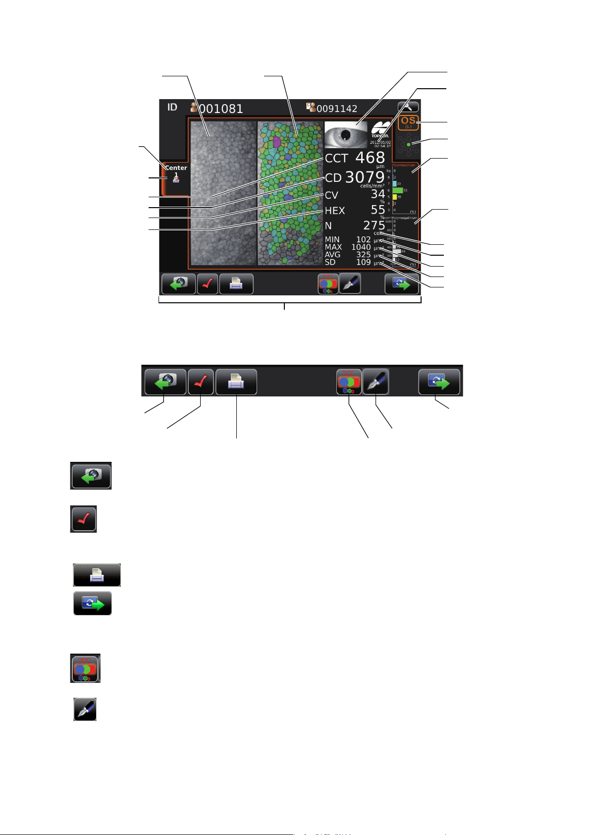
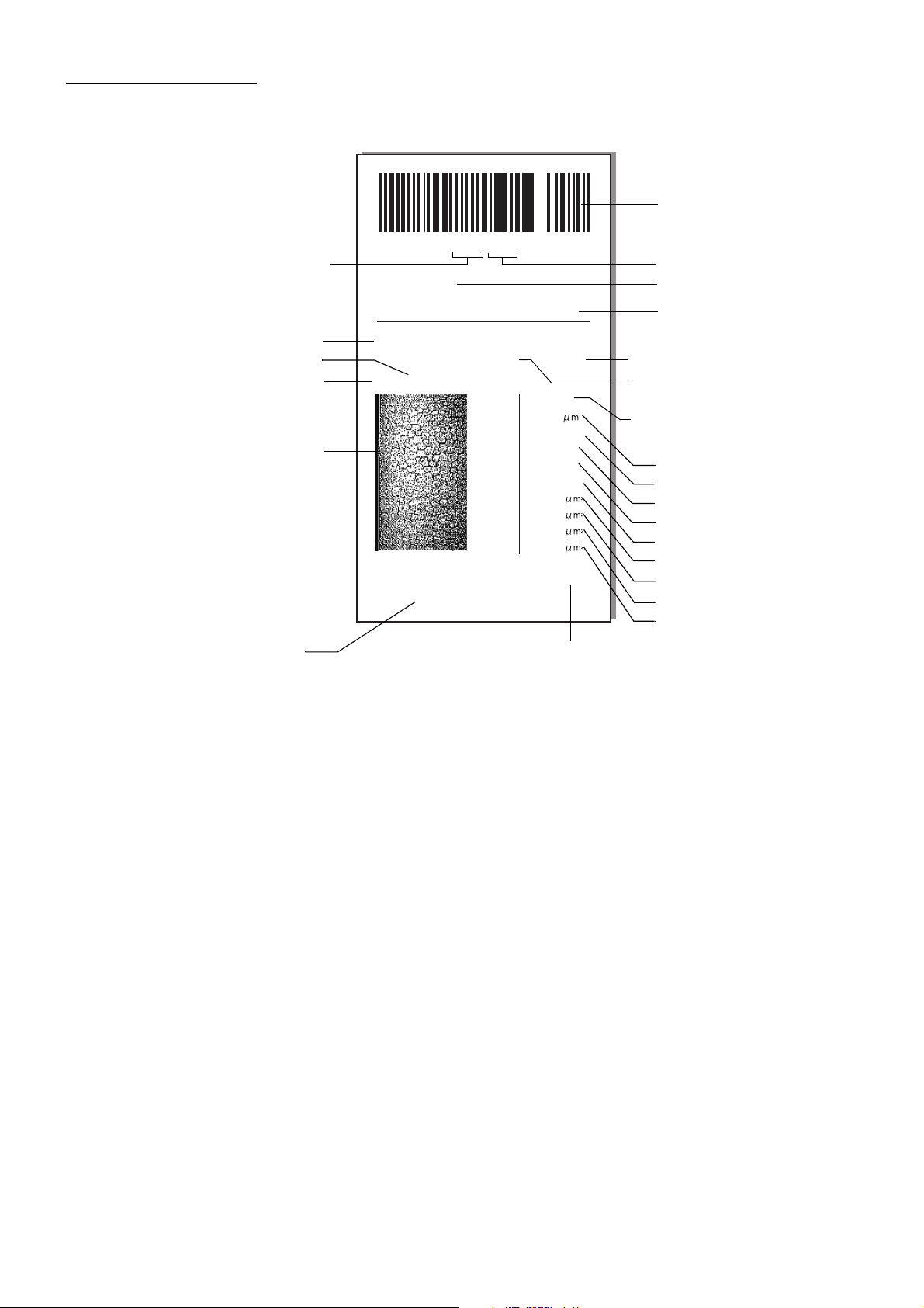
PHOTOGRAPHING RESULT SCREEN
Corneal endothelium image
(basis image)
Analyzing image
Print/Output reservation mark
Corneal thickness
Cell density
Coefficient of variation
Frequency of hexagon cells
Anterior image
Date of photographing
Square-shaped distribution
graph
Area distribution graph
Number of cell analyzed
Minimum cell area
Maximum cell area
Average cell area
Standard deviation of cell
area
Function button
Photographing position tab
OD button/OS button
Photographing point display
Rephotographing button
Print/output reservation button
Overlay button
Print/output button
Manual editing button
Next button
FUNCTION BUTTON
20
COMPONENTS
Rephotographing button ....................Photographing the same position.(The screen changes for
Photographing.)
Print/output reservation button .................This is shown only when more than 2 times photographed on
the same position.
Data contemporarily displayed is set to print/output.
Print/output button.........................Printing/output carried out according to the settings.
Next button........................................If there are more than 2 positions to photograph, next button
is displayed instead of Print/output button until photography
for the last position is complete. Tapping next button return to
capture screen to photograph the next position.
Overlay button........................................Classifies the image to analyze in color according to the
number of cell's angle or cell area.
Manual editing button.............................Moves to the screen for manual editing.
Page 23
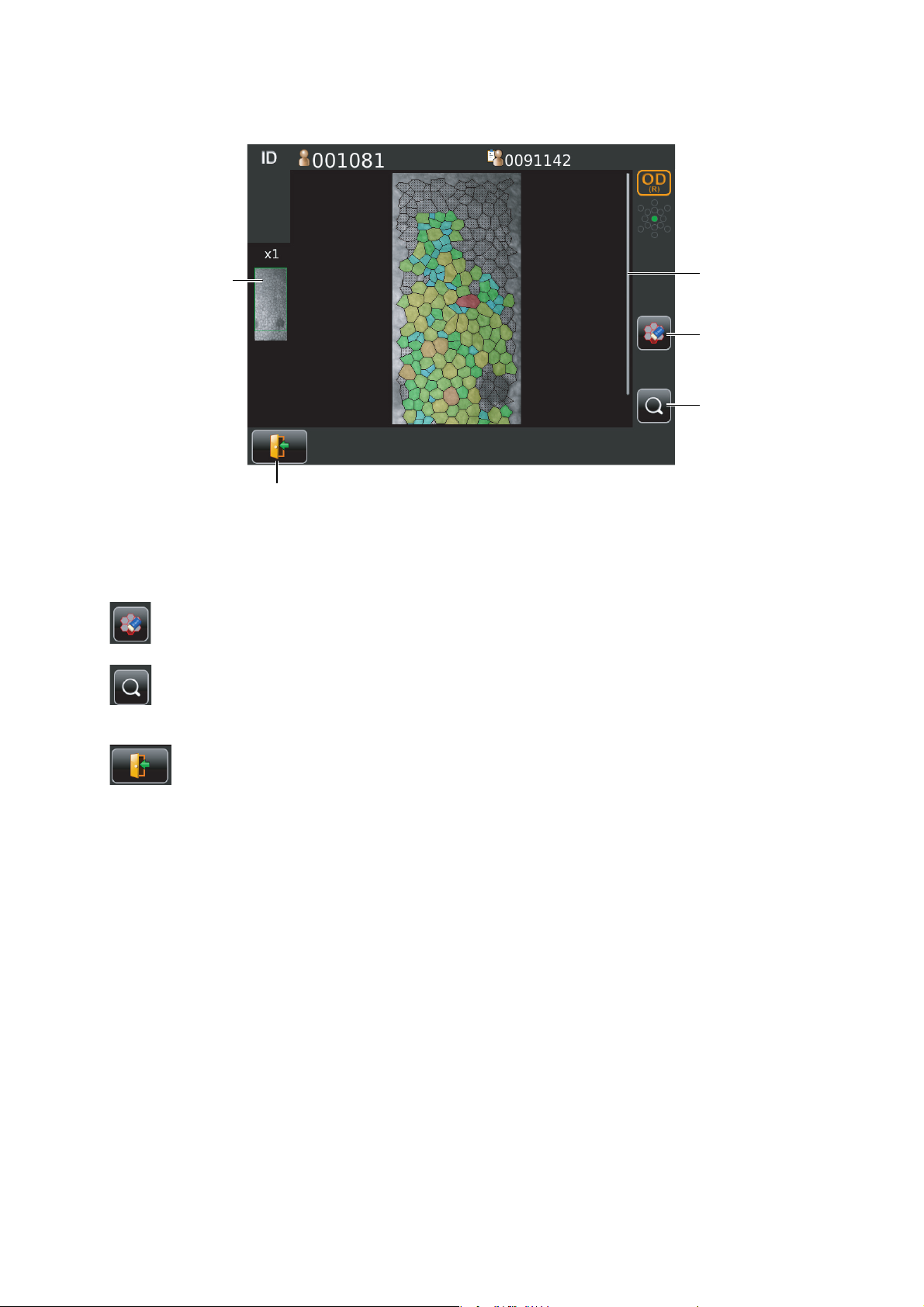
MANUAL EDITING SCREEN
Scroll bar
Thumb nail display
Excluding button
Return button
Zoom button
Screen for editing the result of automatic cell analysis.
Thumb nail display ..............................................When the image is enlarged the enlarged area is shown. The
area is flamed in green.
Scroll bar.............................................................Uses to show the hidden list by dragging up and down.
Excluding button ......................................Exclude the cell specified form analysis while remains
boundary line of cell.
Zoom button ............................................Enlargement/reduction of image is done.
When enlarged, you can move the area to be displayed by
dragging corneal endothelium image.
Return button......................................What is edited is canceled returning to the screen for analyz-
ing result image.
21
COMPONENTS
Page 24
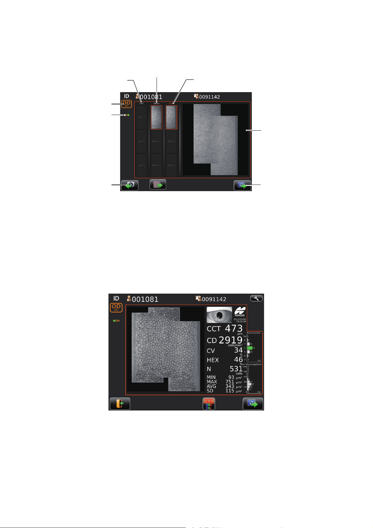
THE CHECKING SCREEN IN THE MIDDLE OF PANORAMA PHOTOGRAPHY
Rephotographing button
Next button
Photographing result
Left side Right side
Center
Photographing point display
OD button/OS button
This screen appears when panorama photography is carried out, where 3 images are combined and
photographing result of each position is checked.
RESULT SCREEN FOR PANORAMA PHOTOGRAPHY
Result screen after photographing 3 images in Panorama photography.
Button layout is same as that of normal photography result screen.
22
COMPONENTS
Page 25

SETUP SCREEN
23
COMPONENTS
Page 26

LIST OF PRINTING ITEMS SCREEN
Patient ID
TOPCON_TAROU
When more than 2 positions is photographed list of printing items is shown during print/output is carried.
After print/output is complete, the screen returns to patient screen automatically waiting next patient.
If the reliability is low, the character is displayed in yellow.
24
COMPONENTS
Page 27
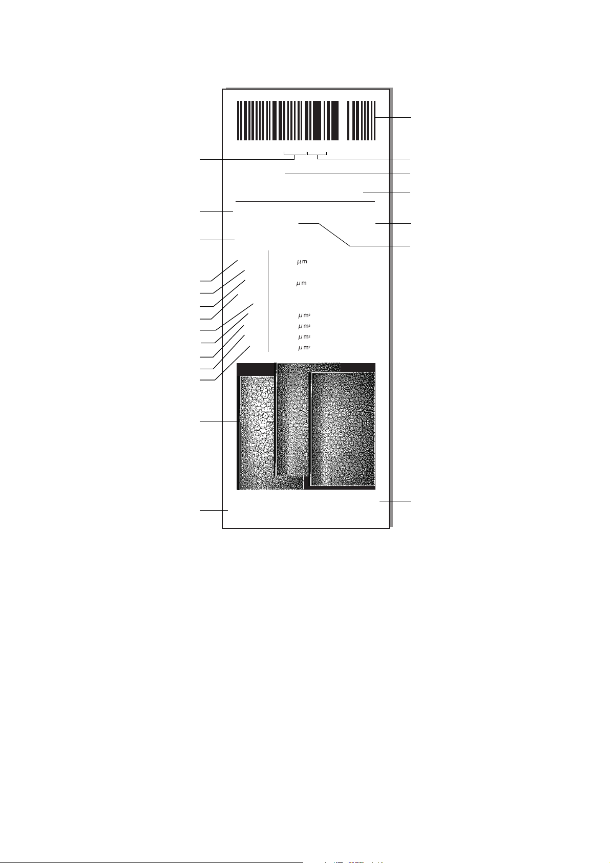
PRINTER OUTPUT
Barcode
Patient No.
Patient No.
(Patient ID when patient ID is input)
Device ID number
Operator ID
Cell density
Name entry column
Device ID number
Patient's eye
Measurement date
Photographing position
Number of cell analyzed
Minimum cell area
Maximum cell area
Average cell area
Standard deviation of cell area
Corneal endothelium image
Frequency of hexagon cells
Coefficient of variation
Corneal thickness
Input message
TOPCON logo mark
Low reliability mark
PRINTOUT OF SINGLE EYE PHOTOGRAPHED
OID:0123456
NAME
-SP01 0017-
2012_12_18
NO: 001081
OS(L)*
TOKO HOSPITAL
AM 11:00:53
POS Center
CD
556
1490
CCT
CV
HEX
179
N
MIN
MAX 583
AVG 303
SD 95
TOPCON
31
49
107
cells
/mm
%
%
cells
01
2
• As for the patient No., the result of the printing will differ depending on whether the patient
ID is inputted or not inputted.
Input : Patient ID is printed.
Not input : Patient No. (starts from 0001, automatically added +1 upon completion of
• If the reliability is low, low reliability mark(*) is outputted.
measurement) is printed.
25
COMPONENTS
Page 28
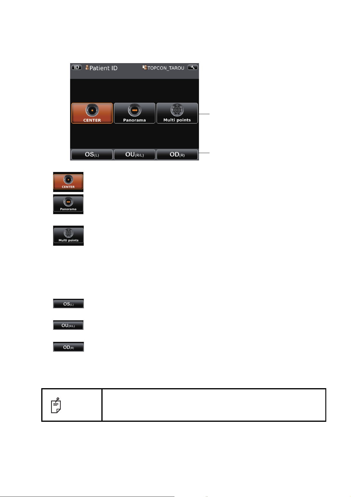
PRINTOUT OF PANORAMA PHOTOGRAPHED
Barcode
Patient No.
Patient No.
(Patient ID when patient ID is input)
Device ID number
Operator ID
Cell density
Name entry column
Patient's eye
Measurement date
Number of cell analyzed
Minimum cell area
Maximum cell area
Average cell area
Standard deviation of cell area
Corneal endothelium image
Frequency of hexagon cells
Coefficient of variation
Corneal thickness
Input message
TOPCON logo mark
Device ID number
-SP01 0017-
OID:0123456
NAME
2012_12_18 AM 11:00:53
NO: 001081
OD(R)
01
CCT
HEX
TOKO HOSPITAL
556
1490
CD
CV
31
49
179
N
MIN 107
MAX 583
AVG 303
SD 95
cells
/mm
%
cells
2
TOPCON
26
COMPONENTS
Page 29

STANDARD ACCESSORIES
S
PEC
U
LA
R
MICRO
SCO
PE
S
PECULA
R
MICROSCOPE
U
SER
MA
N
U
AL
S
PECULA
R
MICRO
S
C
O
PE
SP-1P
The following are standard accessories. Make sure that all these items are included (quantity).
User manual, Instruction manual,
Power cable (1)
Unpacking and Assembling (1 each)
Dust cover (1) Printer paper (2)
Monitor cleaner (1) Chinrest tissue (1)
Chinrest tissue pin (2)
Stylus pen (1)
27
COMPONENTS
Page 30

PREPARATIONS
External I/O terminal cover
Holding positions Holding the instrument
INSTALLATION
• When moving the instrument, two people should lift from the bot-
CAUTION
• To prevent damage and injuries, do not install the instrument on
• When setting an instrument on an instrument table, pay attention
• The instrument should also be placed away from strong light like
1 Use the base stopper to fix the main body.
Firmly hold the instrument at the position shown below and place it on the automatic instrument
table. For the adjustable instrument table, see "OPTIONAL ACCESSORIES" on page 77.
tom of the device.
One person lifting the device may cause harm to his back or
injury by falling parts. Also, holding areas other than the bottom
and holding the External I/O terminal cover may cause injury, as
well as damage to the instrument.
an uneven, unsteady or sloped surface.
not to injury the patient's fingers between the instrument and the
table.
direct sunlight. Auto alignment may not function properly.
2 After installation, turn the base stopper down. The main body can be moved.
CONNECTING POWER CABLE
Be sure to connect the power plug to an AC 3-pin receptacle
WARNING
CAUTION
1 Make sure the POWER switch of the instrument is OFF.
equipped with grounding. Connection with receptacle without
grounding may cause fire and electric shock in case of shortcircuiting.
To avoid electric shocks, do not handle the power plug with wet
fingers.
2 Tilt the body slowly so that the POWER switch is on top and the power inlet at the bottom can be
seen.
28
PREPARATIONS
Page 31

3 Connect the power cable to the Power inlet.
External I/O terminal cover
LAN I/O terminal
USB I/O terminal
4 Insert the power cable plug into the commercial power
(the 3-pin AC grounding receptacle.)
CONNECTING EXTERNAL I/O TERMINALS
CAUTION
When connecting this product with a commercial personal computer, use
NOTE
DATA OUTPUT
This product can be connected to a personal computer (PC) and other external devices via LAN.
one conforming to IEC60950-1.
To avoid electric shock, do not touch the external connection
terminal and the patient at the same time.
1 Remove the External I/O terminal cover by pulling up as follows.
2 Connect the connection cable to the I/O terminal of the instrument.
29
PREPARATIONS
Page 32

3 Connect the other end of the connection cable to the PC, etc.
4 Replace the External I/O terminal cover.
IMAGEnet
1 Connect the connection cord to the LAN I/O terminal of the instrument.
2 Connect the other end of the connection cord to the IMAGEnet system.
• The connection cord for IMAGEnet is an IMAGEnet optional accessory.
Prepare this cord prior to connection. For details on the IMAGEnet system,
contact your dealer (on the back cover).
NOTE
DATA INPUT
• Do not insert or remove the LAN cable while the power of the instrument is
ON.
• Sometimes the connection is not done properly because of the characteristics of the hardware. Use the LAN cable specified by TOPCON.
This product can be connected to a bar-code reader and other external devices via USB.
1 Connect the connection cable to the USB I/O terminal of the instrument.
2 Connect the other end of the connection cable to the external device.
NOTE
• For questions about connections, contact your TOPCON dealer.
• When you use a hub, use the USB hub with power supply.
30
PREPARATIONS
Page 33

PRINTER PAPER SETTING
Printer cover
Printer cover open switch
CAUTION
• To avoid failure or potential injury, do not open the printer cover
while the printer is in operation.
• To avoid potential injury in case of malfunction, including a paper
jam, be sure to shut off the power before attempting to repair it.
• To avoid potential injury, do not touch the printer body including
metal parts or the paper cutter, while the printer is in operation or
when replacing the printer paper.
NOTE
If you insert the printer paper backwards, printing will not start.
1 Press the printer cover open switch to open the printer cover.
2 Open the printer cover to the limit.
31
PREPARATIONS
Page 34

3 Insert the printer paper in the direction shown below and pull out the paper end to your side by 7
Roll direction
to 8cm.
4 Bring the paper into the center, then close the printer cover.
NOTE
• If the printer cover is closed when the power is ON, the paper cut operation is carried out automatically.
• In case the printer cover is not firmly closed, printing will not start.
• A 58mm wide paper roll is recommended. For the printer paper, see
"ORDERING CONSUMABLE ITEMS" on page 78.
Other paper rolls may cause abnormal printing noise or unclear print.
32
PREPARATIONS
Page 35

RECOVERY FROM POWER SAVE STATUS
(L)
(L)
()
This instrument adopts the power save system for saving electric power. When the machine is not
operated for a set time, the control panel becomes a screensaver.
1 Tap the control panel or operate the control lever.
In a few seconds, the measurement screen is displayed and photography is enabled.
The time to start the power save status can be changed in the initial setting
NOTE
ADJUSTING THE CONTROL PANEL POSITION
The control panel may be positioned by swinging and tilting the monitor to your desired position.
Touching the control panel controls operations including chinrest movements, alignment and photography.
"Auto power save" (see page 59).
NOTE
• The layout of OD/OS is reversed according to the position of the control
panel.
• The moving direction by tapping is changed according to the position of
the control panel.
• The instrument moves in the direction which continued pressing on a control panel at any control panel position.
(L)
33
PREPARATIONS
Page 36

BASIC OPERATIONS
Preparation of patient
(Positioning of patient's eye)
Set patient ID
Select photography point and patient's eye
PREPARATION BEFORE
PHOTOGRAPHING
(page 35 to 41)
Enter patient ID
Centering
photography
Panorama
photography
Multi point
photography
Print out (Data output)
Operation after use
Photographing
Select desired fixation target
PHOTOGRAPHY AND
ANALYSIS RESULT DISPLAY
(page 39 to 45)
Analyzing
(page 44)
(page 45)
Insert the power cable plug into the commercial power
When setting patient ID,
when selecting photography point
and patient's eye
Checking of the image
In the Panorama photography
In the Multi points photography
: Sequence course
: Free style course
: Common to
sequence and
free style course
Turn the power on
OPERATION FLOW CHART
Two different operation flows are available sequence course and free style course. Before shipment, default setting is sequence course.
• Sequence course .................. Setting Patient ID, photography point and patient's eye is
required before photographing. (In current chapter)
• Free style course...................Photographing is allowed when turning on. (See P.46)
34
BASIC OPERATIONS
Page 37

PREPARATION BEFORE PHOTOGRAPHING (SEQUENCE COURSE)
POWER
Patient screen for DICOM work list Patient screen for ID input
Next button
Patient ID input change button
Next button
Input button
Next button
• Do not put the patient's chin on the chinrest until the power is on.
NOTE
• If room temperature becomes low at 10°C or less in the winter, after turned
the power switch on, warming up is necessary before use. Image quality
may be influenced for low temperature.
TURN THE POWER ON. SET PATIENT ID.
1 Insert the power cable plug into the commercial power (the 3-pin AC grounding receptacle.)
For the details of connection, refer to "CONNECTING POWER CABLE" on page 28.
2 Press on the switch.
• Make sure that the title screen is displayed and then the patient screen is displayed. The
patient screen is shown for a while.
• When selecting the patient form DICOM work list, select the patient on the list, tap the
.
To enter the ID, enter patient ID by use of , finally tap the .
(Refer to page 15 regarding how to input ID.)
Photography setting screen is shown.
35
BASIC OPERATIONS
Page 38
SELECT PHOTOGRAPHY POINT AND PATIENT'S EYE
Photography point setting button
Button to select patient's eye
1 Tap the photography point setting button.
CENTER button .........Centering photography is carried out.
Panorama button........Panorama photography that is to photograph 3 points around
the center is set.
Multi points button ...... Multi points photography that is to photograph specified cir-
cumference position is set.
• If the Multi points button is selected, select the photographing position on the Photographing position selecting screen. For the details see the 18 pages.
2 Tap the button to select patient's eye.
OD(R) button......Photographs right eye only in the selected photography point.
If selection is complete, moves to capture screen.
OU(R/L) button...Photographs two eyes (R/L) in the selected photography point.
If selection is complete, moves to capture screen.
OS(L) button ......Photographs left eye only in the selected photography point.
If selection is complete, moves to capture screen.
3 Move to the capture screen.
NOTE
36
BASIC OPERATIONS
In the sequence course, changing the photographing points is impossible
during photographing. If the changing is necessary, you have to photograph
in free style course.
Page 39

PREPARATION OF PATIENT
Eye height mark of
photographing window
Eye height mark
CAUTION
• Adjust the height of the adjustable instrument table so that the patient can
sit on the chair comfortably. Otherwise, correct measurement values may
not be obtained.
• When operating the instrument (for measurement and control panel oper-
NOTE
ation), be careful that the instrument does not touch the patient's lip or
nose. If touched, clean the instrument following "CLEANING THE FOREHEAD REST AND CHIN REST" on page 83.
• If no patient ID is registered, a "patient No." is assigned and displayed
automatically in order of examination.
1 Check the capture screen.
• To avoid electric shock, do not touch the external connection terminal and the patient at the same time.
• To avoid injury, do not insert fingers under the chinrest.
To avoid injury when moving the chinrest down, be careful not to
catch the patient's finger. Tell this to the patient, too.
• To avoid injury when operating the machine (for measurement
and control panel operation), be careful about the cover not to
catch fingers of the patient. Tell this to the patient, too.
2 Make sure that Photographing window is at the height of the eye height mark. Move the photo-
graphing head until photographing window is at the height of the eye height mark, if photographing window is above the eye height mark press the lower side of the control panel display, or if it
is beneath the eye height mark press the upper side of the control panel display.
3 Have the patient sit in front of the instrument.
4 Adjust the adjustable instrument table or the chair height for the patient to put his/her chin on the
chinrest comfortably.
5 Place the patient's chin on the chinrest and check that his/her forehead is touching to the fore-
head rest.
37
BASIC OPERATIONS
Page 40

6 Press the to adjust the chinrest height until the eye height mark of the chin-
UP/DOWN button
Up/Down button for chinrest
Eye height mark
rest reaches the same height as the patient's eye. At this moment, confirm that the height mark
of the photographing window is at the height of the patient's visual line.
38
BASIC OPERATIONS
Page 41

PHOTOGRAPHY AND ANALYSIS RESULT DISPLAY
D
TOPCON
1
D
PatientID
TOPCON
TOPCONTAROU
OS
OD
(R)
(L)
Position of
fixation target
• Photographing may not be possible, in case the eyelid and the eyelashes
cover the pupil.
If this occurs, the operator should tell the patient to open their eyes as
wide as possible, or lift the eyelid to allow for measurement.
• Photographing may not be possible due to frequent blinks or existing
abnormalities in the corneal surface caused corneal disease etc.
NOTE
ALIGNMENT AND PHOTOGRAPHY
Alignment can be operated from the control panel.
In this case, select manual mode.
• When operating the instrument (for measurement and control panel operation), be careful that the instrument does not touch the patient's lip or nose.
If touched, clean the instrument following "CLEANING THE FOREHEAD
REST AND CHIN REST" on page 83.
• If the patient is wearing make up on the eyelid or around the eyelid using
glitter, the auto alignment may not function properly. In this case, select
manual mode.
1 Have the patient look at the fixation target (blinking in green.) in the photographing window. If
blinking in green stops tell the patient suppress so to suppress eye blinking approx.3 seconds.
(Photographing is carried out at this time.)
2 When the pupil is displayed, tap the area around the pupil. The photographing head moves to
display the pupil image and alignment dot on the center of the screen.
TOPCONTAROU
PatientI
TAROU
OD
(R)
PatientID
PatientI
1
TAROU
OS
(L)
3 Alignment starts automatically, and photographing is performed.
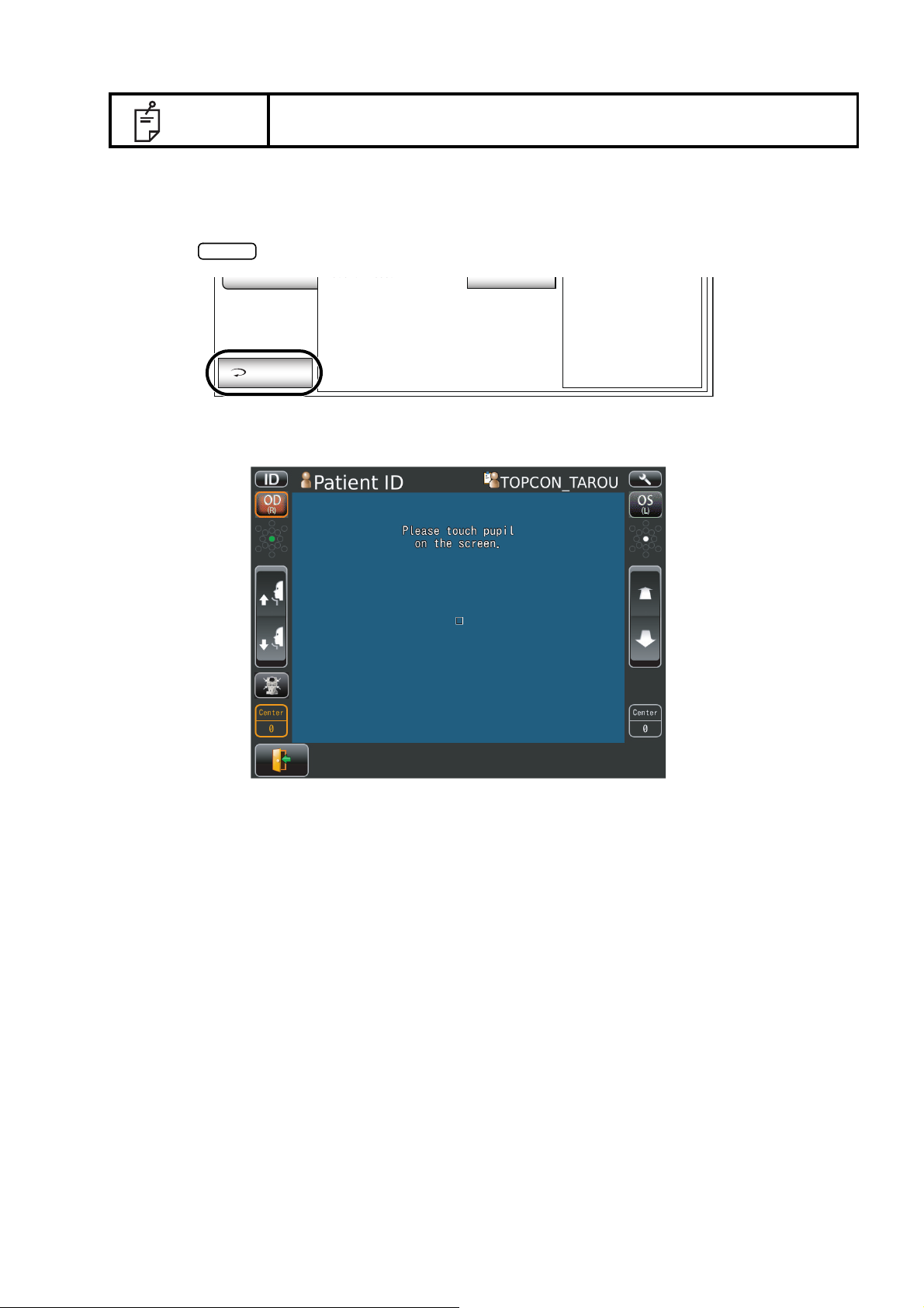
• When "Please touch pupil on the screen." is displayed, please confirm if
the patient's eye fits normal conditions for measuring. Then tap the pupil
on the control panel again.
NOTE
• When the alignment status has continued for more than 30 seconds, the
operation stops telling "Please touch pupil on the screen". Tap the photographing Head Forward/Backward button to focus. Then tap the pupil on
the control panel again.
39
BASIC OPERATIONS
Page 42
NOTE
TOPCON
Limit mark
U
TOOFAR
U
TOOCLOSE
Limit of movement in the
forward direction
Limit of movement in the
backward direction
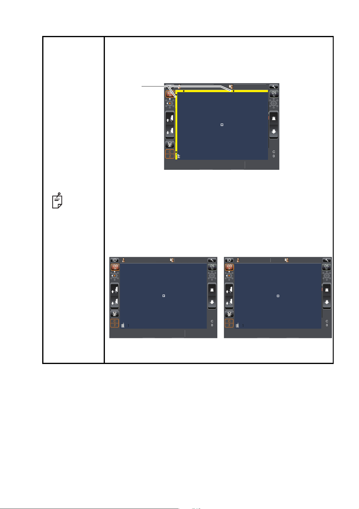
• When the photographing head has reached the limit of movement (vertical/lateral directions), a yellow-colored limit mark appears on the control
panel’s top, showing it is the movement limit in that direction. Tap the display, move the photographing head to the position where aligning is possible.
TOPCONTAROU
TAROU
OS
(L)
OD
PatientID
PatientID
(R)
1
1
• The limit display is shown also when the patient's face position is incorrect. Check that the patient's face is in proper position, then move the
photographing head.
• When the photographing head is at the limit of movement in the forward
direction, "TOO CLOSE" is displayed, and when it is at the limit of movement in the backward direction, "TOO FAR" is displayed. Using the photographing Head Forward / Backward button, move the photographing head
to the position where aligning is possible.
TOPCONTAROU
OD
PatientID
PatientID
(R)
TOOFAR
1
TOPCONTARO
OS
PatientID
PatientID
OD
(L)
(R)
1
• For manual alignment , refer to page 42 "IN MANUAL ALIGNMENT".
TOOCLOSE
TOPCONTAROU
TOPCONTARO
OS
(L)
40
BASIC OPERATIONS
Page 43

Results of Photography and analysis.
Corneal endothelium image
(basis image)
Analyzing image
Print/Output reservation
mark
Corneal thickness
Cell density
Coefficient of variation
Frequency of hexagon cells
Anterior image
Date of photographing
Square-shaped
distribution graph
Area distribution graph
Number of cell analyzed
Minimum cell area
Maximum cell area
Average cell area
Standard deviation of cell
area
Photographing position display
OD button/OS button
Photographing position tab
Rephotographing button
Rephotographing
button
• If photography is required again, return to the capture screen by tapping
. Then you can photograph again.
• The analyzing image is classified in color according to number of angle of cell and area of
cell by tapping overlay button .
The analyzing image is classified in color according to number of angle of cell
The analyzing image is classified in color according to area of cell
• The cell that is no colored and displayed with black boundary line and dot is excluded from
analyzed value calculation.
BASIC OPERATIONS
41
Page 44

4 Under "Panorama photography" is set, the procedure is follows; "photographing" - "check the
High speed
Low speed
photographing result" - "photographing" - "check the photographing result", then repeat same
procedure. Photographing is performed at three points as center, ear side, and nose side.
Under "Multi points photography" is set, the procedure is "photographing" and "check the photographing result", and repeat same procedure according to selected points.
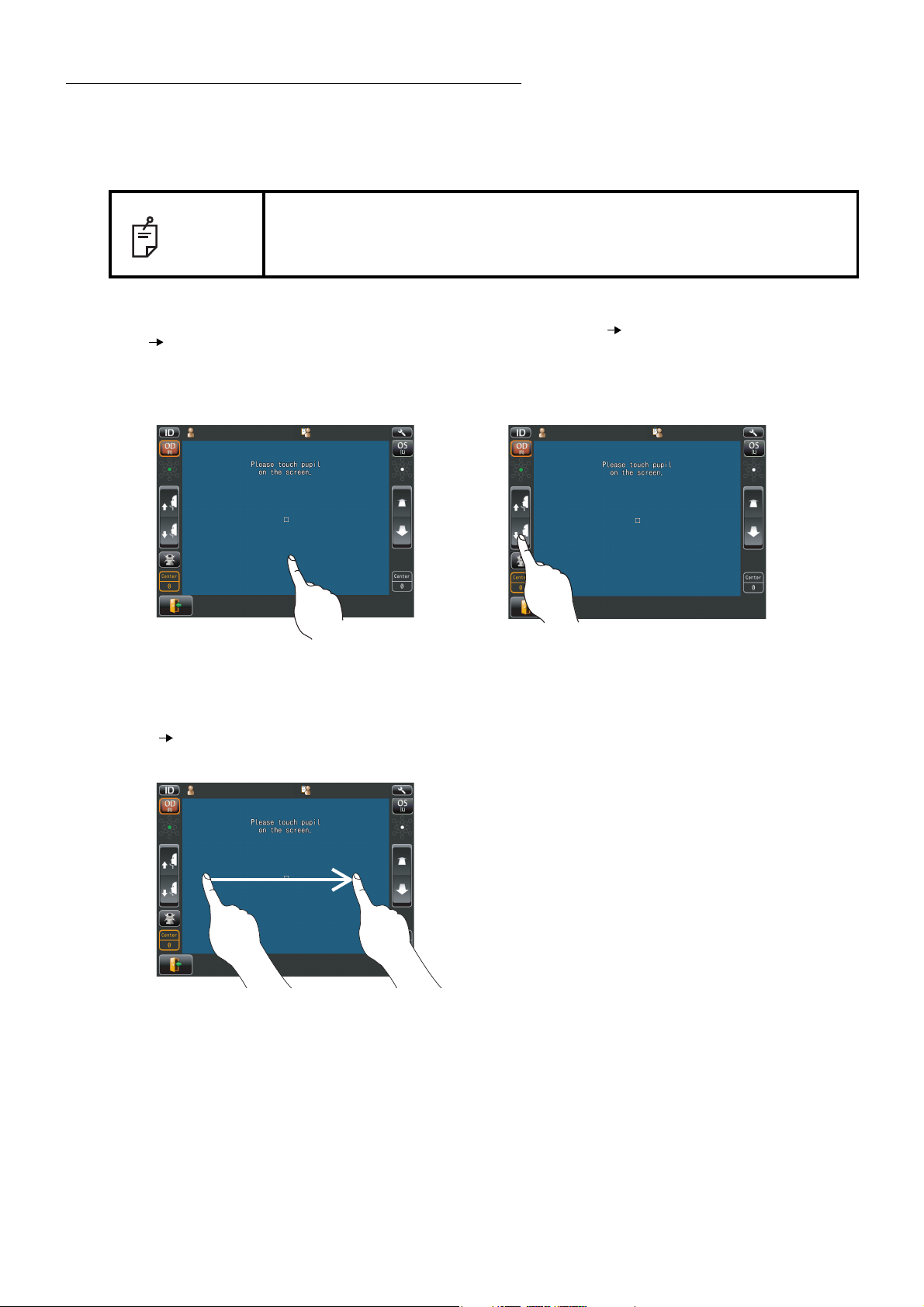
IN MANUAL ALIGNMENT
To keep pressing on the screen, the instrument moves to the direction from center of screen to the pressed point.
It is possible to change the direction by dragging on the screen,
too. The instrument does not move even if you press around center of screen without the bar.
NOTE
Moving speed is changed according to the distance between center of screen and pressed point.
Moving speed is higher than away from a screen center.
42
BASIC OPERATIONS
Page 45

NOTE
During vertical/lateral directions movement, the movement mode is
changed to back /forth by tapping (at one second) the center of screen.
Under Back/forth movement mode, it is possible to move like the
arrow of the screen.
43
BASIC OPERATIONS
Page 46

PRINT-OUT OF PHOTOGRAPHING DATA
Print/Output button
Print/Output button
Print/Output button
Print/Output button
• To avoid a paper jam in the printer, do not feed the paper if it is partly cut
or wrinkled.
• To avoid discoloring of the printer paper (particularly the recording area)
during storage, use a polypropylene bag and not one containing plasti-
NOTE
cizer (PVC, etc.).
• To avoid discoloring of the printer paper (particularly the recording area)
after pasting, use water-soluble glue and not one containing solvent.
• Since the printer paper is thermosensitive, it is not suitable for keeping
records for a long period. If necessary, prepare copies separately.
This instrument can print out photographing data by internal printer.
1 Make sure that is displayed on Photographing result screen.
• If Panorama photography, Multi points photography and Binocular photography is selected,
does not appear until all specified photographing is completed.
2 List of printing items screen is displayed.
3 Tap the on the List of printing
items screen.
Photographing values on the List of printing
items screen are printed out.
Patient ID
ޛ4ޜ
OO*I#&,OO*I#&,
'44
#8)
ޛ4ޜ
J2C#&,
'44
'44
'44
#8)
2#%1#
4 OO
. OO
#8)
/GUUCIG
612%1
0
0Q-GPL[CA
50
6101#
'44
ޛ
.ޜ
J2C#&,
1+&-GPL[CA
0#/'
AA#/
ޛ.ޜ
'44
'44
TOPCON_TAROU
%6
'44
DATA OUTPUT
If personal computer and external devices are connected with this instrument, outputting data and
printing out are simultaneously performed by tapping the .
44
BASIC OPERATIONS
NOTE
• When a red line is printed at the end of the printer paper, replace it with a
new one. For details about the replacement of printer paper, see
"PRINTER PAPER SETTING" on page 31. 58mm wide printer paper is
recommended. For the printer paper, see "ORDERING CONSUMABLE
ITEMS" on page 78.
• "CLOSE PRT COVER" is indicating that the printer cover is left opened,
ensure that the printer cover is completely closed.
Page 47

OPERATION OF AFTER USE
End button
POWER
1 Tap the on the control panel.
The message of "Turn off the unit?" is displayed.
2 Tap the "YES". Return the chinrest and photographing head to the last position.
The message of "Please don't turn the main switch off until the unit stops." is displayed on the
control panel.
The operation is complete, then the message of "The unit stops completely. Please turn the
main switch off." is displayed.
3 Turn the switch to off.
When external devices are connected to external I/O terminals, turn off the
NOTE
power of these devices too. (If power switch is provided.)
4 Unplug the power cable from Commercial power (the 3-pin AC inlet with grounding.
When the instrument is not used for a long period of time, unplug the power
NOTE
supply cable, and detach the cable connected to the external I/O terminal.
45
BASIC OPERATIONS
Page 48

OPTIONAL OPERATIONS
POWER switch
Photographing position selecting button
Photographing position
selecting button
Panorama
When a captured region button is tapped, you can
see the captured data in that region.
Note
Panorama
OS/OD (L/R) button
Panorama button
FREE STYLE COURSE PHOTOGRAPHY
In the free style course, it is possible to capture an eye as soon as the power turns on; selecting the
patient's ID, photography point or patient's eye is not required.
• To change to free style course form the sequence course the setup
screen is used.
• Regarding how to change, see P.55-59.
NOTE
• In free style course, it is possible to set photographing position as desired.
• As it is impossible to keep the result of desired position and panorama
photography simultaneously in free style course; print/output either result
then repeat the photographing procedure from the beginning.
1 Insert the power cable plug into the commercial power (the 3-pin AC grounding receptacle,)
press on the . Make sure that the title screen is displayed and then the capture
screen is displayed.
2 Tap the to change the position.
3 Photographing position selecting screen appears. Tap the desired position on the screen, and
change the L/R eye by OS/OD button if necessary. If Panorama photography is required, tap
the button. For the detail of Panorama photography, see P.48.
46
OPTIONAL OPERATIONS
Page 49

4 Start Preparation of patient (Refer to P.37 "PREPARATION OF PATIENT")
Print/Output buttonPrint/Output reservation button
Photographing position tab
Print/Output reservation
mark
Captured region display button
Captured region display button
Print/Output reservation button
Print/Output button
5 Carry out Photographing. (Refer to P.39 "ALIGNMENT AND PHOTOGRAPHY")
Results of Photography and analysis are displayed.
6 If photographing of the required position is complete, select the result for printing position.
Tap the , the chart of all captured region is displayed. If tapping
each button of region, each analysis result of region is displayed for checking.
7 Tap the while the specified image for printing displays on the
screen.
Print/output reservation mark appears on the photographing position tab, then the print reservation is complete.
8 Tap the to print the reservation result of photography.
47
OPTIONAL OPERATIONS
Page 50

PANORAMA PHOTOGRAPHY
Panorama
Panorama
Button to select
patient's eye
Ple ase tou ch pup il
on the scr een.
Current photographing
position
Photograph 3 points-center, ear side and nose side. Those images are combined automatically and
observation of large area can be performed.
• In the case of sequence course, preparation and photography are carried out as the following procedure.
• In the case of free style course, preparation and photography are carried out from following
procedure 4 after tapping the button in the Photographing position.
1 Set Patient ID. (Refer to page 35)
2 Tap the button.
3 Select the patient's eye by tapping the button to select patient's eye.
Then move to the screen for observation.
4 Please prepare to photograph for patient. (Refer to page 37)
5 Have the patient look at the fixation target (green) in the photographing window.
6 Tap the pupil on the screen.
The alignment is performed automatically and photographs.
• Changing the patient ID or patient name is impossible after tapping the screen.
7 Preview of result of photography is shown.
Until photographing next point, the patient has a break.
Please touch pupil
Please touch pupil
on the screen.
on the screen.
01
48
OPTIONAL OPERATIONS
Page 51

8 Check the result of photography. If photography is required again, tap the
Rephotographing
Next button
Result of photography
Rephotographing button
Center Right sideLeft side
Photographing point display
OD button/OS button
Next button
Rephotographing button
Result of photography
Next button
Result of photography
Analyze button
Analyze button
button.
9 Tap the to photograph next position.
The capture screen is shown. Photograph the same manner in Step4-7 (page 48).
The image is displayed in combined image with previous one.
Repeat checking the photographing image and photographing next position in the same manner
so that photographing is performed at 3points.
10 Tap the , "Do you want analyzed using the combined image?" is displayed.
If tapping "Combined image", the analyzing image is displayed in combined image.
The analyzing of using combined image is available after photographing 2 points.
49
OPTIONAL OPERATIONS
Page 52

11 Check the analyzing result and if required tap the to print/output the
Print/Output button
Analyzing screen of combined image
Print/Output button
Print/Output button
result.
12 The List of printing items screen is displayed, then tap the print/output button. The analyzing
result is printed.
13 The message of "Are you sure to start next measurement? Please select whether to input new
patient ID or not." is displayed.
• If "New ID" is selected, moves to work list or ID input screen.
• If "Same ID" is selected, the measurement is continued under same patient.
DISPLAYING THE PATIENT ID (PATIENT No.) OR OPERATOR ID
A patient ID or operator ID of up to 13 characters can be input and displayed on the control panel
and printout.
If no patient ID is registered, a "patient No." is assigned automatically in order of examination.
FOR DICOM WORK LIST
1 Select a specified patient from the list. If there is no patient in the list, please tap the list update
button to update information.
2 Tap the photography settings changeover button so that the selection is complete.
FOR ID INPUT
• In ID input method, patient ID changeover button can be used to change to work list
method.
1 Tap the keyboard on the display to enter the ID.
2 Tap the photography settings changeover button so that the selection is complete.
50
OPTIONAL OPERATIONS
• In work list method, patient ID change over button can be used to change to ID input
method.
• Keyboard layout can be changed qwerty/ten key by means of keyboard changeover button.
Page 53

CELL ANALYSIS IN EDITING MODE
Icon
Various data
Thumb nail display
Excluding button
Return button
Zoom button
Scroll bar
If the detailed mode setting is ON, editing button is shown. Use of a stylus pen is recommended to
edit.
1 Make sure that Photographing result screen is displayed.
2 Tap the manual editing button . Manual editing screen is displayed.
Thumb nail display ..............................................When the image is enlarged the enlarged area is shown. The
area is flamed in green.
Scroll bar.............................................................Uses to show the hidden list by dragging up and down.
Excluding button......................................Exclude the cell specified form analysis while remains
boundary line of cell.
Zoom button............................................Enlargement/reduction of image is done.
When enlarged, you can move the area to be displayed by
dragging corneal endothelium image.
Return button......................................Return to Analysis result screen. (The changes are dis-
carded.)
51
OPTIONAL OPERATIONS
Page 54

3 Tap the , then the message of "Are you sure to apply change?" is displayed.
Analyze button
Analyze button
If tapping "OK", the analyzing screen where the change was applied is displayed.
If tapping "Cancel", the analyzing screen where the change was discarded is displayed.
52
OPTIONAL OPERATIONS
Page 55

OUTPUT TO IMAGEnet SYSTEM
Print/Output button
Print/Output button
• Set LAN output to ON.
1 Check the connection of IMAGEnet system.
For connection, refer to "CONNECTING EXTERNAL I/O TERMINALS" on page 29.
2 Photographing is performed at all position.
3 Tap the on the screen to display the List of printing items
screen.
4 Tap the on the List of printing items screen.
The image is automatically captured into IMAGEnet system.
53
OPTIONAL OPERATIONS
Page 56

INPUT USING USB
PRINT OUT
This instrument can input ID numbers from a bar code reader, etc. via the USB.
1 Check the connection of USB IN.
For connection, refer to "CONNECTING EXTERNAL I/O TERMINALS" on page 29.
2 Input ID numbers from the external device.
The inputted ID numbers are displayed on the screen.
OUTPUT USING LAN
This instrument can output data to a PC, etc. via the LAN interface.
1 Connect the network cable to LAN OUT.
For connection, refer to "CONNECTING EXTERNAL I/O TERMINALS" on page 29.
2 Set up of LAN connection settings.
For details, refer to "NETWORK SETTINGS" on page 61.
3 Perform photograph. Tap the button of the control panel.
Output is completed.
NOTE
For explanation of messages during communication refer to the
"MESSAGE LIST" on page 64.
54
OPTIONAL OPERATIONS
Page 57

SETTING FUNCTIONS ON SETUP SCREEN
POWER
SETTINGS
Index
Back Page button Page display Next page button
Exit button
Descriptions Options
Current condition button
OPERATING THE SETUP SCREEN
Various functions can be set on the SETUP screen.
PREPARATONS FOR SETTING
1 Make sure that the power cable is connected.
For connection, refer to "CONNECTING POWER CABLE" on page 28.
2 Turn ON the switch.
3 Tap the button on the control panel.
The SETUP screen is displayed.
1/3
Initial
Settings
Internal
Printer
External
Printer
Network
Settings
Operator
Settings
Exit
Capture mode
Free style start
screen
Buzzer
Stand by mode
Patient IDreset
Sequence
Capture Screen
ON
Right
OFF
OFF
ON
SETTING FUNCTIONS ON SETUP SCREEN
55
Page 58

OUTLINE OF SETUP SCREEN OPERATIONS
INDEX
Initial
Settings
Internal
Printer
External
Printer
Network
Settings
Operator
Settings
Exit
1/3
Capture mode
Free style start
screen
Buzzer
Stand by mode
Patient IDreset
S
Cap
NEXT PAGE
BACK PAGE
Initial
Settings
Internal
Printer
External
Printer
1/3
Capture mode
Free style start
screen
Buzzer
C
CURRENT CONDITION
OPTIONS
Initial
Settings
Internal
Printer
External
Printer
Network
Settings
1/3
OFF
Capture mode
Free style start
screen
Buzzer
Stand by mode
Sequence
Capture Screen
ON
Right
ON
OPTIONS
Initial
Settings
Internal
Printer
External
Printer
Network
Settings
1/3
OFF
Capture mode
Free style start
screen
Buzzer
Stand by mode
Sequence
Capture Screen
ON
Right
ON
OPTIONS
1 Tap and select the subject of setting.
2 Operate the button or button, as necessary, and display the page
to confirm/change.
3 Tap the button of the item to be changed and find the button.
4 Tap the button and change the setting.
• Instead of the button, pull-down menu and ten-key would be displayed.
56
SETTING FUNCTIONS ON SETUP SCREEN
Page 59

PULL-DOWN MENU:
2/3
Initial
Settings
Internal
Printer
External
Printer
Network
Settings
Operator
Settings
Exit
64
58
60
62
64
66
68
70
72
74
Show device ID
number
Device ID number
Pupil distance
Auto power save
Chinrest height
Control panel
brightness
Language
OFF
01
64(mm)
OFF
English
Middle
Level 4
Pull-down menu
Enter
1/3
Initial
Settings
Internal
Printer
External
Printer
Network
Settings
Operator
Settings
Exit
0 㸬
1 2 3
4 5
6
7 8 9 BS
Enter
192.168.0.1
Use LAN
IP address setting
IP address
Subnet mask
Default gateway
Primary DNS server
Secondary DNS
server
ON
Fixed
address
0.0.0.0
-None-
-None-
-None-
-None-
Enter window
OK
Public Folder㧔32㧕
User㧔32㧕
Password㧔16㧕
1 7
ψ
23 4 56 890
φ
BS
z mx c v b n 㧚
q uw e r t y i o p
DEL
ajs d f g h k _ -
\
SPACE
CAPS
OK Cancel
Enter window
Tap the options button to show a pull-down menu.
Select a figure and value etc. to be changed in menu items.
TEN-KEY:
Tap ten-key on the screen and enter the figure. If there are several windows to enter, tap the window
to enter the figure by ten-key. Tap and fix the input value.
KEYBOARD:
Tap keyboard on the screen and enter characters. If there are several windows to enter, tap the
window to enter the figure by keyboard. Tap and fix the input value.
SETTING FUNCTIONS ON SETUP SCREEN
57
Page 60
NOTE
Exit
Operator
Settings
Exit
Patient IDreset
OFF
The set value is updated when an options button is tapped.
RETURNING TO THE MEASUREMENT SCREEN
1 Tap the button.
2 The capture screen is displayed.
58
SETTING FUNCTIONS ON SETUP SCREEN
Page 61

LIST OF SETUP ITEMS
Setup items are categorized into 6 large indexes.
"Initial Settings" .........................items related to the initial status after power on
"Internal Printer" ........................items related to output from the internal print
"External Printer".......................items related to output from the external print
"Network Settings".....................items related to output using the LAN
"Operator Settings"....................items related to Operator ID
INITIAL SETTINGS
Initial contains settings related to the initial status after power on, clearing all measurement values,
etc.
Descriptions Options Details Initial value
Capture mode
Free style start screen
Buzzer
Stand by mode
Patient IDreset
Show device ID number
Device ID number
Pupil distance
Auto power save
Chinrest height
Control panel brightness
(Setup of the brightness of
control panel)
Language
Date/Time Set by ten-key display. Sets year, month, day, time (24hrs), minute and second
Sequence Operation flow is set as sequence course.
Free style Operation flow is set as free style course.
Capture Screen Free style start screen is set to capture screen.
Patient Screen Free style start screen is set to patient screen.
ON Buzzer does not sound.
OFF Buzzer sounds.
Right Waiting at the initial position for right eye measurement.
Last Waiting at the last position of the measured eye.
ON Patient No. is reset upon power on.
OFF Patient No. is not reset upon power on.
ON Device ID is displayed.
OFF Device ID is not displayed.
Set by ten-key display.
Set by pull-down menu
1-99
58mm
60mm
62mm
64mm
66mm
68mm
70mm
72mm
74mm
OFF Power save function is not used.
1min Power save status in 1min after last operation.
5min Power save status in 5min after last operation.
10min Power save status in 10min after last operation.
20min Power save status in 20min after last operation.
30min Power save status in 30min after last operation.
60min Power save status in 60min after last operation.
HIGH
LOW
Level 1 (dark)
Level 2
Level 3
Level 4 (bright)
Japanese Displayed control panel screen in Japanese.
English Displayed control panel screen in English.
Sets the pupil distance between right and left eyes.
(Setting is required when R/L move mode is "Full auto"
Sets the Device ID number. 01
or "Auto(RL)".)
Default chinrest height. LOWCENTER
The brightness of control panel is set up. Level 4
Sequence
Capture
Screen
ON
RightLeft Waiting at the initial position for left eye measurement.
OFF
OFF
64mm
10min
English
Installation
date/time
59
SETTING FUNCTIONS ON SETUP SCREEN
Page 62
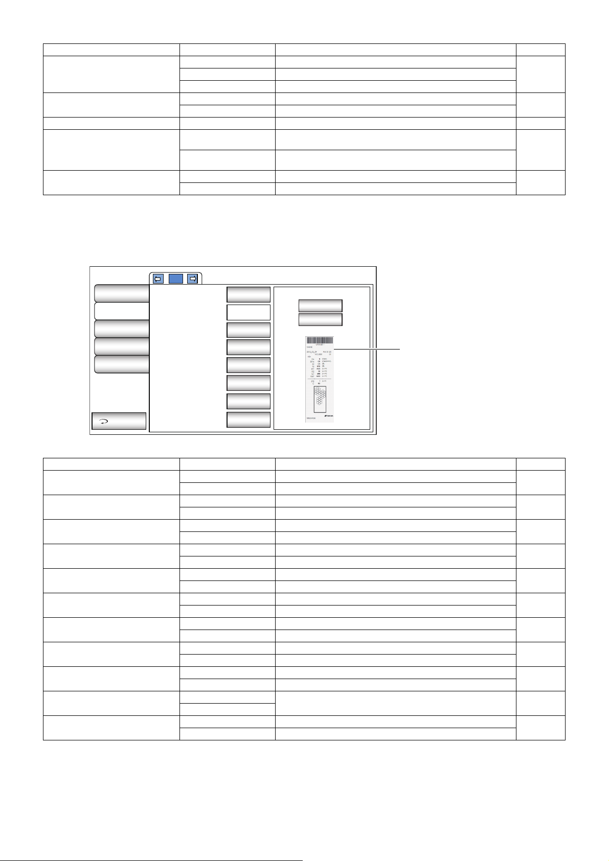
Descriptions Options Details Initial value
Preview of the
set up details
YMD Displayed in Year/Month/Day format.
Date format
DMY Displayed in Day/Month/Year format.
Time format
24h Displayed in 24-hour
AM/PM Displayed in AM and PM
Packing mode Execute Starts packing mode.
The moving direction is changed according
The moving direction is not changed according
XZ MOTOR direction
Patient ID request
Adjust
Fixed
ON Patient ID is required.
OFF Patient ID is not required.
INTERNAL PRINTER
Print contains settings related to output from the internal printer.
1/3
Initial
Settings
Internal
Printer
External
Printer
Network
Settings
Operator
Settings
Exit
Use internal printer
Barcode
Operator ID
Name
Date
Patient ID
Device ID number
Endotherium image
On
On
Off
Off
On
On
-None-
On
Barcode
On
Off
to control panel position.
to control panel position.
DMYMDY Displayed in Month/Day/Year format.
24h
-
Adjust
OFF
Description Options Details Initial value
Use internal printer
Barcode
Operator ID
Name
Date
Patient No.
Device ID number
Endothelium image
Print message
Message
TOPCON logo
ON Internal printer is used.
OFF Internal printer is not used.
ON Barcode is printed.
OFF Barcode is not printed.
ON Operator ID is printed.
OFF Operator ID is not printed.
ON "Name" space is available.
OFF "Name" space is not available.
ON Date is printed.
OFF Date is not printed.
ON Patient No. (Patient ID) is printed.
OFF Patient No. (Patient ID) is not printed.
ON Device ID No. is printed.
OFF Device ID No. is not printed.
ON Endothelium image is printed.
OFF Endothelium image is not printed.
ON Message is printed.
OFF Message is not printed.
-None-
No message
String of up to 72 characters. -None-
ON TOPCON logo is printed.
OFF TOPCON logo is not printed.
ON
OFF
OFF
OFF
ON
ON
ON
ON
OFF
ON
60
SETTING FUNCTIONS ON SETUP SCREEN
Page 63

EXTERNAL PRINTER
556u
56u
1/1
Printer
Paper size
Layout
None
L
Landscape
Initial
Settings
Internal
Printer
External
Printer
Network Settings
Operator
Settings
Exit
Preview of the
set up details
Print contains settings related to output from the external printer.
SP-1P
Specular Microscope
Patient ID: 141421356
Operator ID: 7919
Sex: Male
R
- 1/3
2011/10/31 10:25:03 2011/10/31 10:25:04
Pachy:
Pachy: 2
m
S
S
N T
C
Pleomorphism Graph
Polymegathism Graph
9 or more
0%
1,000 µm2
8
5%
2
750 µm
7
5%
2
6
60%
500 µm
5
25%
2
250 µm
4
0%
5%
3 or less
2
0 µm
Description Options Details Initial value
Printer
None External printer is not used.
CANON CP900 External printer is set to CANON CP900.
Paper size L Paper size is set as L. L
Layout
Landscape Paper orientation is set as landscape (horizontal).
Portrait Paper orientation is set as portrait (vertical).
C
I
I
2/2 - L
m
Pleomorphism Graph
Polymegathism Graph
9 or more
0%
1,000 µm2
8
5%
2
750 µm
7
5%
2
6
60%
500 µm
5
25%
2
250 µm
4
0%
5%
3 or less
2
0 µm
None
Landscape
NETWORK SETTINGS
Network contains settings related to data output via LAN.
Description Options Details Initial value
Use LAN
IP address setting
IP address
Subnet mask
Default gateway
Primary DNS server
Secondary DNS server
Use DICOM
SP-1P port
SP-1P AE Title
Worklist server
Worklist server port
Worklist server AE title
ON LAN connection is on.
OFF LAN connection is off.
Fixed address Assign IP address manually.
DHCP AUTO Assign IP address automatically.
-None-
IP address
-None-
IP address
-None-
IP address
-None-
IP address
-None-
IP address
IP address of PC to output data. -None-
Subnet mask address of SP-1P. -None-
Default gateway address of SP-1P. -None-
Primary DNS Server number. -None-
Secondary DNS Server number. -None-
ON Output to DICOM.
OFF Do not Output to DICOM.
0-65535
Set by ten-key display.
Character string
keyboard
Server name or
IP address
(32 characters)
0-65535
Set by ten-key display.
Character string
Floating keyboard
Port number of using to transmission between
SP-1P and DICOM server.
AE (Application Entity) name of DICOM transmission.
Host name or IP address of the work list server. -None-
Access port number of the work list server. 0
AE name of work list server. (32 characters) -None-
SETTING FUNCTIONS ON SETUP SCREEN
ON
Fixed
address
OFF
0
TOPCON_
SP1P_01
61
Page 64

Description Options Details Initial value
Storage server
Storage server port
Storage server AE title
Query/Retrieve server
Query/Retrieve server port
Query/Retrieve server AE title
Character string
Floating keyboard
0-65535
Set by ten-key display.
Character string
Floating keyboard
Character string
Floating keyboard
0-65535
Set by ten-key display.
Character string
Floating keyboard
Host name or IP address of the work list server. -None-
Access port number of the work list server. 0
AE name of the storage server. -None-
Host name or IP address of Query/Retrieve saver. -None-
Access port number of Query/Retrieve saver. 0
AE name of Query/Retrieve saver (32 characters) -None-
Tranfer syntax Set by pull-down menu Selects data encoding method in DICOM. InplicitVR
Modality Set by pull-down menu Selects a type of modality SC
MWMFilter-AETitle
MWMFilter-Modality
Institution Name
Station Name
Institutional Department Name
ON AE-title is used for MWM filter.
OFF AE-title is not used for MWM filter.
ON Modality is used for MWM filter.
OFF Modality is not used for MWM filter.
Character string
Floating keyboard
Character string
Floating keyboard
Character string
Floating keyboard
Sets the institute name. -None-
Sets the station name. -None-
Sets the institutional department name. -None-
Instance Number Set by ten-key display. Sets the instance number. 0
Export image
ON Report image is exported.
OFF Report image is not exported.
None (String 32char)
Shared folder setting
Folder name
User name
Path and permission to shared folder is set. -None-
Password
Show network information
-
MAC address is shown.
OFF
OFF
OFF
-
Initial
Settings
Internal
Printer
External
Printer
Network
Settings
Operator
Settings
Exit
1/3
Use LAN
IP address setting
IP address
Subnet mask
Default gateway
Primary DNS server
Secondary DNS
server
ON
Fixed
address
0.0.0.0
-None-
-None-
-None-
-None-
ON
OFF
62
SETTING FUNCTIONS ON SETUP SCREEN
Page 65

OPERATOR SETTINGS
OPERATOR contains settings related to Operator ID.
Description Options Details Initial value
Use of operator ID
Prefix of Ope. ID
Operator ID request
Fixed operator ID
Input fixed operator ID
3+1 characters including
13 characters including
ON Operator ID will not be displayed on the control panel and output.
OFF Operator ID will be displayed on the control panel and output.
ASCIIZ string up to
terminated null char.
ON Operator ID is required.
OFF Operator ID is not required.
ON Operator ID is fixed.
OFF Operator ID is not fixed.
ASCIIZ string up to
terminated null char.
OFF
Set the Prefix of Operator ID can be registered. None
OFF
OFF
Input fixed operator ID None
63
SETTING FUNCTIONS ON SETUP SCREEN
Page 66

TROUBLESHOOTING
TROUBLE-SHOOTING OPERATIONS
MESSAGE LIST
"ERROR" Displayed when the photographing is an error.
"Close printer cover" The printer cover is open. Close the cover until it clicks.
"Paper end" Printer paper is used up. Supply printer paper.
"Fatal Error!" Displayed when the printer unit does not operate normally, such as the cutter
does not work. Call the serviceman.
"Patient ID is required.
Please set patient ID."
Displayed when the output operation is requested when the setting "Required
patient ID" is ON but the patient ID is not inputted. Enter the patient ID and
then request the output operation.
"Operator ID is required.
Please set Operator ID."
"LAN hostname error" Failed to resolve the host name of the destination (to be connected with the
"LAN mount error" Failed to connect to the shared folder. Confirm the address, folder name, user
"LAN create Error" Failed in file creation. Confirm that write permission to the share folder is set
"LAN write Error" Failed in writing to the file. Check the free space capacity at the save location.
"LAN stop error" Failed to reset the LAN connection. Confirm that the LAN cable connection and
"LAN restruct error" Failed to reset the LAN connection. Confirm that the LAN cable connection and
"Failed to get IP address." Failed in IP address auto assignment. Set a fixed IP address, or check if the
"Unknown Error" Displayed in case of a LAN error other than the LAN errors mentioned previ-
"IP address conflict" Displayed when the IP address is duplicated.
"Previous photographing data
are left. Please press the Clear
button."
Displayed when the output operation is requested when the setting "Operator
ID request" is ON but the operator ID is not inputted. Enter the operator ID and
then request the output operation.
shared folder). Confirm the inputted host name or DNS server address.
name and password of the destination (to be connected with the share folder).
correctly.
the LAN setting are in the correct way.
the LAN setting are in the correct way.
DHCP server is running.
ously.
Displayed when the output of all output-set data fails.
"Output not set" Displayed when all output settings are OFF.
"Check eyelid" Displayed when the patient's eyelid covers the pupil. Tell the patient to open
their eye as wide as possible.
"Please touch pupil on the
screen"
"TOO CLOSE" Warns that the measuring head is too close to the patient's eye.
"TOO FAR" Warns that the measuring head is too far from the patient's eye.
"Please check the DATE/TIME" The battery for the buit-in clock become run down.
Displayed when the XY position is not aligned. Touch the pupil and bring the
screen to the pupil center.
• Before using, confirm the time and date on the SETUP menu.
• If the message comes up frequently, call your service engineer.
"Chinrest Error" Displayed when the chinrest is not correctly connected or not connected at all.
64
TROUBLESHOOTING
Page 67

"Turn off the unit?" Displayed to confirm whether to move the chinrest and measuring head to their
last positions.
"Please wait until packing mode
is finished..."
"Packing mode is finished.
Please turn off the device."
"First Octet is 1 - 223 Range" Displayed when the first octet of IP address, default gateway, primary DNS
"Value is irregular. Input valid
value"
"The IP address is 0 - 255
Range"
Indicates that the packing operation is in process. Wait until it is completed.
Indicates that the packing operation is completed. Switch off the machine.
server or secondary DNS server is set to a value out of the specified input
range.
Displayed when the octet is set to a value out of the specified input range.
Enter a value within the input range.
Displayed when the subnet mask is set to a value off the input rule. Enter a
value within the input rule.
"At least 3 characters are
required for operator ID prefix."
"Incorrect password" Displayed when the password inputted to select a special mode is incorrect.
"Please don't place the face on
the chinrest, to prepare for next
measurement."
Displayed when the input examiner ID prefix is less than 3 characters. Enter a
prefix with 3 characters.
Displayed to confirm whether to place the face on the chinrest or not, because
the measuring head shall move to the "stand by mode" position of the initial
setting.
65
TROUBLESHOOTING
Page 68

TROUBLE-SHOOTING OPERATIONS
WARNING
To avoid electrical shock, do not open the instrument.
All service should be performed by a qualified service engineer.
If a problem is suspected, use the following check list.
If following instructions does not improve the condition, or if your problem is not included in the list, contact your dealer or TOPCON at the address on the back cover.
CHECK LIST
Trouble Condition Check Page
Control panel does not turn on. Is power cable unplugged? 28
Is power cable connected to the
instrument?
Control panel is not clear. The image is dark. Adjust the brightness by “Control
panel Brightness Adjust”.
Any trouble is found in a movable part.
Printing is not done. Paper comes out without printing. Confirm the direction of paper
Paper does not come out. If “PAPER END” displayed on
Do not move it forcibly but call
our service engineer.
winding. If the direction is incorrect, reset paper to the proper
direction.
control panel, replenish printer
paper.
28
59
89
31
31
66
TROUBLESHOOTING
Page 69

SPECIFICATIONS AND PERFORMANCE
SPECIFICATIONS AND PERFORMANCE
Item Specifications
Corneal endothelium photography
Photography magnification 254x (on the control panel: within ±8%)
Photography range 0.25x0.55mm (within ±8%)
Resolving power More than 125 line/mm
Fixation target Central and peripheral
Corneal thickness measurement
Measurement range 0.400-0.750mm
Display unit: 0.001mm step display
Allowance: Less than 0.600mm within ±0.010mm
Over 0.600mm within ±0.025mm
• Corneal thickness is measured only when taking a photograph using
the central fixation target.
NOTE
Essential performance
• Measurement must be performed correctly.
• Monitor screen display must not be distorted.
67
SPECIFICATIONS AND PERFORMANCE
Page 70

GENERAL INFORMATION ON USAGE AND MAINTENANCE
INTENDED PATIENT POPULATION
The patient who undergoes an examination by this instrument must maintain concentration for a few
minutes and keep to the following instructions:
• To fix the face to the chinrest, forehead rest.
• To keep the eye open.
• To understand and follow instructions when undergoing an examination.
INTENDED USER PROFILE
Since the Specular Microscope SP-1P is a medical device, the operation should be supervised by a
physician.
ENVIRONMENTAL CONDITIONS OF USE
Temperature: 10°C to 40°C
Humidity: 30% to 90% RH(without condensation)
Atmospheric pressure: 700hPa to 1060hPa
STORAGE, USAGE PERIOD
1. Environmental conditions (without package)
*Temperature : 10°C to 40°C
Humidity : 10% to 95% (without condensation)
Air pressure : 700hPa to 1060hPa
* THIS INSTRUMENT DOES NOT MEET THE TEMPERATURE REQUIREMENTS OF ISO
15004-1 FOR STORAGE. DO NOT STORE THIS INSTRUMENT IN CONDITIONS WHERE
THE TEMPERATURE MAY RISE ABOVE 40°C OR FALL BELOW 10°C.
2. When storing the instrument, ensure that the following conditions are met:
(1) The instrument must not be splashed with water.
(2) Store the instrument away from environments where air pressure, temperature, humidity,
ventilation, sunlight, dust, salty/sulfurous air, etc. could cause damage.
(3) Do not store or transport the instrument on a slanted or uneven surface or in an area
where it is subject to vibrations or instability.
(4) Do not store the instrument where chemicals are stored or gas is generated.
3. Normal life span of the instrument:
8 years from delivery providing regular maintenance is performed [TOPCON data]
ENVIRONMENTAL CONDITIONS FOR PACKAGING IN STORAGE
(Product in its normal transport and storage container as provided by manufacturer)
Temperature : -20°C to 50°C
Humidity : 10% to 95%
68
GENERAL INFORMATION ON USAGE AND MAINTENANCE
Page 71

ENVIRONMENTAL CONDITIONS FOR PACKAGING IN TRANSPORTATION
(Product in its normal transport and storage container as provided by manufacturer)
Temperature : -40°C to 70°C
Humidity : 10% to 95%
ELECTRIC RATING
Source voltage: 100-240V AC, 50-60Hz
Power input: 70-120VA
SAFETY DESIGNATIONS PER IEC 60601-1 STANDARD
• Type of protection against electric shocks: Class I
The Class I equipment provides means to connect itself to the protective grounding system of utilities
to thereby independently provide protection against electric shocks by keeping connectable metal
components nonconductive in case of a failure in the basic insulation.
• Degree of protection against electric shocks: B type applied component
The B type applied component provides the specified degree of protection against electric shocks with
regard to the reliability particularly of leak current, patient measuring current and protective utility connection (in case of Class I equipment).
• Degree of protection against harmful intrusion of water (IEC 60529): IPX0
This product does not provide protection against intrusion of water.
(The degree of protection against harmful ingress of water defined in IEC 60529 is IPX0)
• Classification by sterilization/disinfection method specified by manufacturer
This product does not have a component requiring sterilization/disinfection.
• Classification by safety of use in air/flammable anesthetic gas, oxygen or nitrous oxide/flammable anes-
thetic gas atmosphere
• Equipment not suited for use in air/flammable anesthetic gas, oxygen or nitrous oxide/flammable
anesthetic gas atmosphere
• This product should be used in an environment free of flammable anesthetic gas and other flammable gases.
• Classification by operation mode
Continuous operation refers to an operation under normal load conditions, within the specified temper-
ature and without limitations on the operating time.
DIMENSIONS AND WEIGHT
Dimensions: 286~468mm(W) × 445~592mm(D) × 486~681mm(H)
Weight : 17.0kg
69
GENERAL INFORMATION ON USAGE AND MAINTENANCE
Page 72

OPERATION PRINCIPLE
Photography of the corneal endothelium:
Slit light is projected from oblique direction to a patient's eye, and corneal endothelial cells are photographed with the CCD camera optically installed in a diagonal. Image processing of the photographed
corneal endothelial cells is carried out, the boundary of a cell is detected, and the area (Cell density
(CD), Minimum cell area (MIN), Maximum cell area (MAX), Average cell area (AVG), Standard deviation of cell area (SD), Coefficient of variation (CV) and cell area histogram) and the form (Frequency of
hexagon cells (HEX) and form histogram (angle of cell)) are computed.
The boundary line of cell can be corrected (adding, deleting and modifying e.g.) by manual operation.
Cornea thickness measurement:
The slit light is projected onto the patient eye at a slant.
The corneal thickness is measured by processing reflected light from the corneal surface and back,
which is received by line sensor that is optically installed in a diagonal.
70
GENERAL INFORMATION ON USAGE AND MAINTENANCE
Page 73

CHECKPOINTS FOR MAINTENANCE
This symbol is applicable for EU member countries only.
To avoid potential damage to the environment and possibly human health, this instrument should be disposed of (i) for EU member countries - in accordance with WEEE
(Directive on Waste Electrical and Electronic Equipment), or (ii) for all other countries, in
accordance with local disposal and recycling laws.
[WARNING]
This Product Contains Mercury in the backlighting of the LCD display. Prior to disposal remove or
otherwise ensure that this is disposed of in accordance with Local, State and Federal Laws. This
information is applicable in U.S.A only.
This product contains a CRL Lithium Battery which contains Perchlorate Material-special
handling may apply.
See http://www.dtsc.ca.gov/hazardouswaste/perchlorate/
Note; This is applicable to California, U.S.A. only
1. Regularly maintain and check the equipment and parts.
2. When resuming the use after a long period of storage, verify that the instrument operates correctly and safely.
3. To ensure the correct reading, do not mar the photographing window with finger prints, dust, etc.
4. If the photographing window is soiled, clean it following the "CLEANING THE PHOTOGRAPHING WINDOW GLASS" instructions on page 82.
DISPOSAL
When disposing of the instrument and/or parts, follow local regulations for disposal and recycling.
NOTE
GENERAL INFORMATION ON USAGE AND MAINTENANCE
71
Page 74

ELECTROMAGNETIC COMPATIBILITY
The product conforms to the EMC standard (IEC 60601-1-2 Ed3.0:2007)
a)MEDICAL ELECTRICAL EQUIPMENT needs special precautions regarding EMC and needs to be
installed and put into service according to the EMC information provided in the ACCOMPANYING
DOCUMENTS.
b)Portable and mobile RF communications equipment can affect MEDICAL ELECTRICAL EQUIP-
MENT.
c)The use of ACCESSORIES, transducers and cables other than those specified, with the exception
of transducers and cables sold by the manufacturer of the EQUIPMENT or SYSTEM as replacement parts for internal components, may result in increased EMISSIONS or decreased IMMUNITY
of the EQUIPMENT or SYSTEM.
d)The EQUIPMENT or SYSTEM should not be used adjacent to or stacked with other equipment. If
adjacent or stacked use is necessary, the EQUIPMENT or SYSTEM should be observed to verify
normal operation in the configuration in which it will be used.
e)The use of the ACCESSORY, transducer or cable with EQUIPMENT and SYSTEMS other than
those specified may result in increased EMISSION or decreased IMMUNITY of the EQUIPMENT or
SYSTEM.
Item Article code Cable Shielded Ferrite Core Length (m)
AC power cord for (AC120V) 44804 7015 NO NO 1.4
AC power cord for (AC120V) 44804 7017 NO NO 1.4
AC power cord for (AC230V) 44804 2090 NO NO 2.9
AC power cord for (Isolation transformer)
FG cable
LAN cable
USB mouse cable
DC cable for PC AC adapter
AC power cord for PC AC adapter
USB cable
DC cable for Printer AC adapter
AC power cord for Printer AC adapter
-
-
-
-
-
-
-
-
-
NO NO 1.4
NO NO 2.3
NO YES 2.0
YES NO 1.8
NO NO 1.8
NO NO 1.8
YES NO 3.0
NO NO 1.5
NO NO 0.9
Guidance and manufacturer's declaration - electromagnetic emissions
The SP-1P is intended for use in the electromagnetic environment specified below.
The customer or the user of the SP-1P should assure that it is used in such an environment.
Emissions test Compliance Electromagnetic environment - guidance
RF emissions
CISPR 11
RF emissions
CISPR 11
Group 1
Class B
The SP-1P uses RF energy only for its internal function.
Therefore, its RF emissions are very low and are not likely
to cause any interference in nearby electronic equipment.
The SP-1P is suitable for use in all establishments other
Harmonic emissions
IEC61000-3-2
Voltage fluctuations/
flicker emissions
Complies
Complies
than domestic and those directly connected to the public
low-voltage power supply network that supplies buildings
used for domestic purposes.
IEC61000-3-3
72
GENERAL INFORMATION ON USAGE AND MAINTENANCE
Page 75

Guidance and manufacturer's declaration - electromagnetic immunity
The SP-1P is intended for use in the electromagnetic environment specified below.
The customer or the user of the SP-1P should assure that it is used in such an environment.
Immunity test
Electrostatic
discharge(ESD)
IEC 61000-4-2
Electrical fast
transient/burst
IEC 61000-4-4
Surge
IEC 61000-4-5
Voltage dips, short
interruptions and
Voltage variations
on power supply
input lines
IEC 61000-4-11
Power frequency
(50/60 Hz)
magnetic field
IEC 61000-4-8
NOTE U
is the a.c. mains voltage prior to application of the test level.
t
IEC 60601
test level
± 6 kV contact
± 8 kV air
± 2 kV for power
supply lines
± 1 kV for
input/output lines
± 1 kV
line(s) to line(s)
± 2 kV
line(s) to earth
<5% U
t
(>95% dip in Ut)
for 0, 5 cycle
40% U
t
(60% dip in Ut)
for 5 cycles
70% U
t
(30% dip in Ut)
for 25 cycles
<5% U
t
(>95% dip in Ut)
for 5 sec.
3 A/m 3 A/m
Compliance
level
± 6 kV contact
± 8 kV air
± 2 kV for power
supply lines
± 1 kV for
input/output lines
± 1 kV
line(s) to line(s)
± 2 kV
line(s) to earth
<5% U
t
(>95% dip in Ut)
for 0, 5 cycle
40% U
t
(60% dip in Ut)
for 5 cycles
70% U
t
(30% dip in Ut)
for 25 cycles
<5% U
t
(>95% dip in Ut)
for 5 sec.
Electromagnetic environment - guidance
Floors should be wood, concrete or ceramic tile.
If floors are covered with synthetic material, the
relative humidity should be at least 30%.
Mains power quality should be that of a typical
commercial or hospital environment.
Mains power quality should be that of a typical
commercial or hospital environment.
Mains power quality should be that of a typical
commercial or hospital environment. If the user or
the SP-1P requires continued operation during
power mains interruptions, it is recommended
that the SP-1P be powered from an uninterruptible power supply or battery.
Power frequency magnetic fields should be at
levels characteristic of a typical location in a typical commercial or hospital environment.
73
GENERAL INFORMATION ON USAGE AND MAINTENANCE
Page 76

Guidance and manufacturer's declaration - electromagnetic immunity
P
P
P
The SP-1P is intended for use in the electromagnetic environment specified below.
The customer or the user of the SP-1P should assure that it is used in such an environment.
Immunity test
Conducted RF
IEC 61000-4-6
IEC 60601
test level
3 Vrms
150kHz to
80MHz
Compliance
level
3 V
Electromagnetic environment - guidance
Portable and mobile RF communications equipment should be
used no closer to any part of the SP-1P, including cables, than
the recommended separation distance calculated from the
equation applicable to the frequency of the transmitter.
Recommended separation distance
d = 1.2
d = 1.2 80MHz to 800MHz
Radiated RF
IEC 61000-4-3
NOTE 1
NOTE 2
a Field strengths from fixed transmitters, such as base stations for radio (cellular/cordless) telephones and land
mobile radios, amateur radio, AM and FM radio broadcast and TV broadcast cannot be predicted theoretically
with accuracy. To assess the electromagnetic environment due to fixed RF transmitters, an electromagnetic
site survey should be considered. If the measured field strength in the location in which the SP-1P is used
exceeds the applicable RF compliance level above, the SP-1P should be observed to verify normal operation.
If abnormal performance is observed, additional measures may be necessary, such as reorienting or relocating the SP-1P.
b Over the frequency range 150 kHz to 80 MHz, field strengths should be less than 3 V/m.
3 V/m
80MHz to 2,
5GHz
At 80 MHz and 800 MHz, the higher frequency range applies.
These guidelines may not apply in all situations. Electromagnetic propagation is affected by absorption and reflection from structures, objects and people.
3 V/m
d = 2.3 800MHz to 2, 5GHz
where P is the maximum output power rating of the transmitter
in watts (W) according to the transmitter manufacturer and d is
the recommended separation distance in meters (m).
Field strengths from fixed RF transmitters, as determined by
an electromagnetic site survey,
pliance level in each frequency range.
Interference may occur in the vicinity of equipment marked with the
following symbol:
a
should be less than the com-
b
74
GENERAL INFORMATION ON USAGE AND MAINTENANCE
Page 77

Recommended separation distance between
PPP
portable and mobile RF communications equipment and the SP-1P
The SP-1P is intended for use in an electromagnetic environment in which radiated RF disturbances are controlled. The customer or the user of the SP-1P can help prevent electromagnetic interference by maintaining a
minimum distance between portable and mobile RF communications equipment (transmitters) and the SP-1P as
recommended below, according to the maximum output power of the communications equipment.
Separation distance according to frequency of transmitter
Rated maximum output power of
transmitter
W
0, 01 0, 12 0, 12 0, 23
0, 1 0, 38 0, 38 0, 73
11.21.22.3
10 3.8 3.8 7.3
100 12 12 23
For transmitters rated at a maximum output power not listed above, the recommended separation distance d in
metres (m) can be estimated using the equation applicable to the frequency of the transmitter, where P is the
maximum output power rating of the transmitter in watts (W) according to the transmitter manufacturer.
NOTE 1 At 80 MHz and 800 MHz, the separation distance for the higher frequency range applies.
NOTE 2 These guidelines may not apply in all situations. Electromagnetic propagation is affected by absorp-
tion and reflection from structures, objects and people.
150kHz to 80MHz
d = 1.2
80MHz to 800MHz
m
d = 1.2
800MHz to 2,5GHz
d = 2.3
REQUIREMENTS FOR THE EXTERNAL DEVICE
The external device connected to the analog and digital interfaces must comply with the respective
IEC or ISO standards (e.g. IEC 60950-1 for data processing equipment and IEC 60601-1 for medical
equipment).
Anybody connecting additional equipment to medical electrical equipment configures a medical system and is therefore responsible that the system complies with the requirements for medical electrical
systems. Attention is drawn to the fact that local laws take priority over the above mentioned requirements. If in doubt, contact your dealer or TOPCON (see the back cover).
75
GENERAL INFORMATION ON USAGE AND MAINTENANCE
Page 78

PATIENT'S ENVIRONMENT
Do not use multiple outlet strip in the
patient's environment.
Be sure to connect the power supply
to commercial power.
Radius of 1.5m
2.5m
1.5m1.5m
• Personal computer
• Monitor display for PC
• Insulation transformer
• USB flash memory
• Mouse
Suitable device to use in the patient's
environment
When the patient or inspector comes into contact with the devices (including the connecting devices)
or when the patient or inspector is in contact with the person that touches the devices (including the
connecting devices), the patient's environment is shown below.
In the patient's environment, use devices conforming to IEC60601-1. If you are compelled to use any
device not conforming to IEC60601-1, use an insulation transformer or the common protective earth
system.
Note 1: Use the personal computer conforming to IEC60950-1.
Note 2: Don't remove the cover from the personal computer.
Note 3: Use the insulation transformer conforming to IEC60601-1.
CAUTION
• Don't connect an additional power strip or an extension cord to
the system.
• Don't connect any device which is not recognized as one component of the system.
• The total 1kVA is the maximum allowable load of the auxiliary
power supply socket for the insulation transformer, which is provided for the system.
Don't connect the device exceeding this capacity.
• Use the auxiliary power supply socket of the insulation transformer to power only a device that will be a component of the
system.
• It is dangerous to connect any device which is not used as a
component of the system, to the insulation transformer.
• When the insulation transformer is not used, the personal computer and the monitor for the personal computer must be
installed out of the patient's environment.
76
GENERAL INFORMATION ON USAGE AND MAINTENANCE
Page 79

REFERENCE
OPTIONAL ACCESSORIES
• Adjustable instrument table AIT-16
The table height can be adjusted to facilitate measurement.
Specifications
• Dimensions...................525(W)x490(D)mm
• Table height..................660~880mm
• Table size .....................490x500mm
• Weight ..........................approx. 23kg
• Power consumption......150VA (100-120V, 220-240V)
SHAPE OF PLUG
Country Voltage/frequency Shape of plug
Mexico 110V/50Hz Type C&E
Argentina 220V/60Hz Type A
Peru 220V/60Hz Type A
Venezuela 110V/50Hz Type C&E
Bolivia & Paraguay 220V/60Hz
Chile 220V/60Hz Type A
Colombia 110V/50Hz Type C
Brazil
Ecuador 110V/50Hz Type C&E
USA 120V/60Hz Type A (Hospital Grade)
Canada 120V/60Hz Type A (Hospital Grade)
220V/60Hz
127V/60Hz
Type A (Most common)
Type H (Infrequently)
Type A
Type C
77
REFERENCE
Page 80

MAINTENANCE
MAINTAINING ACCURACY
PHOTOGRAPHING WINDOW
When the lens of the photographing window is dirty, the control panel may be hard to view or a clear
image may not be obtained. Make sure that the photographing window is not dirty before using theinstrument. If the photographing window is dirty, clean it.
(See page 82 "CLEANING THE PHOTOGRAPHING WINDOW GLASS".)
BRIGHTNESS ADJUSTMENT OF CONTROL PANEL
• The control panel is optimally adjusted when shipped.
• For control panel brightness adjustment, see "INITIAL SETTINGS," "Control panel brightness"
(page 59).
DAILY CHECKUPS
DAILY MAINTENANCE
• For this instrument, dust may cause errors. When not in use, replace the measuring lens cap and
dust cover.
• When not in use, turn off the POWER switch.
When using the dust cover, tap the Reset button and return the chinrest and
NOTE
ORDERING CONSUMABLE ITEMS
• When ordering consumable items, tell the product name, product code and quantity to your dealer
or TOPCON at the address of back cover.
Product name Product code Product name Product code
Chinrest tissue 40310 4082 Printer paper 44800 4001
Silicon cloth 44800 1001
Dust cover 42360 9002
measuring head to their initial positions.
78
MAINTENANCE
Page 81

USER MAINTENANCE ITEM
Item Inspection time Contents
Inspection Before using
Cleaning When the part is stained
Replacement As required • Printer form
MANUFACTURER MAINTENANCE ITEMS
Item Checking time Contents
Cleaning each
component
Operation check Within 12 months
Accuracy check Within 12 months
Within 12 months
• The instrument works properly.
• The photographing window must be free of
stain or flaw.
• Photographing window
• External cover, control panel, etc.
• Cleaning outer covers
• Checking the optical system
• Cleaning POWER unit
• Checking the main body operation
• Checking switches
• Confirming the corneal endothelium analyzing
functions (using special tools)
• Confirming the cornea thickness measurement
functions (using special tools)
79
MAINTENANCE
Page 82

PRINTER PAPER JAM
• To avoid failure or potential injury, do not open the printer cover
while the printer is in operation.
• To avoid potential injury in case of malfunction, including a paper
jam, be sure to shut off the power before attempting to repair it.
CAUTION
NOTE
If the printer paper is jammed in the printer, printing will stop and the jam
should be cleared.
• To avoid potential injury, do not touch the printer body including
metal parts or the paper cutter, while the printer is in operation or
when replacing the printer paper.
• Pay much attention not to touch the internal printer's body when
the cover is open. If touched, it may result in trouble due to electrostatic discharge.
1 Open the printer cover, and take out the jammed paper pieces.
NOTE
After removing the jammed printer paper, tap the Print button to print out the
previous measurement data.
If no previous measurement data has saved, a blank sheet is printed out.
80
MAINTENANCE
Page 83

SUPPLYING THE CHINREST TISSUE
Chinrest tissue pins
Chinrest
tissue
• When the chinrest tissue has run out, pull off chinrest tissue pins and place new tissue.
81
MAINTENANCE
Page 84

MAINTENANCE
How to move the applicator
How to wipe the lens or glass
CAUTION
• To avoid damage to the instrument or electric shock, turn the power switch
OFF and unplug the power cord before maintenance.
• Avoid spraying a cleaner directly onto the instrument. In such a case,
NOTE
CLEANING THE INSTRUMENT
• Dust on photographing window glass.....Blow off dust with a blower.
• Fingerprints and oil spots on photographing window glass
• Dirty instrument cover...................... Wipe the surface with the attached silicon cloth or a dry soft
detergent or any other fluid may permeate through the vent hole, etc.
which can cause mechanical problems with the instrument.
• When not in use, turn off the power switch.
• Do not clean plastic parts with solvents. Benzine, thinner, ether and gasoline may cause discoloring and decomposition.
To avoid electric shocks, make sure the power is off and the power
cable is unplugged before maintenance.
Blow off dust with a blower and wipe the surface gently with a
camera lens cleaner using clean gauze.
cloth. Never use solvents or a chemical duster.
CLEANING THE PHOTOGRAPHING WINDOW GLASS
• To secure auto alignment and correct photographing values, clean the photographing window
glass after each day's work.
• Clean the glass when "CLEAN THE PHOTOGRAPHING WINDOW GLASS" is displayed on the
control panel screen.
1 Prepare a lens cleaner.
2 Using a blower, blow off any dust from the surface of the lens or glass.
3 Moisten an applicator with the lens cleaner.
4 Lightly wipe the lens from its center point toward the outside in a swirl, using the applicator.
82
MAINTENANCE
Page 85

5 If all the stains cannot be removed, repeat this procedure a few times.
• Don't wipe the photographing window using a commercial tissue, etc. This
may make the photographing window dirtier.
NOTE
• Don't wipe the photographing window using gauze held with tweezers.
This may damage the surface of the lens or glass.
• Replace new applicator and repeat cleaning.
6 It is complete when stains can be wiped off finely. If the stains are still hard to remove, contact
your dealer or the TOPCON sales department.
CLEANING THE COVER
Do not clean plastic parts with solvents. Benzine, thinner, ether and gasoline
NOTE
may cause discoloring and decomposition.
1 If the cover get soiled, wipe the surface with dry cloth.
2 If the cover is noticeably stained, wipe the surface with a damp cloth which is moistened in a
tepid water solution of neutral detergent.
CLEANING THE CONTROL PANEL
• As the control panel screen is a touch panel, be sure to turn off the
POWER switch before wiping. The touch panel will react and malfunction.
NOTE
CONTAMINATION BY DUST
Remove the dust with a soft brush, and wipe with the attached monitor cleaner.
CONTAMINATION BY FINGERPRINTS
Wipe with the attached monitor cleaner.
If the stain still remains, moisten the monitor cleaner with water and then wipe off the stain.
• When the monitor cleaner has become dirty, wash it. When washing, rinse
it thoroughly so no detergent is left. If the detergent is left, it may cause
uneven wiping.
CLEANING THE FOREHEAD REST AND CHIN REST
• Wipe the forehead rest and the chin rest with a cloth moistened with a tepid solution of neutral
detergent for kitchenware.
MAINTENANCE
83
Page 86

SP-1P SOFTWARE LICENSE TERMS
PLEASE READ THE FOLLOWING “LICENSE TERMS” CAREFULLY BEFORE USING OR INSTALLING
THIS SOFTWARE!
This software includes the "Qt" software licensed by Digia Plc (Head office: Finland).
ANY AND ALL TERMS AND CONDITIONS OF THE “LICENSE TERMS” SHALL BE DEEMED TO BE
ACCEPTED AND AGREED BY YOU IF YOU USE THIS SOFTWARE.
The SP-1P Software, including its instruction manual and other documents, contained in this package
comprises copyrightable works of TOPCON CORPORATION protected by copyright laws and is licensed,
not sold. Digia Plc and its licenser posses the copyright and the intellectual property right of the "Qt" software installed in SP-1P.
TOPCON CORPORATION grants to you the right to use this SP-1P Software under the terms and conditions outlined below.
LICENSE TERMS
1. LICENSE
Subject to the terms and conditions outlined in these LICENSE TERMS, TOPCON CORPORATION
("TOPCON") hereby grants to you ("USER") a non-exclusive and non-transferable license
("LICENSE") to use the SP-1P SOFTWARE (including the "Qt" software ("Qt")) including its instruction
manual and other documents (separately or collectively the "SOFTWARE") only on the SP-1P instrument you use ("INSTRUMENT").
2. RESTRICTION
2.1 USER shall NOT:
(a) use the SOFTWARE on or with any computer or machine other than the INSTRUMENT, or
(b) make any copy of part or whole of the SOFTWARE and distribute the copy; or
(c) disclose this software to the third party; or
(d) sell, assign, exchange, pass, rent, lease or otherwise dispose of the SOFTWARE, or assign or
sub-license any right to use the SOFTWARE to anyone else; or
(e) adapt, modify or alter the SOFTWARE, or merge any program with the SOFTWARE, or make any
derivative or secondary copyrighted work from the SOFTWARE; or
(f) remove, erase or make unclear any copyright notice of the SOFTWARE; or
(g) analyze or make reverse-engineering to, the SOFTWARE by decompiling or disassembling it; or
(h) make a copy of the instruction manual and other documents contained in this package.
3. EXCHANGING OF MEMORY MEANS, ETC.
3.1 If USER desires to exchange the INSTRUMENT’s internal memory means in which the SOFTWARE
has been installed, USER shall so notify TOPCON in writing directly or through its subsidiary, affiliate,
distributor or agent prior to said reformat, etc. TOPCON will replace the memory means if necessary.
84
SP-1P SOFTWARE LICENSE TERMS
Page 87

3.2 IN NO EVENT SHALL TOPCON OR ITS SUBSIDIARIES, AFFILIATES, DISTRIBUTORS OR
AGENTS BE RESPONSIBLE OR LIABLE FOR ANY DAMAGES OR LOSSES ARISING OUT OF,
RESULTING FROM OR IN CONNECTION WITH ANY OF THE ACTS MENTIONED ABOVE IF IT IS
DONE BY USER WITHOUT SAID NOTICE, OR IN NON-COMPLIANCE WITH ANY INSTRUCTION
FROM TOPCON.
4. COPYRIGHT
The SOFTWARE is the exclusive property of TOPCON, and full title, ownership and interests and
copyrights thereof shall remain vested with TOPCON at any and all times. Digia Plc and its licenser
posses the copyright and the intellectual property right of Qt.
5. TERM
These LICENSE TERMS shall commence on the date when the SOFTWARE is first used by USER,
and shall remain in full force until the termination hereof pursuant to the provisions set out in Section
6.1 below.
6. TERMINATION
These LICENSE TERMS shall be forthwith terminated if:
6.1 (1) USER decides to cease use of the INSTRUMENT (in this event, USER shall, without delay, notify
TOPCON in writing of such decision); or
(2) USER fails to comply with any term or condition of these LICENSE TERMS.
6.2 Upon any termination of these LICENSE TERMS, USER shall immediately cease to use the INSTRUMENT in any manner. Any memory paid by USER shall not be refunded after use or installation by
USER of the INSTRUMENT for any reason whatsoever including any termination of these LICENSE
TERMS.
6.3 Any and all provisions set out in Sections 3.2, 4, 6.2 and 7 through 11 shall survive any termination of
these LICENSE TERMS.
7. LIMITED WARRANTY
7.1 In the event that a hidden material defect is found by USER, USER shall notify TOPCON in writing of
such defect directly or through its subsidiary, affiliate, distributor or agent within ninety (90) days after
USER has received the SOFTWARE. TOPCON shall, at its sole discretion, elect to either repair such
defect, or exchange with new software, with no charge to USER, subject to the condition that TOPCON has confirmed the existence of such defect which is attributable to TOPCON and has judged
that such defect is material.
TOPCON shall not be liable for any and all obligations under this Section 7.1 if
(1) the hidden defect is not notified within said ninety (90)-day period, or
(2) any defect has arisen out of, resulted from or in connection with any abuse, misuse, acci-
dent, neglect or unauthorized use or repair, or any other improper use, etc. which is not
attributable to TOPCON.
TOPCON shall not give any warranty to the USER for "Qt" instead of Digia Plc, regardless of
Section 7.
85
SP-1P SOFTWARE LICENSE TERMS
Page 88

7.2 THE SOFTWARE IS PROVIDED ON AN “AS IS” BASIS WITHOUT WARRANTY OF ANY KIND.
TOPCON FURTHER DISCLAIMS ALL WARRANTIES, INCLUDING, WITHOUT LIMITATION, ANY
IMPLIED WARRANTIES OF MERCHANTABILITY, FITNESS FOR A PARTICULAR PURPOSE AND
NON-INFRINGEMENT, EXCEPT AS OTHERWISE EXPRESSLY PROVIDED HEREIN.
THE ENTIRE RISK ARISING OUT OF, RESULTING FROM OR IN CONNECTION WITH THE USE
OR PERFORMANCE OF THE SOFTWARE REMAINS WITH THE USER. IN NO EVENT SHALL
TOPCON OR ITS SUBSIDIARIES, AFFILIATES, DISTRIBUTORS OR AGENTS BE LIABLE FOR
ANY CONSEQUENTIAL, INCIDENTAL, DIRECT, INDIRECT, SPECIAL, PUNITIVE, OR OTHER
DAMAGES WHATSOEVER (INCLUDING, WITHOUT LIMITATION, DAMAGES FOR LOSS OF BUSINESS PROFITS, BUSINESS INTERRUPTION, LOSS OF MEDICAL, CLINICAL OR BUSINESS
INFORMATION, OR OTHER PECUNIARY LOSS, OR PERSONAL INJURY OR PROPERTY DAMAGE) ARISING OUT OF, RESULTING FROM OR IN CONNECTION WITH THESE LICENSE
TERMS OR THE USE OF OR INABILITY TO USE THE SOFTWARE.
8. COMPLIANCE WITH EXPORT CONTROL LAWS
Any and all exports or re-exports of the SOFTWARE are subject to Japanese Exchange and Foreign
Trade Law and other Japanese-related laws and regulations, and/or the United States Export Administration Act, its implementing regulations as well as other U.S. export laws and regulations. Export or reexport of the SOFTWARE in a manner contrary to either Japanese or U.S. law or regulation is strictly
prohibited.
USER shall not export nor re-export to any country the SOFTWARE or any part or copy thereof without
first obtaining all required authorization from the Japanese or United States government.
In addition, with respect to export and re-export of the SOFTWARE, USER shall observe and comply
with any other applicable export laws and regulations of any other countries and shall not export nor reexport to any country the SOFTWARE or any part or copy thereof in a manner contrary to any other
applicable export laws and regulations of any other countries.
TOPCON OR ITS SUBSIDIARIES, AFFILIATES, DISTRIBUTORS AND AGENTS SHALL NOT BE
RESPONSIBLE NOR LIABLE TO USER FOR ANY LIABILITY, LOSS, DAMAGE, PUNISHMENT, OR
PENALTY ARISING OUT OF OR RESULTING FROM USER'S VIOLATION OF OR NON-COMPLIANCE WITH ANY JAPANESE, U.S. OR OTHER APPLICABLE COUNTRY'S EXPORT CONTROL
LAWS OR REGULATIONS.
9. ADDENDUM STIPULATIONS OF Qt
The USER shall understand and agree to the following items about Qt.
(1) Qt is not designed, intended or licensed to be used in the machines or for the purposes described
below;
- any system, device or product that will be used for the surgical implantation, the life-saving or life-
supporting application and the air craft or atomic furnace;
- any application in which the defects, improper operation or malfunction of Qt may cause any injury,
death or direct/indirect serious damage to properties.
(2) The USER shall be responsible to check the compatibility of Qt for the relevant situation or applica-
tion.
86
SP-1P SOFTWARE LICENSE TERMS
Page 89

(3) These LICENSE TERMS provide the distribution of risk between Qt and the USER. The risk distribu-
tion is effectuated in the fare needed for the license (the price equivalent to it).
10. GOVERNING LAW
The validity, performance, construction, interpretation, effect and enforcement of these LICENSE
TERMS shall be governed by and under the laws of Japan.
11. ENTIRE AGREEMENT
These LICENSE TERMS constitute the entire agreement between USER and TOPCON with respect to
the subject matter hereof, and shall supersede and cancel any and all prior written or oral agreements,
undertakings, negotiations, communications, commitments, representations, publications and advertisement, etc. not specifically and expressly incorporated herein.
12. OPEN SOURCE SOFTWARE
The following open source softwares are packaged with this product. For each open source software,
follow its license terms.
IPA font: http://ipafont.ipa.go.jp/
bzip2: http://www.bzip.org/
e2fsprogs: http://e2fsprogs.sourceforge.net/
87
SP-1P SOFTWARE LICENSE TERMS
Page 90

Page 91

Please specify the following when contacting us regarding questions about
this operation microscope.
● Model name: SP-1P
● Serial No.: Marked on the rating nameplate.
● Period of use: Please inform us of the date of purchase.
● Defective condition: Please provide us with as much detail as possible.
SPECULAR MICROSCOPE SP-1P
USER MANUAL
2013 version (2013.08-100LW0)
Date of issue: August 1st, 2013
Published by TOPCON CORPORATION
75-1 Hasunuma-cho, Itabashi-ku, Tokyo, 174-8580 Japan.
©2013 TOPCON CORPORATION
ALL RIGHTS RESERVED
Page 92

SPECULAR MICROSCOPE
SP-1P
41904 97030
Printed in Japan 1308-100LW0
 Loading...