

Page 1
1
ST8
Manual V1.0
2019.09
www.toolkitrc.com
ToolkitRC Technology (Shenzhen) Co.. Ltd.
@ToolkitRC 2019
Page 2
2
Thanks
Tips
Important
Information
Thank you for purchasing the ST8 Multi-function
servo tester. Please read this manual carefully before
use.
Key Points
Further Information
To ensure you have a more enjoyable experience,
please use WeChat to scan the QR code below and use
it to get the usage details, video teaching and latest
information. Or visit www.toolkitrc.com.
WeChat QR Code
@ToolkitRC 2019
Page 3

3
Safety Precautions
1, The ST8 allows input voltage of 7-28V. To ensure that
the power supply voltage is consistent, pay attention to
the positive and negative polarity of the power supply
when connecting.
2, The S1-S4,S4 Ext. signal ports only support a
maximum of 2A current. For a larger current servo,
connect the output main port to prevent the internal
circuit from being burned out.
3, The S1-S4 signal port can only output up to 8.4V, for
higher voltage uses the main port.
4, Do not use this product in heat, humidity, flammable
or explosive atmosphere.
5, Do not leave this product unattended while in use to
prevent accidents.
6, Please unplug the input power when not use this
product.
@ToolkitRC 2019
Page 4

4
Contents
Thanks
Key Points
Further Information
Contents
First start
Main interface
Pause interface
Channel setting
...................................................................
.............................................................
..............................................
................................................................
...............................................................
.......................................................
..................................................
..................................................
1,Signal source setting
2,P1 source setting
3,S5 source setting
4,Internal source setting
5,Key setting
................................................
6,S 1 source setting
7,Output source setting
...............................
......................................
.....................................
............................
....................................
.............................
2
2
2
4
7
8
10
11
11
11
12
14
16
16
17
System setting
....................................................
@ToolkitRC 2019
17
Page 5

5
Product overview
The ST8 is a product for testing servos, with up to 28V
voltage output, 8-channel signal output, current
measurement, curve display and other functions.
4 channels of programmable independent signal, 8
channels of signal output, accuracy of 1 ms.
4 independent current acquisition, respectively,
curve display.
Multiple measurement modes (speed, count, step,
linear).
output PWM signals with a period of 33 to 1000 Hz.
A variety of signal trigger sources (internal, buttons,
knobs, external sources).
Measure the response speed of the steering gear
with an accuracy of 1 millisecond.
The external input signal supports PWM/ PPM/
SBUS with an accuracy of 1 ms.
The external input signal supports PWM/ PPM/
SBUS with an accuracy of 1 ms.
Drive the servo with a maximum load of 100W.
Multi-language system, you can upgrade the
language you need.
The device is simulated as a USB flash drive, and
the upgrade file is copied to implement product
firmware upgrade.
@ToolkitRC 2019
Page 6
6
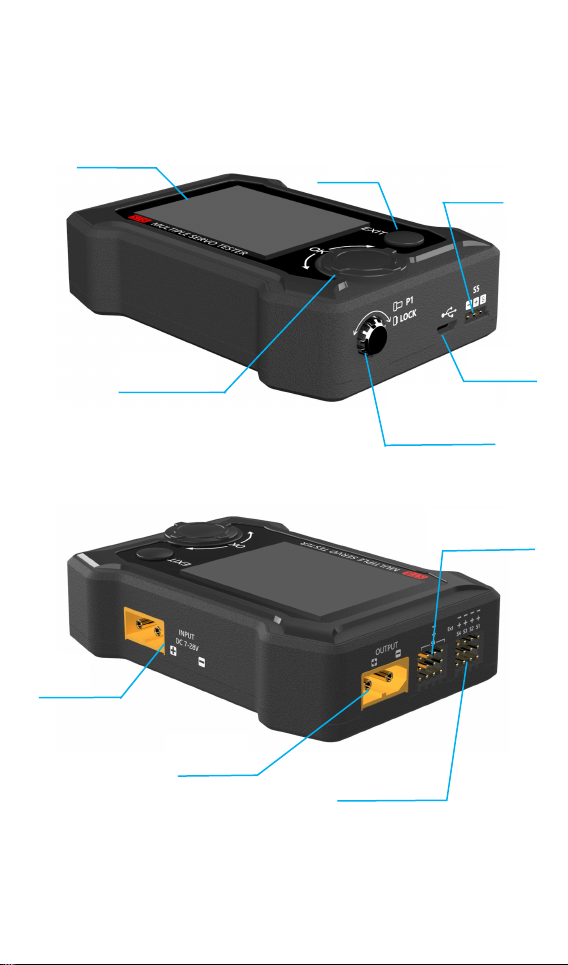
ST8 Layout
Display
Exit
USB port
P1 knob
(press,lock)
Input
Output
S4 Ext. port
Knob(OK)
S1-S4 port
S5 port
Front
Back
@ToolkitRC 2019
Page 7
7
First start
1, the 7-28V power supply is connected to the input port
on the back of the ST8
2, the display shows the boot logo and stays for 2
seconds
3, accompanied by do-re-mi boot sound
4, the boot is completed, the display enters the main
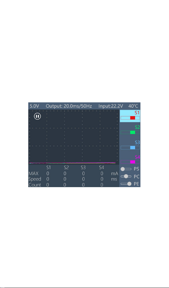
interface as shown below:
5, Press [Exit] to start the PWM signal output and test.
6, Rotate [Knob], move the cursor to select different
channels, press [OK] to confirm, pop up the setting
options of the selected channel, and set the input and
output signals of the channel.
7, Press and hold [OK] to enter the system setup menu.
8, Press [Exit] to end the modification or return to the
main interface.
@ToolkitRC 2019
Page 8
8
=================================
2, Press and hold [Knob] for 2 seconds to set the
function for entering the system.
3, Short press 1 [Exit], pause, start, exit function.
1, Short press 1 [Knob], to determine the key function.
4, Successfully operate any key, have didi prompt
tone.
===================================
Main interface
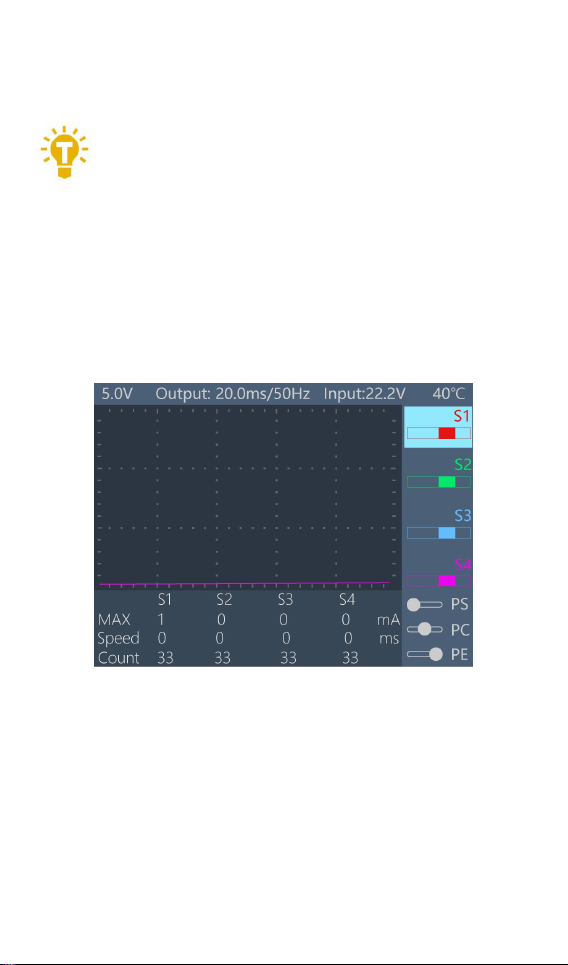
After pressing the [Exit] button after powering on,
the system shows the main interface, as shown below:
The top 5.0V is the output voltage of the main port
or PWM output port. When the main port voltage is off,
the voltage of the PWM output port will be displayed in
black. When the main port voltage is turned on, the
main port voltage will be displayed in red. The output
20.0ms/50Hz is the PWM output frequency and period.
Input 9.7V is the input voltage. Below the minimum
input voltage set by the system, it will alarm and flash
@ToolkitRC 2019
Page 9

9
red. 41 ° C is the motherboard temperature, higher than
the safe temperature set by the system will alarm and
flash red.
The right side S1, S2, S3, and S4 are independent
4-channel PWM signals, which are distinguished by
different colors and graphically display the pulse width
value.
The middle grid is a curve display of 4 PWM output
current, which is easily distinguished by the
corresponding color display on the right side.
Below is the output bar, which outputs the
maximum current, speed, and count of each channel in
real time.
The PS, PC and PE buttons are in the lower right
corner. When the button source mode is selected, the
buttons will become selectable.
@ToolkitRC 2019
Page 10
10
Pause interface
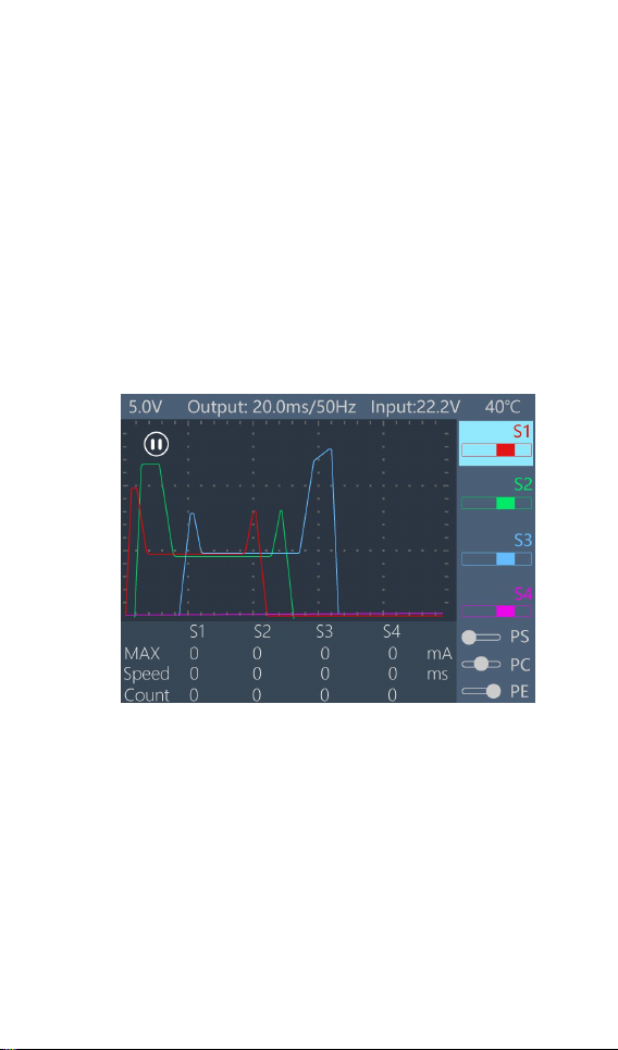
After booting up or pressing [Exit] on the main
interface, you can enter the pause interface, as shown
below:
When paused, the current curve is paused and the
PWM signal is maintained at a fixed value. Rotate [Knob]
to adjust the timeline to view the saved current curve.
Press [Exit] to exit the pause interface.
@ToolkitRC 2019
Page 11
11
Channel setting
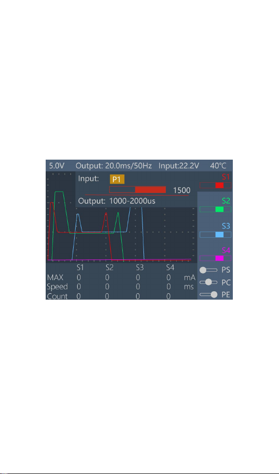
After selecting a channel in the main interface, press
[OK] to pop up the setting options of the selected
channel, and the following interface is displayed.
1,Signal source setting
Rotate the [Knob], move the cursor to the [Input] [P1]
position, press [OK] to modify the source setting.
Channel 1 can be set to P1, S5, internal signal, button,
and 4 sources. Channels 2-4 can be set to P1, S5,
internal signals, buttons, channels 1, and 5 sources. After
selecting the appropriate source. Short press [OK] and
[Exit] to take effect.
2,P1 source setting
@ToolkitRC 2019
Page 12
12
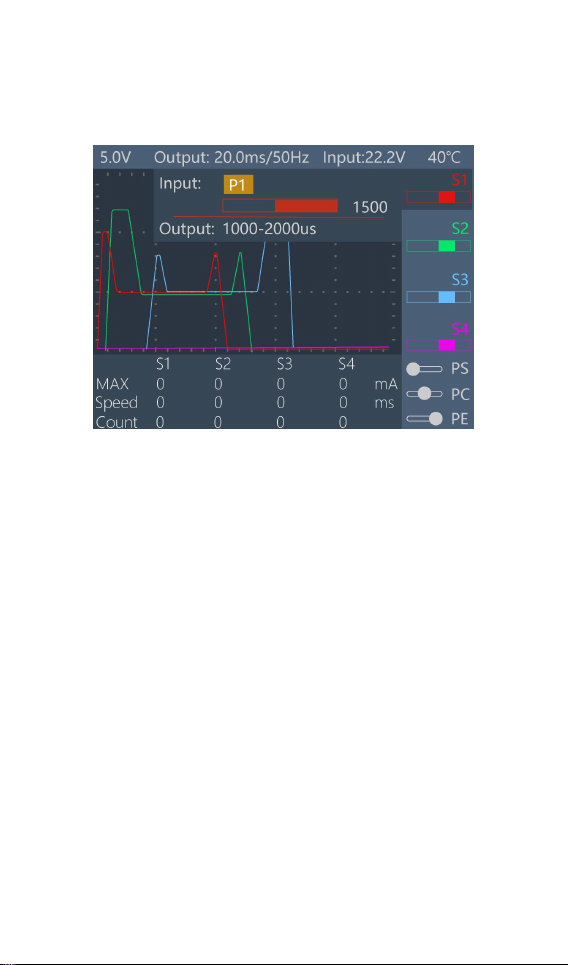
When the P1 source is selected, the PWM output
can be controlled by the P1 knob and the position of the
knob can be displayed. As shown below:
3,S5 source setting
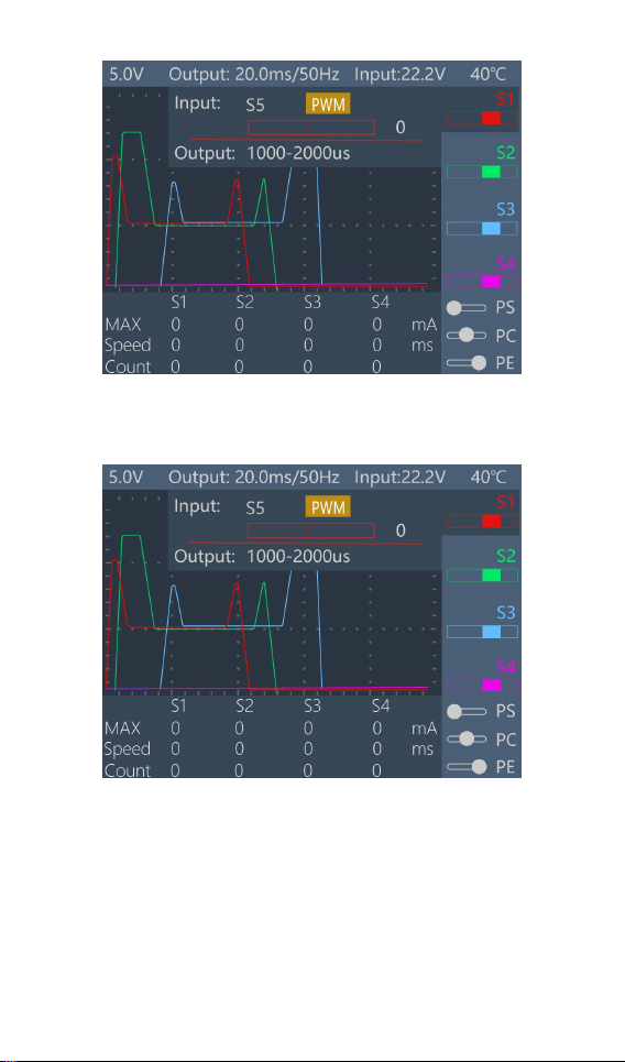
When S5 is selected as the signal source, PWM,
PPM, and SBUS signals can be selected. By inputting the
corresponding signal on the S5 interface, the received
signal value can be displayed and the PWM output can
be controlled.
When the PWM signal is selected, as shown below:
@ToolkitRC 2019
Page 13
13
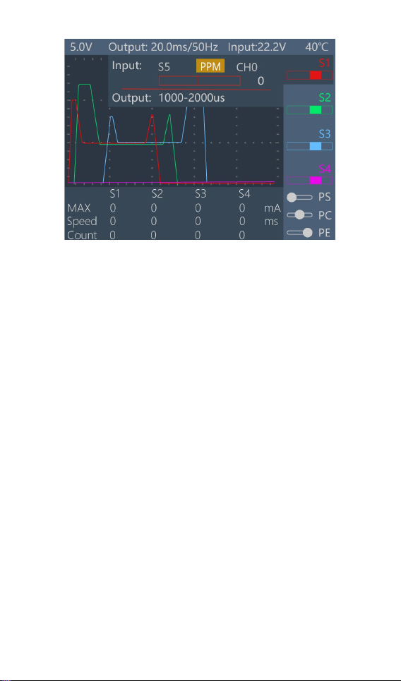
When the PPM signal is selected, the channel can
be set from CH0 to CH7, as shown below:
When the SBUS signal is selected, the channel can
be set from CH0 to CH15. As showed below:
@ToolkitRC 2019
Page 14
14
4,Internal source setting
When the signal source selects the internal signal, it
can be set to linear and phase modes. These two modes
are mainly used for the aging servo test, which will
generate a count and will stop working when the set
value is reached. It can be turned off in the system
settings.
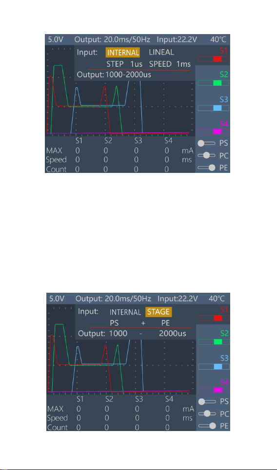
When the linear mode is selected, you need to set
the step value and speed value. The step value ranges
from 1 microsecond to 10 microseconds, and the speed
value ranges from 1 millisecond to 10 milliseconds.
Taking 1 respectively means adding 1 microsecond
or 1 microsecond each time in the range of the PWM
signal output at a speed of 1 ms. As showed below:
@ToolkitRC 2019
Page 15
15
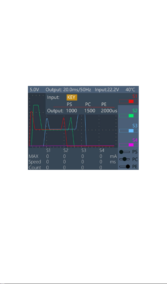
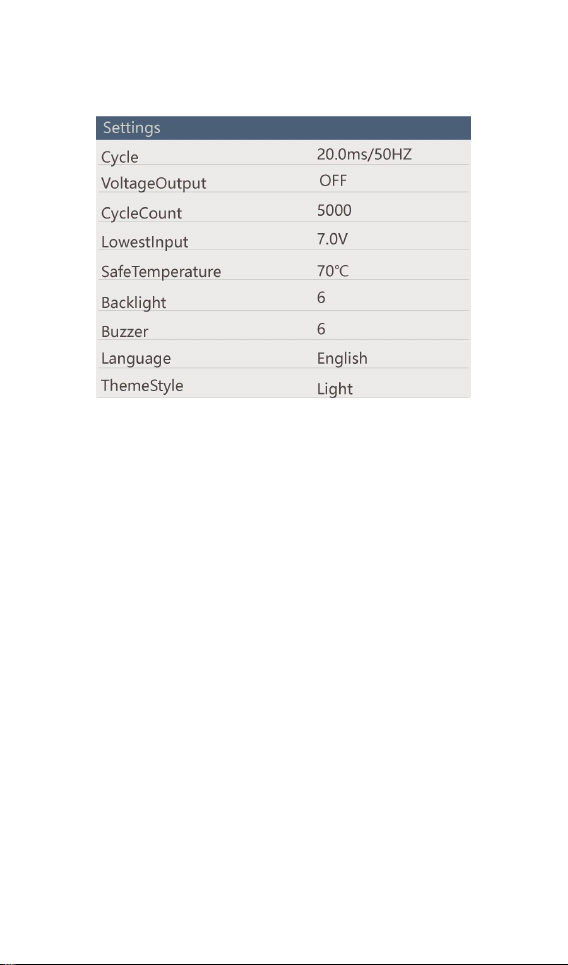
When the phase mode is selected, if the PC point is
not enabled, it is the second-order mode, which jumps
between the two values of PS and PE at 1 second. If the
PC point is enabled, it is the third-order mode, which
jumps between the three values of PS, PC and PE at 1
second. This mode allows you to measure the response
speed of the steering gear. As shown below:
@ToolkitRC 2019
Page 16
16
5,Key setting
When the signal source selects the button, the main
interface will display PS, PC, PE buttons, you can move
the cursor to the buttons on the main interface and
short press [OK] to output the corresponding PWM
value. The time to turn the angle can be measured and
displayed. As shown below:
6,S1 source setting
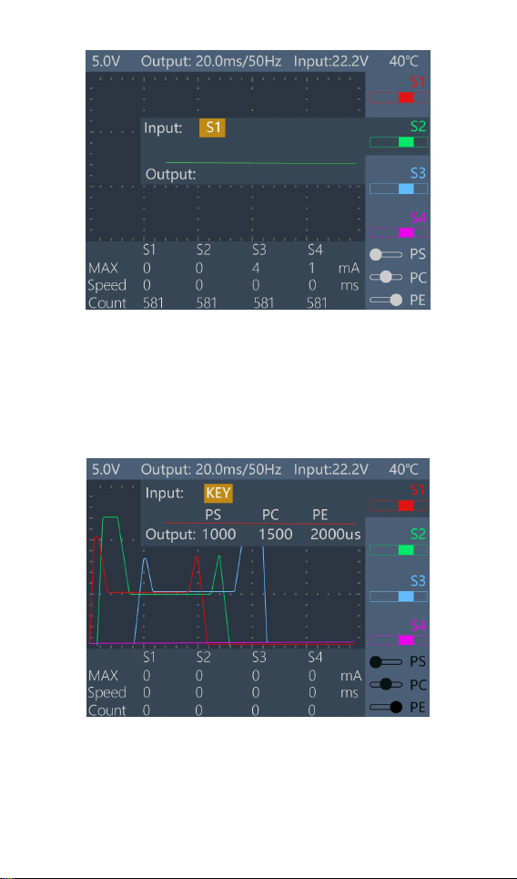
When S2, S3, S4 signal source selects S1, it will
follow the S1 setting and output S1 with the same PWM
value.As shown below:
@ToolkitRC 2019
Page 17
17
7,Output source setting
Move the cursor to the [Output] position to set the
range of the PWM output signal with an accuracy of 1
microsecond. If you are in the button source and internal
source stage modes, you need to set the PC value.
System setting
Press [OK] on the main interface for 2 seconds to
@ToolkitRC 2019
Page 18
18
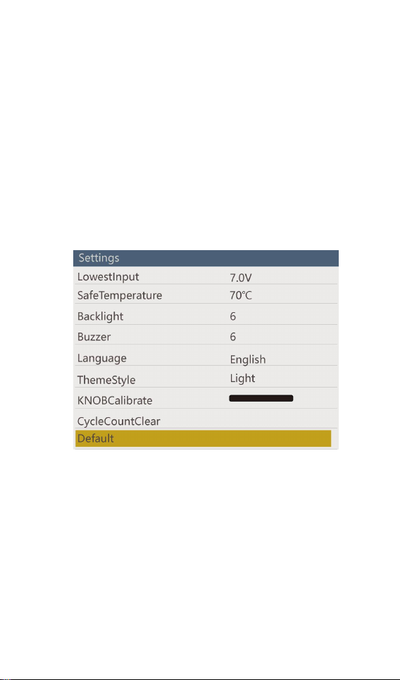
enter the system setting interface, and rotate [Knob] to
switch the corresponding settings, as shown below:
Cycle: Output the period of the PWM signal, ranging
from 1 millisecond to 30 milliseconds.
VoltageOutput : The output voltage of the main port has
11 gears, including turnoff, 5V, 6V, 7.4V, 8.4V, 12V, 14V, 15V,
16V, 18V, 24V, 28V. When it is turnoff, the main port does
not output voltage, the PWM output port voltage is 5V,
and the load power is 15W. If the load power exceeds
the load, it will prompt “Please turn on the main port
power”. For 5.0V-8.4V, the main port and PWM output
ports are 5.0V-8.4V. For 12V-28V, the main port output
voltage is 12V-28V, and the PWM output port is 5V,
which can drive large servos.
CycleCount: When using the internal signal source, a
count will be generated, and when the set number of
work times is reached, the operation will stop.
LowestInput: Below this voltage, the device will stop the
@ToolkitRC 2019
Page 19
19
main port output.
SafeTemperature: Above this temperature, the device
will stop the main port output.
Backlight: The backlight brightness level of the display
can be set to 1-10.
Buzzer: The tone of the buzzer can be set to off.
Language: The system displays the language. English
and Chinese can be selected.
ThemeStyle: The color style displayed by the system
interface. It is divided into bright and dark colors.
KNOB Calibration: Jump the P1 knob to the calibration of
the maximum and minimum implementation knobs.
CycleCountClear: Clear the count under the internal
source.
Default : Restore all settings to factory defaults.
Other functions
Firmware upgrade:
@ToolkitRC 2019
Page 20
20
After connecting the ST8 to the computer via the
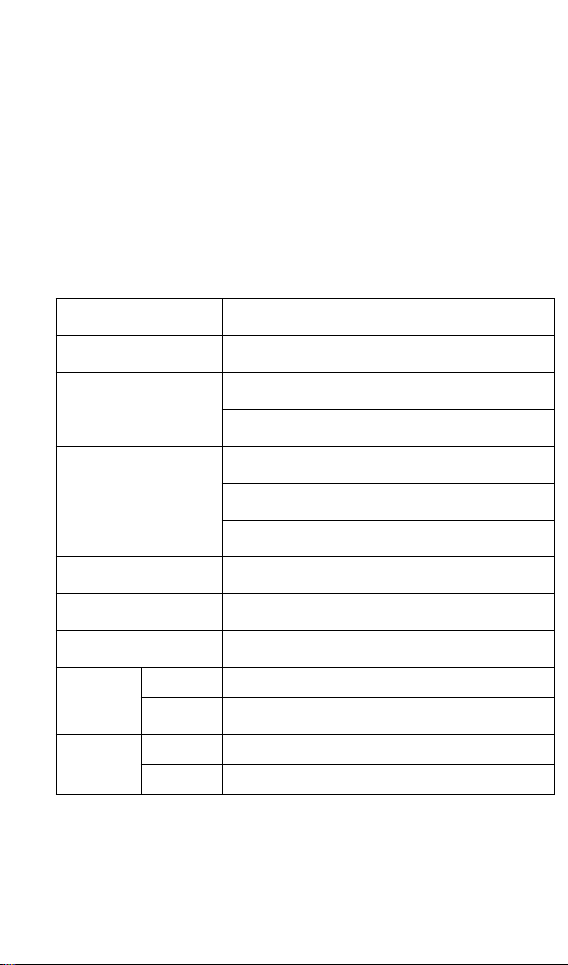
Input voltage
7-28V@MAX 10A
Main output port
5.0V-28.0V@MAX 10A
Signal port
Output voltage
5.0V-8.4V@MAX 4A/S1-S4
5.0V-8.4V@MAX 4A/S4 Ext.
Output signal
100us-2900us@33-1000Hz @S1-S4
PWM 500us-2500us@S5
PPM 8CH@S5 SBUS 16CH@S5
P1 rotation range
1000us-2000us@P1
MicroUSB
LCD display
2.4 inch TFT RGB 320*240 resolution
Product
Size
99mm*68mm*26mm
Weight
120g
packing
Size
105mm*80mm*45mm
Weight
200g
USB cable in the box. the computer will recognize the
USB flash drive named Toolkit. Download the upgrade
file app.upg on the official website to overwrite the
files in the USB flash drive to upgrade the firmware.
Specification
@ToolkitRC 2019
 Loading...