

Page 1
1
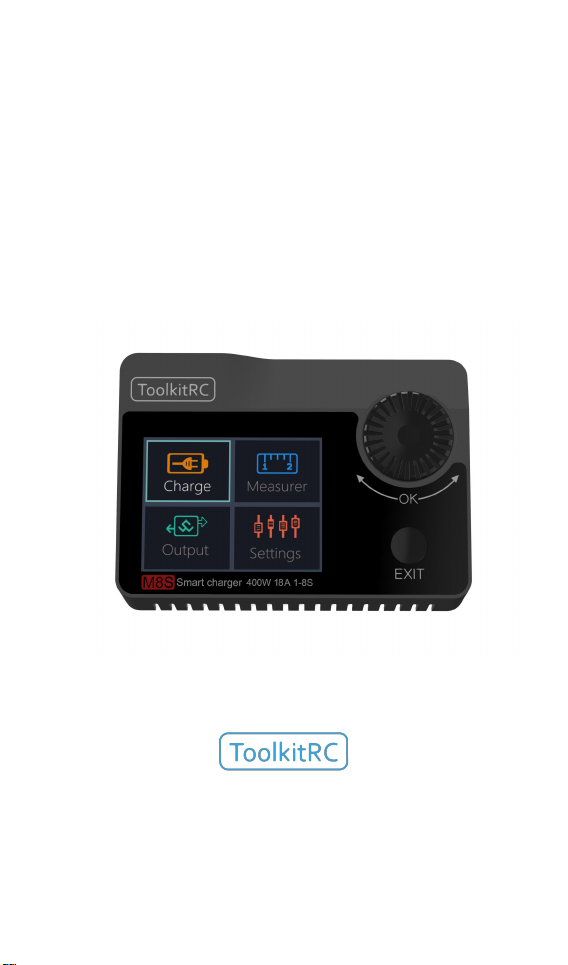
M8S
Manual V1.3
2020.06
www.ToolkitRC.com
ToolkitRC Technology (Shenzhen) Co.. Ltd.
@
ToolkitRC
2019
Page 2

2
Introduction
Tips
Important
Information
Please read this manual carefully before use.
Key Points
Further information
product please scan the QR code below to stay up to date
with news. information and firmware updates for your
charger.
Thank you for purchasing the M8S Toolkit Charger.
To ensure you have the best experience with this
@
ToolkitRC
2019
Page 3

3
Safety
1. The M8Scharger allows input from 7-30V. For best
operation ensure the power supply is stable and pay
attention to connection polarity.
2. Do not use this product in excessively hot, wet or
moist conditions or near flammable objects, liquids
or gas.
3. Only use this product while under supervision, do
not leave charging batteries unattended.
4. Disconnect batteries or power supply when not in
use.
5. When charging please select the charge voltage
and current suitable to your battery. Check the
battery manufacturers specifications for further
details. Do not charge batteries above their rated
voltage and amperage specifications.
@
ToolkitRC
2019
Page 4

4
Contents
Introduction
....................................................2
Key Points ....................................................... 2
Safety............................................................... 3
M8SLayout......................................................7
Quick start .......................................................8
Charge and discharge
1. Battery type setting
2. Cutoff voltage setting(TVC)
................................ 10
................................. 10
............. 12
3. NiMH Setting(PeakV) ........................ 13
4. Battery Setting .........................................14
5. Current setting .........................................15
6. Working mode ........................................ 17
Battery Measurement
................................. 26
ESC Wattmeter
Signal output
............................................ 29
................................................31
Power output ............................................... 34
@
ToolkitRC
2019
Page 5

5
Drone charging ............................................36
System settings ............................................ 38
Other functions
Specification
................................................. 43
............................................41
@
ToolkitRC
2019
Page 6

6
Product description
M8Sis a multi-function charger and discharger
that integrates receiver and servo test functions
along with power supply functions.
•Lipo. LiHV. LiFe Lion1-8S. NiMh 1-20s. PB 1-12s
battery charging and discharging and balance
management
•Charging current: Maximum 18A @400W
•Discharge Current: Recovery MAX 18A@400W
normal mode MAX 5A @20W
•Lithium battery full voltage can
be set (TVC)
• can measure battery voltage.
battery internal resistance. lithium battery balance
management
•ESC power meter 400W@18A, simultaneous output
voltage and throttle signal.
•Measurement of signal values such as PWM/PPM/
SBUS with accuracy of up to 1us
• can output PWM/PPM/SBUS standard signal.
accuracy up to 1 microseconds
• constant current constant voltage source output.
can customize 1-30V constant voltage. 1-18A
constant current
• can be adapted to the mainstream UAV battery.
automatically activated and charged.
• USB [email protected] output. rechargeable mobile
device.
•Device simulation for USB flash drive. copy upgrade
file to achieve product firmware upgrade
@
ToolkitRC
2019
Page 7
7
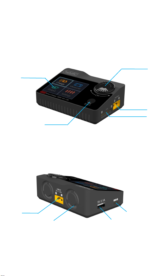
M8SLayout
Display
Exit
Output
Balance Port
Input
Cooling
USB port
Signal Port
Knob wheel
Front
@
ToolkitRC
2019
Page 8
8
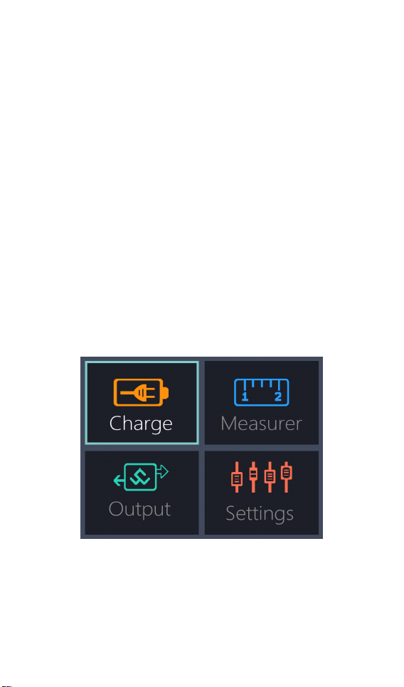
Back
Quick start
1. The 7-30V power supply is connected to the
input port on the back of the M8S
2. The display shows the bootup logo and stays
for 2 seconds
3. Accompanied with do-re-mi bootup sound
4. the bootup is completed. the display enters
into the main interface as shown below
5. Rotate the [knob]. move the cursor to select
function. press the [OK] button to enter the
selected function and enter the
corresponding interface
@
ToolkitRC
2019
Page 9

9
6. After entering the related function interface.
1. Short press the [OK] once to determine
the key function.
Rotate the [knob] to move the cursor to
select the setting item or value. press the [OK]
and modify the option or value. After the
modification is completed. press the [OK] to
confirm.
7. Press the [Exit] key to end the modification or
return to the previous screen.
===============================
2. Press and hold the [OK] for 2 seconds as the
delete key function.
3.Pressing any button will give a sound prompt.
===============================
@
ToolkitRC
2019
Page 10
10
Charge and discharge
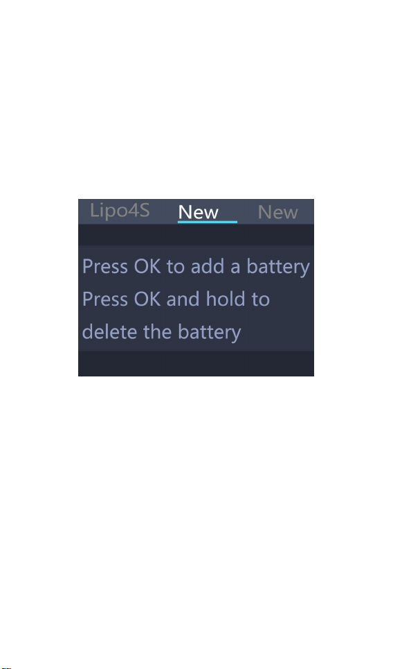
After selecting the [Charge] function on the main
interface press [OK] to enter the charging function.
The following interface is displayed.
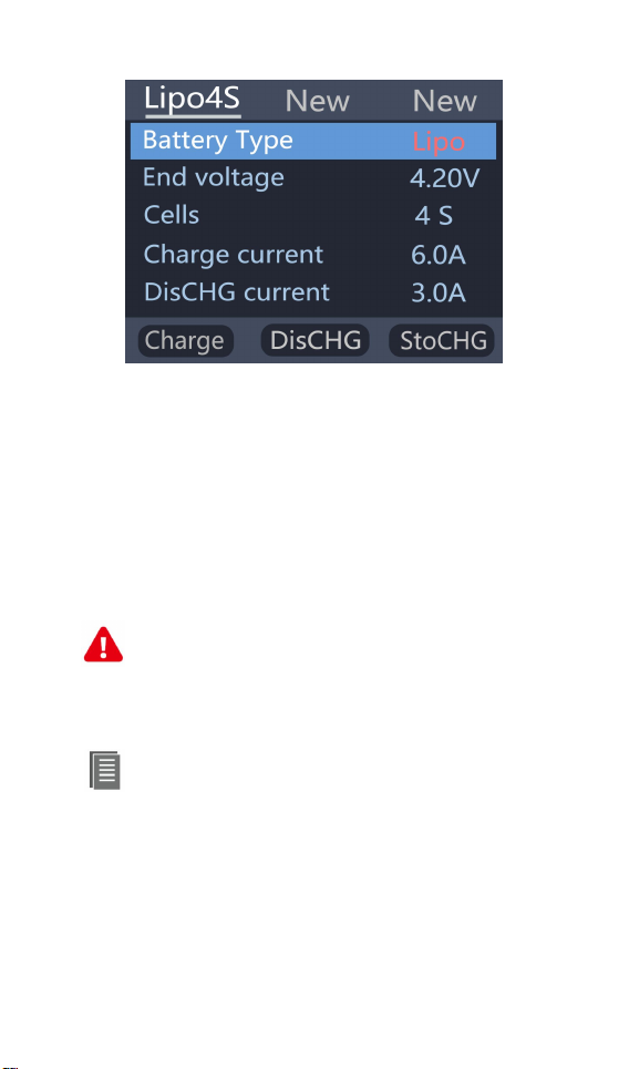
1. Battery type setting
Rotate the [knob] to move the cursor. Select the
battery type to be set. Press [OK] to enter the
battery setting interface as shown below.
@
ToolkitRC
2019
Page 11
11
Move the cursor to [Lipo] and press [OK] to modify
Important:
1. Incorrect battery type charging may
damage the battery. charger. and may lead
2. battery that cannot be indicated the
battery type. pls do not use this product to
the battery type. The charger supports charging and
discharging five types of batteries: Lipo. LiHV. LiFe.
Lion.NiMh. PB. After selecting the correct battery
that matches the actual battery Short press [OK] and
[Exit] Effective.
===============================
risk of burning. etc.. please be double careful.
charge
===============================
Information:
1. Lipo: often referred to as lithium polymer
battery. nominal voltage 3.70V. fully charged
@
ToolkitRC
2019
Page 12
12
4.20V battery
2. LiHV: often referred to as high-voltage lithium
battery. nominal voltage 3.85V. 4.35V battery
after full
3. LiFe: often referred to as lithium-iron Phosphate
battery. nominal voltage 3.30V. fully charged
3.60V battery
4. Li-ion: often referred to as lithium-ion battery.
nominal voltage 3.60V. fully charged 4.10V battery
5. NiMh: Often called nickel-metal hydride battery.
nominal voltage 1.20V
6. PB: often referred to as lead-acid battery. nominal
voltage 2.00V
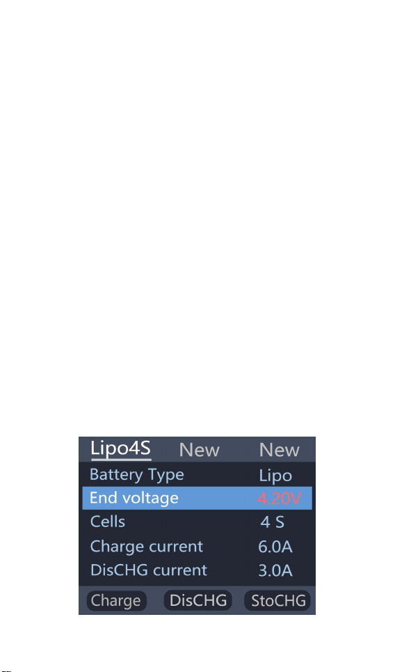
2. Cutoff voltage setting(TVC)
Move the cursor to [End Voltage] and press [OK] to
modify the battery charge cut-off voltage. Rotate
the [knob] to adjust the value and step 10mV.
@
ToolkitRC
2019
Page 13
13
===============================
1. only LiPo. LiHV. LiFe.Lion battery can set
the cutoff voltage
Tips:
1. Only NiMh battery can set the battery
2. Do not modify the cutoff voltage when you are
unfamiliar with battery characteristics.
3. the cutoff voltage can be set to the range of
positive and negative 50mV of full voltage
4. vocabulary explanation: TVC: terminal voltage
control
===============================
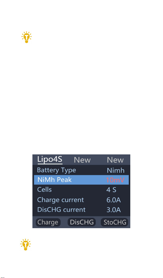
3. NiMH Setting(PeakV)
When the battery type is NiMh. you can set the
negative voltage value when the battery is full. and
the range can be set from 5mV to 20mV. as shown
below.
===============================
@
ToolkitRC
2019
Page 14
14
negative voltage value
Tip:1. the battery which was over- discharged
or over-charged. may cause the number of
2. vocabulary explanation:PeakV: Peak voltage drop
per piece when NiMH battery is full
===============================
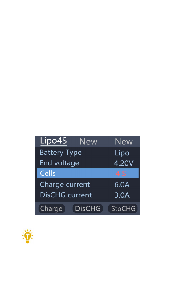
4. Battery Setting
Move the cursor to the [Cells] and press the [OK]
button to change the number of battery cells. Rotate
the [knob] to adjust the value. When set to [Auto].
the charger will automatically recognize the number
of cells on the connected batteries according to the
voltage of battery which connected with output port
=================================
cells to be recognize falsely. you need to manually
set the correct number of cells.
@
ToolkitRC
2019
Page 15
15
2. If the number of cells was set incorrectly. The
battery cannot be full charged. or be overcharged
and damaged. please set it carefully.
After the Lixx battery is connected to the
balance port. the number of battery cells can be
more accurately identified.
===============================
5. Current setting
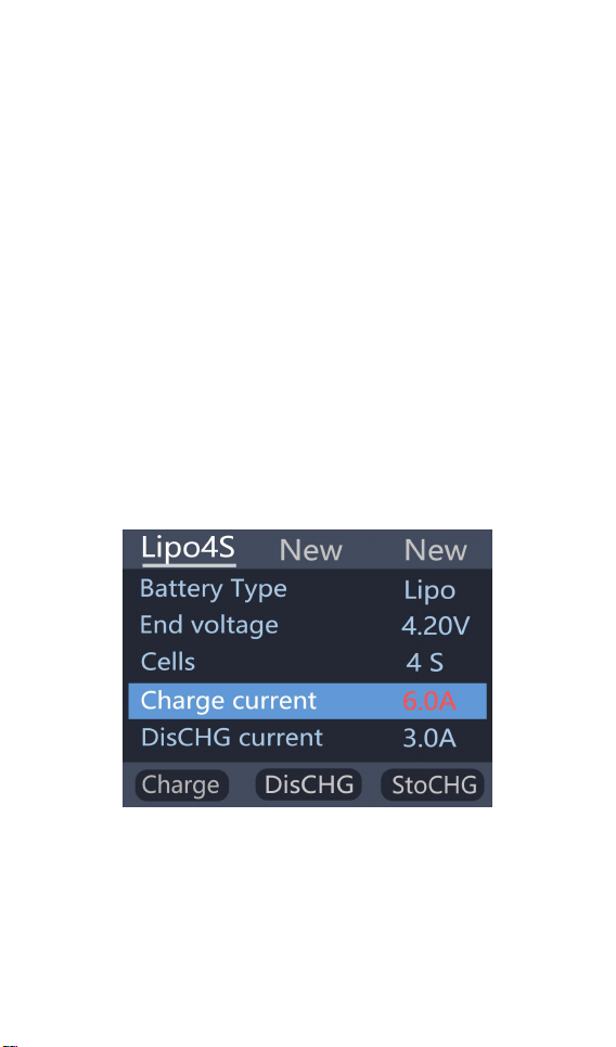
Move the cursor to the charging current
[Charge Current] position and press [OK] to modify
the charging current. Rotate the [knob] to adjust the
value and step 0.1A. Press and hold [knob] to add or
subtract quickly. The charger supports up to 18.0A.
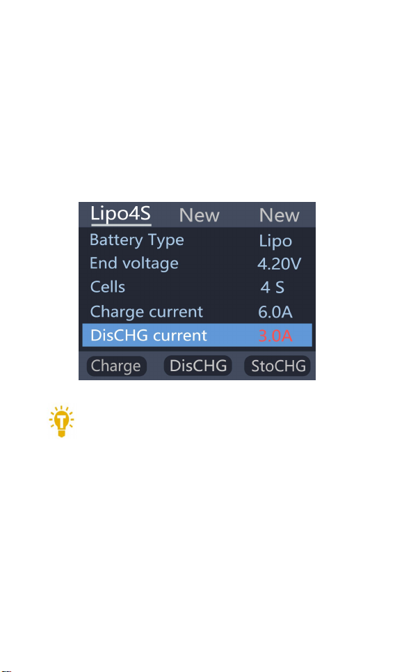
Move the cursor to the [Discharge current]
position and press [OK] to modify the discharge
current. Press up or down to adjust the value and
step 0.1A. Press and hold up or down can be quickly
@
ToolkitRC
2019
Page 16
16
reduced. The charger supports two discharge
Tip:
1. Please set the charging rate at 1-2C
modes. 1. ordinary discharge mode. through internal
heat dissipation discharge. maximum support
2.0A@8W. 2. Recovery discharge mode. When the
input power source is a battery this function can
recycle electrical energy to the input battery, the
maximum support 10.0A current.
===============================
according to the battery capacity. For example. if the
battery capacity is 2000mAh. please set the charging
current to 2.0-4.0A.
2. charging and discharging current is only valid in
the corresponding working mode.
3. For the discharge mode setting. refer to the
<System Settings> chapter of this manual.
===============================
@
ToolkitRC
2019
Page 17
17
6. Working mode
Tip: 1,To use energy recovery discharge mode
(recycle) please read the details on setting
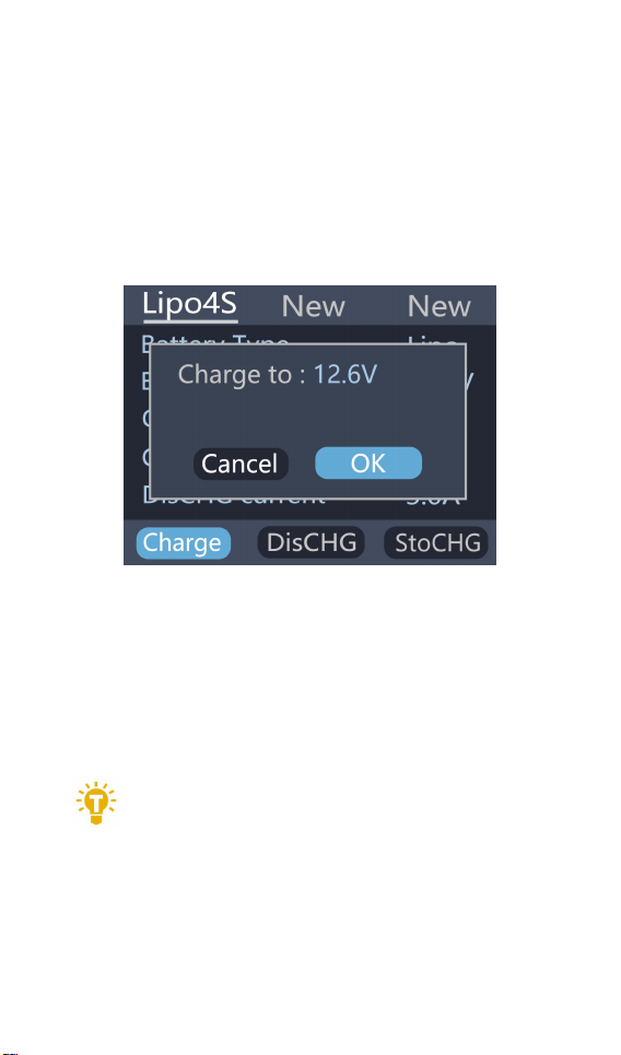
Move the cursor to [Charge] [DisCHG] [StoCHG]
position. press [OK]. the charger will work in the
mode of the selected function. When selected as
[Charge]. it will indicate the target voltage that will
charge the battery. As shown below
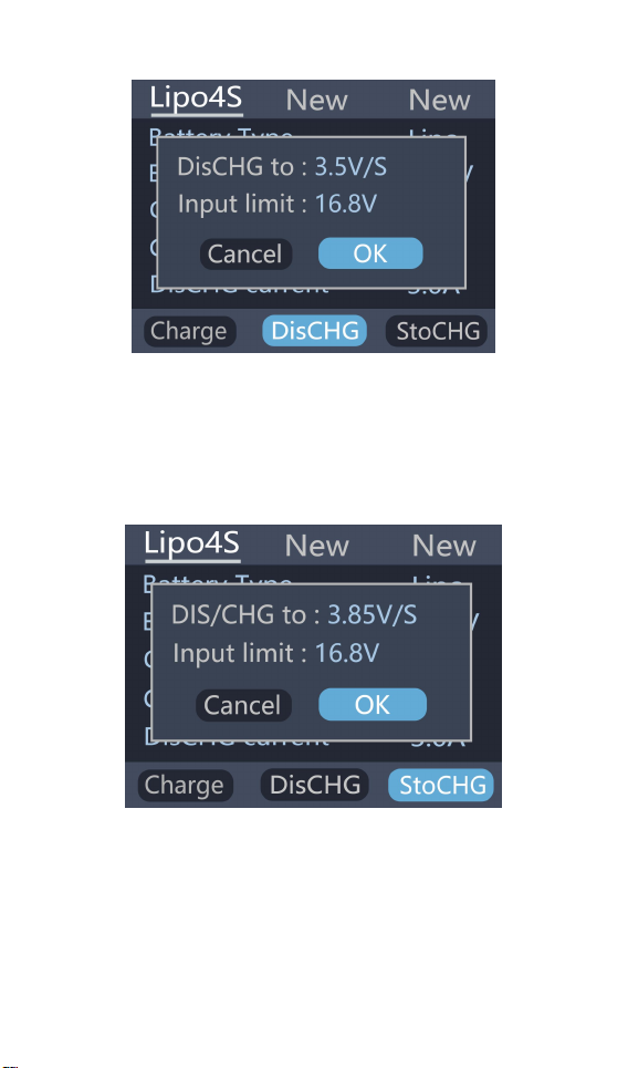
When selected as [DisCHG]. it will prompt the target
voltage to discharge the battery to. If the discharge
mode is to recycle the discharge. it is also necessary
to set the cutoff voltage of the battery being used as
the power source. As shown
=================================
discharge mode on page 37 of this manual.
=================================
@
ToolkitRC
2019
Page 18
18
When selected as [StoCHG]. it will prompt the target
voltage to charge and discharge the battery. If the
discharge mode is to recycle the discharge to the
power source batter. it is also necessary to set the
cutoff voltage of the battery. As shown below
The high limit voltage of recovered. The default is
0.5V higher than the input voltage. Please set
according to the maximum limit voltage of the input
power supply. To cancel the operation. move the
cursor [Cancel] or press [Exit]. Move the cursor to
@
ToolkitRC
2019
Page 19

19
[OK]. short press [OK] to start charging. and display
Tip:The discharge cutoff voltage should be
set.
the charging and discharging work interface.
=================================
1. According to the discharge characteristics of the
battery.
2. After the recovery limit voltage is set to the
highest protection voltage of the power supply.
the charger will automatically stop the recovery
discharge. Setting a high overvoltage may
damage the input power. Do not set the input
limit higher than the capacity of the power
source battery.
===============================
@
ToolkitRC
2019
Page 20
20
Charge and discharge
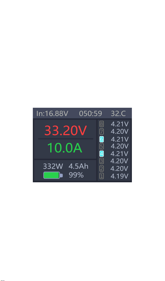
When charging and discharging starts the charger
enters the working interface as shown below.
Rotate the [knob] key on this screen to switch the
bottom status display information or press and hold
[OK] for 2 seconds to dynamically set the working
current. As shown below
@
ToolkitRC
2019
Page 21
21
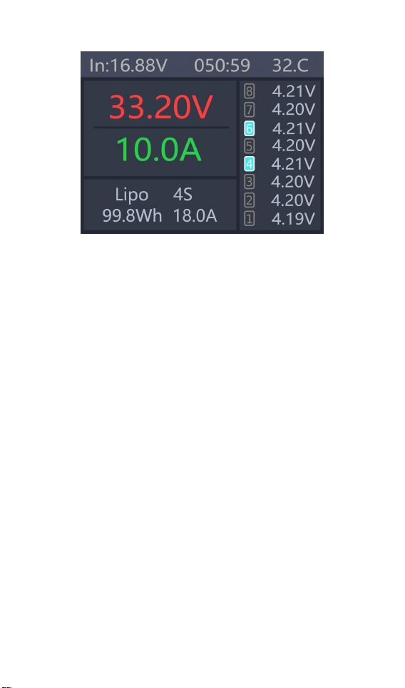
33.20V: The battery voltage of the output port.
10.0A: Charging or discharging current
Current limit flag. P: power. C: maximum current
I: input over current or Power A: activate charging
F: The main port is full voltage or a single cell is full
332W: Charge or discharge power of the charger
32'C: internal temperature of the charger
050:59: The time when the work has started. Unit:
minute: second
4.5Ah: the capacity that has been charged and
discharged this time
Lipo 4S: currently set battery type and number of
cells
18.0A: Current operating current set. Long press to
modify.
IN 16.88V: Input supply voltage
99.8Wh: Input power that has been discharged from
the power supply.
1 4.19V: 1st battery voltage
@
ToolkitRC
2019
Page 22
22
2 4.20V: 2nd battery voltage
Tip:1. Only charge or discharge batteries under
supervision do not leave them unattended.
3 4.20V: 3rd battery voltage
4 4.21V: 4th battery voltage (balancing)
5 4.20V: 5th battery voltage
6 4.21V: 6th battery voltage (balancing)
7 4.20V: 7th battery voltage
8 4.21V: 8th battery voltage
-.--V : no battery connected
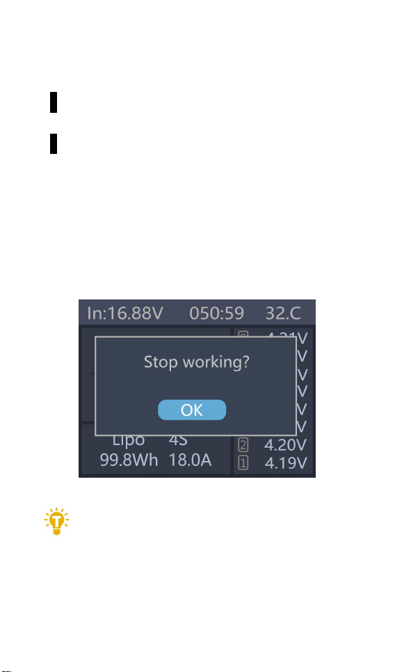
To end the charge and discharge work. short press
[Exit]. in the pop-up prompt box. select [OK] to exit.
When charging is complete or charging is wrong
A pop-up windows display and a tone sounds.
===============================
2. When charging and discharging the lithium
battery if only connect with the main port of battery
it will not be balanced. Please pay attention to the
balance of the battery. Connect the battery with
@
ToolkitRC
2019
Page 23
23
balance port so the balance management is
automatically performed.
3. When charging is completed unplug the battery.
After accessing the new battery. it will automatically
continue to charge and discharge according to the
setting mode. When set to a fixed number of cells.
you need to access the same number of batteries.
When setting to automatically detect the number of
battery cells. please pay attention to whether the
number of detected cells matches the actual ones.
===============================
Signal measurement
After selecting the [Measurer] function on the
main interface. press [OK] to enter the function and
display the following interface. Press up or down to
select the type of signal to be tested.
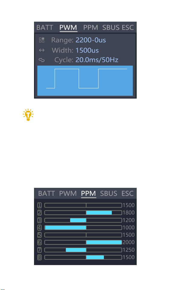
Move the cursor to the [PWM] item. press [OK] to
enter the PWM test interface as shown below.
@
ToolkitRC
2019
Page 24
24
===============================
Tip:
1. PWM and PPM signals can automatically
identify and switch to the corresponding interface.
2. sBus is an inverted signal. baud rate 100kbps 8-bit
data bit 2-bit stop bit even parity
===============================
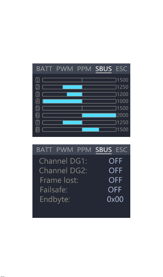
Press up or down switch on the measurement main
interface to move the cursor to the [PPM] item. press
[OK] to enter the PPM test interface as shown below.
@
ToolkitRC
2019
Page 25
25
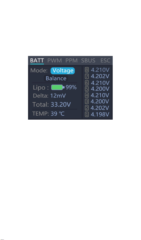
Move the cursor to the [SBUS] item and press [OK]
to enter the compatible signal test of SBus. Dbus.
etc.. Press up or down and switch the 16 channel
value and status bit. The display interface is as
follows 2 (9-16 channel display is omitted)
@
ToolkitRC
2019
Page 26

26
@
ToolkitRC
2019
Page 27
27
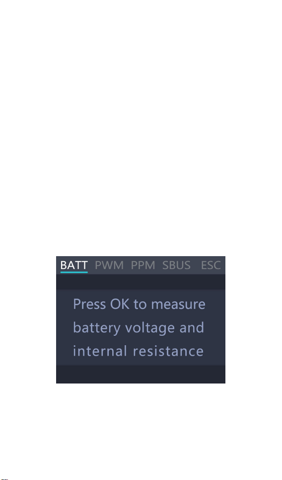
Battery Measurement
After selecting [Measurer] function in the main
interface of measurement press [OK] to enter the
function and display the following interface.
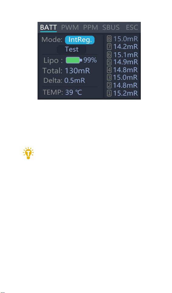
This interface displays the current battery voltage
value and range Move the cursor select [Balance]
and press [OK] to start balancing management of
the batteries. Move the cursor to the [Voltage]
position press [OK] to switch to internal resistance
mode and display the following figure.
@
ToolkitRC
2019
Page 28
28
Move the cursor to [Test] press [OK] once to start
Tips:
1. This testing needs to charge the battery
testing the internal resistance. The testing is finished
after about 5 seconds and shows the internal
resistance of the battery
===============================
for 5A current for a short time. please ensure that
the input power is sufficient and the battery is not
overcharged.
===============================
@
ToolkitRC
2019
Page 29
29
ESC Wattmeter
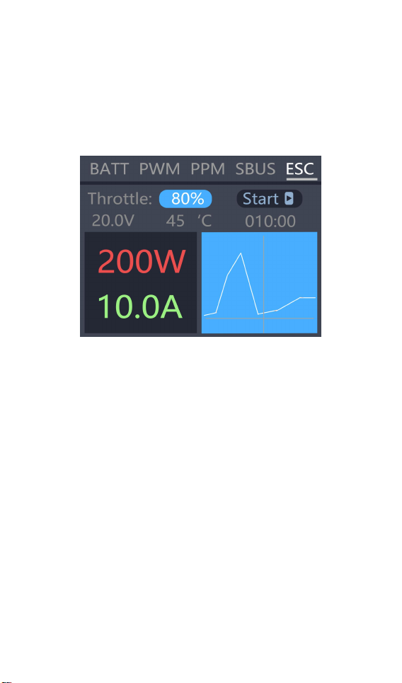
After selecting [ESC] function in the main interface of
measurement, press [OK] to enter the function and
display the following interface.
Display instructions:
Throttle signal 80% : PWM signal value to be output
from the signal
Output 20.0V: Input voltage value, straight output
from the main port
Start: After pressing the OK button, the output signal
and the main port voltage are started.
200W: The power being output
10.0A: Current being output
010:00: Working time
45°C: current internal temperature of the device
@
ToolkitRC
2019
Page 30

30
=================================
Tips:
1, please do not connect the battery in this
mode, otherwise it may damage the device
2. Please adjust the throttle value slowly during
the test to prevent the current from being too large.
=================================
@
ToolkitRC
2019
Page 31

31
Signal output
After selecting the [Output] function on the main
interface press [OK] to enter the function. and the
following interface is displayed.
Rotate the [knob] to move the cursor to the [PWM]
item press [OK] to enter the PWM test interface as
shown below.
Move the cursor to the [Manual] item press [OK] to
set the output mode. which can be set to Manual.
@
ToolkitRC
2019
Page 32
32
Auto 1. Auto 2. Auto 3.
When the mode is set to manual. you can move the
cursor to the pulse width and period items to set the
signal value to be output.
When set to Auto 1. 2. 3. the pulse width value of the
output PWM will automatically change at 3 different
speeds.
Pulse width can be set from 800 to 2200us The cycle
can be set from 2.5ms (400Hz) to 50.0ms (20Hz).
Rotate the [knob] on the output main interface to
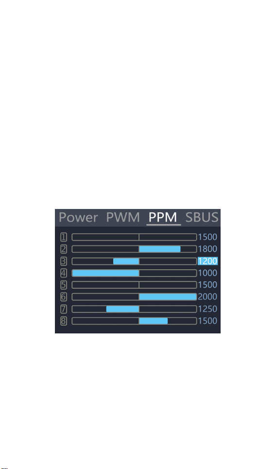
move the cursor to the [PPM] item. press [OK] to
enter the PPM output interface as shown below.
Rotate the [knob] to move the cursor to the
value that needs to be modified. Press [OK] to
modify the output pulse width value of this channel.
Press up or down under the output main interface to
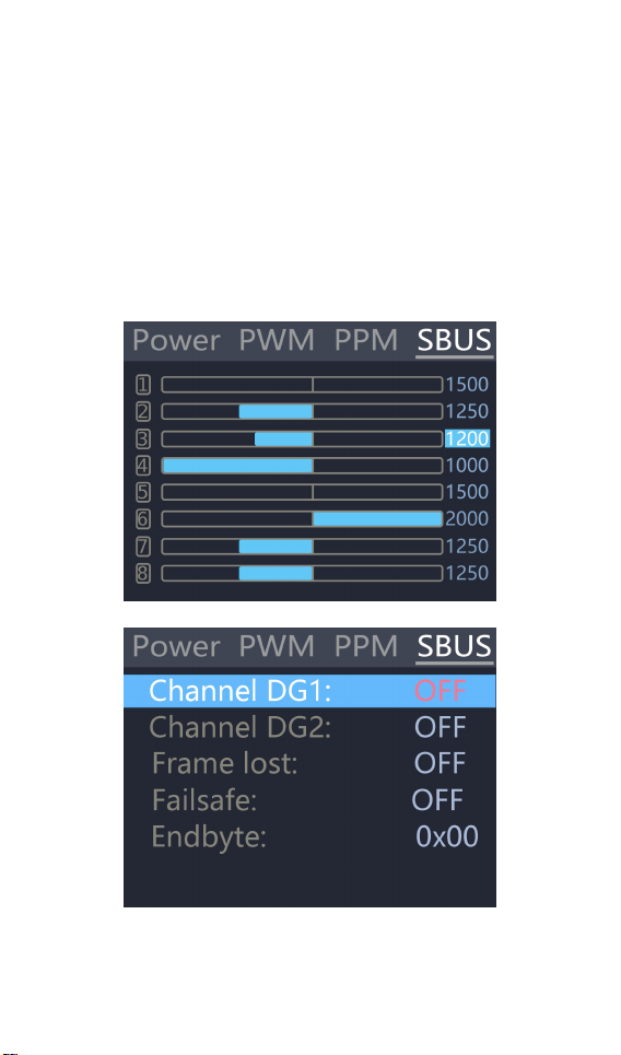
move the cursor to the [SBUS] item. press [OK] to
enter the compatible signal output of SBus. Dbus.
@
ToolkitRC
2019
Page 33
33
etc.. Press up or down. and switch the 16 channel
value and status bit. The display interface is as
shown below (9-16 channel and status display
interface diagram omitted) Rotate the [knob] to
move the cursor to the value of the channel to be
modified. Press [OK] to modify the output pulse
width value of this channel.
@
ToolkitRC
2019
Page 34
34
Power output
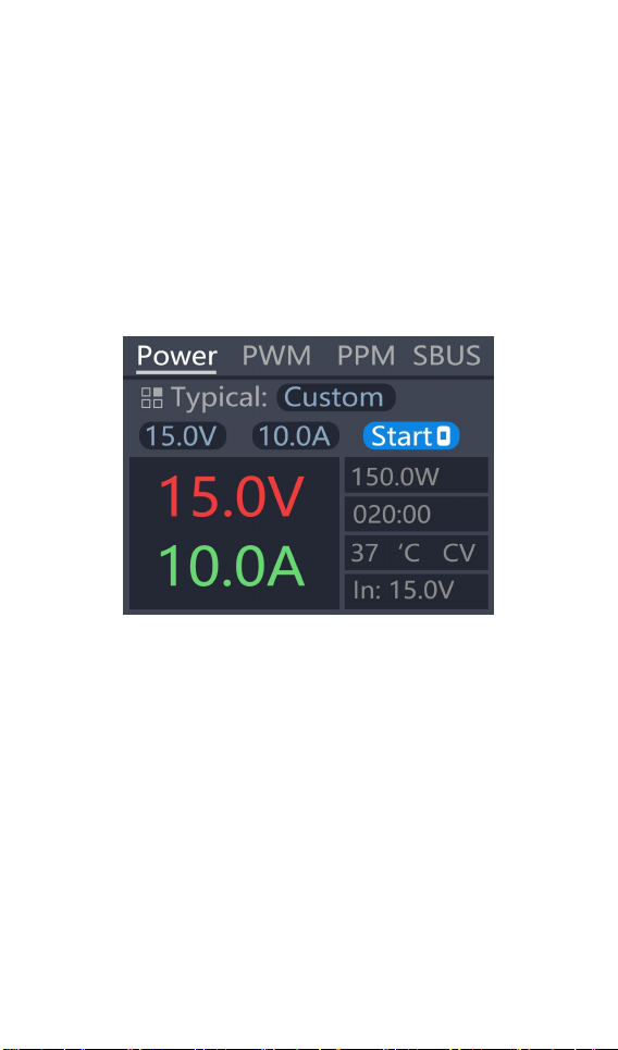
Rotate the [knob] on the [Output] main interface to
move the cursor to the [Power] item. press [OK] to
enter the power output function. This product will
output the input power according to the setting
voltage and current. constant voltage and constant
current. The display interface is as shown below
Typical value: It is a common typical output
mode. which can be set into the following 3
modes.
1. Input pass-through: Do not achieve constant
current and constant voltage. and output the input
voltage directly from the output main port.
2. custom: users can manually set the value of
voltage and current limit according to demand
3. commonly used drone battery charging: select
@
ToolkitRC
2019
Page 35

35
the corresponding battery. automatically configure
Important:
1. Do not charge the normal battery when the
the relevant output voltage and current.
Configure the relevant output voltage and current
12.0V: The voltage output from the output main port
can be set to 5-30V.
10.0V: Maximum current limit output from the main
port. the range of 1-15A can be set.
Start: Start output. stop output button
0.0V 0.0A 0.0W: Current output current and power
of the main port.
33 ° C: current internal temperature of the device.
00:00:output time
CV CC: current working mode. CV: constant voltage
CC: constant current
===============================
power output is turned on. Otherwise. the battery
may be damaged or the device may be damaged.
===============================
@
ToolkitRC
2019
Page 36
36
Drone charging
Rotate the [knob] on the [Output] main interface
to move the cursor to the [Power] item. press [OK] to
enter. then move the cursor to the typical value and
change the output mode to the model of the drone
that needs to be charged. Move the cursor to [Start]
and press the enter key. The charger will output the
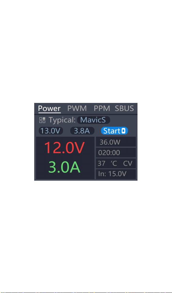
set voltage. The display interface is as shown below
Typical: For common drone models. it can be set to
the following four types of drones. Mavic2. Mavic.
Phantom. Inspire.
13.0V: The voltage value when the current battery is
full cannot be changed.
3.8AV: Maximum current for charging. adjustable
current.
Start: Start output. stop output button
12.0V 3.0A 36.0W: Voltage. current and power
@
ToolkitRC
2019
Page 37

37
output from the main port.
Tip:
1. There is no need to open the battery
Important:
1. Do not charge the normal battery in this
working mode. otherwise the battery may be
20:00 Working hours
In: 15.0V: Input voltage.
37 °C: Current internal temperature of the device.
CV CC: Working mode. CV: constant voltage CC:
constant current
===============================
before charging. Automatic activation and charging
===============================
damaged or the device may be damaged.
===============================
@
ToolkitRC
2019
Page 38
38
System settings
After selecting the [Settings] function on the main
interface. press the [OK] key to enter the function
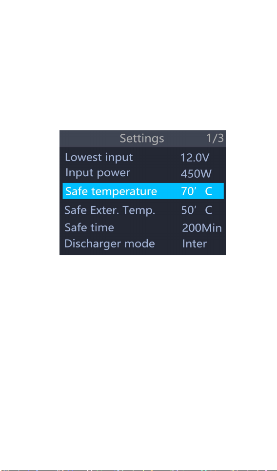
display the following interface. Rotate the [knob] to
switch to the second interface. as shown below
Function Description:
Minimum input voltage: Below this voltage. the
device will stop the main port output.
Maximum input power: The maximum power
obtained from the input port during charging.
Safe operating temperature: above this temperature
value. the device will stop the main port output
Safe Exter. Temp.: External temperature sensor above
this temperature value. the device will stop the main
port output
Safe charging time: The maximum time for
continuous charging and discharging. will stop
working if it exceeds
@
ToolkitRC
2019
Page 39
39
Discharge mode: Can be set to normal discharge.
discharged by internal heat dissipation. Or recycle
the discharge and recycle the energy to the input
power source (the input must be rechargeable
battery power) , Or external mode(need connect
load into the input port)
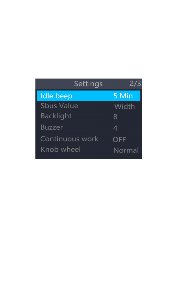
Idle beep:If the device is not operated during
this time, the sound and light will be
disconnected from the power supply.
SBUS value: The display mode of sBus when
measuring or outputting. can be set to pulse width
value (1000-2000). or original value (0-2047).
Backlight: The brightness level of the backlight of the
display can be set to 1-10
Buzzer: The tone of the buzzer can be set to off.
Energy saving tips: The sound and light are not
disconnected from the power supply during this
time.
@
ToolkitRC
2019
Page 40
40
Continuous work: After charging and discharging.
whether to continue charging and discharging after
replacing the battery
Work completed: When the charging is completed,
you can set the end or charge with a small current.
Knob wheel: Adjust the sensitivity of the knob wheel
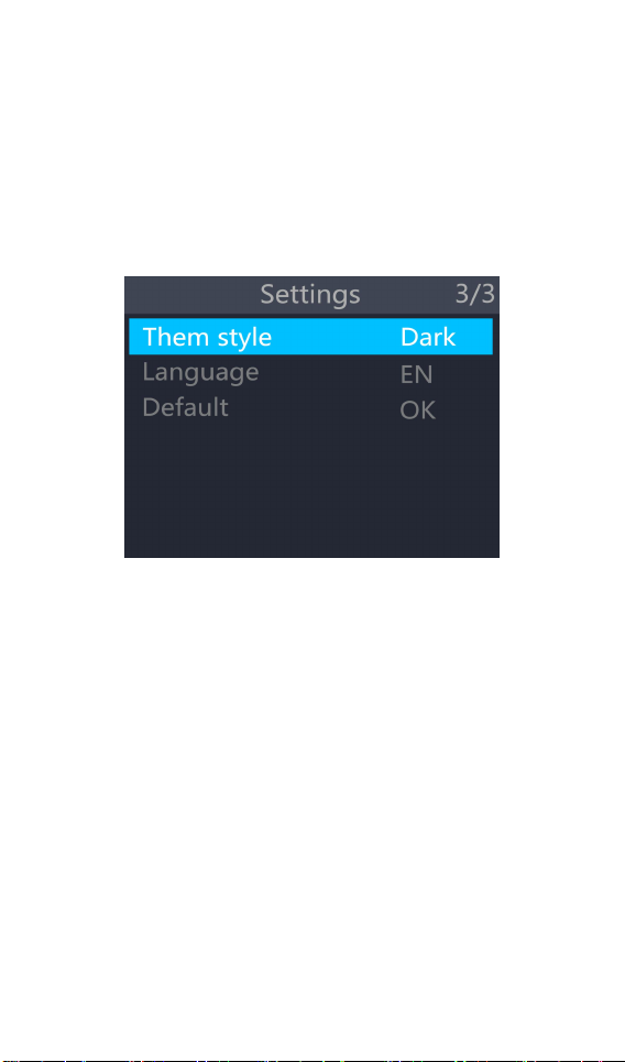
Them style: The color style displayed by the system
interface.
Language: The system displays the language.
Choose from English, German, French, Italian,
Portuguese, Chinese, and more.
Default : Restore all settings to their default values.
@
ToolkitRC
2019
Page 41

41
Other functions
1. Firmware upgrade
After connecting the M8S to the computer via the
USB cable in the box. the computer will recognize
the USB flash drive named Toolkit. Download the
upgrade file app.upg on the official website to
overwrite the files in the USB flash drive to upgrade
the firmware.
2. USB 5.0V output
In addition to the above upgrade functions. the USB
interface can also output 2.1A current to charge
mobile devices.
3. energy saving reminder
When the M8S is idle for 5 minutes. the backlight will
automatically decrease.
4. Automatically continue to charge and discharge
after the next one .
unplug the battery for 2 seconds. then access the
next battery. the device will automatically continue
to charge and discharge.
5. Fan rating
When the internal temperature of the device reaches
40 ° C. the fan work at the half-speed air volume to
reduce noise. When the internal temperature
reaches 50 ° C. the fan turns on the full speed air
volume to enhance heat dissipation.
@
ToolkitRC
2019
Page 42

42
6. Manually calibrate the voltage.
Press and hold the Jog Wheel while powering up th
e charger. The system will enter the manual
calibration voltage function. Use a voltmeter to
measure the actual voltage of each battery. move
the cursor to the corresponding voltage value. and
modify the voltage value to match the voltmeter
value for calibration. After the calibration is
completed. move the cursor to save. short press
once. the buzzer sounds once and the save is
successful. Exit or Turn off device
7. Supplement
When the lithium battery is fully charged. the
prompt "fast charging has ended" .If the battery is
not removed. constant voltage trickle charging will
be performed automatically to bring the battery to
the even more full state.
8. Extern discharge
Connect the battery to the output and the load
resistor to the input. Set the discharge mode to
external discharge in the setup menu. Set the cutoff
voltage and load power, the device will use an
external resistor to discharge the battery, and
balance management.
@
ToolkitRC
2019
Page 43

43
Specification
Charging
Input
7-30V@MAX18A
Battery Type
LiPo LiHV LiFe Lion@1-8S
NiMh @1-20S Pb @1-12S
Bal Cur.
800mA @2-8S
Accuracy
±0.01V
Charging
Power
0.1-18A@400W
Discharging
Power
0.1-18A@400W Recycle Mode
0.1-3A@15W Normal Mode
USB
upgrade
Measuring
PWM
880us-2200us @20-400Hz
PPM
880us-2200us*8Ch @20-50hz
SBUS
880us-2200us*16ch @20-100Hz
Voltage
1.0V-5.0V @1-8S
IR
1-100mR @1-8S
Output
PWM
500us-2500us @20-1000Hz
PPM
880us-2200us*8ch @50hz
SBUS
880us-2200us*16ch @74Hz
Power
1-18A@1-30V Mode: CC+CV
Display
LCD
TFT 2.4 inch 320*240 resolution
Product
Size
98mm*68mm*35mm
Weight
170g
Individual
packing
Size
108.5mm*80.5mm*46mm
Weight
255g
@
ToolkitRC
2019
 Loading...