


OPERATOR MANUAL
AUTO LENSMETER
TL-3000A
TL-3000A
•Read this Operator Manual carefully before using this instrument in order to operate it properly and safely.
•Do not use procedures other than those specified in this manual.
•Keep this Operator Manual handy when operating this instrument.
•For any questions about this instrument or about this manual, contact your Tomey representative or local distributor.
IMPORTANT PRECAUTION
• Never install this instrument near locations where explosive or flammable materials are used or stored. Such installation may result in a fire or an explosion.
SYMBOLS USED IN THIS MANUAL
The symbols used in this manual represent the following messages:
•This is a precaution that, if unheeded, will result in a hazardous situation where there is an imminent danger of serious injury or
death.
• This is a precaution that, if unheeded, may result in a situation where there is a possibility of minor or moderate injury or damage to property.
• This is an additional instruction, which may contain a special precaution on company policy related , either directly or indirectly, to the safety of personnel or to the protection of property.
i
IMPORTANT PRECAUTION / SYMBOLS USED IN THIS MANUAL

Authorized Tomey Service Centers:
Headquarters, Pacific rim
Tomey Corporation (Tomey Japan)
2-11-33 Noritakeshinmachi
Nishi-ku, Nagoya 451-0051 JAPAN
Tel: +81 52-581-5327
Fax: +81 52-561-4735
North/South America
Tomey Corporation USA (Tomey USA)
300 Second Ave.
Waltham, MA 02451 USA
Tel: +1 781-890-1515
Fax: +1 781-290-5885
Europe
Tomey AG (Tomey Europe)
Am Weichselgarten 19a
91058 Erlangen-Tennenlohe GERMANY
Tel: +49 9131-77710
Fax: +49 9131-777120

ID: 0110

CONTENTS
1. PRIOR TO USE ....................................................... |
1-1 |
|
1.1 |
Cautionary notes ................................................................ |
1-1 |
1.2 |
Unpacking .......................................................................... |
1-3 |
1.3 |
Explanation of terms ........................................................... |
1-4 |
1.4 |
Outline of operation ............................................................ |
1-6 |
2. COMPONENT LIST AND FUNCTIONS .................. |
2-1 |
|
2.1 |
Front ................................................................................... |
2-1 |
2.2 |
Back ................................................................................... |
2-2 |
2.3 |
Screen layout ..................................................................... |
2-3 |
2.4 |
Buttons for operations ........................................................ |
2-4 |
3. METHOD OF OPERATION ..................................... |
3-1 |
||
3.1 |
Preparation for operating .................................................... |
3-1 |
|
3.2 |
Measuring methods ............................................................ |
3-3 |
|
3.2.1 Measuring single vision lenses ........................................ |
3-3 |
||
|
|
a) Measuring single lenses (S mode)............................... |
3-3 |
|
|
b) Measuring framed lenses (RL mode)........................... |
3-6 |
3.2.2 |
Measuring multi-focal lenses .......................................... |
3-10 |
|
|
|
a) Measuring progressive addition lenses |
|
|
|
(PROG mode) .................... |
3-11 |
|
|
b) Measuring bifocal and trifocal lenses ......................... |
3-15 |
3.2.3 |
Measuring Lens Interpupilling ........................................ |
3-18 |
|
|
|
a) Center to Bottom Display ........................................... |
3-24 |
3.2.4 |
Measuring prism ............................................................. |
3-26 |
|
3.2.5 Measuring high index lenses (HI mode)......................... |
3-30 |
||
3.2.6 Measuring High Power lenses (HP mode) ..................... |
3-31 |
||
3.2.7 Measuring contact lenses (CL mode) ............................ |
3-32 |
||
3.2.8 |
Auto hold mode .............................................................. |
3-36 |
|
3.2.9 |
Detecting progressive lenses ......................................... |
3-37 |
|
3.2.10 UV checking function ..................................................... |
3-38 |
||
3.3 |
Operating the clamp, marking device and lens table ....... |
3-42 |
|
3.3.1 |
Clamp ............................................................................. |
3-42 |
|
3.3.2 |
Marking device ............................................................... |
3-43 |
|
3.3.3 |
Lens table....................................................................... |
3-44 |
|
3.4 |
Setup ................................................................................ |
3-45 |
|
3.5 |
Printout ............................................................................. |
3-56 |
|
3.6 |
Data communication (RS-232C) ...................................... |
3-57 |
|
3.7 |
LCD contrast adjustment .................................................. |
3-58 |
|
3.8 |
AUTO POWER OFF (Automatic power saving function) .3-59 |
||
CONTENTS ii

4. MAINTENANCE AND INSPECTION ....................... |
4-1 |
||
4.1 |
Warranty ............................................................................. |
4-1 |
|
4.2 |
Routine maintenance ......................................................... |
4-2 |
|
4.2.1 |
Cleaning cover glass ........................................................ |
4-2 |
|
4.3 |
Replacing spare parts ........................................................ |
4-3 |
|
4.3.1 |
Fuse ................................................................................. |
4-3 |
|
4.3.2 |
Ink cartridge ..................................................................... |
4-4 |
|
4.3.3 |
Printer paper .................................................................... |
4-6 |
|
4.4 |
Storage ............................................................................... |
4-7 |
|
4.5 |
Packing materials ............................................................... |
4-7 |
|
5. |
TROUBLESHOOTING ............................................. |
5-1 |
|
|
5.1 |
Troubleshooting guide ........................................................ |
5-1 |
|
5.1.1 General operation .............................................................. |
5-1 |
|
|
5.1.2 Progressive addition lens measurement ............................ |
5-4 |
|
|
5.2 |
Error messages .................................................................. |
5-8 |
6. |
SPARE PARTS ........................................................ |
6-1 |
|
7. |
SPECIFICATIONS ................................................... |
7-1 |
|
|
7.1 |
Measurement ..................................................................... |
7-1 |
|
7.2 |
Data control ........................................................................ |
7-1 |
|
7.3 |
Physical dimensions and electrical requirements ............... |
7-2 |
|
7.4 |
Environmental conditions ................................................... |
7-2 |
|
7.5 |
Approved international standards ....................................... |
7-2 |
8. |
INDEX ...................................................................... |
8-1 |
|
iii CONTENTS

CAUTION MARKS
• There are caution marks on the side and rear of the main unit .
• Do not mutilate the caution marks.
•The external output terminal is not isolated from the internal circuit. Before connecting any external devices, contact your Tomey representative. Otherwise, the internal circuit may be damaged.
•Do not touch the edge of the paper cutter at the printer paper outlet.
CAUTION MARKS |
iv |

(This page is left intentionally blank.)
v

1. PRIOR TO USE
• Read this Operator Manual carefully before using this instrument in
order to operate it properly and safely.
•Do not use procedures other than those specified in this manual.
1.1Cautionary notes
• Only well-trained personnel should operate this instrument.
• When installing this instrument, observe the following items.
-Do not install this instrument in a location where it might be exposed to water or chemicals.
-Do not install this instrument in a location where it might be subject to adverse influences, such as excessive atmospheric pressure, high temperature, excessive humidity, poor ventilation, direct sunlight, dust, salt or sulfur in the air.
-Ascertain that factors such as excessive slope, vibration and impact will not endanger the instrument (including during transportation).
-Do not install this instrument near the storage of chemical substances or in a location where gas may be generated.
-Adhere to the specified mains frequency, voltage and allowable current (or allowable power consumption).
•During use of this instrument, observe the following:
-Do not move a coated lens when it is held with the clamp. This may result in damage to the coating. The clamp should be used only for marking.
-Clean the cover glass under the nose piece often with a soft cloth.
-Always keep the tip of the nose piece clean. Dust on it may result in scratches on a lens.
1.1 Cautionary notes |
1-1 |

•When cutting the printout, hold the paper against the edge of the paper cutter, bend the paper upward and tear off the paper by pulling
in a lateral direction. Otherwise, a paper jam or malfunction of the
printer may result.
•When this instrument is not in use, keep the dust cover over it.
•When the instrument is not used for an extended period of time, unplug the power cord.
•After using this instrument, observe the following:
-Do not apply excessive force when unplugging the cords.
-Refer to the Section 4.4 "Storage" for storage instructions.
•If you suspect that this instrument is not functioning properly, do not attempt to repair it. Contact your Tomey representative or local distributor.
•Do not modify this instrument.
•Maintenance:
-Inspect this instrument and its accessories periodically.
-If this instrument has been idle for a long period of time, make sure that it is functioning properly and safely before using it again. For this, TOMEY recommends using a trial lens set for checking accuracy.
•Due to vibration during transport and/or environmental changes of storage, the ink may leak out of the marking device cartridge. If you find an ink stain and/or leakage of ink at the tip of the marking device, wipe it off and make sure it is functioning properly.
1-2 |
1.1 Cautionary notes |
1.2 Unpacking
Upon unpacking , inspect that all the components are present and that there is no visible damage to any of them.
If there are any missing or damaged items, immediately contact your Tomey representative or local distributor.
• Be sure to retain all shipping and packing materials for reuse if the
instrument will be transported or shipped.
COMPONENTS • Main unit of the AUTO LENSMETER TL-3000A ... 1
TL-3000A
• |
Power Cord ................................................................. |
1 |
• CL (Contact Lens) Nose Piece ................................... |
1 |
|
• Hard Contact Lens Holder .......................................... |
1 |
|
• Spare Fuse (250V, 2.0A) ............................................ |
1 |
|
• Printer Paper (One roll is already in the unit) ............ |
3 |
|
• |
Dust Cover .................................................................. |
1 |
• Operator Manual (this book) ...................................... |
1 |
|
1.2 Unpacking |
1-3 |

1.3 Explanation of terms
• D ............................................ |
Diopter (a unit of measurement referring to the refractive power |
|
of a lens; reciprocal of the focal length of the lens in meters) |
• ∆ ............................................ |
Prism diopter (a unit of the measurement of angular deviation |
|
of light produced by a lens) |
• SPH (S) ................................. |
Spherical refractive power (unit: D, diopter) |
• CYL (C) ................................ |
Cylindrical refractive power (unit: D, diopter) |
• AXIS (A) ............................... |
The position of minimum or maximum power in a lens that has |
|
cylinder power. Axis is measured in degrees and is used to |
|
specify the orientation of a lens to correct astigmatism. (unit: |
|
degree) |
• ADD ...................................... |
Additional power of a multi-focal lens (including a progressive |
|
addition lens). |
• L ............................................ |
Distance between the point at which the lens is measured and |
|
the bottom edge of the lens (or frame), when the bottom edge of |
|
the lens/frame abuts the lens table. |
• Px, Py (in prism mode) ......... |
Prism power (∆ ) in the horizontal direction (Px) and the vertical |
|
direction (Py) in rectangular coordinates. (unit: ∆ ) |
• PSM (in prism mode) ............ |
Absolute value of prism power in polar coordinates. (unit: ∆ ) |
• BAS (in prism mode) ............ |
Base direction of prism in polar coordinates. (unit: deg.) |
• DCx, DCy (in prism mode) ... Displacement from the optical center (unit: mm)
• P ............................................ |
In High Power measurement mode, the spherical equivalent |
|
power [SPH = 1/2 CYL] (unit: D, diopter) |
• bf ........................................... |
In High Power measurement mode, the back focus (distance of |
|
secondary principle focal point from posterior surface) of the |
|
lens (unit: D, diopter) |
• CL ......................................... |
Contact lens |
• PROG mode .......................... |
Measurement mode for progressive addition lens |
• HI mode ................................ |
Measurement mode for high index lens |
• PD ......................................... |
Pupillary distance (unit: mm) |
• ROC, LOC ............................ |
Distance between measured point of lens and bottom edge of |
|
lens/frame |
1-4 |
1.3 Explanation of terms |

• UV ......................................... |
Ultra Violet (< 380 nm) |
• Abbe number ......................... |
Number indicating the dispersive power of a lens. The Abbe |
|
number of normal lenses is about 60 and that of high index |
|
lenses ranges from approximately 30 to 45. |
1.3 Explanation of terms |
1-5 |

1.4 Outline of operation
The AUTO LENSMETER TL-3000A is an instrument for the automatic measurement of refractive and prism power of spectacles and contact lenses.
The TL-3000A is composed of a built-in optical system, an electronic processing system, and a mechanical system.
Placing spectacles or contact lenses on the nose piece initiates automatic measurement. The results are displayed on the LCD and the reading can be printed.
1-6 1.4 Outline of operation
2. COMPONENT LIST AND FUNCTIONS
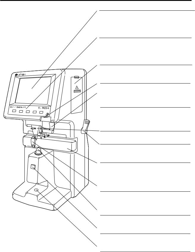
2.1 Front
LCD
Liquid crystal display displays information such as centering of lens, measurement conditions and results.
Control panel
Five buttons are located on this panel to control the unit. The function of each button is indicated above the button on the LCD display.
Printer
Prints out readings.
Contrast adjuster
Adjusts the contrast of the LCD.
Marking device
Marks the center and axis orientation of the lens.
Clamp
Stabilizes the lens when marking it.
Lever
Changes the position of the lens table.
Lens table
Used to standardize the orientation of spectacles for accurate cylinder axis measurement and verdical prism measurement.
Nose block
Used for PD measurement.
Nose piece
Lens is placed on the nose piece.
HOLD button
Used for holding and storing the data.
UV checker
Used to measure transmission ratio of Ultra Violet (UV) light.
2.1 Front |
2-1 |

2.2 Back
Name plate
Shows the serial number.
AC power terminal
The accompanying power cable is connected to this terminal.
Fuse holder
The fuse is mounted in this holder.
Power switch
Turns the power on or off.
External output terminal (RS-232C)
Prints the data when connected to a printer, or transmits the data when connected to a computer.
2-2 |
2.2 Back |
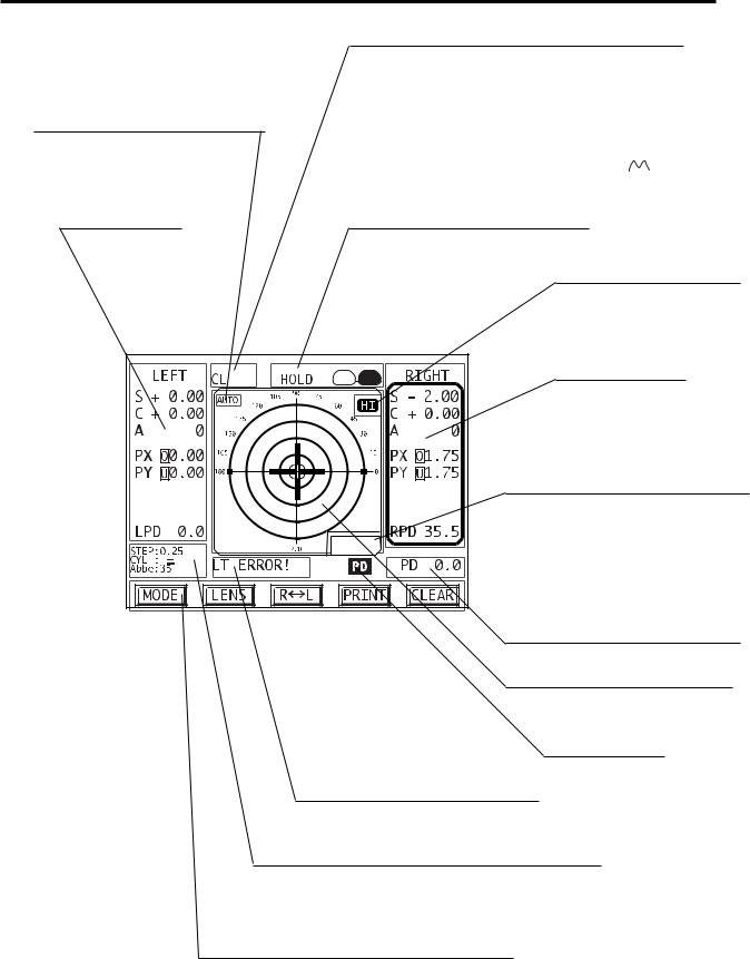
2.3 Screen layout
Indication of the automatic
measurement mode
AUTO : Automatic measurement mode
LEFT reading
Lens Modes
Single Vision mode: |
no message |
||
Progressive addition lens mode: |
PROG |
||
Bi-focal mode: |
Bi |
||
Tri-focal mode: |
Tri |
||
Contact lens mode: |
CL |
||
Contact Lens mode with a holder: |
CL |
|
|
|
|||
High Power Mode |
HP |
||
Holding data
HOLD : Indicates that the data
are being held.
HI
High index lens mode indicator
RIGHT reading
L Value
Displays distance from measuring point to lens table.
L=25
PD (Total pupillary distance)
Alignment screen
Centering with the cross bar
PD status
ON/OFF
Error display
The type of error is shown.
Data representation protocols
Indicates power increment (STEP), cylinder convention (CYL) and Abbe number.
Button indication
In each mode, each button on the panel below the LCD display is assigned a different function; the current function of each button is displayed by these five icons.
2.3 Screen layout |
2-3 |

2.4Buttons for operations
1)Display 1 ( 


 )
)
MODE: |
for switching between Control Panel Display 1and Control Panel |
||
|
|
|
Display 2. |
|
|
|
for entering Setup mode (by pressing and holding for approximately |
|
|
|
one second). |
LENS: |
for switching between single vision, multi-focal lens, contact lens and |
||
|
|
|
high power modes. |
R |
|
L: |
for switching from S-mode (for measuring single lenses) to RL-mode |
|
|||
|
|
|
(for measuring lenses mounted in spectacle frames) and for |
|
|
|
switching between the right and left lens. |
PRINT: |
for recalling and printing readings. |
||
CLEAR: for clearing stored readings (if any readings are in the memory). for changing from RL-mode to S-mode (if no readings are in the memory).
2) Display 2 ( 


 )
)
MODE: |
for switching between Control Panel Display 1 and Control Panel |
||||
|
|
|
Display 2. |
|
|
|
|
|
for entering Setup mode (by pressing and holding for approximately |
||
|
|
|
one second). |
|
|
+ |
|
- : |
for changing CYL reading (+, -) for the currently displayed lens(es) |
||
|
|||||
|
|
|
If you go back to Display 1, the CYL reading (+, -) returns to the |
||
|
|
|
default setting. It can be changed permanently in Setup Menu 1. |
||
PD: |
for changing PD mode (ON/OFF) |
||||
|
|
|
If the PD mode is ON, |
|
is shown on the lower right of the screen. |
|
|
|
|
||
UV: |
for using UV check function |
||||
PRISM: |
for changing prism mode (No display, Px/Py, PSM/BAS, DCx/DCy). |
||||
CAL: |
for calibration of UV check function (only appears in UV check |
||||
|
|
|
function). |
|
|
3) HOLD button
The HOLD button is used for storing a reading manually.
2-4 |
2.4 Buttons for operations |
3. METHOD OF OPERATION
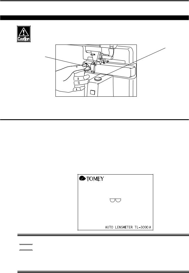
3.1 Preparation for operating
•Before turning on the power, check the following items:
- Make sure that the cover glass under the nose piece is clean.
Cover glass
Nose piece
-Make sure that a lens is not on the nose piece.
-Make sure that the nose piece is seated properly.
1)Connect the female end of the power cord into the power receptacle on the back of the Autolensmeter and the male end in to a 3-prong power outlet.
2)Press the power switch ON.
3)The initial screen will appear for approximately five seconds.


 • When the instrument is first turned on, the LCD (liquid crystal display) may appear dim. The brightness will increas as it warms up. This may require extra time if the ambient temperature is low.
3.1 Preparation for operating |
3-1 |

4) The measurement screen will appear.
L= 25
• Do not place a lens onto the nose piece until after the measurement screen appears.
•Turning the instrument on with the lens already on the nose piece initiates a beep and indicates "INITIAL ERROR" on the LCD. Remove the lens from the nose piece, then press any button to proceed.
3-2 |
|
|
|
|
|
|
|
|
|
|
|
|
|
|
|
|
|
|
|
|
|
|
|
|
|
|
|
|
|
|
|
|
|
|
|
|
|
|
|
|
|
|
|
|
|
|
|
|
|
|
|
|
|
|
|
|
|
|
|
|
|
|
|
|
|
|
|
|
|
|
|
|
|
|
|
|
|
|
|
|
|
|
|
|
|
|
|
|
|
|
|
|
|
|
|
3.1 Preparation for operating |
|
|
|
||||||||
3.2Measuring methods
3.2.1Measuring single vision lenses
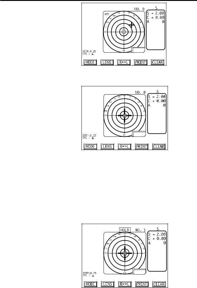
a)Measuring single lenses (lens blanks, S-mode)


 • In Auto mode, the reading will be automatically held when appropriate alignment is achieved. Change between AUTO mode and Manual mode by continuously pressing the HOLD button located below the nose piece for approximately one second.
•Do not push the lens against the nose piece with undue force or
move the lens abruptly, which may cause to damage the lens.
1)To measure a single lens, SINGLE mode must be set to ON in Setup (see section 3.4, Menu 4). If the instrument is in the RL-mode, press the CLEAR button to change to the S-mode. To change back to RL-
mode, press the R L button.
2)The nose block for PD measurement must be locked against the lens table by the clamp (toward the left side of the table).
3)Place the lens on the nose piece.
3.2.1 Measuring single vision lenses |
3-3 |
L= 25
4)Move the lens gently right and left, back and forth to center the cursor
(+)on the crosshair.
L= 25
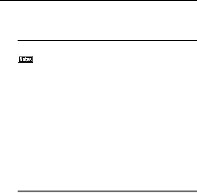
5)Measured data are displayed in real time. If the lens table is used, "L" (displayed at the bottom right of the alignment screen) indicates the distance between the measured point (center of nose piece) and the bottom edge of the lens.
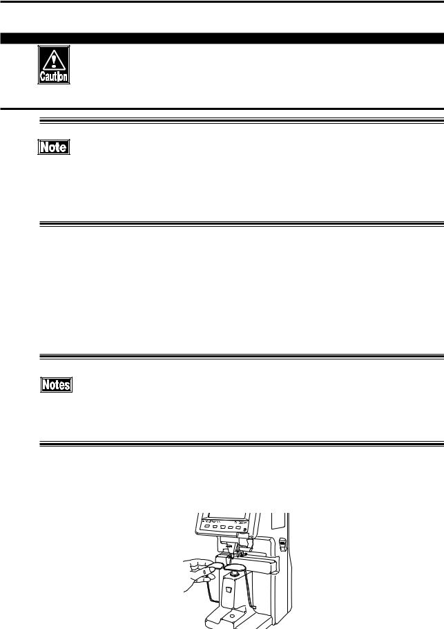
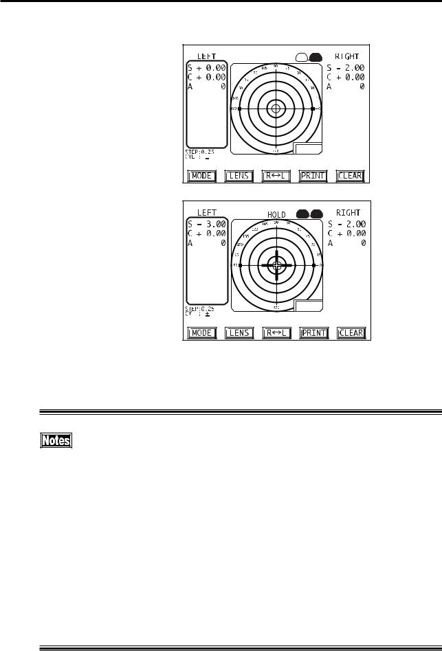
6)In Auto mode, the reading will be automatically acquired and held. In Manual mode, press the HOLD button when the lens is aligned to hold the measured data. The memory display will show HOLD and the stored data will be displayed. Up to 50 measurements can be stored (S-mode only).
L= 25
3-4 |
3.2.1 Measuring single vision lenses |
7)After removing the lens from the nose piece, the target ("+" mark) will disappear. It will reappear when another lens is placed on the nose piece.
8)Press the PRINT button to print all the data that have been stored. Until HOLD button is pressed next time, all data are retained.
•Pressing the HOLD button will allow the instrument to return to the measuring mode for taking new readings. ALL data for previously measured lenses are retained. However, if 50 measurements have been stored and the HOLD button is pressed, the message "OVER FLOW!" is displayed and indicates that there is no room to store additional readings. To continue measurement, it is necessary to either press the CLEAR button or print out the stored measurements by pressing the PRINT button before taking another reading.
•Pressing the CLEAR button erases ALL data that have been stored, i.e., data for all previously measured lenses are erased.
•If the SINGLE MODE menu setting is off, the S-mode cannot be activated. (See Section 3.4, Setup, Menu 4)
•Single lenses with power exceeding +/- 25D (up to +/- 80D) can be measured using the High Power Lens Mode (see Section 3.2.7 and Section 3.4, Setup Menu 2).
•If the PRINT menu setting is off, no printout can be made. (See Section 3.4, Setup, Menu 1).
3.2.1 Measuring single vision lenses |
3-5 |
b) Measuring framed lenses (RL-mode)
• Do not push the lens against the nose piece with undue force or move the lens abruptly, which may cause to damage to the lens.
• In Auto mode, the reading will be automatically held when appropriate alignment is achieved. Change between Auto mode and Manual mode by continuously pressing the HOLD button located below the nose piece for approximately one second.
1)If the instrument is in S-mode, Press the R<->L button to change to RL mode. The right lens is expected to be measured first and then the left lens. If you wish to measure the left lens before the right lens, press the R<->L-button again. A rectangle indicates the lens (R or L) to be measured. (Auto R/L may be turned ON or OFF; see Section 3.4, Setup Menu 3. The default setting is ON).
• If the nose block is not at the home position, the unit is in PD measurement mode and the R<->L-button is not functional (i.e., pressing it does not change between Right and Left).
2)Place the right lens on the nose piece with the bottom of the frame away from you and the temples downward (as shown below).
3-6 |
3.2.1 Measuring single vision lenses |
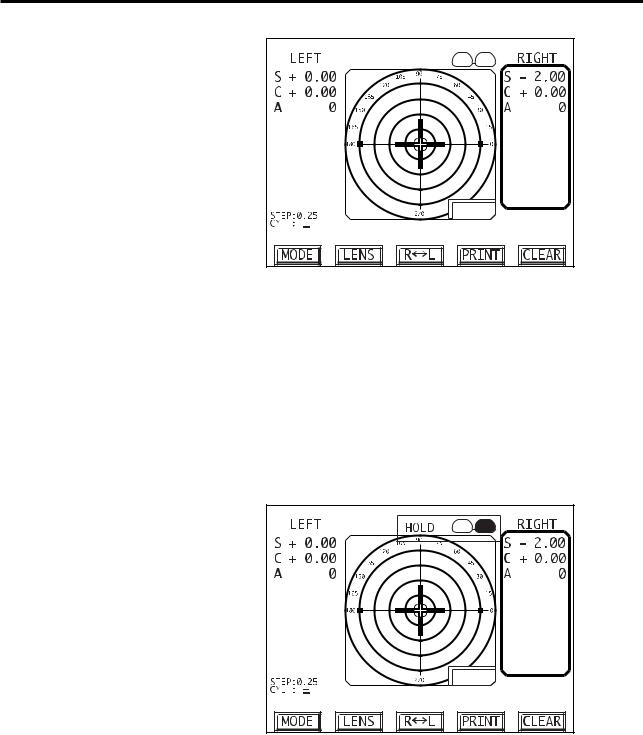
3) Move the lens back and forth to center the cursor (+) on the crosshair.
L= 25
4)Measured data are displayed in real time. If the lens table is used, "L" (displayed at the bottom right of the alignment screen) indicates the distance between the measured point (center of nose piece) and the bottom edge of the lens or frame.
5)In Auto mode, the reading will be automatically held when alignment is achieved. In Manual mode, press the HOLD button when the cursor is centered to store the data.
6)HOLD is shown in the memory display and the lens that has been measured becomes dark on the spectacle icon.
L= 25
7)When the lens is removed from the nose piece, the target (+) disappears. The "active" lens automatically switches to the other side, i.e., after the right lens has been measured, the instrument is ready to measure the left lens. If you wish to re-measure the right lens, press the R<->L button to reactivate "R" measurement.
3.2.1 Measuring single vision lenses |
3-7 |
8)When measurement of the right lens is completed, repeat the above steps to measure the left lens.
L= 25
L= 25
9)After both lenses have been measured, press the PRINT button to print the measurement.
10)The instrument is now ready to measure a right lens
• Pressing the HOLD button will allow the instrument to return to the measuring mode for taking new readings. ALL data for previously measured lenses are retained until you take the next reading. The new reading will replace the old reading that was stored in memory.
•Pressing the CLEAR button erases ALL data that have been stored, i.e., data for both the right and the left lens are erased.
•If a lens is placed on the nose piece without clearing the previous measurements, the stored data are cleared and the new reading will be displayed.
•If the PRINT menu setting is off, no printout can be made (See Section 3.4, Setup, Menu 1).
3-8 |
3.2.1 Measuring single vision lenses |

(This page is left intentionally blank.)
3-9

3.2.2 Measuring Multi-Focal Lenses
There are four multi-focal options (see Section 3.4, Setup Menu 2):
1) |
Progressive: |
for measuring progressive lenses |
2) |
Bi-focal: |
for measuring bifocal lenses |
3) |
Tri-focal: |
for measuring trifocal lenses |
4) |
Prog+Bi: |
for measuring progressive and bifocal lenses |
|
|
(default setting) |
(Note that the above options are for framed or single multi-focal lenses, not for multi-focal contact lenses.)
To change from Single Vision mode to Multi-Focal mode on the measurement screen, press the LENS button.
When the Single Vision option selected in Setup is Spectacle+CL, pressing the LENS button displays the measurement screens in the following order: Single Vision Mode for framed/single lenses, Multi-focal mode(s) for framed/single lenses and Contact lens mode. For example, if the PROG+Bi Multi-focal option is selected, pressing the LENS button changes the screen successively from Single Vision mode to Progressive mode to Bifocal mode to Contact lens mode.
When the Single Vision option selected in Setup is Spectacle, if the selected Multi-focal option is PROG+Bi, pressing the LENS button changes the screen successively from Single Vision framed/single lens mode to Progressive mode to Bifocal mode. If the selected Multi-focal option is Progressive or Bifocal or Trifocal, pressing the LENS button alternately changes between Single Vision mode and the selected Multi-focal mode.
3-10 |
3.2.2 Measuring Multi-Focal Lenses |
a) Measuring progressive addition lenses (PROG mode)
•Do not apply the lens to the nose piece with undue force or move it
abruptly, which may cause to damage lens.


 • When measuring in the Auto mode, the reading at the far area and ADD data at the near print area are held automatically. Press the HOLD button for approximately one second without a lens on the nose piece to alternately change between the Auto and the Manual mode.
•If you cannot make a proper measurement of progressive addition lenses, see "5.1 TROUBLESHOOTING".
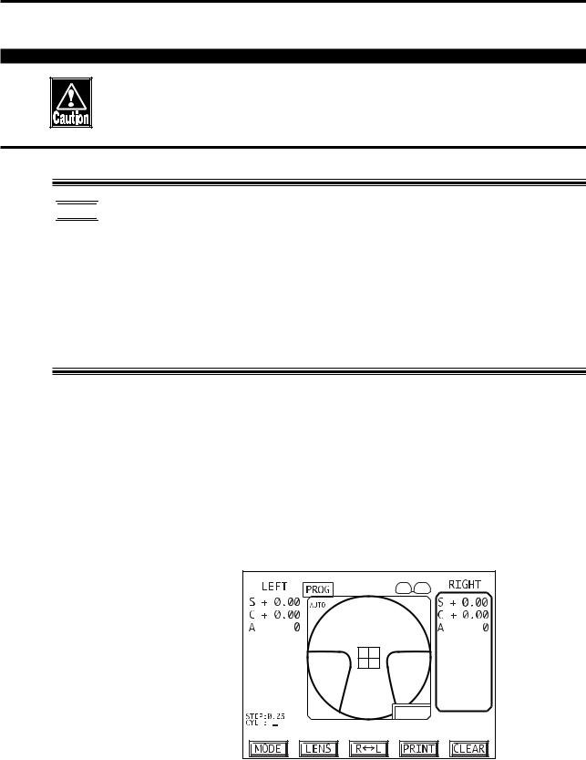
1)Select Progressive mode on the measurement screen by pressing the LENS button. (If Progressive mode is not available, go to Setup Menu 2 and change the Multi-Focal mode setting; see Section 3.4.)
2)Determine the extent of the progressive addition area.
a. Place the lens on the nose piece with the bottom of the frame away from you and the temples downward as illustrated on p.3-6 and, with the progressive addition area, which is located slightly below the center of the lens, above the nose piece.
L= 25
3.2.2 Measuring Multi-Focal Lenses |
3-11 |
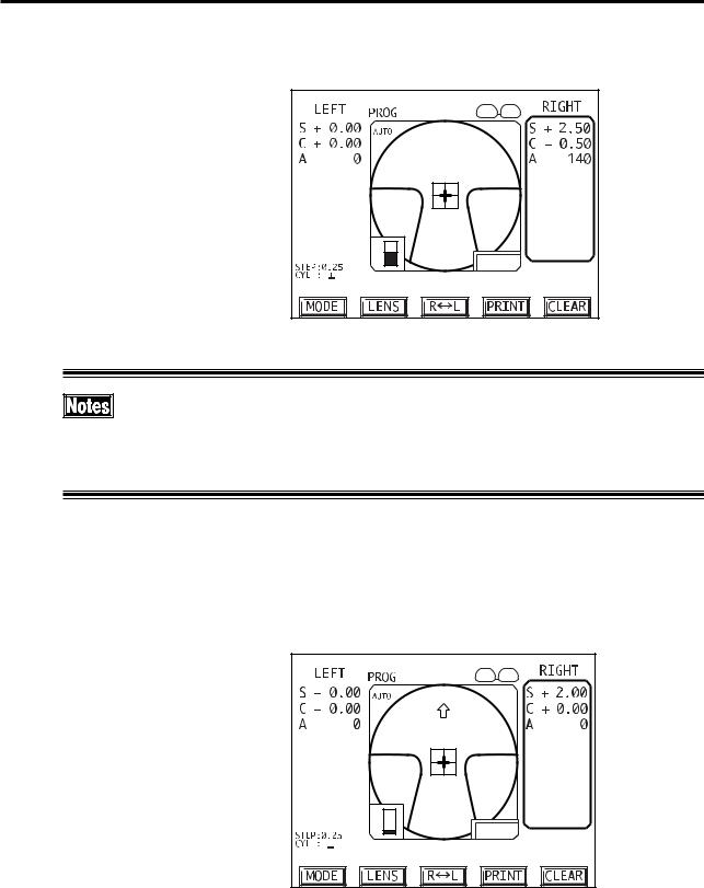
b.A bar graph indicating refractive power change at the point being measured in the progressive area appears at the left lower part of the target area.
L= 25 |
• If the add power is low, it may not be possible to center the target. In this case, place the center of the lens above the nose piece and press the HOLD button to proceed to far point measurement.
3)Measure the far point area.
a. Since the far point area is located in the top portion of the lens, move the lens away from you so that the top portion is over the nose piece. Move it back/forth and left/right to center the cursor (+) on the crosshair.
L= 25 |
b.When centering of the target is achieved, if in the Auto mode, a beep sounds and the far point power is automatically stored. If not in the Auto mode, it is necessary to press the HOLD button when the target is centered to store the data. (See 3.4 Setup, Menu 3.)
c.The display is next changed to that for measurement of the near point
3-12 |
3.2.2 Measuring Multi-Focal Lenses |
 Loading...