

Page 1
OPERATION MANUAL
Read this Operation Manual carefully before using the SP-100 for proper and safe operation.
If you come up any questions about this instrument or the Manual, ask your Tomey representative or local distributor.
yy
yy
y Do not use this instrument by any procedures other than those specified in this
Manual.
yy
yy
y Only well-trained or skilled personnel is allowed to operate this instrument.
yy
yy
y Keep the Operation Manual in a place where you can easily access while operating
the instrument.
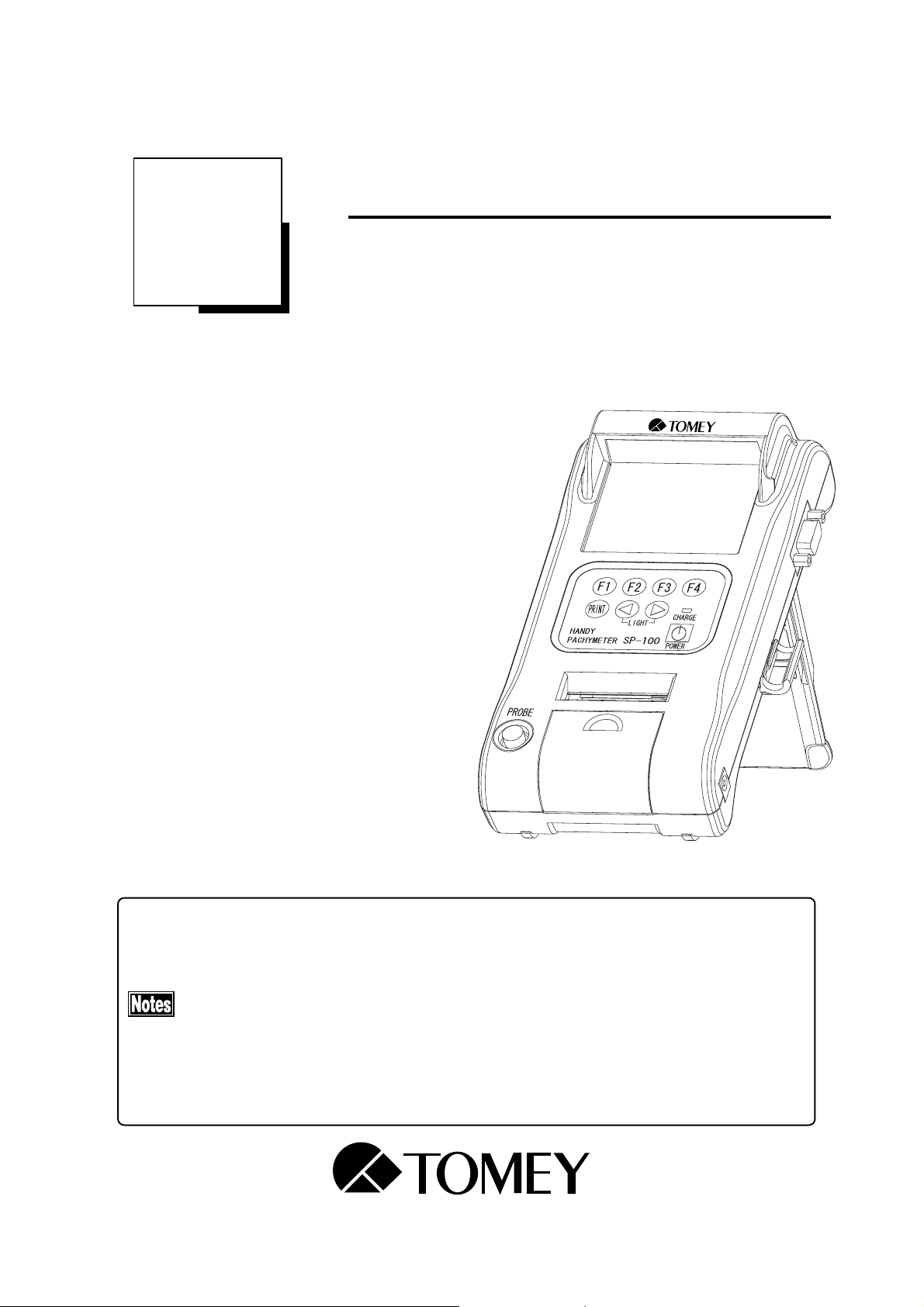
HANDY PACHYMETER
SP-100
Page 2

Page 3

WARNINGS
DO NOT USE THE INSTRUMENT WITH THE OUTER COVER AS LEFT
OPEN OR REMOVED, otherwise you may be exposed to direct high voltage.
Always use the sterilized or disinfected Pachymeter Probes for measurement.
NEVER USE the Probe if it may be subjected to any visible damage on its tip.
Such use may not only cause an incorrect measurement, but also damage the
cornea.
This instrument is designed exclusively for ophthalmic use.
DO NOT USE the instrument for any purpose other than ophthalmic use.
DO NOT connect the terminals of the instrument with any cable other than
those specified in the Manual, otherwise the instrument may be damaged.
SIGNIFICANT WARNINGS
i
Page 4

HOW TO USE THIS OPERATION MANUAL
THE COMPOSITION OF THE OPERATION MANUAL
The following items are provided for your efficient and effective use of
this instrument.
The Operation Manual is composed of the following parts.
1. PRIOR TO USE
Precaution and confirmation items related to the installation and us-
age of the instrument.
2. NAMES AND FUNCTIONS OF THE COMONENTS
Names and functions of the components of the instrument
3. OPERATING PROCEDURES
Vital information, required for installing and using the instrument
4. TECHNICAL INFORMATION
Useful technical information, which may be convenient for your use
5. MAINENANCE AND INSPECTION
Routine replacement, maintenance, and inspection, including replac-
ing spare parts
6. TROUBLESHOOTING
Countermeasures for troubles
7. SPARE PARTS AND OPTIONAL PARTS
Accessories and optional parts
8. SPECIFICATIONS
Specifications for the instrument
9. INDEX
ii
Refer to the index as a guide, if necessary.
HOW TO USE THIS OPERATION MANUAL
Page 5

SYMBOLS USED IN THE MANUAL
The symbols, such as "DANGER", "WARNING", "CAUTION" and "NOTE" used in this
Operation Manual, represent the following messages.
Precaution for an operation state that, if unheeded, will cause a haz-
ardous situation where there is an imminent danger of serious injury
or death.
Precaution for an operation state that, if unheeded, may cause a haz-
ardous situation where there is the possibility of serious injuries or
death.
An operational precaution that, if unheeded, may cause or lead to
minor or moderate injuries or property damages.
Special precaution that is related either directly or indirectly to per-
sonal safety or to property protection.
SYMBOLS USED IN THE MANUAL
iii
Page 6

Contents
1. PRIOR TO USE ............................................................................................................. 1-1
1.1 Precautions..................................................................................................................................... 1-1
1.2 Unpacking ...................................................................................................................................... 1-3
1.3 Symbols, used in this manual ........................................................................................................ 1-4
1.4 Outline of Measurement Principle .................................................................................................. 1-5
2. NAMES AND FUNCTIONS OF THE COMPONENTS ................................................... 2-1
2.1 Front and Right side of Main Unit ................................................................................................... 2-1
2.2 Rear and left side of Main Unit ....................................................................................................... 2-1
2.3 Operation Keys .............................................................................................................................. 2-2
3. OPERATING PROCEDURES ........................................................................................ 3-1
3.1 Safety precautions .......................................................................................................................... 3-1
3.2 Preparation before operation ......................................................................................................... 3-2
3.2.1 Connection of accessories ........................................................................................... 3-2
3.2.2 Disinfection of the probe ............................................................................................... 3-2
3.2.3 Optional components ................................................................................................... 3-3
3.3 Adjustment and Setting .................................................................................................................. 3-4
3.3.1 Main power on and screen adjustment ........................................................................ 3-4
3.3.2 Startup Display .............................................................................................................. 3-5
3.3.3 Screen Contents ........................................................................................................... 3-7
3.3.4 Measuring conditions ................................................................................................... 3-9
3.4 Preparation for measurement ........................................................................................................ 3-12
3.4.1 Calibration of the Probe ...............................................................................................3-12
3.4.2 Operation Check ..........................................................................................................3-13
3.4.3 Measurement Preparation for Patient .......................................................................... 3-13
3.5 Measurement.................................................................................................................................3-14
3.5.1 Single measurement .................................................................................................... 3-15
3.5.2 Delete Each Data Reading ..........................................................................................3-16
3.5.3 Delete Data (Eye by eye or patient by patient) ...........................................................3-17
3.6 Printout ...........................................................................................................................................3-19
3.6.1 How to Printout the data ...............................................................................................3-19
3.6.2 Description of Printout ..................................................................................................3-20
3.6.3 IOP Calculation Printout ...............................................................................................3-21
3.7 Menu .............................................................................................................................................. 3-22
3.7.1 Description of the Screen display ...............................................................................3-22
3.7.2 Operation for the MENU Screen ..................................................................................3-23
3.7.3 Operating procedures of the Menu Screen ................................................................3-24
iv
CONTENTS
Page 7

3.7.4 IOP Calculation .............................................................................................................3-29
3.8 Sending and receiving data .......................................................................................................... 3-32
3.8.1 How to connect the serial communication cable ......................................................... 3-32
3.8.2 Setting of communication conditions ...........................................................................3-33
3.8.3 Data Export .................................................................................................................. 3-35
3.8.4 Data Receiving ............................................................................................................. 3-37
3.9 Data Management with TOMEY Link (Electronic Modical Record Support System) ...................3-39
3.9.1 Patient Data Receiving ................................................................................................. 3-39
3.9.2 Data Sending ...............................................................................................................3-41
3.10 Battery ...........................................................................................................................................3-43
3.10.1 Battery charge balance ................................................................................................3-43
3.10.2 Low Battery Warning .................................................................................................... 3-44
3.10.3 Charge indicator ...........................................................................................................3-45
3.10.4 How to Install / Uninstall Battery ...................................................................................3-45
3.10.5 Lifetime of rechargeable battery .................................................................................. 3-46
3.10.6 Expected operating time of hours ............................................................................... 3-46
4. REFERENCE TECHNICAL INFORMATION .................................................................. 4-1
4.1 How to calculate corneal thickness ................................................................................................ 4-1
4.2 Acoustic Output .............................................................................................................................. 4-1
4.2.1 MI (Mechanical Index) ....................................................................................................... 4-1
4.2.2 TIS (Soft Tissue Thermal Index) ........................................................................................ 4-1
5. MAINTENANCE AND INSPECTION .............................................................................. 5-1
5.1 Warranty .......................................................................................................................................... 5-1
5.2 Routine maintenance ...................................................................................................................... 5-2
5.2.1 Measurement Probe ..................................................................................................... 5-2
5.2.2 Maintenance of the Main Unit ........................................................................................ 5-4
5.3 Replacing of the printer paper ....................................................................................................... 5-5
5.4 Storage........................................................................................................................................... 5-6
5.5 Precautions for disposal of packing materials ............................................................................... 5-6
6. TROUBLESHOOTING ................................................................................................... 6-1
7. SPARE PARTS AND OPTIONAL PARTS ....................................................................... 7-1
7.1 Spare parts ..................................................................................................................................... 7-1
7.2 Optional parts ................................................................................................................................. 7-1
8. SPECIFICATIONS.......................................................................................................... 8-1
8.1 Specifications ................................................................................................................................. 8-1
8.1.1 Measuring function ........................................................................................................ 8-1
8.1.2 Measuring Probe .......................................................................................................... 8-1
CONTENTS
v
Page 8

8.1.3 Main unit ........................................................................................................................ 8-1
8.1.4 AC Adapter ................................................................................................................... 8-1
8.1.5 Enclosed battery ........................................................................................................... 8-1
8.2 Ultrasound energy and other information ....................................................................................... 8-2
8.2.1 Influences of ultrasound energy on the human body ................................................... 8-2
8.2.2 Ultrasound energy ........................................................................................................ 8-2
8.3 Noise Generation ........................................................................................................................... 8-4
8.4 Operating Environment................................................................................................................... 8-4
8.5 Conformed Standard ...................................................................................................................... 8-4
9. INDEX ............................................................................................................................ A-1
vi
CONTENTS
Page 9

1. PRIOR TO USE
Make sure that the instrument is free from any equipment
Care must be taken not to place any object on the instru-
Be sure to read this Manual before using the instrument
Do not use the instrument in any procedures other than
1.1 Precautions
that may cause an intensive magnetic field, which other-
wise causes the instrument with noises or may make it
unable to allow correct diagnosis or measurement.
ment.
for your safe and correct operation.
specified in this Manual.
Though measuring accuracy is +/- 5
measurement may be out of the measuring accuracy, depending on
condition of cornea. Please review and retake the measurement or try
other inspections, when the result seems to be suspicious with past
corneal medical history of the patient.
Only skilled operators are allowed to use this instrument.
When installing the instrument, observe the following items.
- Install the instrument in a place where it is free from water and/or
chemicals.
- Install the instrument in a place where it is free from such adverse
influences as direct sunbeams, high temperature and moisture, dust, and
salts or sulfur-contained air.
- Install the instrument in a stable place where it is free from inclination,
vibration, and/or shocks.
- Do not install the instrument in or near the store area of chemical
substances or a place where any gas is generated.
- Use specified frequency, voltage and allowable current (or allowable
µµ
µ
m, accuracy with actual
µµ
power consumption).
- Make sure that the conditions of power source (discharge, polarity, etc)
are proper.
1.1 Using precautions
1-1
Page 10

Observe the following items before using the instrument.
- Check on the settings of switch connections, polarity, and volumes and
make sure that the instrument operates accurately.
- Make sure that all the cord connections are made properly.
- Recheck the components or parts that directly touch the Patient.
Observe the following items when you use the instrument.
- Avoid using an excessive period of measurement for each Patient.
- Closely and continuously watch to check to see if the instrument works in
normal condition and the Patient is secured in safe condition.
- If any abnormal condition is found with the instrument or the Patient,
take appropriate actions or remedy, first to secure Patient's safety and
next to stop the operation of the instrument.
- Sufficient care should be given not to cause the Patient to touch the
instrument while the instrument is in operation.
Observe the following items after using the instrument.
- Before turning the power off, return the instrument to its original
condition in specified procedure.
- Do not apply undue force to the power cable when disconnecting, such as
by pulling the cord itself.
- As for storing the instrument and related components, see "5.4 Storage"
in this Manual.
- Store the Pachymeter Probe, accessories, and cords in order after
cleaning them properly.
- Be sure to properly clean the instrument to be ready for your next use.
It is advised that in case the instrument is disorderd, stop using the
instrument and contact your TOMEY representative for corrective
inspection and/or repair.
Do not uncover except battery cover or remodel the main instrument in
any ways.
Do not remodel or redesign the instrument, or the Warranty will be
invalid.
Periodical inspection should be given to the instrument and related
components.
1-2
When using the instrument after recess for a while, make sure that it
operates properly and safely.
Please USE AC power adapter provided from TOMEY as SP-100
standard accessory. When using other AC power adapters, the warranty
will be invalid and the unit may not work properly.
1.1 Using precautions
Page 11

1.2 Unpacking
Make sure, when unpacking the shipment, the instrument, including probe and
supplies all arrived at your place in their proper conditions. Check these com-
modities on any damages and malfunctions.
Be sure to keep all the shipping and packing materials,
which may be used when the instrument is moved to the
other place.
z Main unit, HANDY PACHYMETER SP-100
(Lithium-Ion Battery Included) ....................................... 1
z Pachymeter Probe
(with the protective cap and the case) ......................... 1
z Pachymeter test piece .................................................... 1
z AC adapter ................................................................... 1
z Printer paper roll (1 roll in the instrument) ....................... 3
z Serial communication terminal protective cap .................. 1
z Operation Manual (this manual) ...................................... 1
z Carrying Bag ................................................................. 1
z Inner Case ..................................................................... 1
z Quick Guide .................................................................. 1
1.2 Unpacking
1-3
Page 12
1.3 Symbols, used in this manual
The terms and symbols, used for the instrument, shall imply the following means.
PROBE Pachymeter probe terminal
Connects the Probe to this terminal.
Power Switch
Turns main power ON and OFF.
Contrast adjusting volume
Adjusts the contrast of the monitor
Serial communication terminal
Various data is sent and received through the external
by using the serial communication cable.
Maintenance switch
This switch should be used for maintenance purpose only
Do not touch this switch for changing.
AC adapter terminal
Connects the AC adapter, included in the box.
1-4
1.3 Symbols used in this manual
Page 13

1.4 Outline of Measurement Principle
After taking measurement, the oscillator is not emitting
ultrasound waves.
The SP-100 is designed for pachymeter or corneal thickness measurement by
using ultrasound transducer, built in Pachymeter probe.
z SP-100 emits the ultrasound from the Pachymeter probe and the
probe also receives the ultrasound reflected by surface between
corneal posterior face and anterior chamber.
z SP-100 measures the period of time from emitting ultrasound to
receiving the same ultrasound, reflected by corneal posterior part.
Applying a calculation formula shown below, corneal thickness
can be calculated.
V · t
L = ———
z This instrument is powered by rechargeable battery or AC power
adapter. Even when the battery power is running short, SP-100
can perform measurements, while charging the battery, by plug-
ging to AC power adapter.
z This instrument is designed to take corneal thickness measure-
ment automatically, when the probe is applied to cornea properly.
2
Where, L: Corneal Thickness
V: Converted sound velocity
(Ultrasound Velocity through cornea)
T: Measured time (Ultrasound transmission
time between emitting and receiving)
z This instrument is capable of sending and receiving patient infor-
mation and measurement data between the external equipment
through the serial communication port. (Additional cable must be
used, when using this function)
1.4 Outline of Measurement Principle
1-5
Page 14

This page is left intentionary blank.
1-6
Page 15
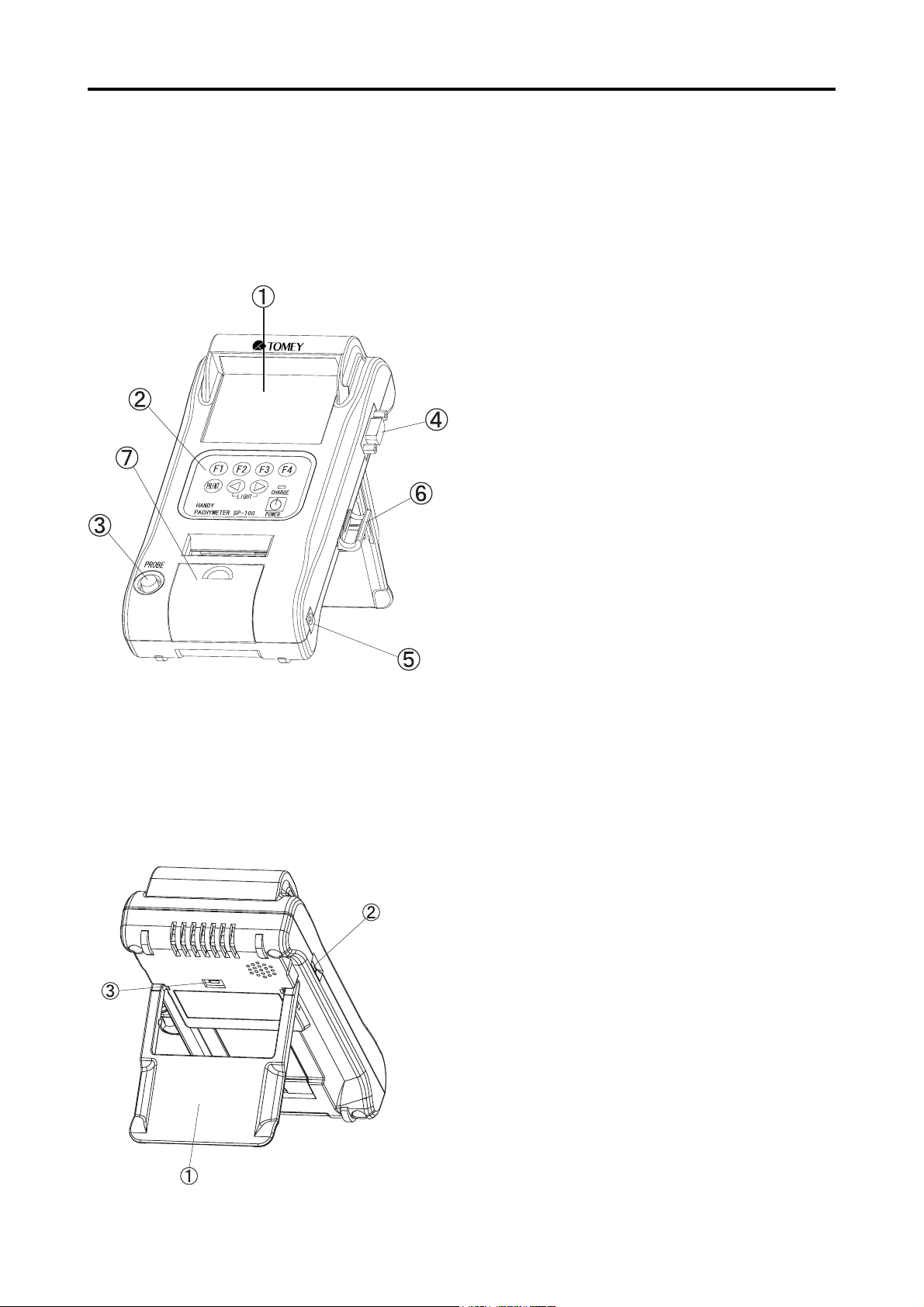
2. NAMES AND FUNCTIONS OF THE COMPONENTS
2.1 Front and Right side of Main Unit
AA
A SCREEN
AA
Measurement data and other information can be
displayed.
B B
B OPERATING PANEL
B B
The keys are located on the panel with various
functions.
CC
C PACHYMETER PROBE TERMINAL
CC
Pachymeter Probe should be connected to this
terminal.
DD
D SERIAL COMMUNICATION TERMINAL
DD
Serial Communication Cable can be connected
for data communication.
EE
E AC ADAPTER TERMINAL
EE
AC Adapter can be connected for supplying
power for operation and charging battery.
FF
F PROBE HOLDER
FF
Pachymeter Probe can be hold and kept as stable
position. Use the holder, while the probe is not
in use.
GG
G BUILT-IN THERMAL PRINTER
GG
Patient and Measurement information can be
printed by selected Standard or Simple mode.
2.2 Rear and left side of Main Unit
AA
A INSTRUMENT STAND
AA
The main unit stands on desk tilted for easy operation and monitoring.
BB
B CONTRAST VOLUME DIAL
BB
LCD contrast can be adjusted.
CC
C MAINTENANCE SWITCH
CC
This Switch is for maintenance use only. DO
NOT change any setting this switch, or the unit
is damaged.
2.1 Front and Right side of Main Unit 2.2 Rear and left side of Main Unit
2-1
Page 16
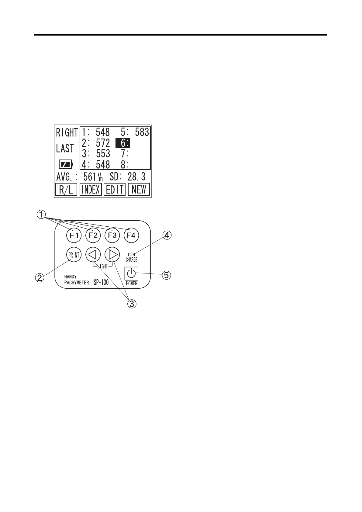
2.3 Operation Keys
General key assignments are explained in this part. However, other functions
are assigned on the same key, depending on the screen. Read each part of the
manual carefully in order to understand the key operation completely.
(Example)
AA
A FUNCTION KEYS
AA
Each key works as assigned function shown on
the bottom of the screen. Four boxes from left
to right on screen indicate each function of F1,
F2, F3 and F4 keys.
BB
B PRINT KEY
BB
Patient and Measurement Data can be printed
by built-in thermal paper. Please refer to [3.6
Printout] for details.
CC
WW
C
CC
DD
D CHARGE INDICATOR
DD
EE
E POWER KEY
EE
XX
W,
X KEYS
WW
XX
Data selection, Patient ID & Name can be typed
in by using the keys. Press both keys simultaneously to turn LED ON and OFF. (When the
unit is only powered by battry and no operation
for one minute, it automatically turns LED off)
The light keeps turning ON, while charging the
internal battery. When it turns OFF, charging
battery is completed.
The main power turns ON and OFF. When the
unit is only powered by battery and no operation for three minutes, it automatically turns OFF
to save battery power. (Auto Power OFF)
2-2
(F-keys Example) Each key, on this page, is assigned its func-
tion as follows:
x F1 ........... R/L
x F2 ........... INDEX
x F3 ........... EDIT
x F4. .......... NEW
2.3 Operation Keys
Page 17

3. OPERATING PROCEDURES
3.1 Safety precautions
The Probe must always be disinfected before its use.
Never use the Probe, if there is any visible damage on its tip, which may
otherwise cause an incorrect measurement or damage the cornea.
This instrument is Ophthalmic Medical Device, designed for only skilled
operators.
- Do not use this instrument other than Ophthalmic applies.
Do not use any terminal other than specified in this Operation Manual,
which may otherwise cause to damage the instrument.
Do not leave the instrument plugged with the AC Adapter when the
battery is fully charged, otherwise, this may enshorten the lifetime of
built-in rechargeable battery.
When the probe is not in use, please place the probe cap and place the
probe to the holder to protect from getting damaged.
3.1 Safety precautions
3-1
Page 18
3.2 Preparation before operation
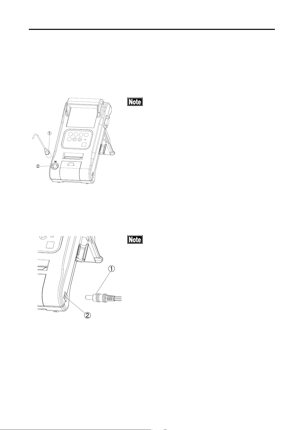
3.2.1 Connection of accessories
a) Connection of Pachymeter Probe
Connector of the Probe should be inserted in speci-
fied direction. Insert the connector as deep as it
sounds "click".
Insert the connector A into the connecting terminal B
marked "PROBE" on the front side of Main Unit.
b) Connection of AC Adapter
3.2.2 Disinfection of the probe
Insert the connector to the terminal completely
Insert AC adapter connector A into the connecting terminal B provided on the right side of the Unit.
Disinfect the probe with proper procedure, before its use. Please
3-2
refer to [5.2.2 Disinfecting Pachymeter Probe] for details.
3.2 Preparation before operation
Page 19
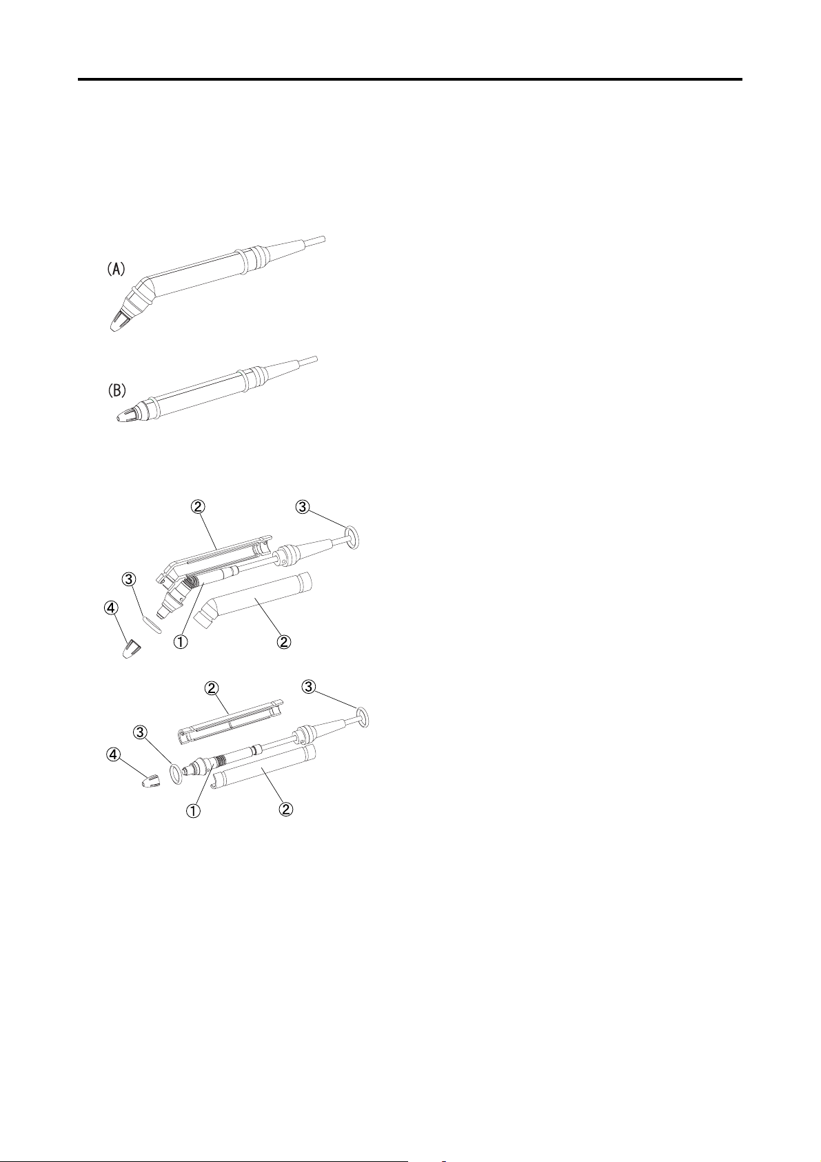
3.2.3 Optional components
Assembling of the Disposal Tip Pachymeter Probe and alternative Probe shapes
The Disposal Type Pachymeter Probe (supplied as
an optional component) consists of the inner probe,
case, fixed ring, and disposal tip.
The Probe can be changed in two alternative shapes:
(A) with 45 shape and (B) in straight shape, de-
pending on the application convenience.
<How to assemble>
1) Cover the inner probe A with a pair of cases
B to make the inner probe clipped in between
and fix it with the rubber rings C.
2) Apply a small amount of methylcellulose (such
as Dry Eye Gel) on the tip of the inner probe
A.
3) Then securely insert the disposal tip D not to
cause air bubbles inside of the tip.
<How to assemble the Probe in alternative shape>
1) Disassemble the disposal tip D, fixed ring C,
and the case B in order.
2) Assemble the case B to be changed and next
fix it with the rings C.
3) Next apply a small amount of methylcellulose
to the tip of the inner probe.
4) Then securely insert the disposal tip D not to
cause air bubbles inside of the tip.
3.2 Preparation before operation
3-3
Page 20
3.3 Adjustment and Setting
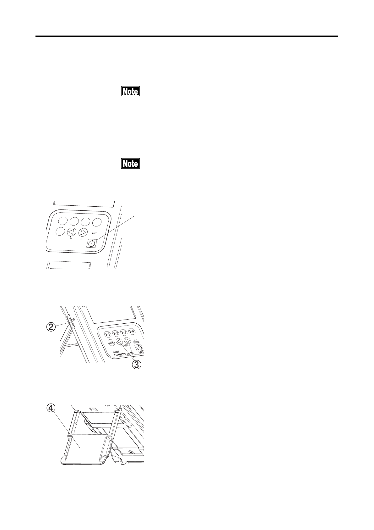
3.3.1 Main power on and screen adjustment
Confirm the following items before turning the power on.
xx
x
Make sure the battery is sufficiently charged. If not, con-
xx
nect the AC adapter for power supply. (With battery opera-
tion and 3 minutes of non operating time, the unit goes
into Auto Power off mode and measured data will be lost)
xx
x Make sure the Probe has been connected.
xx
xx
x Make sure the tip of the Probe is dry.
xx
Tilt the LCD screen on the proper position in order to get bet-
ter view from the front
Ԙ
(
(
(
(
24+06
*#0&;
2#%*;/'6'452
.+)*6
%*#4)'
219'4
1) Press the power key A to start operation. The
instrument will automatically calibrate the con-
nected Probe. If "PROBE ERROR!" is displayed
on the screen, check if the tip of the Probe is dry.
(Refer to [3.3.2 Startup Display] for details)
(Fig. 1)
(Fig. 2)
2) Adjust the LCD contrast, according to the
brightness of the clinical room by using contrast adjusting dial B on the left side of the
unit.
When the room is dark, press the "W " and "X"
keys C simultaneously to turn the lighting LED
on.
3) Adjust Instrument Stand D on back of the unit to
tilt it to get better screen view.
3-4
(Fig. 3)
3.3 Adjustment and Setting
Page 21
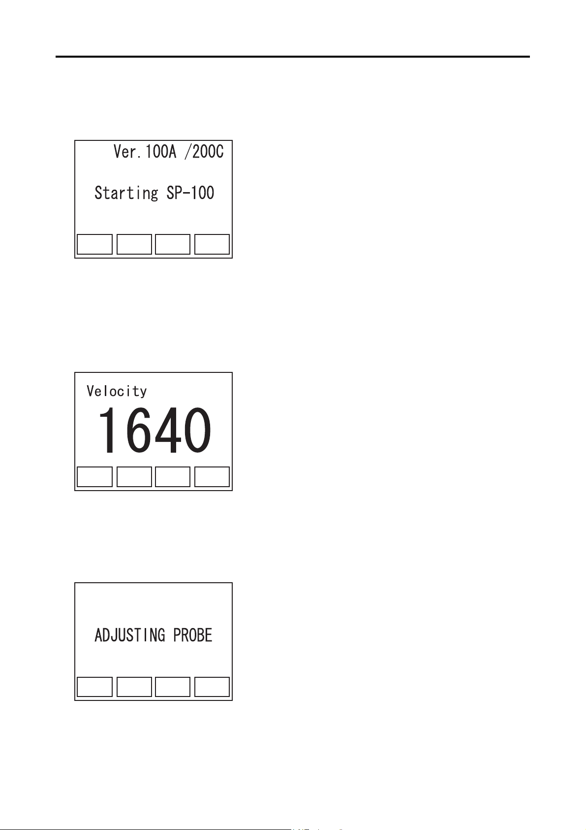
3.3.2 Startup Display
(Fig. 1)
1) The startup screen is displayed immediately af-
ter the power is on. The software version is seen
on the screen.
(Fig. 1)
2) The ultrasound velocity, set for measurement, is
(Fig. 2)
displayed.
(Fig. 2)
3) The unit calibrates the probe automatically.
(Fig. 3)
(Fig. 3)
3.3 Adjustment and Setting
3-5
Page 22
(Fig. 4)
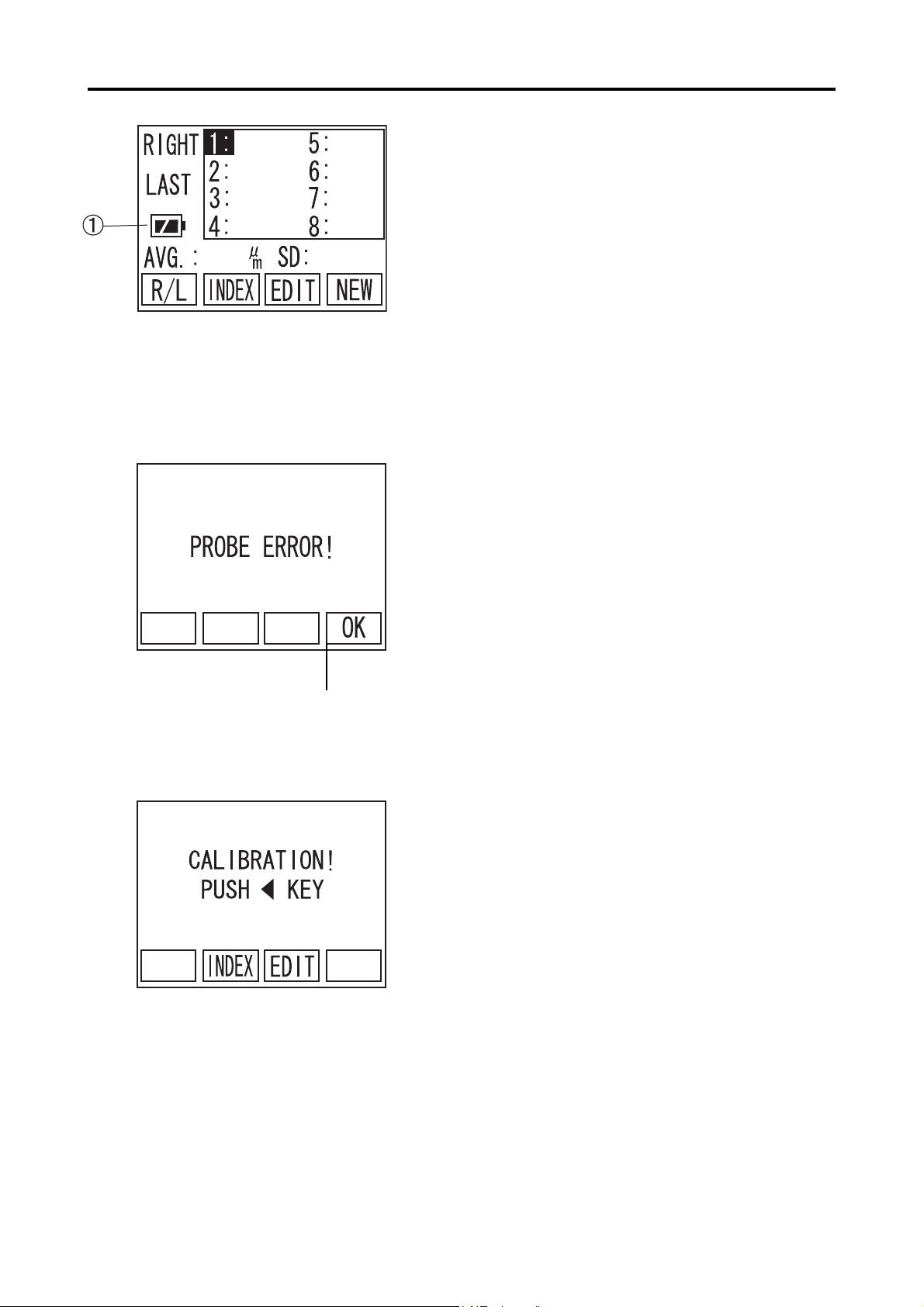
4) When the calibration has been completed prop-
erly, measurement Pachy screen (initial screen)
is displayed.
(Fig. 4)
5) When the Probe is not calibrated properly,
"PROBE ERROR!" will be displayed. Press F4
key A "OK" (Fig. 5) to show CALIBRATION
screen (Fig. 6).
(Fig. 5)
(Fig. 6)
A
6) Check the connection of the Probe and the
Probe tip, then press the "W " to recalibrate the
Probe.
When error appears in the screen, go to "6.
TROUBLE-SHOOTING" for the solution.
When "ERROR" repeatedly appears, contact
3-6
TOMEY representative.
3.3 Adjustment and Setting
Page 23
3.3.3 Screen Contents
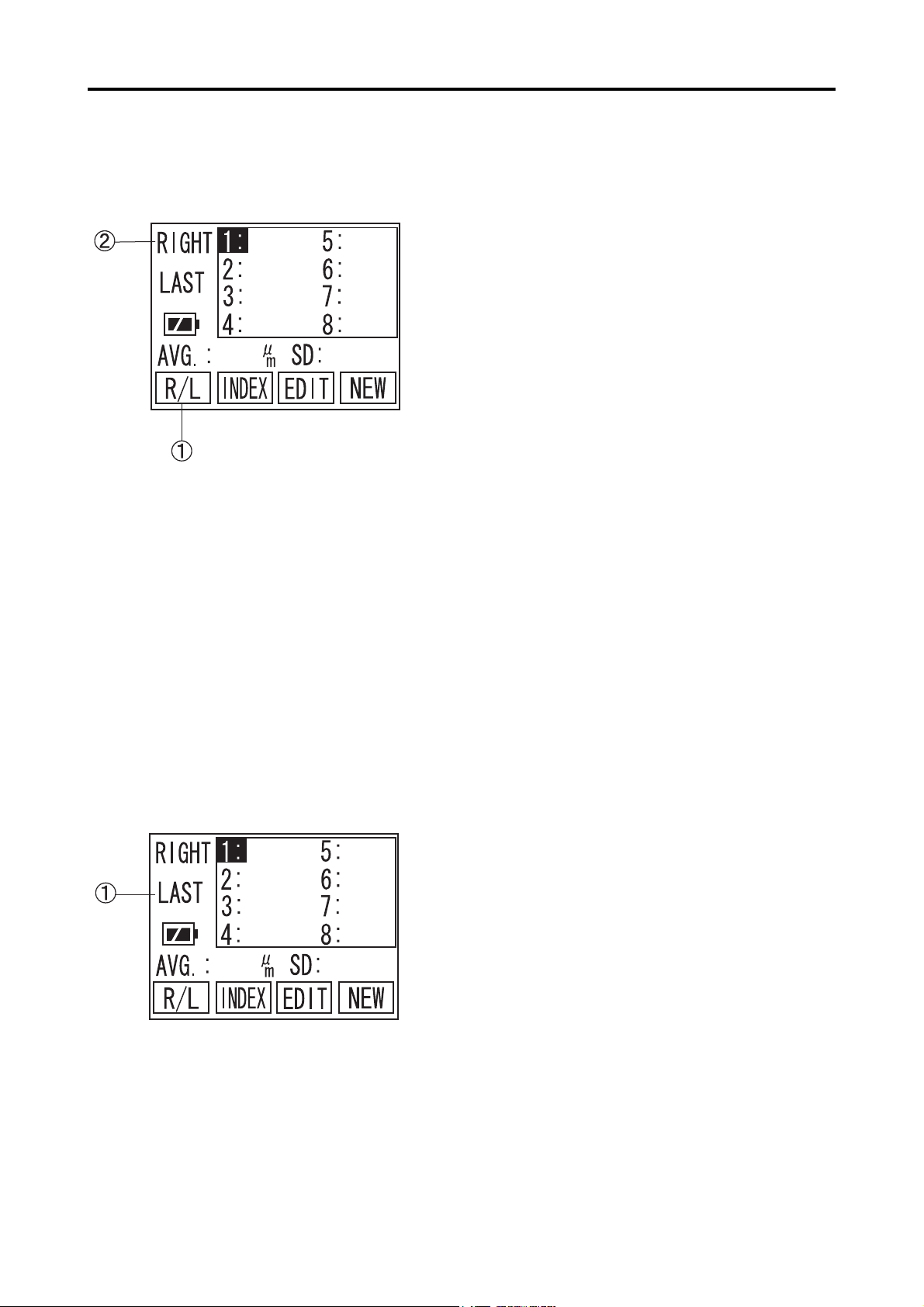
a) Pachy screen
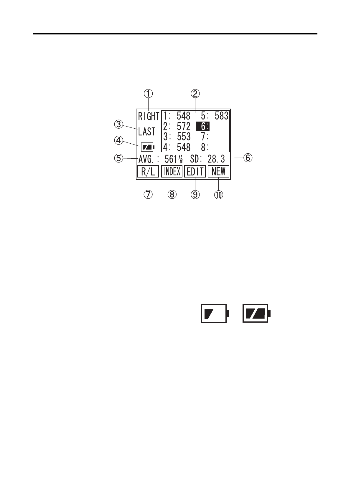
A The eye to be measured
Either left or right eye, to be measured, is selected on this part of the screen.
B Measurement data
The data, taken by the unit will be listed.
C Average
Average value of the listed data will be displayed.
D Battery Life Indicator
Remaining power in the built-in battery
appears. (Two Steps)
E Type of listed data
Average, Minimum or Latest options can be selected as a type of listed data
F R/L (F1 key)
Left or right eye for measurement is switched over.
G INDEX (F2 key)
Switch screen to INDEX, to input Patient ID and name.
H EDIT (F3 key)
Switch screen to EDIT, to edit measured data
I NEW (F4 key)
To measure new patient, use this key to clear Patient data and measured readings.
3.3 Adjustment and Setting
3-7
Page 24
b) Measurement screen
c) Edit screen
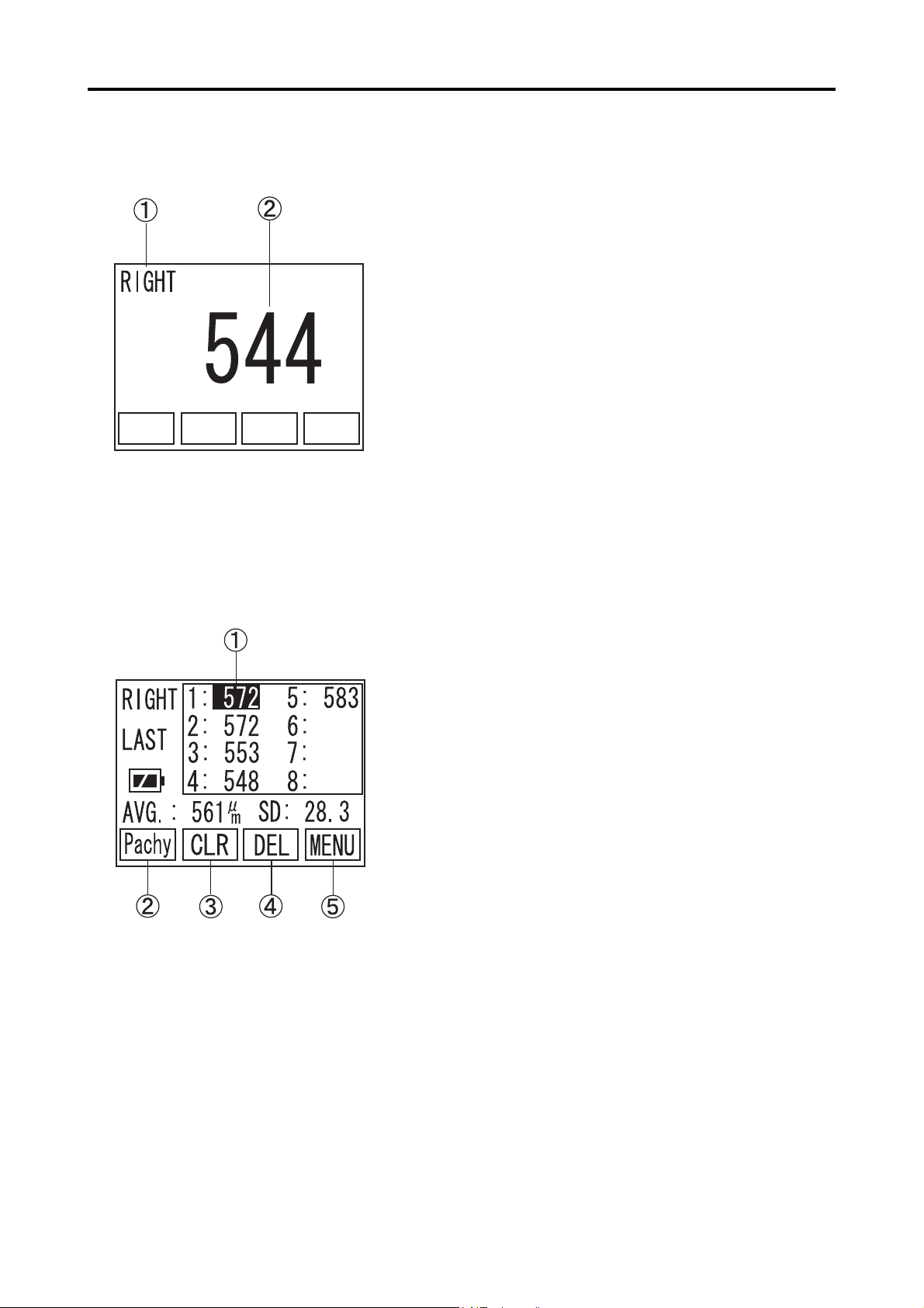
A The eye to be measured
Either left or right eye, to be measured, is selected on this part of the screen.
B Measurement data
The data, taken by the unit will be listed.
While taking measurement, the screen automatically
changes and shows large size measuring data.
A Cursor
Selected data is highlighted on the list. Other
data is selected by using "W" or "X" keys.
B Pachy (F1 key)
Press this key to change screen to Pachy mode.
C CLR (F2 key)
Press this key and keep holding it to clear all
measurement data.
D DEL (F3 key)
Press this key and keep holding it to clear only
highlighted measurement data
E MENU (F4 key)
Press this key to change into MENU screen.
3-8
3.3 Adjustment and Setting
Page 25
3.3.4 Measuring conditions
a) Input Patient ID and name
The Patient ID and name are input in the "INDEX" screen. 14 letters can be
The following measuring conditions have been set, when turning
the power on.
Eye to be measured: Right eye (OD)
Corneal ultrasound velocity: Last value, when it is turned off.
Please refer to "3.9 Data Management with TOMEYLink
(Electronic Medical Record Support System)" to send Data to
TOMEYLink.
In case of using Data Communication, Patient ID must be
typed in. Otherwise the data cannot be sent.
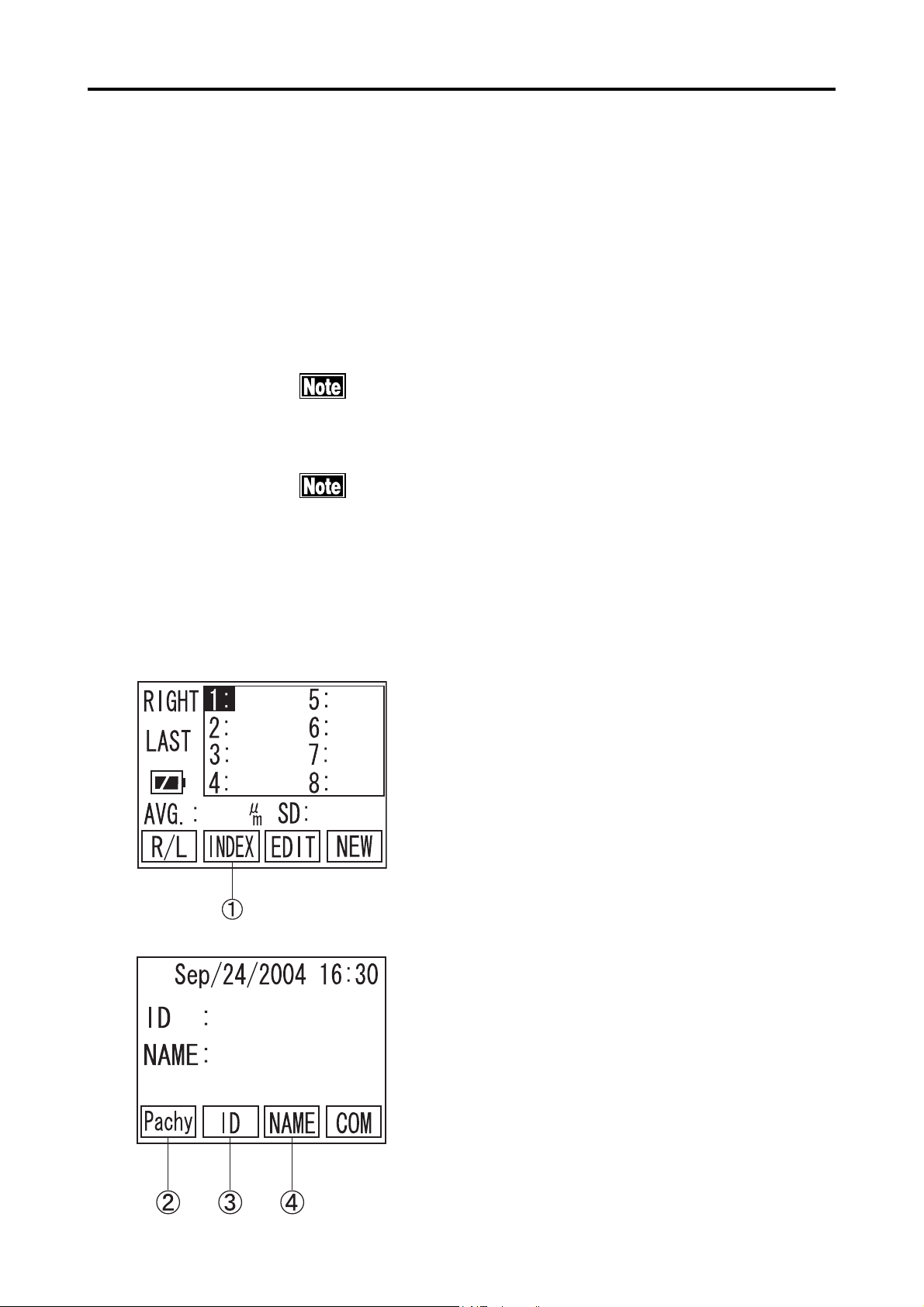
(Fig. 1)
typed in either the Patient ID or Patient name.
1) Press F2 key A to change into INDEX Screen.
(Fig. 2)
2) Press F2 key C to change into ID input screen
to type in Patient ID. (Fig. 3)
Press F3 key D to change into Patient NAME
input screen to type in Patient Name. (Fig. 4)
(Fig. 2)
F1 key B to go back to Pachy Screen (Fig. 1).
3.3 Adjustment and Setting
3-9
Page 26
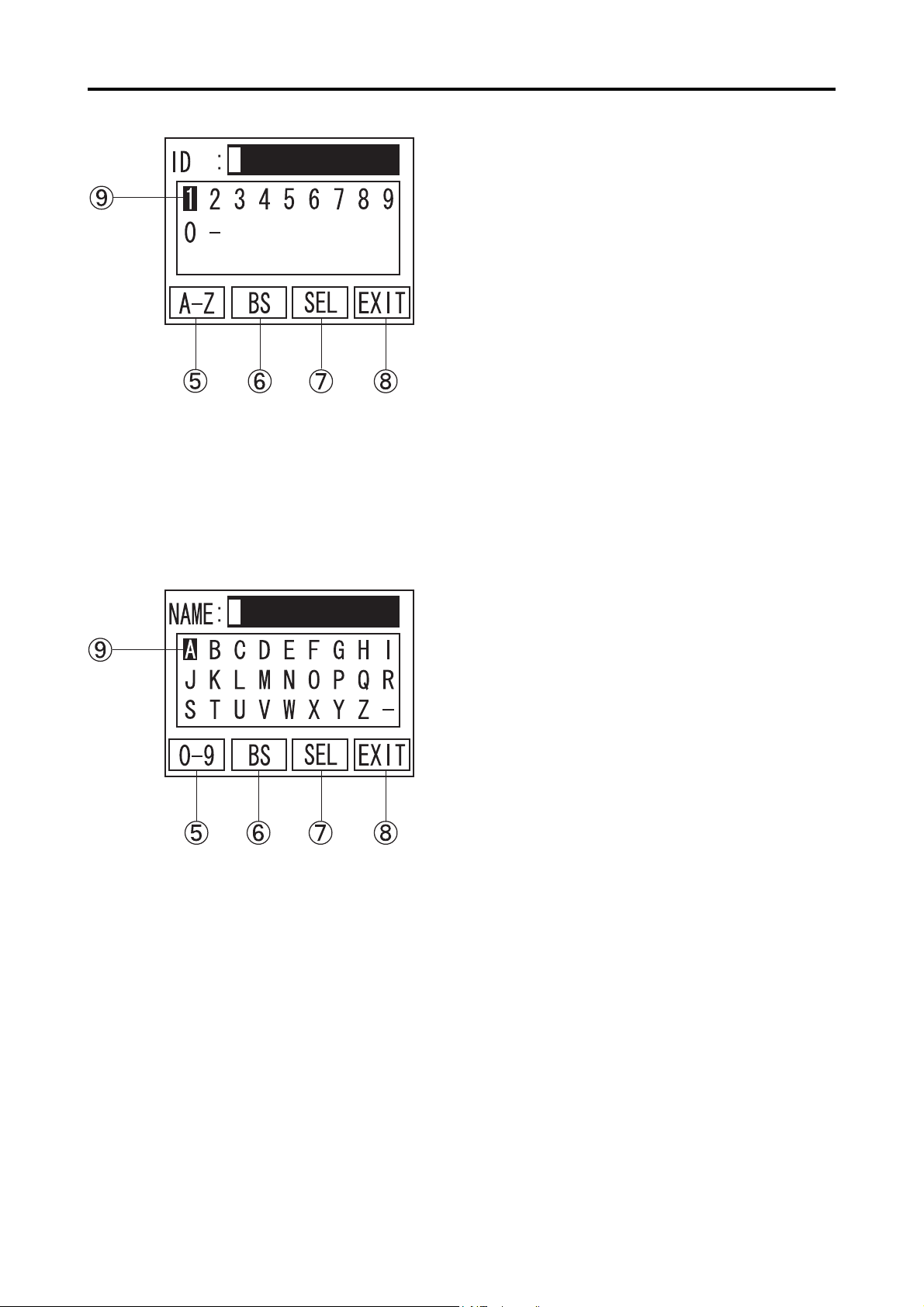
3) Press "W" or "X" keys to move Cursor I to
the figures or letters, you wish to input. (Fig. 3)
Then, press SEL G to enter selected character.
(Fig. 3)
4) Press F1 key E to switch over input mode be-
tween figures and letters.
5) Press F2 key F to enter Back Space.
6) When Patient ID type in completed, press F4 key
H to go back to INDEX Screen (Fig. 1).
(Fig. 4)
3-10
7) Repeat the above procedure again to type in Pa-
tient name. (Fig.4)
3.3 Adjustment and Setting
Page 27
b) The eye to be measured
c) Corneal ultrasound velocity
Select Right eye or Left eye, to be measured.
Press F1 key A to switch over Right and Left dis-
play.
d) Listed data on screen
Ultrasound Velocity can be changed by going into
setting Menu. Please refer to "3.7.3 c) corneal Ultra-
sound Velocity (VELOCITY)" for details.
One, out of three, data type A can be selected as
listed data type. The three options are as follows.
AVERAGE
The mean value of each data box is listed.
LATEST
The last measurement for each data box is listed.
MINIMUM
The minimum value of all measurements for
each data box is displayed.
Please refer to "3.7.3 d) Setting of the type of display
data (DATA SELECTION)" for details.
3.3 Adjustment and Setting
3-11
Page 28

3.4 Preparation for measurement
3.4.1 Calibration of the Probe
yy
y In case of using the disposal tip probe, be sure to calibrate
yy
it with the disposal tip attached.
yy
y Be sure the tip of the Probe is dry and free from any water,
yy
before calibrating probe.
yy
y In case of using the disposal tip Probe, the disposal tip is
yy
automatically detected by SP-100. Therefore, no measure-
ment can be made without calibrating the Probe.
1) This instrument automatically calibrates the
Probe, when the power is turned on and the
probe is plugged. (Fig. 1)
(Fig. 1)
(Fig. 2)
2) When the probe is removed or the tip of the
probe is removed with disposable tip probe, the
instrument automatically detect the abnormal
situation and shows CALIBRATION screen
(Fig.2).
Check the connection of the probe and tip, then
press "W" for re-calibration.
3-12
3.4 Preparation for measurement
Page 29

3.4.2 Operation Check
The test piece included in the accessory box is
supplied for checking the operation of the instru-
ment. The measurement result varies, depending
on room temperature and other factors. The in-
strument cannot test its accuracy by measuring
this test piece.
1) Go to Pachy screen
2) Place the test piece into water until it covers
over the piece. Apply the Probe into either of
the dents on the piece perpendicularly, so the
instrument will start measurement automati-
cally.
3.4.3 Measurement Preparation for Patient
Patients' cooperation is necessary for smooth op-
eration.
Prior to measurement, explain about the purpose
of examination and measuring procedures to the
Patient so as not to give fears, but to relax in a
good mood.
1) Review the settings and calibrate the Probe or
check the instrument, if necessary.
2) Give eye-drops anesthesia to the eye to be mea-
sured. The patient should be seated with the
Back Rest or should lie on a bed.
3) If the eye seems to be dry or has little tears,
apply balanced salt solution to avoid dry sur-
face of cornea.
3.4 Preparation for measurement
3-13
Page 30

3.5 Measurement
The Probe should always be disinfected before its use.
The disposal tip should be disinfected before its use.
Do not use the Probe with its tip damaged. This causes inaccurate
measurement as well as the corneal damage for patients.
yy
y The corneal ultrasound velocity has direct influence on
yy
measurement results. Before taking measurement, make
sure that the appropriate velocity is set for measurement.
Please refer to "3.7 Menu" for details.
yy
y In case the corneal surface is dry, apply balanced salt so-
yy
lution for moisture.
yy
y Auto Measurement Function is an assistant function to
yy
make measurement easy, but does not clinically determine
actual diagnosis. In case of applying results, the examiner
should always evaluate them for use.
3-14
3.5 Measurement
Page 31

3.5.1 Single measurement
a) Measuring procedures
(Fig. 1)
1) Place the probe perpendicularly to the corneal
surface, where the thickness needs to be taken.
2) When the measuring conditions meets a cer-
tain level, the instrument automatically starts
taking measurement (Fig.1).
The instrument makes beep, when measurement
has been taken into the unit.
3) When twenty measurements have been taken,
the instrument sounds two "beeps" to announce
the measurements are completed.
(Fig. 2)
4) Move the Probe away from cornea, so the cursor A will move to next memory in order to be
ready for another measurement (Fig.2). 20 mea-
surements will not be necessary to complete it
in one place. The instrument completes the
measurement in the position, when the probe
is taken away and it beeps twice.
5) Repeat the measurement process to fill 8 memo-
ries with data. When Retake measurement on cer-
tain memories with overwriting, go to EDIT screen
to move highlighted memory, then back to Pachy
screen to take the measurement.
6) For the measurement of the other eye, press F1
key B to switch between Right and Left.
3.5 Measurement
3-15
Page 32

3.5.2 Delete Each Data Reading
(Fig. 1)
When the data is once deleted, it can never be re-
called and the deleted data will be lost. Please pay
special attention, not to delete necessary measure-
ments.
1) Press F3 key A on Pachy screen (Fig. 1) to
change screen into EDIT (Fig. 2).
(Fig. 2)
2) Press "W" or "X" to move Cursor B to highlight
the measurement that should be deleted.
3) Press F3 key C and keep holding it for a while,
until the instrument sounds "beep" to complete
deleting.
3-16
3.5 Measurement
Page 33

3.5.3 Delete Data (Eye by eye or patient by patient)
When the data is once deleted, it can never be recalled and the
deleted data will be lost. Please pay special attention, not to
delete necessary measurements.
a) Delete Data of one eye (Retaking measurements of the same eye)
Delete all data on screen.
1) Press F1 key A in Pachy Screen (Fig. 1) to se-
lect which eye data should be deleted.
(Fig. 1)
(Fig. 2)
2) Press F3 key B to change screen to EDIT (Fig.
2).
3) Press F2 key C and keep holding it for a while,
until the instrument sounds "beep" to confirm
all the data on screen has been deleted.
3.5 Measurement
3-17
Page 34

b) Delete Data of both Right and Left Eye including patient information (Ready for new patient
measurement)
Delete all the data on both eyes, as well as Patient
ID and name.
Press F4 key A on pachy screen and keep holding
it for a while, until the instrument sounds "beep" to
confirm all the data has been deleted.
3-18
3.5 Measurement
Page 35

3.6 Printout
3.6.1 How to Printout the data
yy
y Prior to Printout, make sure the proper paper
yy
is set correctly and the paper remains suffi-
ciently.
yy
y Please be careful not to cut yourself, when cut-
yy
ting the paper by hand.
Press the PRINT Key for operation in the Measure-
ment Standby Screen (Fig. 1), the EDIT Screen (Fig.
2), or the DATA COMMUNICATION, SEND Screen
(Fig. 3) for Printout of measured data.
(Fig. 1)
(Fig. 2)
(Fig. 3)
3.6 Printout
3-19
Page 36

3.6.2 Description of Printout
a) Standard mode
A Time/Data
B ID number
C Patient's name
D Corneal Ultrasound Velocity
E Type of display data
F Eye to be measured
G Measured data
H Average of measured data
I SD(Standard Deviation) of measured data
b) Simple mode
Patient Name and Breaking Line are out of printout
paper on Simple Mode.
3-20
3.6 Printout
Page 37

3.6.3 IOP Calculation Printout
a) Standard mode
A Time/Data
B Patient ID
C Patient's Name
D Corneal Ultrasound Velocity
E Right/Left
F Eye to be measured
G Measured data
H Measured data average
I Measured data SD (standard deviation)
J Parameter 1
K Parameter 2
L CCT (Central Corneal Thickness)
M IOP (Inter Ocular Pressure)
b) Simple mode
N Adjusted IOP
D ~ I will not be printout, when there is no mea-
sured data.
Only Time/Date, Patient ID, Adjusted IOP related data
will be printout by Simple mode.
3.6 Printout
3-21
Page 38

3.7 Menu
3.7.1 Description of the Screen display
A TIME-DATE
Date and time are set.
B SOUND
The sound volume is set.
C VELOCITY
The corneal ultrasound velocity is set.
D DATA SEL
The mode of display data is set.
E PRINTOUT
The print mode is set.
F Pachy (F 1)
The screen is changed to the Measurement Standby Screen.
G IOP (F 2)
Move to IOP Calculation Main Screen.
H SEL (F 3)
The Highlighted function is selected.
I EXIT (F 4)
3-22
The screen is returned to the EDIT Screen.
3.7 Menu
Page 39

3.7.2 Operation for the MENU Screen
(Fig. 1)
1) Press F3 Key A in the Measurement Standby
Screen, to change the screen to the EDIT Screen
(Fig. 2).
2) Press F4 Key B in the EDIT Screen, to change
the screen to the MENU Screen (Fig. 3).
(Fig. 2)
(Fig. 3)
3) Press " W " or " X " of the Operating Panel and
next press F3 Key C by aligning the Select Cur-
sor to the item to be set, to change the screen for
each item.
Press F1 Key D to return the screen to the Mea-
surement Standby Screen (Fig. 1).
3.7 Menu
3-23
Page 40

3.7.3 Operating procedures of the Menu Screen
a) Setting of date and time (TIME/DATE)
(Fig. 1)
1) Press "W" or "X" of the Operation Panel, to
align the Cursor to "TIME/DATE". Next press
F3 Key A to change the screen to the Time/Date
Screen (Fig. 2).
Press F4 Key B to return the screen to the EDIT
Screen.
2) Press "W" or "X" of the Operation Panel, to
(Fig. 2)
align the cursor C to YEAR. Next, press F3 key
D to change the screen to the Setting Screen (Fig.
3).
Pressing of the EXIT key E returns the screen
to the MENU Screen (Fig. 1).
3) Press "W" or "X" of the Operation Panel, to
increase or decrease the dominical year at the
cursor position. Pressing F3 key F after the
dominical year has been set returns the screen to
the Setting Screen (Fig. 2).
Set the other items in a similar manner.
(Fig. 3)
3-24
Pressing F4 Key E returns the screen to the Date
and Time Setting Screen (Fig. 2).
3.7 Menu
Page 41

b) Sound volume (SOUND)
(Fig. 1)
1) Press " W " or " X " of the Operation Panel, to
align the cursor to "SOUND". Next, press the
SEL key A to change the screen to the Sound
Volume Setting Screen (Fig. 2).
Pressing F4 key B returns the screen to the EDIT
Screen.
2) Press " W " or " X " of the Operating Panel, to
increase or decrease the sound volume.
(Fig. 2)
Pressing F4 Key C returns the screen to the
MENU Screen (Fig.1).
x "-": No SOUND
x "X": Small SOUND
x "XX": Medium SOUND
x "XXX": Large SOUND
3.7 Menu
3-25
Page 42

c) Corneal Ultrasound Velocity (VELOCITY)
(Fig. 1)
1) Press "W" or "X " of the Operating Panel to
align the cursor to "VELOCITY".
Next press F3 Key A to change the screen to the
Corneal Ultraound Velocity Screen (Fig. 2).
Pressing F4 Key B returns the screen to the EDIT
Screen.
2) Pressing "W" or "X " of the Operating Panel in-
creases or decreases the sound velocity.
(Fig. 2)
[Input range]
Corneal ultrasound velocity: 1,400 to 2,000
m/s
Pressing F4 Key C returns the screen to the
MENU Screen (Fig. 1).
3-26
3.7 Menu
Page 43

d) Setting of the type of display data (DATA SELECTION)
1) Press "W" or "X " of the Operating Panel to
align the cursor to "DATA SEL".
Next press F3 A and change the screen to the
Setting Screen (Fig. 2) for the type of data to be
displayed.
Pressing F4 Key B returns the screen to the EDIT
(Fig. 1)
(Fig. 2)
Screen.
2) Press "W" or "X" of the Operating Panel to align
the cursor to the type of data desired to be dis-
played.
Pressing F4 Key C returns the screen to the
MENU Screen (Fig. 1).
(Fig. 3)
If measured data are left remaining in the screen,
the type of display data cannot be changed.
Resetting of the type of display data shall be
made after deleting the data by returning the
screen to the Measurement Standby Screen (Fig.
3) and long pressing F4 Key D.
3.7 Menu
3-27
Page 44

e) Print mode
(Fig. 1)
1) Press "W" or "X" of the Operation Panel, to
align the cursor to "PRINTOUT". Next, press F3
key A to change the screen to the Printout Setting
Screen (Fig. 2).
Pressing F4 key B returns the screen to the EDIT
Screen.
2) Press "W" or "X" of the Operation Panel, to
align the cursor to "STANDARD" or
(Fig. 2)
"SIMPLE". (See 3.6.2 for the description.)
Pressing F4 key C returns the screen to the
MENU Screen (Fig. 1).
3-28
3.7 Menu
Page 45

3.7.4 IOP Calculation
(Fig. 1)
1) Press F2 A to change the screen to IOP calcula-
tion (Fig.2).
2) Press F1 B to select either RIGHT/LEFT eye
data should be calculated C.
(Fig. 2)
(Fig. 3)
3) Press F2 D to change the screen to Tonometry
Input (Fig.3).
Press F1 E to move cursor F between RIGHT
and LEFT.
Input the Tonometry for IOP Calculation formula.
Press "W" or "X" to select the figures and press
F3 G to enter.
[Tonometry Input Range] : 1 ~ 60 mm
Hg : 133~7998Pa
3.7 Menu
3-29
Page 46

(Fig. 4)
Press F4 H to select the screen to IOP Calcula-
tion (Fig.4)
3) Press F3 I to change the screen to CCT Input
(Fig.5) Average of total measurement data will be
automatically input, when there is any data for cal-
culation.
Press F1 J to move cursor K between RIGHT
and LEFT.
(Fig. 5)
(Fig. 6)
Press "W" or "X" to select the figures and press
F3 L to enter.
[CCT Input Range] : 0 ~ 1,500 µm
4) Press F4 M to change the screen to PARAM-
ETERS INPUT (Fig.6)
Press F1 N to move highlighted cursor between
Parameter 1 P and 2 Q.
Press "W" or "X" to select the figures and press
F3 L to enter Parameter 1 P and 2 Q.
3-30
[Parameter Range]
Parameter 1 : 0 ~ 1,500 µm
Paramater 2 : 0 ~ 1.000 µm
3.7 Menu
Page 47

(Fig. 7)
5) Press F4 R to change the screen to IOP Calcula-
tion (Fig.7) to show calculation result S.
6) Press F4 T to go back to Main MENU (Fig.1).
3.7 Menu
3-31
Page 48

3.8 Sending and receiving data
Connect the instrument to the equipment which
complies with the IEC06-1 or the IEC950 and of
which power source is isolated with the dielectric
transformer, by using the serial communication
cable.
This instrument can send and receive data to and from the
external equipment, by using the serial communication cable.
3.8.1 How to connect the serial communication cable
The insertion direction of the connector is speci-
fied. Securely insert the connector in specified
direction without looseness.
The serial communication cable used for this instrument is of
a female type. In case of connecting this connector with the
personal computer, connect the male/female adapter to the
male/female cable or the female/female cable in accordance
with the following procedure.
1) Connect the serial communication cable connector B to the serial communication cable terminal A and secure these parts with the fixed
screw C.
[Positions of D-sub 9 pins]
Pin No. Signal name
1 2 RxD
3 TxD
4 DTR
5 SG
6 DSR
7 RTS
8 CTS
9 -
It is noted that No. 4 and No.6 pins and No.7 and
3-32
No. 8 pins are shorted inside of the instrument.
3.8 Sending and receiving data
Page 49

3.8.2 Setting of communication conditions
(Fig. 1)
1) Press F2 Key A to change the screen to the IN-
DEX Screen. (Fig. 2)
2) Press F4 Key B to change the screen to the DATA
COMMUNICATION Screen. (Fig. 3)
(Fig. 2)
(Fig. 3)
3) Use "W" or "X" keys to select "SETUP" to go to
the COM Set-up screen (Fig. 4).
Press F4 key D to go back to INDEX screen
(Fig. 2).
3.8 Sending and receiving data
3-33
Page 50

4) Press "W" or "X" of the Operating Panel to set
the BAUD RATE. The baud rate is selective from
three stages of 9600, 19200, and 38400. Press
F1 key E to set as 38400 (default).
When F2 Key F is pressed, the screen will be
(Fig. 4)
(Fig. 5)
changed as shown in Fig. 5. The Machine number
can also be set by pressing "W" or "X" of the
Operating Panel.
When F2 Key is pressed again, the screen will be
returned to the screen shown in Fig. 4.
[Communication Setup]
BAUD RATE: 9600, 19200, 38400
DATA BIT: 8BIT (Fixed)
PARITY: NONE (Fixed)
STOP BIT: 1BIT (Fixed)
FLOW: NONE (Fixed)
MACHINE: 0 to 99
Press F4 key I to go back to DATA COMMUNICATION screen (Fig.3).
3-34
3.8 Sending and receiving data
Page 51

3.8.3 Data Export
(Fig. 1)
Please refer to "3.9 Data Management with TOMEYLink (Elec-
tronic Medical Record Support System)" to send Data to
TOMEYLink.
1) Press "W" or "X" of the Operating Panel in the
DATA COMMUNICATION Screen and align the
cursor to "SEND".
Press F3 Key A to change the screen to the Data
Communication Screen (Fig. 2).
(Fig. 2)
2) Press F2 Key B to change the screen to the Data
Confirmation Screen (Fig.3)
Make sure in this screen that the serial commu-
nication cable is connected to the external
equipment and press F3 Key D, so the data will
be sent to the external equipment. (It should be
noted that no data can be sent unless related ID
has been entered.)
(Fig. 3)
3.8 Sending and receiving data
3-35
Page 52

(Fig. 4)
3) "NOW COMMUNICATING" is displayed while
data is being sent. (Fig. 4) When F4 Key E is
pressed, while data is being sent, the process of
sending data is cancelled.
4) When data is properly sent, "SENT COM-
PLETE!" is displayed. (Fig. 5) Then, press F4
F to return the screen to the Data Communica-
tion Screen (Fig. 2).
(Fig. 5)
3-36
3.8 Sending and receiving data
Page 53

3.8.4 Data Receiving
(Fig. 1)
Please refer to "3.9 Data Management with TOMEYLink (Elec-
tronic Medical Record Support System)" to send Data to
TOMEYLink.
1) Make sure before receiving data that there is no
data left in the Data Standby Screen. Then, change
the screen to the Data Communication Screen (Fig.
2). If any data is left remaining in the screen, delete such data by long pressing F4 Key A.
(Fig. 2)
2) Next press "W" or "X" of the Operating Panel
and align the cursor to "RECEIVE". Then press
F3 Key B to change the screen to the Data Re-
ceiving Screen (Fig. 3).
3) When F3 Key C is pressed, the screen will be
ready for receiving data. Then, operate the data
sending side to send data.
(Fig. 3)
3.8 Sending and receiving data
3-37
Page 54

(Fig. 4)
4) The screen displays "NOW COMMUNICAT-
ING" while in the process of receiving data.
(Fig. 4) When F4 Key E is pressed, receiving
data is cancelled.
5) When data is properly received, "RECEIVED
COMPLETE!" is displayed.(Fig. 5)
Then press F4 F to return the screen to the Data
Communication Screen (Fig. 2).
(Fig. 5)
3-38
3.8 Sending and receiving data
Page 55

3.9 Data Management with
(Electronic Medical Record Support System)
Please refer to Operation Manual of TOMEYLink (Electronic
Medical Record Support System) to setup TOMEYLink soft-
ware and LAN adapter (LA-100).
Patient ID is necessary in order to send the data outside the unit
by TOMEYLink. Optional Key-Pad is used in this manual to ex-
plain how to input Patient ID.
SP-100 must be connected with external
devices,complied with IEC601-1 Standard or the
devices complied with IEC950 Standard and elec-
trically insulated by insulation transformer.
3.9.1 Patient Data Receiving
(Fig. 1)
1) On Main Screen (Fig.1), press F2 key A to go
to INDEX screen (Fig.2).
2) Press F4 key B to go to DATA COMMUNI-
CATION (Fig.3).
(Fig. 2)
3.9 Data Management with TOMEY Link
3-39
Page 56

(Fig. 3)
3) Press "W" or "X" key to move the cursor to RE-
CEIVE.
Press F3 key C to go to Data Receiving (Fig.4).
4) When F3 key D is pressed, data receiving will be
ready. Input Patient ID through Key pad, connect-
ing with LAN adapter (LA-100).
Press F4 key E to go back to DATA COMMU-
NICATION (Fig.3).
(Fig. 4)
Patient ID, typed in SP-100 has nothing to do
with TOMEYLink Patient ID. TOMEYLink Pa-
tient ID will always have priority to register data
on TOMEYLink. Please note that the ID on SP-
100 will be ignored.
5) "NOW COMMUNICATING" will be displayed,
while SP-100 is receiving data (Fig.5). Press F4
key F to cancel receiving data.
(Fig.5)
3-40
3.9 Data Management with TOMEY Link
Page 57

(Fig. 6)
6) When data is properly received, RECEIVED
COMPLETE! is displayed (Fig.6). When there is
no registered patient on TOMEYLink, according
to input ID, only the ID will be received. Press F4
key G to go back to DATA COMMUNICA-
TION (Fig.3).
7) Press F1 key H to return to the Measurement
Screen (Fig.1) and start taking measurement.
Patient Data can also be received, after taking mea-
surement. Please follow the instruction 2), after
taking measurement.
3.9.2 Data Sending
(Fig. 1)
(Fig. 7)
1) Press "W" or "X" button to move cursor to SEND
on DATA COMMUNICATION (Fig.1). Press
F3 key A to go to DATA SENDING screen
(Fig.2).
3.9 Data Management with TOMEY Link
3-41
Page 58

2) Press F2 key B to switch screen from DATA
SENDING (Fig.2) to DATA CONFIRMATION
(Fig.3).
Make sure Serial Communication Cable is prop-
erly connected to external device. Press F3 key
C to send data to TOMEYLink. When ID is
(Fig. 2)
(Fig. 3)
missing, whole data will not be sent.
Press F4 key D to go back to DATA COMMU-
NICATION (Fig.1).
3) "NOW COMMUNICATING" is displayed, while
data is sent (Fig.4). Press F4 key E to cancel
sending data.
(Fig. 4)
(Fig. 5)
3-42
4) When data is properly sent, SENTCOMPLETE!
is displayed (Fig.5). Press F3 key F to go back
to DATA SENDING screen (Fig.2).
3.9 Data Management with TOMEY Link
Page 59

3.10 Battery
Please use the battery only specified for SP-100. The use of wrong type
may cause Heating/Fire/Explosion of the battery and main unit.
yy
y After the battery has been charged, pull off
yy
the AC Adapter from the instrument. If the
battery is left as being connected to the instru-
ment for long time, the service life of the bat-
tery may be affected.
yy
y This instrument is enclosed with its exclusive
yy
battery; therefore, it can be used without the
AC Adapter as connected.
3.10.1 Battery charge balance
The remaining amount of battery charge is displayed in the
Monitor Screen, which is displayed in the following two steps.
: Sufficient charge left in the battery
: Less charge left in the batter
(Battery Recharging is necessary)
Recharge the battery if the charge level becomes low.
3.10 Battery
3-43
Page 60
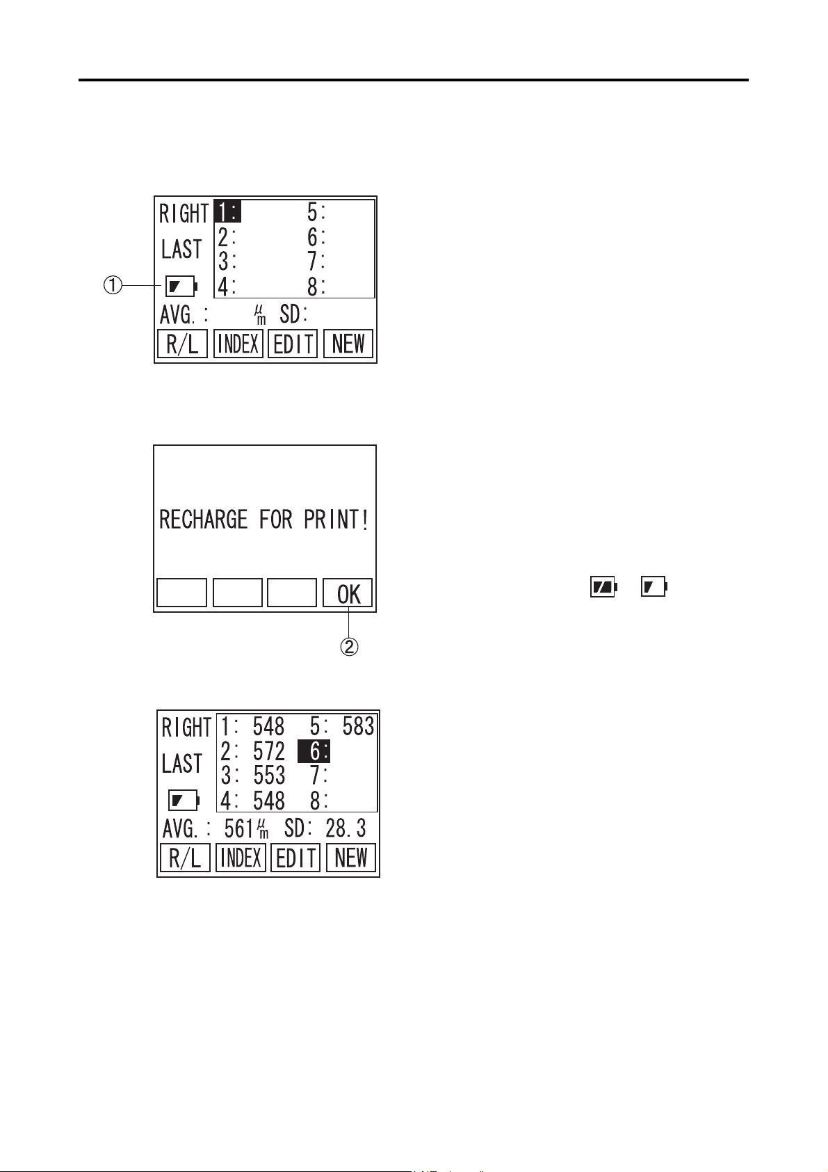
3.10.2 Low Battery Warning
(Fig. 1)
1) When capacity of the battery becomes low A,
SP-100 screen starts blinking and beeping (Fig.1).
Under this condition, the unit shuts down after 10
minutes of non-operating time, automatically.
Within 10 minutes, the battery needs to be charged
or measured data will be lost. Auto Power Off
waiting time is 3 minutes, but it will be extended to
10 minutes, when the battery is low, in order to
keep a certain time to start recharging the unit.
When the unit is powered by AC adapter, it starts
charging battery, then blinking and beeping stop
automatically.
2) When the battery is low A, built-in printer becomes out of service. When PRINT is pressed, a
warning (Fig.2) comes up on screen. Press F4 key
(B) to go back to main screen.
(Fig. 2)
(Fig. 3)
If the measured data is on screen (Fig.3), when
battery icon becomes to , printout is
available only once within 9 minutes. After 9
minnutes, since the battery becomes low or printout is provided once, the printer becomes out of
service and a warning (Fig.2) comes up, when
PRINT is pressed.
3-44
3.10 Battery
Page 61

3.10.3 Charge indicator
3.10.4 How to Install / Uninstall Battery
The charge indicator A on the Operating Panel lights
up, while the battery is being recharged. When the
charge indicator light goes off (Full Charged), discon-
nect the AC Adapter from the instrument.
Please pay special attention not to disconnect the battery
cable.
Please be careful not to cut the battery cables by putting
them between main unit and its cover, pulling them hard
or carrying the battery by holding only these cables.
1) Remove the Screw on backside of the unit A, then
remove the battery cover B .
2) Unplug the Battery Connector C carefully with
tweezers. Then, remove the battery D slowly from the
unit.
3) Connect the new battery D and plug the connec-
tor carefully.
4) Place the battery cover back and tighten the screw
A.
5) Please refer to “5.5 Precautions for disposal of
packing materials” on this book, for battery disposal.
3.10 Battery
3-45
Page 62

3.10.5 Lifetime of rechargeable battery
The battery, built-in the instrument, keeps 85% of its capacity
even after 500 times recharge and discharge under 25 degree
Celsius room temperature.
Since any battery has its lifetime, replace with new battery,
when its discharging time is getting shorter than it used to be.
3.10.6 Expected operating time of hours
The battery enclosed in the instrument is serviceable for the fol-
lowing operating time with its fully charged condition provided in
its initial stage.
3 minutes measurement for one Patient, without printout:
Approx. 6 hours.
3 minutes measurement for one Patient with printouts for
both eyes: Approximately 4 hours.
The above operating time is only an assumed measure, which
varies upon the using environments and conditions.
3-46
3.10 Battery
Page 63

4. REFERENCE TECHNICAL
INFORMATION
4.1 How to calculate corneal thickness
The corneal thickness is calculated in the following calcula-
tion by using the converted sound velocity in the cornea.
4.2 Acoustic Output
4.2.1 MI (Mechanical Index)
Tc =
MI is a parameter to show mechanical bio-effects of ultrasound.
Examples of mechanical
effects are motion (or streaming) around compressible gas bubbles
V x t
2
where,
Tc: Corneal thickness
V: Converted sound velocity in the cornea
t: Measuring time
4.2.2 TIS (Soft Tissue Thermal Index)
as ultrasound pressure
waves pass through tissues, and energy released in the collapse,
via cavitation, of
transient gas bubbles.
TIS is a parameter to show thermal bio-effects of ultrasound.
Thermal effect is
temperature rise of tissue by ultrasonic exposure.
4.1 How to calculate corneal thickness
4-1
Page 64

This page is left intentionary blank.
4-2
Page 65

5. MAINTENANCE AND INSPECTION
5.1 Warranty
One-Year Limited Warranty
The seller warrants this product to be free from defects in material and work-
manship under the normal use of this product for one (1) year or other term
complying with local regulations from the date of invoice issued by Seller to the
original purchaser.
Lamps, paper and other consumable items shall not be covered by this war-
ranty.
This warranty also shall NOT apply if the product has not been installed, oper-
ated or maintained in accordance with the OPERATOR MANUAL of Tomey
Corporation (here in after called "Tomey"). Neither seller not Tomey shall be
liable for any damages caused by purchaser's failure to follow instruction for
proper installation, use and maintenance of product.
This warranty is only applicable to the new product and DOES NOT cover
any damage resulting from or caused by accident or negligence, abuse, misuse,
mishandling, improper modification of this product, by persons other than per-
sonnel duty authorized by Tomey, not to a product whose serial number or
batch number is removed, altered or effaced.
THIS WARRANTY IS EXPRESSLY IN LIEU OF ANY AND ALL OTHER
WARRANTIES, EXPRESS OR IMPLIED (INCLUDING SPECIFICALLY,
WITHOUT LIMITING THE GENERALITY OF THE FOREGOING, ALL
WARRANTIES OF MERCHANTABILITY AND FITNESS FOR A PAR-
TICULAR PURPOSE), AND ALL OTHER OBLIGATION AND LIABIL-
ITY ON THE PART OF SELLER AND TOMEY. NEITHER SELLER NOR
TOMEY SHALL BE LIABLE FOR INCIDENTAL, CONSEQUENTIAL
OR SPECIAL DAMAGES UNDER ANY CIRCUMSTANCES OR FOR
MORE THAN REPAIR, REPLACEMENT OR REFUND OF THE PUR-
CHASE PRICE OF DEFECTIVE GOODS.
5.1 Warranty
5-1
Page 66

5.2 Routine maintenance
5.2.1 Measurement Probe
yy
y Be sure to hold the connector of the Probe cable to disen-
yy
gage the Probe from the instrument. Do not pull the cord
itself, which may cause to damage the cord or to ruin its
power connection.
yy
y Do not touch the connector, or the Probe may be damaged.
yy
yy
y Before applying the probe to patient, please make sure
yy
there is no damage, such as crack or split, on the probe tip.
yy
y Please make sure there is no loose connector nor discon-
yy
necting cable.
a) Cleaning
yy
y Use sanitary cotton for cleaning of the eye contacting part
yy
of the Probe not to damage.
yy
y Do not pull the cord of the Probe while cleaning.
yy
yy
y Do not wet the connector contacting part of the Probe when
yy
cleaning.
z For cleaning of the Probe, wipe stains with sanitary cotton ab-
sorbed with ethanol for disinfection and then clean it with water
soaked cloth.
z Completely remove water from the Probe after cleaning.
5-2
5.2 Routine maintenance
Page 67

b) Disinfection
z For disinfecting of the Probe, immerse the part of the Probe
within 15mm from the eye contacting part it in disinfection ethanol or 0.5% sodium hydrochloride water solution for 10 to 20
minutes and then wash it with distilled water and then dry sufficiently.
c) Sterilization
The use of the autoclave for sterilization of the Probe is pro-
hibited, or the Probe is severely damaged otherwise.
<Sterilization conditions>
EtO: Ethylene oxide 20%, and carbon dioxide 80%.
Sterilization temperature: 50±5C
Sterilization pressure: (9.8±0.98)×10000Pa
Sterilization time: 5±1 hr.
Aeration time: Pachymeter Probe....More than 10 hours
Disposable Tip.....20 sets of 30 minutes aeration
5.2 Routine maintenance
5-3
Page 68

5.2.2 Maintenance of the Main Unit
—
yy
y Do not use such organic solvents as thinners for cleaning
yy
the Main Unit of the instrument. Such organic solvents
may cause to damage the surface of the Main Unit.
yy
y Do not pull the power cord with an undue force.
yy
yy
y Care is to be taken not to touch the Probe connecting ter-
yy
minals.
z Remove stains from the instrument body by lightly rubbing the
surface with a piece of cloth which has been wetted with water
and then squeezed to remove water, and then by finishing with a
piece of dry cloth. In case of an excessive amount of stains, wet
the stained surface with a piece of cloth which has been wetted
with a diluted neutral agent. Furthermore, carefully wipe the surface with wet and dry cloths.
z Cleaning of stained monitor display is to be given by dry cloth. In
case of an excessive amount of stains, remove the stains with a
piece of cloth which has been wetted with a neutral cleanser and
tightly squeezed and furthermore by wiping wet and dry cloth.
z If the instrument is suspended for a while, disconnect the power
plug from the receptacle and place the dust cover over the instrument.
5-4
5.2 Routine maintenance
Page 69

5.3 Replacing of the printer paper
Replace the printing paper when the red lines appear on the both sides of
the roll paper, according to the following procedure.
Care is to be taken not to damage your hand with the paper
cutter, when opening and closing the Printer Cover.
1) Open the Printer Cover A to your side.
2) Remove the roll shaft for printing paper to be
replaced.
3) The printer paper is set by inserting and push-
(Fig. 1)
ing the paper end is inserted into the Printer
and, at the same time, pressing the PRINT Key
B. Make sure that the paper has been placed
with its face side turned on the printing side.
(Fig. 1)
4) Close the Printer Cover. Be sure to securely close
the Cover until it snicks. (Fig. 2)
5) Trim an extra length of paper.
(Fig. 2)
5.3 Replacing of the printing paper
5-5
Page 70

5.4 Storage
Store the instrument in a place where it is free of water, moisture and
chemicals.
Do not store the instrument in a place where it is subjected to high
temperature and high humidity and to any adverse influences that the
instrument may be exposed to dust, salts, and/or sulfur.
Minute care must be given not to cause the instrument with inclination,
vibration, or shock in routine operation and also when moving it from one
place to the other.
Do not store the instrument in or close to a place where chemicals or any
gases are stored or used.
z After using the Probe, clean and dry it. The protective cap should
be used for the Probe tip and stored in the Probe case.
z If the instrument is used after a long period of recession, make
sure that it functions properly and safely before use.
z Store the instrument under following Storing conditions to avoid
enshortening lifetime of built-in battery.
<Storing conditions>
Ambient temperature range: -20 to +45C
Relative humidity range: lower than 95%
5.5 Precautions for disposal of packing materials
yy
y Keep the containers and packing materials for future use.
yy
The packing container and cushion materials will be neces-
sary when moving or transporting the instrument.
yy
y Be sure to store the cushion materials when storing the
yy
container.
yy
y Disposing of the instrument and packing materials shall be
yy
done in accordance with the national and local environ-
mental rules and regulations.
yy
y This instrument is provided with the printed board using
yy
the lithium cells. It is specially noted the disposal of
lithium cells differ in local rules, so please follow your local
rules and regulations.
5-6
5.4 Storage 5.5 Precautions for disposal of packing materials
Page 71

6. TROUBLESHOOTING
Before presuming the instrument is disordered, check the following items. If
the following items do not correct the malfunction, consult with your local rep-
resentative for countermeasures.
Do not remove the outer cover of this instrument while in operation,
which will otherwise expose you to the direct high voltage.
yy
y Do not attempt to use the instrument for any purposes other
yy
than those specified in this Manual.
yy
y If the following items do not correct the malfunction, ask
yy
your local representative for inspection and repair.
z When the power is turned on, the Monitor Screen is not dis-
played.
Cause1
?
Remedy
Cause2
?
Remedy
Improper connection of the AC Adapter.
Check to see if the AC Adapter is securely connected to
the instrument and the power receptacle.
No power is supplied.
Check to see if the power is supplied to the power recep-
tacle.
6. TROUBLESHOOTING
6-1
Page 72

z No information is displayed in the Monitor Screen.
Cause1
?
Remedy
Cause2
?
Remedy
z The Monitor Screen is too dark to see.
Cause1
?
The Auto Power-off Function is in actuation, which automati-
cally turns the power of the instrument off if it does not con-
tinue operation for longer than 3 minutes.
Turn the power for the instrument on.
The switch for maintenance which is located at the rear side
of the instrument, is in its middle position (A).
Turn the power off, next return the switch to its middle
position (A), and then turn the power on.
The brightness of the Monitor is low.
Remedy
z No printout can be made.
Cause1
?
Remedy
Adjust the contrast of the Monitor Screen by turning
the Contrast Adjusting Volume. Turu the backlight LED ON,
if necessary. (2.3 Operation Keys)
The Printer paper has run out.
Check to see if the Printer paper is left sufficient for
printout.
Also check to see if the Printer paper is provided prop-
erly in such a manner that is specified in "5.4 How to
replace the Printer paper".
6-2
6. TROUBLESHOOTING
Page 73

z The Clock in the screen is in cease.
Cause1
?
Remedy
z The LED does not light.
Cause1
?
The INDEX Screen displayed after data measurement has
been made is shown.
In case the INDEX Screen displayed after data measure-
ment has been made is shown, the date and time when data
measurement was made are displayed in the screen.
The then time will be displayed by first deleting the data and
then displaying the INDEX Screen.
The Auto LED Off Function is in actuation, which auto-
matically turns the LED off if the instrument ceases op-
eration longer than one minute.
Remedy
z Ultrasound Velocity and Display Settings cannot be changed.
Cause1
?
Remedy
Pressing "W" and "X" keys in the Operation Panel con-
currently lights up the LED.
The measured data is stored in main memory.
Press New, CLR or DEL button to delete the stored data
to change current settings.
6. TROUBLESHOOTING
6-3
Page 74

<Measuring Function>
z "PROBE ERROR!" is displayed in the calibration of the Pachymeter
Probe given when the power is turned on.
Cause1
?
Remedy
z Measurement data is not stable or proper.
Cause1
?
Remedy
The connection of the Pachymeter Probe is not proper.
Properly connect the Probe, in accordance with the pro-
cedure specified in "3.2.1 a Connecting of the
Pachymeter Probe".
After the above, calibrate the Probe in the procedure
specified in "3.4.1 Calibration of the Pachymeter Probe"
or after once turning the power off and then rebooting
the the instrument.
The connection of the Pachymeter Probe is not proper.
Properly connect the Probe in accordance with the pro-
cedure specified in "3.2.1 a Connecting of the
Cause2
?
Remedy
Cause3
?
Remedy
Cause4
?
Remedy
Pachymeter Probe".
Using of the Probe is not proper.
Apply the Probe at a right angle to the corneal part to be
measured.
Setting of the conversion sound velocity has not been
properly set.
Make sure that the converted sound velocity has been set
properly.
The eye contact part of the Pachymeter Probe is damaged.
If such damage is found, stop measurement immediately
and consult with your local representative.
6-4
6. TROUBLESHOOTING
Page 75

Cause5
?
The Pachymeter Probe has not been properly calibrated.
Remedy
z No automatic measurement can be given.
Cause1
?
Remedy
Cause2
?
Clean the tip of the Probe and re-calibrate the Probe in the
procedure specified in "3.4.1 Calibrating of the Pachymeter
Probe" or once turn the power off, next reboot the instru-
ment, and the calibrate the Probe.
The Pachymeter Probe has not been properly calibrated.
Clean the end of the Probe and re-calibrate the Probe in
the procedure specified in "3.4.1 Calibrating of the
Pachymeter Probe" or once turn the power off, next
reboot the instrument, and the calibrate the Probe.
Surrounding noises have been interfered.
Remedy
Cause3
?
Remedy
Such noise sources as motor and laser surgery equip-
ment, if provided close to the instrument, must be moved
away from the instrument.
The eye contact part of the Pachymeter Probe is dam-
aged.
If so damaged, promptly discontinue measurement and
consult with your local representative.
6. TROUBLESHOOTING
6-5
Page 76

z Monitor sounds do not stop. Measurement data is taken when
measurement is not in process.
Cause1
?
Remedy
z Monitor sound is not made.
Cause1
?
Remedy
The tip of the Pachymeter Probe is wet with water.
Remove the water from the tip of the Probe.
The sound volume is set as OFF.
Turn the Sound Volume to a position other than OFF, in
accordance with "3.10.2 Sound Setting".
6-6
6. TROUBLESHOOTING
Page 77

7. SPARE PARTS AND OPTIONAL PARTS
The following spare parts and optional parts are available upon
ordering to your Tomey local distributor or representative.
7.1 Spare parts
z Printer paper
Specify your order article as "Printer paper for SP-100 "
when you order.
7.2 Optional parts
z Pachymeter Probe (Standard Probe)
Specify your order part as "Standard Pachymeter Probe
for SP-100" when you order.
z Disposal tip type Pachymeter Probe
Specify your order part as "Disposal tip type Pachymeter
Probe for SP-100" when you order.
z Disposal tip
Specify your order part as "Disposal tip for SP-100" when
you order.
7. SPARE PARTS AND OPTIONAL PARTS
7-1
Page 78

This page is left intentionary blank.
7-2
Page 79

8. SPECIFICATIONS
8.1 Specifications
8.1.1 Measuring function
z Default Converted Ultrasound Velocity and Setting Range
Corneal Ultrasound Velocity : 1,640 m/s
z Measuring range
Corneal thickness
Standard Probe : 150 to 1,200µm
Disposal tip type Probe : 150 to 1,200µm
z Instrument accuracy
Measuring accuracy : ±5µm
z Minimum Display Unit : 1µm
8.1.2 Measuring Probe
z Probe type
Standard Probe : Solid type/45 with angle
Disposal tip type Probe : Solid type/45 with angle,
(1,400 to 2,000 m/s)
straight
8.1.3 Main unit
8.1.4 AC Adapter
8.1.5 Enclosed battery
z Transducer frequency : 20MHz±20%
z Printer : Enclosed thermal printer
z Monitor screen : STN liquid crystalline display panel, 2.7 inch
black and white
z Dimensions / Weight : 118(W)×207(D)×59(H)mm/530g
z Power Concumption : 23VA + less than 15%
z Power Voltage & Frequency : AC 120V 60Hz 30W
AC 230V 50Hz 125mA
z Manufacturer : Globtek, Inc.
z Product Name : WD24C2000LCP-N-MED
WD24C2000L1P-N-MED
z Battery : Lithium ion battery
Rated capacity 1,000mAh
Nominal voltage 3.7V
* The above specifications and exterior appearance may be revised for improved performances of
the instrument.
8.1 Specifications
8-1
Page 80

8.2 Ultrasound energy and other information
8.2.1 Influences of ultrasound energy on the human body
SP-100 Pachymeter is exclusively designed and built for ophthalmic use.
Do not use the instrument for any purposes other than ophthalmic use.
SP-100 Pachymeter, exclusively designed and built for ophthalmic
pachymeter purpose, is set at very weak ultrasound energy ap-
propriate for ophthalmic application. Minutes care should be taken
not to cause the Patient to be excessively exposed with ultra-
sound energy while measurement.
8.2.2 Ultrasound energy
Acoustic Output Reportimg Table (FDA)
0.23
0.15
0.44
19.98
0.05
0.075
8000
MI : the Mechanical index
Ispta3 : the derated spatial-peak temporal-average intensity.
Isppa3 : the derated spatial-peak pulse-average intensity.
pr : the peak rarefactional pressure.
17
12.71
0.021
19.92
0.05
0.065
0.065
0.19
0.18
28
26.21
0.021
19.89
0.05
0.065
0.065
0.075
8000
8-2
pr.3 : the deratad peak rarefactional pressure.
Wo : the ultrasonic power
fc : the center frequency
Zsp : the axial distance at which the reported parameter is measured.
x-6, y-6 : are respectively the in-plane(azimuthal) and out of plane(elevational)
-6dB dimensions in the x-y plane where Zsp is found
8.2 Ultrasound energy and other consumptions
Page 81

PD : the pulse duration
PRF : the puls repetition frequency
EBD : the entrance beam dimensions for the azimuthal and elevational planes
Acoustic Output Report (IEC60601-2-37)
Index label MI
Maximum index value
[Mpa]
pr,
P [mW]
Min.of [P
Zs
zbp
Associated
Zb
acoustic
Z at max.Ipi,
parameters
deq (zb)
fawf [MHz]
Dim of Aaprt [cm]
Td [us]
Other
Pr at max.Ipi [MPa]
information
Operating
control
conditions
Prr [Hz]
deq at max.Ipi
Ipa,
Control
(zs),Ita, (zs)]
[cm]
at max.MI [W / cm2]
Non-scan(Aaprt 1cm2)
0.15
0.44
NA
NA
NA
NA
NA
0.05
NA
19.9
X
Y
NA
NA
0.075
8000
0.45
NA
26.21
NA
TIS
2.005
0.0211
19.9
0.19
0.18
NA
NA
NA
NA
NA
NA
NA
NA
NA
NA
NA
NA
NA
10
-3
NA : Not Applicable
a : ACOUSTIC ATTENUATION COEFFICIENT
Aaprt : -12dB OUTPUT BEAM AREA
Deq : EQUIVALENT APERTURE DIAMETER
deq : EQUIVALENT BEAM DIAMETER
fawf : ACOUSTIC WORKING FREQUENCY
Ipa : PULSE-AVERAGE INTENSITY
Ipa, a : ATTENUATED PULSE-AVERAGE INTENSITY
Ipi : PULSE-INTENSITY INTEGRAL
Ipi, a : ATTENUATED PULSE-INTENSITY INTEGRAL
MI : MECHANICAL INDEX
P : OUTPUT POWER
Pa : ATTENUATED OUTPUT POWER
Pr : PEAK-RAREFACTIONAL ACOUSTIC PRESSURE
Prr : PULSE REPETITION RATE
TIS : SOFT-TISSUE THERMAL INDEX
td : PULSE DURATION
X,Y : -12dB OUTPUT BEAM DIMENSIONS
8.2 Ultrasound energy and other consumptions
8-3
Page 82

z : DISTANCE FROM THE SOURCE TO A SPECIFIED POINT
zb : DEPTH FOR TIB
zbp : BREAK-POINT DEPTH
zs : DEPTH FOR TIS
8.3 Noise Generation
This instrument makes monitoring sounds at the following occa-
sions.
When turning the power on.
When Printout
When operating various keys and buttons
When taking measurement (such as taking data)
8.4 Operating Environment
This instrument must be used under following environment.
<Working Environment>
Ambient temperature range : +10 to 40C
Relative humidity range : 3 0 to 75% non-condensing
Store the instrument under following Storing conditions to avoid
enshortening lifetime of built-in battery.
<Storage Condition>
Ambient temperature range : -20 to +45C
Relative humidity range : Less than 95%
8.5 Conformed Standard
IEC60601-1 : 1988
Amendment 1 : 1991
Amendment 2 : 1995
8-4
IEC60601-1-2 : 2001
IEC60601-2-37 : 2001
8.3 Nose Generation 8.4 Operating Environment 8.5 Conformed Standard
Page 83

Appendix:
Electromagnetic guidance
Caution: Medical electrical equipment.
EMC (Electro Magnetic Compatibility) must be considered before any medical electrical equipment is
installed or put into service. Follow the information in the accompanying documentation when installing
and operating the SP-100.
Caution: Portable or mobile RF communication equipment can effect Medical Electrical equipment.
Guidance and manufacturer's declaration -
electromagnetic emissions
The SP-100 is intended for use in the electromagnetic environment specified below.
The customer or the user of the SP-100 should assure that it is used in such an environment.
Emissions test
RF emissions
CISPR 11
RF emissions
CISPR 11
Harmonic emissions
IEC 61000-3-2
Voltage fluctuations/
flicker emissions
IEC 61000-3-3
Compliance
Group 1
Class B
Class B
Complies
Electromagnetic environment - guidance
The SP-100 uses RF energy only for its internal function.
Therefore, its RF emissions are very low and are not
likely to cause any interference in nearby electronic
equipment.
The SP-100 is suitable for use in all establishments,
including domestic establishments and those directly
connected to the public low voltage power supply network
that supplies buildings used for domestic purposes.
Table 201
8.5 Conformed Standard
8-5
Page 84

Guidance and manufacturer's declaration -
electromagnetic immunity
Table 202
The SP-100 is intended for use in the electromagnetic environment specified below. The customer or the
user of the SP-100 should assure that it is used in such an environment.
Immunity test
Electrostatic
Discharge(ESD)
IEC 61000-4-2
Electrical fast
transient/ Burst
IEC 61000-4-4
Surge
IEC 61000-4-5
Voltage dips, short
interruptions and
voltage variations
on power supply
input lines
IEC 61000-4-11
IEC 60601 test
level
± 6kV contact
± 8kV air
± 2kV for power
supply lines
± 1kV for
input/output
lines
± 1kV differential
mode
± 2kV common
mode
< 5 % U
T
(> 95 % dip in UT )
for 0,5 cycle
40 % U
T
(60 % dip in UT )
for 5 cycles
70 % U
T
(30 % dip in UT )
for 25 cycles
Compliance level
± 6kV contact
± 8kV air
± 2kV for power
supply lines
± 1kV for
input/output
lines
± 1kV differential
mode
± 2kV common
mode
< 5 % U
T
(> 95 % dip in UT )
for 0,5 cycle
40 % U
T
(60 % dip in UT )
for 5 cycles
70 % U
T
(30 % dip in UT )
for 25 cycles
Electromagnetic environment guidance
Floors should be wood, concrete or
ceramic tile. If floors are covered with
synthetic material, the relative
humidity should be at least 30%
Mains power quality should be that of
a typical commercial or hospital
environment.
Mains power quality should be that of
a typical commercial or hospital
environment.
Mains power quality should be that of
a typical commercial or hospital
environment. If the user of the SP-100
requires continued operation during
power mains interruptions, it is
recommended that the SP-100 is
powered from an uninterruptible
power supply or a battery.
Power frequency
< 5 % U
T
(> 95 % dip in UT )
for 5 sec
3 A/m
< 5 % U
T
(> 95 % dip in UT )
for 5 sec
3 A/m
(50/60 Hz)
magnetic field
IEC 61000-4-8
NOTE : UT is the a.c. mains voltage prior to application of the test level.
8-6
8.5 Conformed Standard
Power frequency magnetic fields
should be at levels characteristic of a
typical location in a typical
commercial or hospital environment.
Page 85

Guidance and manufacturer's declaration -
electromagnetic immunity
Table 204
The SP-100 is intended for use in the electromagnetic environment specified below. The customer or the
user of the SP-100 should assure that it is used in such an environment.
Immunity test
IEC 60601 test
level
Compliance
level
Electromagnetic environment - guidance
Portable and mobile RF communication
equipment should be used no closer to any part
of the SP-100, including cables, than the
recommended separation distance calculated
from the equation applicable to the frequency of
the transmitter.
Recommended separation distance
d =1.2
Conducted RF
IEC 61000-4-6
Radiated RF
IEC 61000-4-3
3 V rms
150kHz to 80MHz
3 V/m
80MHz to 2,5GHz
3 V
3 V/m
d =1.2
d =2.3
Where P is the maximum output power rating of
the transmitter in watts (W) according to the
transmitter manufacturer and d is the
recommended separation distance in meters (m).
Field strengths from fixed RF transmitters, as
determined by an electromagnetic site survey,
should be less than the compliance level in each
frequency range.
Interference may occur in the vicinity of
equipment marked with the following symbol:
80 MHz to 800 MHz
800 MHz to 2.5 GHz
b
a
Note1 : At 80MHz and 800MHz, the higher frequency range applies.
Note2 : These guidelines may not apply in all situations. Electromagnetic propagation is affected by
absorption and reflection from structures, objects and people.
a
Field strengths from fixed transmitters, such as base stations for radio (cellular/cordless) telephones and
land mobile radios, amateur radio, AM and FM radio broadcast and TV broadcast cannot be predicted
theoretically with accuracy. To assess the electromagnetic environment due to fixed RF transmitters, an
electromagnetic site survey should be considered. If the measured field strength in the location in which
the SP-100 is used exceeds the applicable RF compliance level above, the SP-100 should be observed to
verify normal operation. If abnormal performance is observed, additional measures may be necessary,
such as reorienting or relocating the SP-100.
b
Over the frequency range 150 kHz to 80 MHz, field strengths should be less than 3 V/m.
8.5 Conformed Standard
8-7
Page 86

Recommended separation distances between
portable and mobile RF communications equipment and the
SP-100
Table 206
The SP-100 is intended for use in an electromagnetic environment in which radiated RF disturbances are
controlled. The customer or the user of the SP-100 can help prevent electromagnetic interference by
maintaining a minimum distance between portable and mobile RF communications equipment
(transmitters) and the SP-100 as recommended below, according to the maximum output power of the
communications equipment.
Rated maximum output
power of transmitter
W
0.01
0.1
1
10
100
For transmitters rated at a maximum output power not listed above, the recommended separation distance
d in meters (m) can be estimated using the equation applicable to the frequency of the transmitter, where P
is the maximum output power rating of the transmitter in watts (W) according to the transmitter
manufacturer.
150 kHz to 80 MHz
Separation distance according to frequency of transmitter
m
80 MHz to 800 MHz
d =1.2
0.12
0.37
1.2
3.7
12
d =1.2
0.12
0.37
1.2
3.7
12
800 MHz to 2.5 GHz
d =2.3
0.23
0.74
2.3
7.4
23
NOTE 1 : At 80MHz and 800MHz, the separation distance for the higher frequency range applies.
NOTE 2 : These guidelines may not apply in all situations. Electromagnetic propagation is affected by
absorption and reflection from structures, objects and people.
8-8
8.5 Conformed Standard
Page 87

9. Index
INDEX
Disinfection 3-2, 5-3
disposal 5-6
Disposal Tip 3-3
Disposal tip 3-14, 7-1
A
AC Adapter 2-1, 3-2, 3-39, 6-1
AC adapter terminal 1-4
AC power adapter 1-5
Acoustic Output 4-1
Auto Measurement Function 3-14
Auto Power Off 3-4, 6-2
Average 3-7, 3-11, 3-20
B
Battery 3-7, 3-35, 3-39, 8-1
BAUD RATE 3-30
Biometry probe 1-3
C
calculation formula 1-5
CALIBRATION 3-6, 3-12
Charge indicator 2-2, 3-41
Cleaning 5-2
CLR (F2 key) 3-8
COM 3-29
Communication Setup 3-30
Contrast 1-4, 2-1, 6-2
converted sound velocity 6-4
Corneal thickness 4-1, 8-1
Corneal Ultrasound Velocity 3-9, 3-14, 3-20, 3-21, 3-
25, 8-1
Cursor 3-8, 3-16
D
D-sub 9 pins 3-28
DATA BIT 3-30
DATA COMMUNICATION 3-19, 3-29, 3-30, 3-31
DATA SEL 3-21, 3-26
DEL (F3 key) 3-8
Delete 3-17, 3-18
E
EDIT 3-7, 3-15, 3-16, 3-17, 3-26
EOG 5-3
ERROR 3-6
EXIT 3-21
Explosion 3-39
Eye to be measured 3-20
F
Fire 3-39
FLOW 3-30
Frequency 8-1
FUNCTION KEYS 2-2
H
Heating 3-39
I
ID number 3-20
INDEX 3-7, 3-9, 3-10, 6-3
Instrument Stand 2-1, 3-4
L
LATEST 3-11
LED 6-3
Low Battery 3-40
M
MACHINE 3-30
Maintenance switch 1-4, 2-1
Measured data 3-20
Measurement data 3-7, 3-8
Measurement Standby Screen 3-22
Measuring time 4-1
Memory card 1-3
MENU 3-22, 3-26
MENU (F4 key) 3-8
MI (Mechanical Index) 4-1
MINIMUM 3-11
INDEX
A-1
Page 88

N
NEW 3-7
NOW COMMUNICATING 3-32, 3-34, 3-36, 3-38
O
OPERATING PANEL 2-1
Optional parts 7-1
P
SOUND 3-21, 3-24
sound volume 6-6
Spare parts 7-1
Specifications 8-1
Standard Probe 7-1
Sterilization 5-3
STOP BIT 3-30
Storage 5-6, 8-4
Symbols 1-4
Pachy 3-8, 3-21
Pachy screen 3-7
Pachymeter Probe 3-2
Pachymeter probe terminal 1-4, 2-1
packing materials 5-6
PARITY 3-30
Patient ID 3-9, 3-10
Patient name 3-9, 3-10, 3-20
Power cable 1-3
power cable 1-2
Power consumption 8-1
POWER KEY 2-2
Power Switch 1-4
Power voltage 8-1
PRINT 2-2, 3-19, 5-5
PRINTER 2-1
Printer Cover 5-5
Printer paper 1-3, 5-5, 7-1
Printout 3-19, 3-20, 3-21, 3-27
PROBE ERROR! 3-4, 3-6, 6-4
PROBE HOLDER 2-1
T
test piece 1-3, 3-13
The eye to be measured 3-7, 3-8
TIME/DATE 3-20, 3-21, 3-23
TIS (Soft Tissue Thermal Index) 4-1
TROUBLESHOOTING 6-1
Type of display data 3-20
Type of listed data 3-7
U
Ultrasound energy 8-2
ultrasound velocity 3-5
V
VELOCITY 3-21
W
Warranty 5-1
Working Environment 8-4
Y
R
R/L (F1 key) 3-7
RECEIVE 3-33
Resolution 8-1
Retake 3-15
Routine maintenance 5-2
S
SCREEN 2-1
SD 3-20
SEL 3-10, 3-21
SEND 3-19, 3-31
Serial communication 1-3, 1-4, 2-1, 3-28
SETUP 3-29
Simple mode 3-20
software version 3-5
A-2
INDEX
YEAR 3-23
Page 89

Manufacturer
Tomey Corporation
2-11-33 Noritakeshinmachi
Nishi-ku, Nagoya 451-0051 JAPAN
Tel: +81 52-581-5327
Fax: +81 52-561-4735
EC-representative
Tomey GmbH
Am Weichselgarten 19a
91058 Erlangen GERMANY
Tel: +49 9131-77710
Fax: +49 9131-777120
AUTHORIZED TOMEY SERVICE CENTERS
Headquarters, Pacific rim
Tomey Corporation
2-11-33 Noritakeshinmachi
Nishi-ku, Nagoya 451-0051 JAPAN
Tel: +81 52-581-5327
Fax: +81 52-561-4735
Europe
Tomey GmbH
Am Weichselgarten 19a
91058 Erlangen GERMANY
Tel: +49 9131-77710
Fax: +49 9131-777120
Page 90

ID: 0410
0123
 Loading...