

Page 1
T Cl tA \ \ IC I> Cl V� I: I�
BACKPACK SPRAYER
OPTIONS & RTS NL
FIND OUR HOW TO GUIDE ON
You
wwyoutube. com/tomahawk-power
For Video Assembly Instructions
www.Youtube.com
assemble Tomahawk T
P25
PS25
Page 2

TPS25
www.tomahawk-power.com
Start by assembling sprayer wands
2
1
QUICK HOW-TO GUIDE
Washers
1
2
3
3
2 stroke oil only
• Mix 30:1 2-Stroke Engine Oil to Gas mixture and pour it in the tank.
4
6
5
Place washers inside brass connectors
∙Double check that all connections
are correct and stable.
∙Place washers inside brass
connectors & screw onto the machine.
Fuel-injecting pump
Prime 3 – 5 times
• Slowly pour pesticide liquid
into the chemical tank
-Do not add fuel while the
engine is hot or running
-Avoid filling the tank all
the way to the top
-Do not spill fuel on the
machine
-Keep away flammable
objects
-Do not add oil near fire
sources
4
5
6
UP
• Place choke into its
closed position
RUN
STOP
S T A R T
• Pull the recoil starter a couple of
times until engine is running
• Maintain the engine running
on idle for 3-5 minutes
• Begin spraying
DOWN
• Move choke to the open
position
-Smoking near the machine
is strictly prohibited
-Do not add fuel or operate
inside an enclosed area
For questions call:
(866) 577-4476
Page 3

Warning to Users
1. The gasoline engi 09.oN htiw ,1:03 fo oitar a ta leuf dexim esu tsum en
gasoline to two-stroke automobile oil.
2. Keep engine at a low speed 3-5 minutes after start and before stop.
3. Using your sprayer at a high engine speed without liquid spray or dust is prohibited
and may damage your sprayer engine.
4. When adding fuel, stop the engine and keep away from open flames.
5. In order to avoid electric shock, do not touch the cap of the spark plug or wiring
while the engine is on.
6. The surface of the muffler and the cylinder are very hot. Refrain from touching while
hot. Children should be kept away from the engine.
2
Page 4

Table of Contents
2. Main Application …………………………………………………….….………….....….……6
3. Main Features ………………………………………………………….………….….….…….6
4. Main Parts ....................................................……………………………………...……… 6
5. Operating Instructions …...............…………………………………….……...........……….7
6. Safe Operation….……….…………………………………………………….……………….9
7. Troubleshooting ………………………………………………….……….….…….................9
8. Maintenance and Storage ....……………………………………..….…….........................10
9. Quick How-to-Guide .......................................................................................................12
3
Page 5

SAFETY PRECAUTION
•Wear glasses and gauze mask to
The use of the machine may be
hazardous. The impeller rotating
in the volute case may cause harm
if you try to touch it. It is important
that you read & fully understand the
following safety precautions and
warning.
Do not lend or rent your sprayer-
du s ter with o u t t h e O w n er ’s
Manual . Be sure that any one
using your sprayer-duster reads
and understands the information
contained in this manual.
Safe use of the Tomahawk Power Sprayer:
1.The operator
The operator must be in good physical
condition and mental health.
The operator must not use the machine if:
(1)
(2) Under the legal age.
(3) Has just exercised or has
not had enough sleep.
(4) Has no knowledge of the machine
Under the influence of a mind altering
substance.
protect your eyes and face to protect
against dust and pesticide.
•Wear closed-toed protective
shoes.
•Gloves must be worn to avoid
contact with pesticide .
•Clothing covering arms and legs
must be worn to avoid contact
with pesticide.
3. Using the Tomahawk Power
Backpack Sprayer Starting the engine
(1) Set the throttle handle to the stop
position before starting the engine, otherwise
chemical will be sprayed when starting engine.
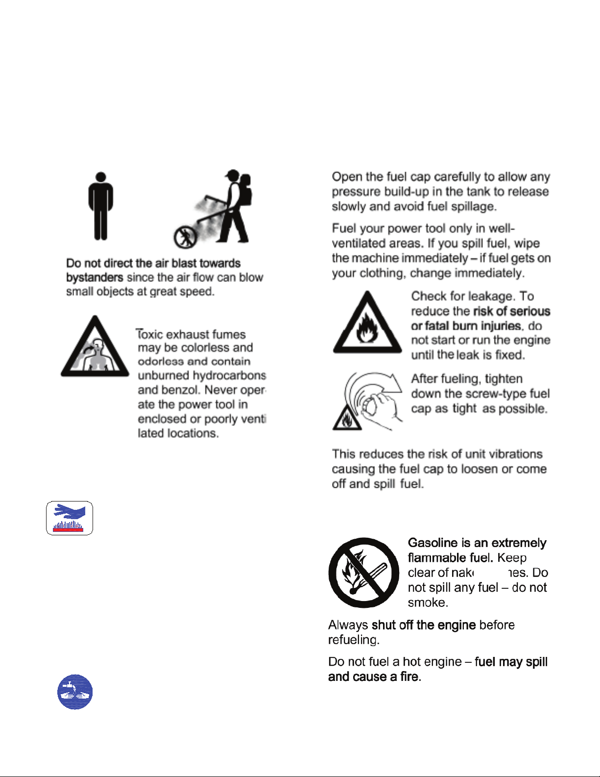
(2) Be sure no one stands in front of
nozzle, ev en though t h e handl e is set,
to stop, residual materials in pipe will blow out.
Spray Operation
Operation during cool weather with little
(1)
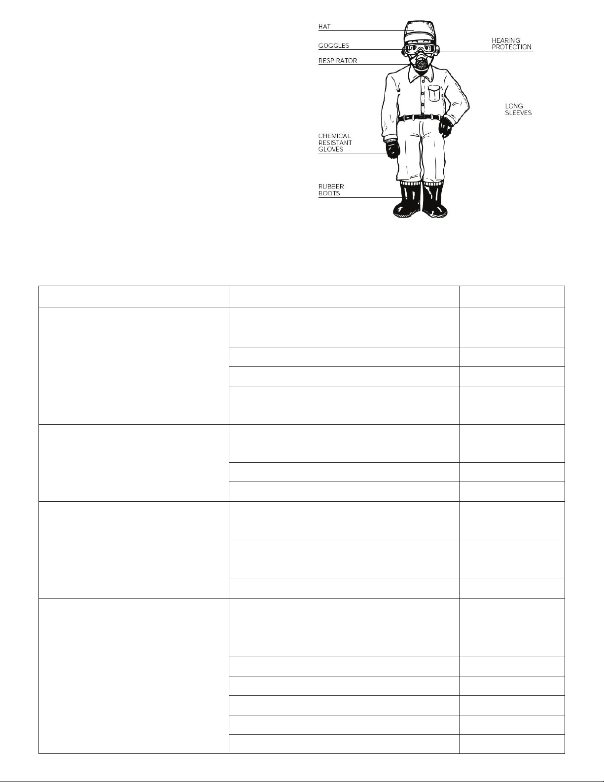
2.Proper Clothing
To reduce the risk of injury, the operator
should wear proper protective apparel.
•Carefully read this manual before
using this product.
•Wear ear mufflers to protect your
hearing.
wind is recommended. For example,
in the early morning or in the late afternoon.
This can reduce the evaporation and drift of
chemicals and improve spraying efficiency.
(2) Operator should face his/her back to wind.
(3) If your mouth or eyes are spattered
with chemicals, wash them with clean water
and go to see a doctor immediately.
(4) If the operator has a headache or
dizziness, stop working at once and go to
see a doctor immediately.
4
Page 6
(5) For the operator’s safety, dusting / spraying
must be carried out strictly according to the
Fueling
Keep the fuel tank far away from the
instruction of the chemicals and agricultural
requirements.
(6) If you want to stop the engine while
dusting, the throttle handle must be set to stop.
Warning
flames or sparks. Do not smoke
near fuel. When the machine is
running, do not add more fuel to
the fuel tank.
During operation, the muffler or
catalytic muffler and surrounding
cov er m ay b ecom e extremely
hot. Avoid contact durin g and
immediatel y a f t e r operation.
raelc aera tsuahxe peek syawlA
of flammable debris. Allow the
engine and muffler to completely
c o o l b efo r e p e rf o rmi n g a n y
maintenance activities.
After working, wash your hands
and clean all of clot hing. NOTE:
Residual pesticide can stain what
you touch.
while operating.
5
Page 7

Name
L×W×H (in) 18 × 13 × 25
Net Weight (lbs) 19.8
Chemical Tank Capacity (gal) 6.6
Water Absorption Volume (gal) 1.45
Working Pressure (MPa)
Mating Power 1E31F
Fuel Type
Way of ignition
Way of starting
Way of stopping
2. Main Application
This Tomahawk Power Backpack Sprayer is
the ideal portable tool for prevention of diseases
and for plant protection. It is mainly used in
prevention and cure of diseases and pests
of plants such as cotton, rice, wheat,
fruit trees, corn, greens, vines, etc.It can also
be used fo r residential and commercial pest
control, city sanitation, and greenhouses.
3. Main Features
3.1 This machine uses a gear structure to
decrease speed, so it is very durable.
3.2 The main part is the plunger pump
The structure is
allows for easy maintenance.
3.3 This machine has high pressure, great
flow and high efficiency, so the spraying of the
simple and compact, so it
0 ~ 2.5
Gasoline/Oil Mixture
CDI
Recoil starting
Shutting throttle fully
30:
1
4. Main Structur e
This machine consists mainly of:
4.1 Engine. It is the source of power
for the machine. It is connected to
the plunger pump through a decelerating device and connected to the
frame by a bottom support.
4.2 Plunger Pump. It is the heart of
the machine. It is connected to the
engine and to the frame.
4.3 Frame. It supports the machine.
4.4 Chemical Tank. It is used for
holding chemical liquid.
4.5 Spraying Parts. Consists of
plastic tube assembly, handle, valve,
straight spraying tube assembly and
long spraying nozzle.
4.6 Accessories. A single nozzle
conical gun and a heavy duty foundation
gun are available. Must purchase
separately.
chemicals is highly efficient.
6
Page 8

5.Operating Instructions
5.1 Preparation before start
5.1.1 Connecting spraying parts. Before starting, verify all the connections are working.
1
.Long Spraying Nozzle
2.Washer
3.Straight Spraying Tube
Never fill the fuel tank to the very top.
Never add fuel to the tank in a closed non-ventilated area.
Do not add fuel to this unit close to a open fire or sparks.
Be sure to wipe off spilled fuel before attempting to start the engine.
Do not attempt to refuel a hot engine.
.2 Start
5
5.2.1 Adding fuel. This gasoline engine is a single-cylinder, two stroke. The engine uses a fuel
mixture of No. 90 gasoline and two-strole oil. The gasoline oil mixture ratio is of 30:1 (gasoline : oil)
5.2.2 Push the fuel-injecting pump continuously until the pump is visibly is full.
5.1.2 Check that all the connections are correct and stable.
5.1.3 For long term storage, oil sealed must be removed first. To remove: Take off the spark plug,
use the lift thumb to stop the spark plug hole and pull the starter to remove oil.
5.1.4 Check the spark of the spark plug. Normally the sparks should be blue.
5
.1.5 Check if the air filter is clean. A dirty air filter will influence the volume of incoming air that
may cause bad engine performance.
4.Valve
5.Handle
6.Plastic Tube
Figure 2
5.2.3 Move the fuel handle in the starting position (about one third of the whole scale).
See Figure 3.
5.2.4 Pull the starter lightly 3-5 times to push fuel into the cylinder. Then pull faster to start the
engine.
Note: After starting the engine, the recoil starter
should be retracted slowly. If the rope on the recoil
retracts fast, it may cause damage to the engine.
5.2.5 Next, move the choke slowly to full open position. Regulate the fuel handle to a proper position to
run at a low speed for 3-5 minutes.
5.2.6 New machines should not work at full open
position within the first 4 hours. The speed should
be controlled at 4000-5000 rpm.
Figure 3
5.3 Spraying
5.3.1 When adding chemical liquid, it should be poured slowly into the chemical tank. The liquid
must be poured through the filter in order to avoid undesired matter from entering into the liquid
tank, which could cause harm to the chemical tank or engine. After adding liquid, screw down the
chemical tank lid in order to avoid leakage.
5.3.2 Regulate the choke (see Figure 4) to the closed position to start and then move to the full
open position when the engine is hot.
7
Page 9

5.3.3 Important notes when spraying:
A) Swing the spraying tube with your hand after
turning on the handle valve. In order to avoid
chemical harm, it is strictly prohibited to spray
only in one place.
B) Operator should face the wind. The spraying
tube should form an approximate 15° angle.
C) During spraying, the spraying tube should be
swung continuously between the left and the right
to increase spraying range.
5.3.4 Pressure regulation. When the engine’s speed
is 5000-6000rpm, regulate the water pressure of
the plunger pump.
If it is necessary to regulate, please do this
procedure as per the instructions on Figure 5.
Figure 4
5.3.4 Spraying. Regulate the fuel handle to allow the
machine to run at about 6500r/min and turn on the
handle spraying valve to begin spraying.
5.3.5 Stopping. Move the stop switch to the STOP
position when the engine idles.
Figure 5
5.4 Avoid fire.
a) NEVER start a fire or smoke near the machine.
b) NEVER refuel the machine when it is hot or running.
c) NEVER pour fuel on the machine. If you do, clean it
immediately. After adding fuel, screw down the fuel tank
lid, then move the machine to a new place to start the engine.
Figure 6
5.5 Spraying operation.
a) Chemical spraying should be performed under cool weather with little wind. We recommend
spraying early in the morning or in the late afternoon. This will reduce evaporation and drift of
chemicals improving spray efficiency.
b) The operator must walk facing the wind.
c) If chemical touches the operator’s mouth or eyes, wash them immediately with clean water and
and then visit a doctor.
d) If the operator has a headache or feeling dizzy, he must stop working immediately and should
visit a doctor.
e) For the operator’s safety, spraying must be carried out strictly according to the instruction
of the chemicals being used.
8
Page 10
6.Safe Operation
6.1 Read the instruction manual carefully.
6.2 Protective gear:
a ) Wear a flanged cap
b ) Wear dirt/fog-proof goggles
) Wear a gauze mask
c
) Wear a coat guard
d
e ) Wear long sleeve gloves
f ) Wear boots
7.Troubles hooting
7.1 Engine troubleshooting guide
Problem Cause Remedy
Fails to start Fail to push the fuel-injecting pump Push continuously
Water mixed with fuel Replace the fuel
Deterioration or carbon deposit of spark plug Replace the plug
Bad contact between spark plug and lead
wire
It starts but cannot run at high speed The choke is not on the full open position Open to full
Wrong ratio of fuel Replace
Water in fuel Replace the fuel
It runs but does not work efficiently The air filter is dirty Check and clean
Outlet of cylinder and muffler are dirty Remove the dirt
Piston, piston ring, cylinder have been worn Replace
Stops while running Fuel is out Add fuel
Check spark plug
position
The lead wire of plug is loose Check and replace
Plug covered with carbon Replace the plug
The filter is clogged Clean
Water in fuel Replace fuel
The air hole in the tank lid is clogged Clean
9
Page 11

7.2 Troubleshooting for spraying
Problem Cause Remedy
Liquid does not spray out Inlet valve and outlet valve blocked Replace or clean
Washer is damaged Replace
6004Z bearing is damaged Replace
Piston is damaged Replace
Low or no spraying pressure
Pressure is fine but spraying is low Piston is worn Replace
Not enough pressure
Not enough elastic force on regulating spring Replace
Corrosion resistant steel ball worn Replace
Pressure regulating valve seat worn Replace
Piston running distance is not enough Replace
Regulate
Inlet valve and outlet valve are worn Replace
Spraying parts are clogged Clean
Spraying mist is low The holes of spraying sheet are worn Replace
Spraying parts are clogged Clean
Warranty and Service
Tomahawk Power guarantees problem-free quality and will assume the costs for defect remediation by
replacing defective parts in the case of material or manufacturing defects that occur within the guarantee
period a the date of purchase. Please note that specific guarantee conditions apply in some countries. Ask your
sales person if you have any questions. As vendor of the products he is responsible for the guarantee. We
request your understanding that no guarantee can be assumed for damages due to the following: • Noncompliance with the operating instructions. • Neglecting required maintenance and repair work. • Damages
due to improper carburetor adjustment. • Normal wear and tear. • Obvious overload through persistently
exceeding the upper performance limits. • Using non-approved tools and cutting fixtures, Using non-approved
cutting bar and chain lengths in the case of chain saws. • The use of force, improper handling, misuse, or
accident. • Damages caused by overheating due to dirt build up on the ventilator casing. All guarantee work
must be carried out by a Tomahawk Power dealer.
Parts subject to wear and tear must be replaced, when required.
The following parts are subject to normal wear and are not covered by the manufacturer’s warranty:
• Air filter • Fuel filter • All rubber parts which come into contact with fuel •
Spark Plug • Starter
10
Page 12
9. Te ch n ic al M ai n te na nc e a nd
Long Term Storage
(1)Spraying units
a.Clean out any residual chemical mixture
in the chemical tank and all other
operation with clean water and and dry.
b.Clean the chemical tank inside and out
after spraying.
c.Loosen the chemical tank lid.
d.Let the machine run at a low speed 2-3
minutes after cleaning.
(2)Fuel system maintenance
a.Water or dirt in fuel is one of the main
cause of the engine trouble, clean the fuel
system regularly.
b.Residual fuel remaining in the fuel tank
and carburetor for an extended period will
clog the fuel system, causing the engine not
to work properly Fuel should be discharged.
if the machi
ne will not be in sure for a week.
parts after
Note:
The wor k including main t e nance,
cleaning and adjusting must be done
after stopping the machine.
Periodically ch eck the braces.
Without del ay, replace the worn out
braces.
(4)Long term storage
a.Clean the machine and apply antirust oil to
metal parts.
b.Remove the spark plug and pour 15~20g
of 2-stroke engine oil into the cylinde r
through the spark plug pole. Pull the starter
handle 4~5 times to distribute
the engine. Pull the handl
piston reaches the top of
it there, then install the spark plug.
the oil inside
e slowly until the
its travel and leave
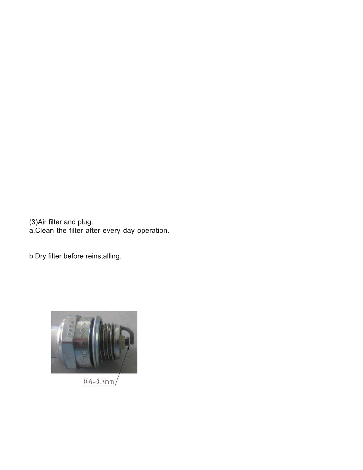
Dirt adhering to the filter reduces the engine
power.
c.Clean stains or carbon off the spark plug
and adjust spark gap to 0.6~0.7mm.
d.The plug model of this machine is 4106J,
as seen on Figure 13.
Do
not use other models.
c.Remove the chemical
inside and outside, then leave the lid loose.
d.Remove spray wands and clean them. Store
separately.
e.Discharge fuel in the
entirely.
f.Cover the machine w
and store it in a dry and clean place.
tank lid, and clean
tank and carburetor
ith a plastic dustcoa
t
Fig 13
11
Page 13
Page 14

Page 15

Page 16

Page 17

Page 18

 Loading...