

Page 1
ENGDEUESP
MANUFACTURED BY:
Indoorcycling Group GmbH
Happurger Str. 86
90482 Nuremberg | Germany
info@indoorcycling.com
www.indoorcycling.com
Phone: +49(0)911 / 54 44 50
ENGDEUESP
CAUTION!
READ ALL PRECAUTIONS AND INSTRUCTIONS IN THIS MANUAL BEFORE YOU START
USING THIS EQUIPMENT. PLEASE KEEP THIS MANUAL FOR FUTURE REFERENCE.
IMPROPER ASSEMBLY, USE OR MAINTENANCE CAN VOID THE WARRANTY TERMS.
IC2
MODEL NO:IC-TKIC2B-01
Version 1.1 2014 IC-TKIC2B-01 Copyright by Indoorcycling Group GmbH 2014 | www.indoorcycling.com
Page 2

Version 1.1 2014 IC-TKIC2B-01 Copyright by Indoorcycling Group GmbH 2014 | www.indoorcycling.com
TECHNICAL SPECIFICATIONS:
The TOMAHAWK IC2 Bike is according to EN 957 a Class S product for professional
and / or commercial use. Such training equipment is intended for the use in training areas
of organizations such as tness clubs or sport associations, where access and control is
specially regulated by the person who has the legal responsibility.
WARNING!
The bike is designed to accommodate most users from
150 cm to 205 cm (4’11’’ to 6’ 9’) body height.
TABLE OF CONTENTS
IMPORTANT PRECAUTIONS P.3
GETTING STARTED P.4
HOW TO ASSEMBLE THE INDOOR CYCLE P.5-7
INITIAL INSTALLATION CHECKS P.8-9
HOW TO ADJUST THE INDOOR CYCLE P.10-12
RESISTANCE ADJUSTMENT P.13
HOW TO MOVE THE INDOOR CYCLE P.13
PREVENTIVE MAINTENANCE P.14-18
MAINTENANCE ACTIVITY PLAN P.19
SPARE PARTS P.20-25
LIMITED WARRANTY P.26-27
FOOT PRINT: 53 X 115 CM / 20.9 X 45.3 INCH
WEIGHT OF BIKE: 48 KG / 106 LBS
MAX SADDLE HEIGHT: 116 CM / 45,7 INCH
MAX HANDLEBAR HEIGHT: 119 CM / 47 INCH
MAX USER WEIGHT: 130 KG / 287 LBS
Page 3

3
ENG
1. It is the sole responsibility of the owner to
ensure that all users of the indoor cycle are
informed and aware of all warnings
and precautions.
2. Operate and maintain the indoor cycle
only as described in this manual and after
proper assembly and functionality check as
described in this manual.
3. Keep the indoor cycle indoors, away from
moisture and dust. Do not place the indoor
cycle in a garage or covered patio or near
water or pools.
4. Place the indoor cycle on a level surface.
To protect the oor or carpet from damage,
place a mat beneath the indoor cycle.
Make sure that there is adequate room (20
inches/0,5m) around the indoor cycle to
assemble, disassemble and operate it.
5. Regularly inspect and properly tighten all
parts of the indoor cycle as recommended in
this manual. Please replace defective parts
immediately and do not use the Bike until
repair is performed. Only use original parts
from the manufacturer.
6. Children under the age of 14 should
only be allowed use of the indoor cycle
with parental approval and supervision. If
the indoor cycle is not in use, please make
sure the brake resistance is fully engaged
to prevent drive gear components from
movement and to avoid the potential risk of
injury due to improper use.
7. The indoor cycle should not be used by
persons exceeding weight of 287 lbs/130 kg.
8. Always wear appropriate riding gear and
shoes for cycling while operating the indoor
cycle. Do not wear loose clothes or shoes
with loose laces which could become caught
on the indoor cycle.
9. Before using the indoor cycle, make sure
you are familiar with the setup/operation of
the indoor cycle.
10. The indoor cycle does have a direct
driven ywheel (wheel); the pedals will
continue to move along with the ywheel
until the ywheel stops.
11. Always regulate the ywheel resistance
so that your pedalling motion is controlled.
12. Keep your back straight while using the
indoor cycle; do not arch your back.
13. If you feel pain or dizziness while
exercising, stop immediately, rest and cool
down and consult a physician.
14. If replacement parts are needed, use only
manufacturer supplied parts.
IMPORTANT
PRECAUTIONS
WARNING!
To reduce the risk of serious injury, read the following
precautions and information carefully before
operating the indoor cycle.
WARNING!
Before beginning any exercise program, consult
your physician. This is especially important for
persons over the age of 35 or persons with pre-
existing health problems. Read all instructions
before using. Be aware that incorrect or extensive
training may result in serious health injuries.
The manufacturer assumes no responsibility for personal injury or
property damage related by or through the use of this product.
Page 4
Version 1.1 2014 IC-TKIC2B-01 Copyright by Indoorcycling Group GmbH 2014 | www.indoorcycling.com
GETTING STARTED
DEAR CUSTOMER,
Congratulations for selecting the TOMAHAWK IC2. The TOMAHAWK indoor cycle oers an
impressive array of features designed to enhance cardiovascular tness, tone muscles, and
develop endurance. Whether users are beginners or experienced athletes, the TOMAHAWK IC2
oers workouts that will help users to reach their individual tness goals.
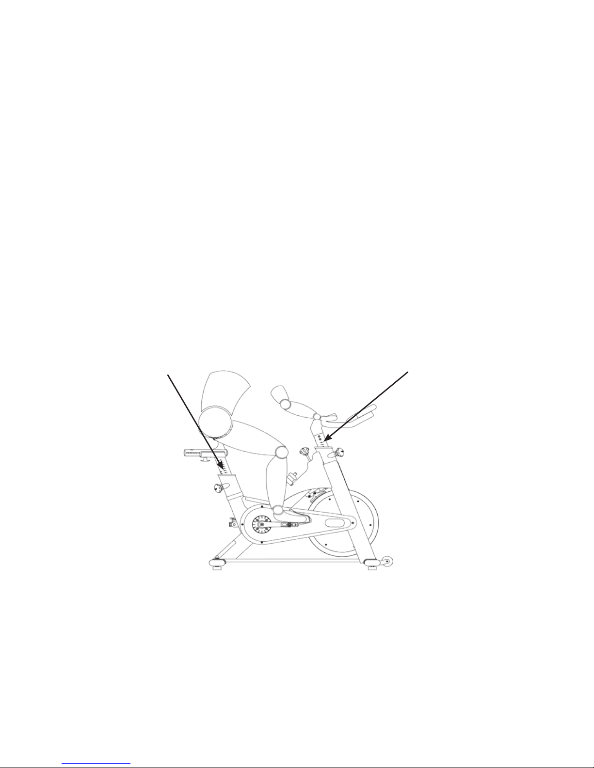
IMPORTANT: Read this manual carefully before assembling or using the indoor cycle. If you have
questions after reading this manual, please contact your local distributor or refer to the website
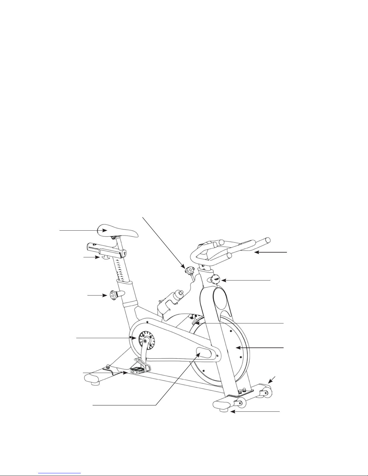
www.indoorcycling.com. Before reading further, please familiarize yourself with the parts that
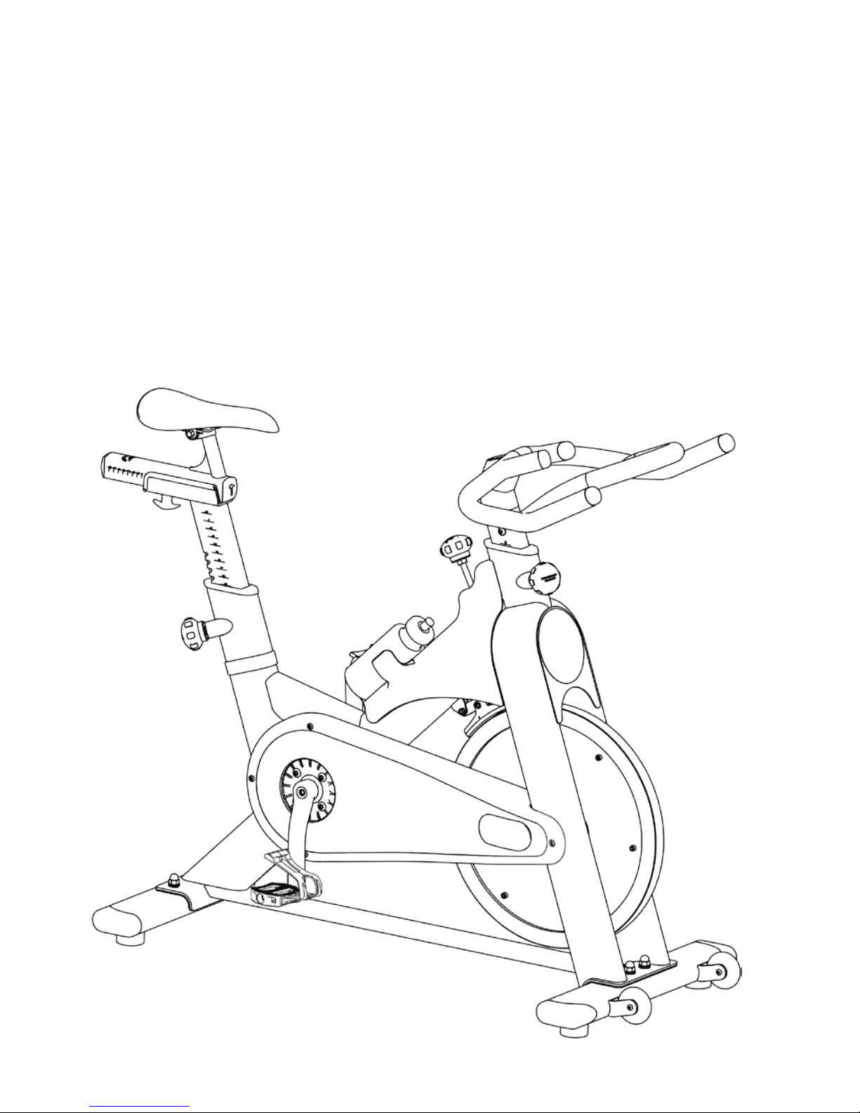
are labeled in the drawing below.
YOU WILL FIND THE PRODUCTION CODE ON THE LEFT SIDE OF THE TOMAHAWK IC2 WITHIN THE LOWER
RANGE OF THE FRAME. PLEASE REGISTER THESE IN SERVICING AND MAINTENANCE LISTS.
EMERGENCY BRAKE & RESISTANCE KNOB
SADDLE
T- LOCK HANDLE
ADJUSTMENT KNOB
PEDAL /TOE CLIP
CHAIN GUARD
MAINTENANCE COVER
HANDLEBAR
ADJUSTMENT KNOB
BRAKE PAD
FLYWHEEL
TRANSPORT WHEEL
LEVELLING FEET
Page 5
5
ENG
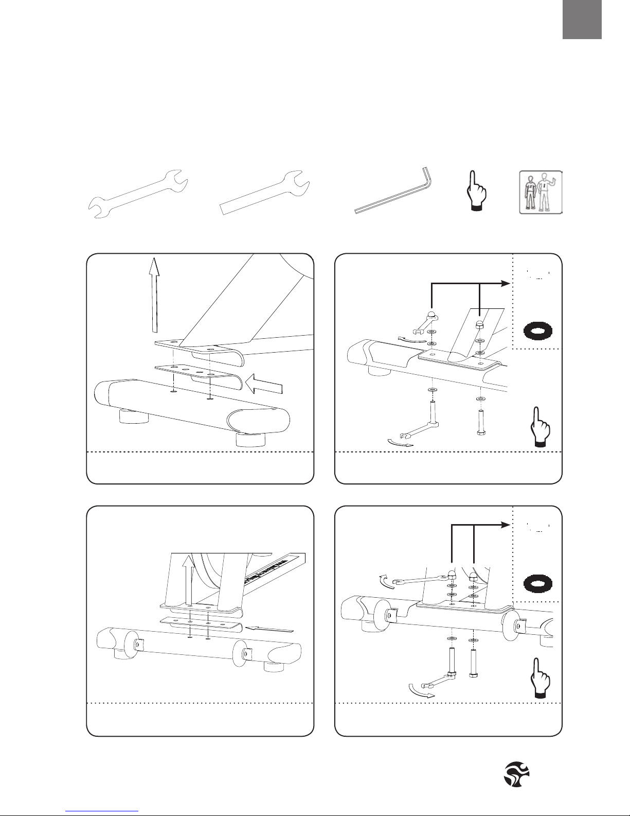
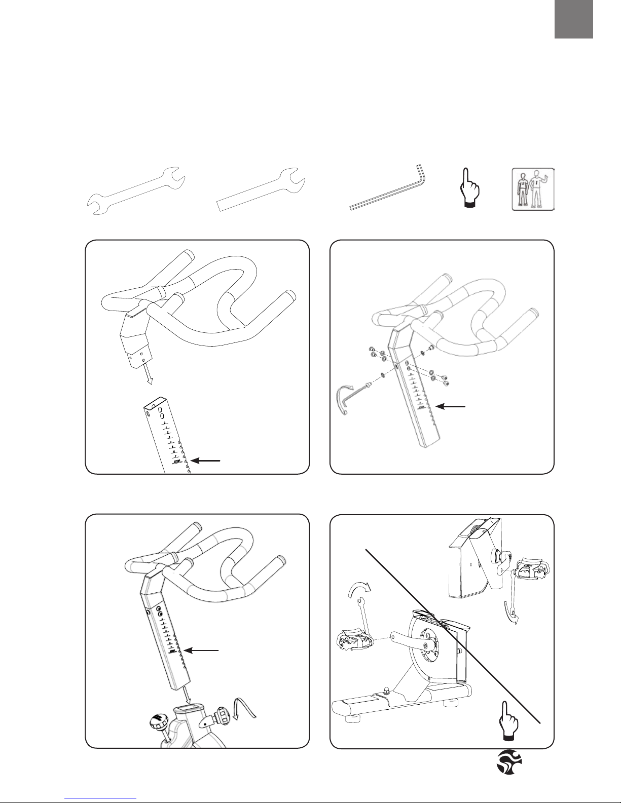
HOW TO ASSEMBLE THE
INDOOR CYCLE
SW 17/19MM
SW 13/15MM
15MM
WRENCH
2X 1X
3MM
6MM
HAND
TIGHT
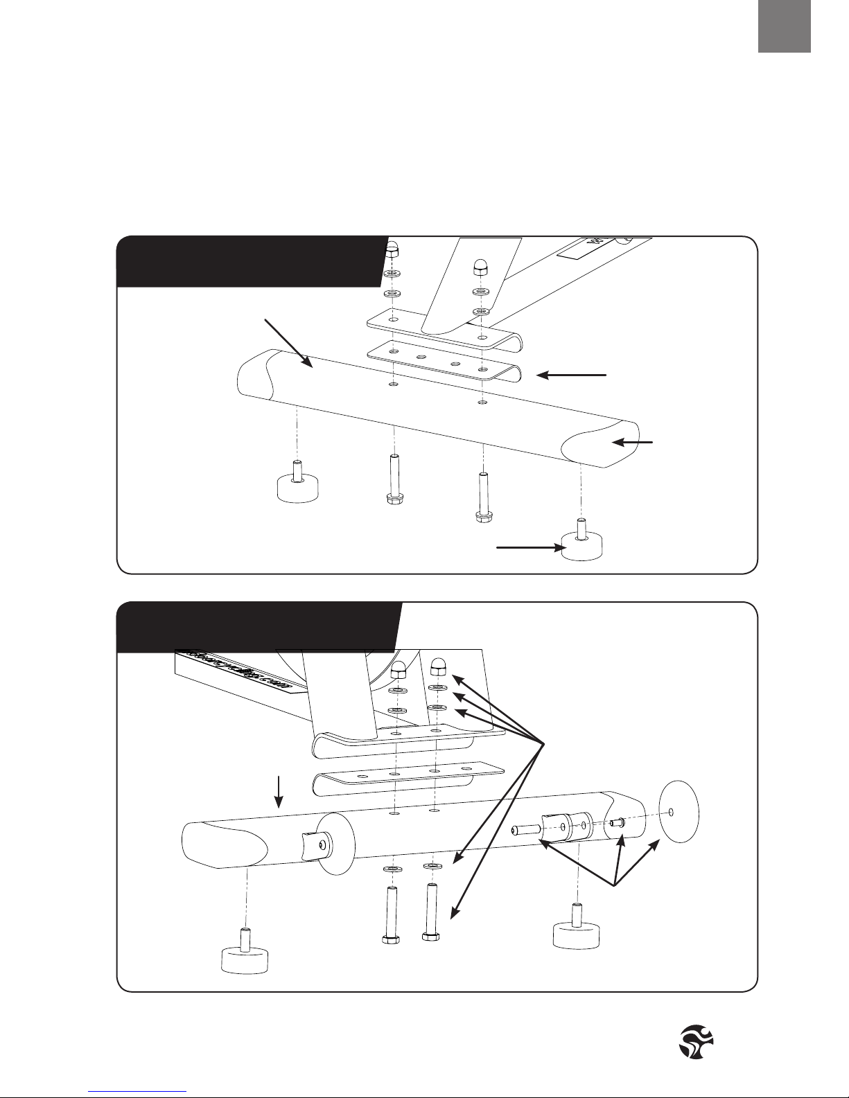
1. 2.
4.3.
ASSURE THAT PLASTIC GASKET IS PLACED BETWEEN
STABILIZER AND FRAME.
ASSURE THAT PLASTIC GASKET IS PLACED BETWEEN
STABILIZER AND FRAME.
ASSURE THAT BLACK RUBBER WASHER IS PLACED
BETWEEN UPPER FRAME AND BOLT/WASHER.
ASSURE THAT BLACK RUBBER WASHER IS PLACED
BETWEEN UPPER FRAME AND BOLT/WASHER.
Page 6
Version 1.1 2014 IC-TKIC2B-01 Copyright by Indoorcycling Group GmbH 2014 | www.indoorcycling.com
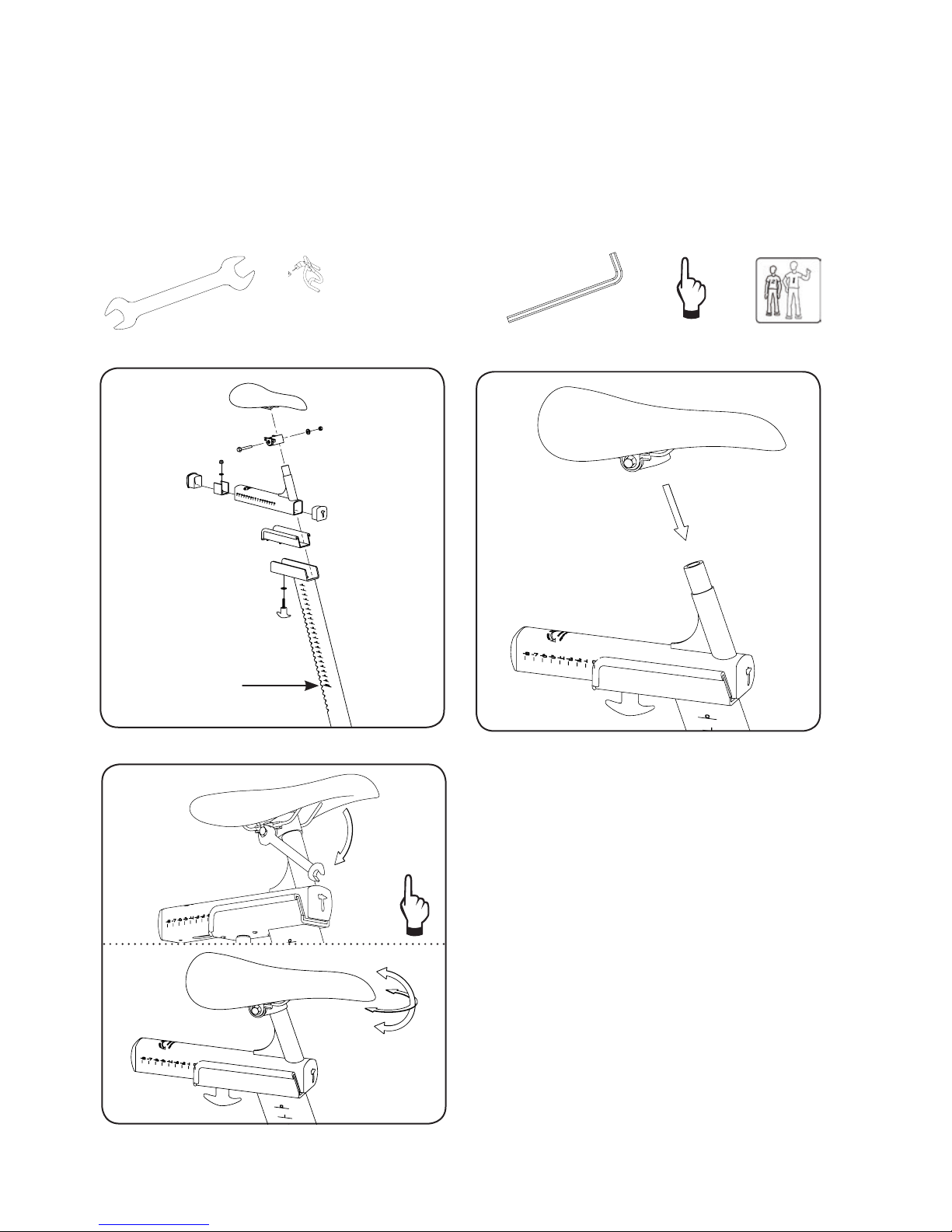
HOW TO ASSEMBLE THE
INDOOR CYCLE
WARNING!
Make sure the seat is xed properly in
a LEVEL HORIZONTAL position and
securely tigthend from both sides!
5. 6.
STOP MARK
SW 17/19MM
SW 13/15MM
15MM
WRENCH
3MM
6MM
HAND
TIGHT
7.
Page 7
7
ENG
HOW TO ASSEMBLE THE
INDOOR CYCLE
8. 9.
STOP MARK
STOP MARK
STOP MARK
SW 17/19MM
SW 13/15MM
15MM
WRENCH
2X 1X
3MM
6MM
HAND
TIGHT
11.
10.
WARNING!
Pedal marked R installed on right crank (clockwise). Pedal marked L installed on left crank (counter-clockwise)
Pedals must be fastened with signicant strength to avoid loosening with use of the TOMAHAWK IC2.
Page 8

Version 1.1 2014 IC-TKIC2B-01 Copyright by Indoorcycling Group GmbH 2014 | www.indoorcycling.com
INITIAL
INSTALLATION CHECKS
The cycle tune-up must be performed at initial installation of the TOMAHAWK IC2
for optimal performance and longevity. Please read and follow all instructions
below. If the TOMAHAWK IC2 is not installed and tuned as described, components
may wear excessively and the TOMAHAWK IC2 may become damaged. If you have
questions about the installation, please contact service@indoorcycling.com.
Note: Some maintenance procedures require acid-, silicone- and solvent free spray
lubricant (for example BRUNOX), and white lithium grease.
1. Make sure that the TOMAHAWK IC2 is leveled. If the TOMAHAWK IC2 rocks on the oor, turn
the leveling feet underneath the front and/or rear stabilizer until the rocking motion is elimina
ted.
2. Verify emergency brake function to assure that emergency brake functions correctly.
3. Brake pad calibration: Turn resistance knob counterclockwise as far as possible (minimum
braking eect), verify that there is a slight separation of the brake pad from ywheel. Brake pad
should barely touch the ywheel when resistance knob is turned counter-clockwise as far as it
can go.
4. Apply spray lubricant to the brake pad using the lubrication holes on the plastic part or the
brake pad and externally on the felt pad. Make sure brake pad is thoroughly soaked from end
to end with lubricant spray. Then, wipe the excess o from the ywheel.
* Best Practice: Use a rellable spray bottle lled with non-aerosol acid-, silicone- and
solvent free spray lubricant purchased by the gallon (3.7 L) at the local hardware store.
5. Apply lithium grease to the threads on the lower end of the brake rod. First, turn the resistance
knob clockwise until it stops. Apply a small amount of white lithium grease to the threads on
the brake rod above the two lock nuts. Then, turn the resistance knob counter-clockwise
until it stops.
Page 9

9
ENG
INITIAL
INSTALLATION CHECKS
6. Apply lithium grease on the metal threads of all the adjustment knobs.
7. Verify four (4) allen nuts on RS pulley for tightness. If loose, apply LocTite Threadlocker
Blue-243 and retighten.
8. Verify R and L crank arm allen bolts for tightness. If loose, apply LocTite Threadlocker
Blue-243 and retighten.
9. Verify belt tension. Check if belt drive is rmly tightened and does not slip while riding under
resistance load. In case that the belt slips, proceed using the adjustment technique as described
on page (18). Please note that a belt drive gear never shows slack. In case of adjustment do not
apply too much tension.
10. Wipe down bike frame with rag moistened with solvent free spray lubricant
11. Some parts of the TOMAHAWK IC2 may become loose during shipment. Check crank arms,
check all exposed screws, bolts, and nuts, and make sure that they are properly tightened.
CUSTOMER SERVICE
1. Provide basic maintenance instructions to client and direct them to detailed maintenance
instructions (page 14-19 )
2. Sign-o sheet provided to client to conrm explanation of maintenance procedures/manual
and verication of condition of bikes?
Page 10
Version 1.1 2014 IC-TKIC2B-01 Copyright by Indoorcycling Group GmbH 2014 | www.indoorcycling.com
HOW TO ADJUST THE
INDOOR CYCLE
The TOMAHAWK IC2 can be adjusted for maximum comfort and exercise eectiveness. The
instructions below describe one approach to adjusting the TOMAHAWK IC2 to ensure optimal
user comfort and ideal body positioning; you may choose to adjust the TOMAHAWK IC2 cycle
dierently.
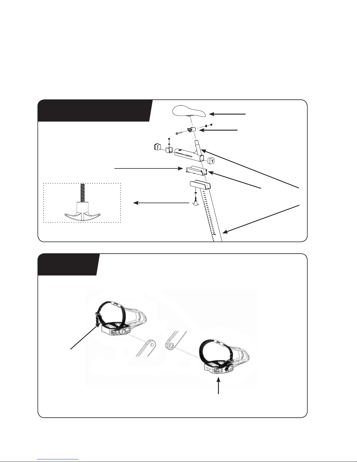
PEDAL STRAP ADJUSTMENT:
Sit on the saddle and position your feet on the pedals, with the balls of your feet directly above
the spindles of the pedals (see the drawing below). Adjust the pedal straps so the toe clips
(cages) are snug but not too tight. Note: In the case of a bike being tted with combi-pedals, the
pedals feature toe clips on one surface and SPD cleats on the opposite surface. If desired, use the
shoe cleats with cycling shoes instead of the toe clips.
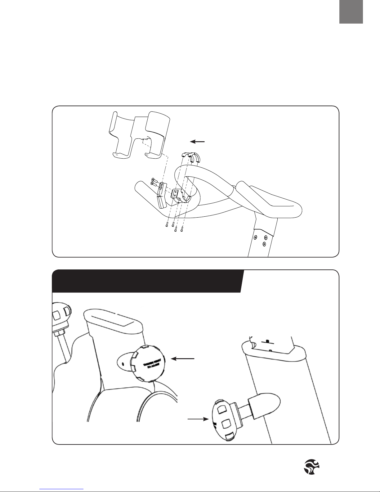
Please do not adjust
handlebar height beyond
the STOP mark on the
stem and ensure the pop
pin is fully engaged
and securely tightened
WARNING!
Please avoid overtightening the pop pin adjustment knob as this may cause damages to the
vertical aluminum stems.
SADDLE HEIGHT ADJUSTMENT:
Sit on the saddle and slowly pedal until the right pedal is in the lowest position. Your knees
should be slightly bent without a dropping of the hips. To avoid hyper extending your knees,
make sure that your legs are not completely straight.
Please do not adjust
saddle height beyond
the STOP mark on the
stem and ensure the pop
pin is fully engaged and
securely tightened
Page 11
11
ENG
HOW TO ADJUST THE
INDOOR CYCLE
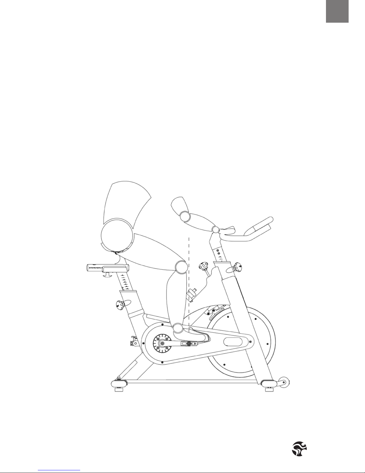
SADDLE HORIZONTAL ADJUSTMENT:
Proper horizontal adjustment of the saddle is very important in avoiding injury to the knees.
Sit on the saddle and move the pedals until the crank arms are in horizontal position.
Using your forward most leg as a marker, your kneecap should be directly above the center of the pedal so that a straight
line is created between knee and center of the pedal (see the dotted line in image below). To adjust the horizontal position of the saddle, rst dismount the TOMAHAWK IC2. Next, loosen the rear adjustment knob, slide the saddle forward or
backward as required, and then retighten the knob.
Page 12
Version 1.1 2014 IC-TKIC2B-01 Copyright by Indoorcycling Group GmbH 2014 | www.indoorcycling.com
HOW TO ADJUST THE
INDOOR CYCLE
If your TOMAHAWK IC2 is equipped with a regular 2 way handlebar. If the handlebar is too close
to the saddle, your breathing may feel restricted; if the handlebar is too far from the saddle,
you may experience back discomfort. To adjust the horizontal position to the handlebar, rst
dismount the TOMAHAWK IC2.
Check for proper handlebar position by positioning your elbow so that it is touching the front tip of the saddle at a
90 degree angle and checking that the ngertip of your middle nger is touching the handlebar at the mid-point. If it
is not as described then loosen the fore-aft T-lock handle and slide the saddle slightly forward or backward until your
middle nger is touching the handlebar at the mid-point, and then retighten the handle. Changing your hand position
can change the angle of your back, neck, and arms. To minimize the stress on your muscles during your workouts, change
your hand position frequently.
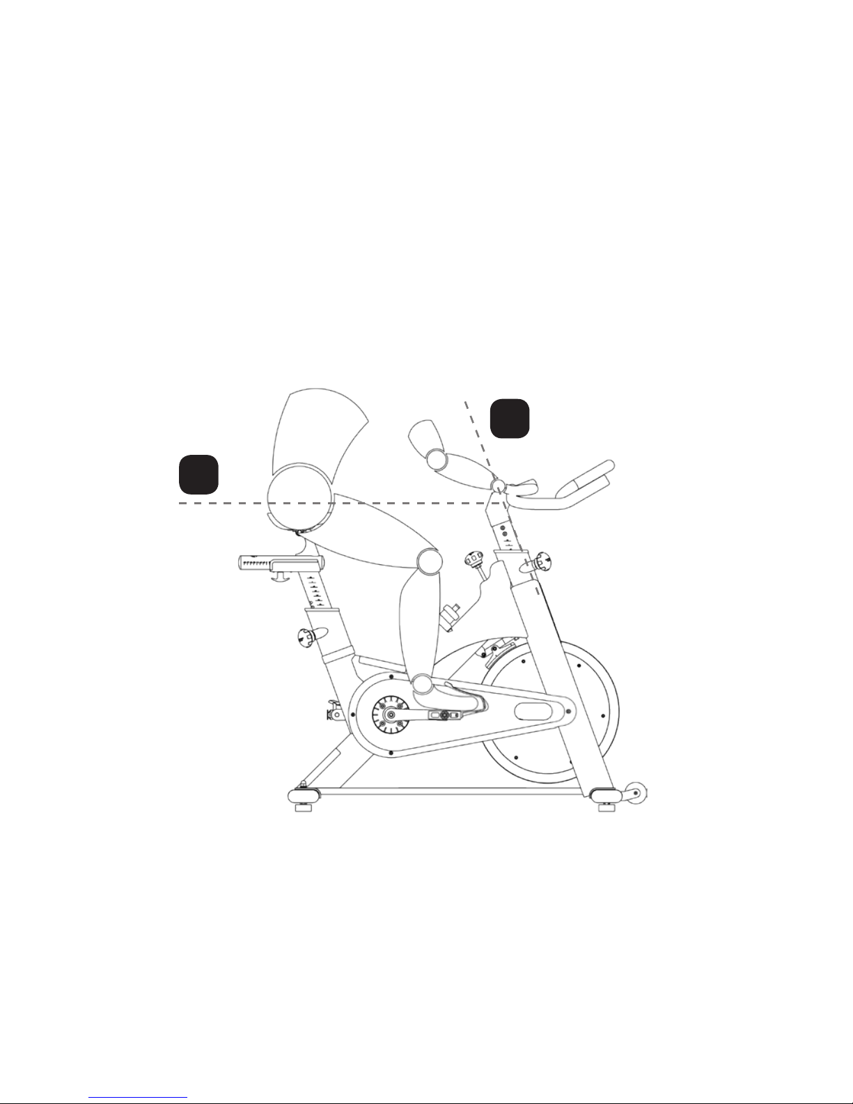
HANDLEBAR ADJUSTMENT:
Begin with the top of the handlebar at relatively the same height or just slightly higher than
the top of the saddle (dotted horizontal line A in the drawing above) and at a neutral fore/
aft position (see dotted vertical line B in drawing above). If your knees touch the handlebars
or if you experience back discomfort while pedalling for extended periods of time, the height
of the handlebars can be adjusted. First, dismount the TOMAHAWK IC2. Next, turn the front
adjustment knob counter clockwise, slide the handlebar post up or down, and then re-tighten
the adjustment knob.
A.
B.
Page 13
13
ENG
HOW TO OPERATE THE
INDOOR CYCLE
RESISTANCE ADJUSTMENT:
The preferred level of diculty in pedalling (resistance) can be regulated in ne increments by
use of the resistance knob. To increase the resistance, turn the resistance knob clockwise. To
decrease the resistance, turn the knob counter clockwise.
IMPORTANT: To stop the ywheel (wheel) while pedalling, push down on the red brake knob. The ywheel should
quickly come to a complete stop. Please make sure your shoes are xed into the toe clip or in case cycling shoes are
used your shoe cleat is connected to the pedal binding while riding.
HOW TO MOVE THE TOMAHAWK IC2:
Due to the weight of the TOMAHAWK IC2, it is recommended that two persons move it. While
one person lifts the back of the TOMAHAWK IC2, the second person rmly holds the handlebar
and tips the TOMAHAWK IC2 forward until it rolls on the wheels. Carefully move the indoor
cycle to the desired location and then lower it. CAUTION: To reduce the risk of injury,
use extreme caution while moving the indoor cycle. Do not attempt to move it over
uneven surfaces and make sure a safety space of min 20 inch to the nearest
equipment is redeemed.
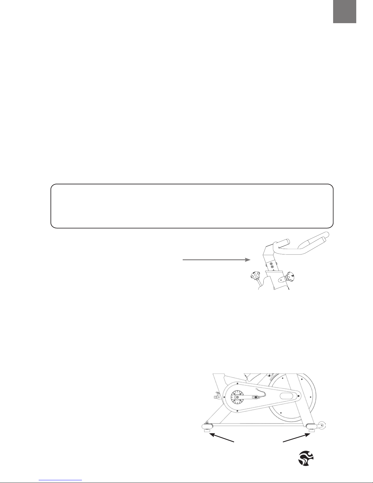
If the TOMAHAWK IC2 rocks on the oor after being set
down, turn the levelling feet (see diagram) underneath
the front or rear stabilizer until the rocking motion is
eliminated.
Important: Please do not unscrew the levelling feet
more then ½ inch!
LEVELLING FEET
The TOMAHAWK IC2 does not have a free moving flywheel (wheel); the pedals will continue to move together with the
flywheel until the flywheel stops. Reducing speed in a controlled manner is required. To stop the flywheel immediately,
push down the red break knob. Always pedal in a controlled manner and adjust your
desired cadence according to your own abilities.
PUSH THE RED KNOB DOWN = EMERGENCY STOP
RED RESISTANCE KNOB (TURN)
EMERGENCY BRAKE (PUSH)
Page 14

Version 1.1 2014 IC-TKIC2B-01 Copyright by Indoorcycling Group GmbH 2014 | www.indoorcycling.com
PREVENTIVE
MAINTENANCE
WARNING!
REGULAR MAINTENANCE MUST BE PERFORMED ON THE TOMAHAWK IC2 FOR OPTIMAL
PERFORMANCE AND LONGEVITY.
Please read and follow all instructions below. If the TOMAHAWK IC2 is not maintained as
described, components may wear excessively and the TOMAHAWK IC2 may become damaged.
Improper maintenance will void the warranty terms. If you have questions about maintenance,
contact your local distributor or refer to www.indoorcycling.com
NOTE: MANY MAINTENANCE PROCEDURES REQUIRE LUBRICANT SPRAY.
MANUFACTURER RECOMMENDS FOR EXAMPLE BRUNOX OR A SIMILAR
SOLVENT- AND ACID FREE LUBRICANT.
DAILY MAINTENANCE:
1. Make sure that the TOMAHAWK IC2 is leveled. If the TOMAHAWK IC2 rocks on your oor, turn
the levelling feet underneath the front or rear stabilizer until the rocking motion is eliminated
(see HOW TO MOVE THE TOMAHAWK IC2 on page 13).
2. After each user nishes exercising, the TOMAHAWK IC2 should be disinfected and cleaned
to maintain a hygienic environment. First, apply a disinfectant spray to the handlebars and the
saddle. Using a lint-free cloth, dry the handlebars and the saddle. Next, apply a small amount
of disinfectant to a lint-free cloth and clean the adjustment knobs and the
adjustment handles. Avoid using strong detergents on the TOMAHAWK IC2 frame.
WEEKLY MAINTENANCE:
1. Apply a small amount of the lubrication spray to a lint-free cloth, and thoroughly clean the
frame, the handlebar slider and seat sliders the ywheel and the plastic parts of the
TOMAHAWK IC2.
2. For optimal performance of the resistance
system, and to minimize wear on the brake
pad, the acid-, silicone- and solvent free spray
lubricant should be applied to the brake pad
using the lubrication holes on the plastic
part of the brake pad. If fuzz or lint appears
on the brake pad, the brake pad has become
too dry-lubricant spray should be applied
more frequently. Make sure brake pad is
thoroughly soaked from end to end with
lubricant spray. Then, wipe the excess o.
Page 15
15
ENG
PREVENTIVE
MAINTENANCE
BI-WEEKLY MAINTENANCE:
1. The TOMAHAWK IC2 should not be used if
the emergency brake system is not working
properly. While sitting on the saddle and
pedalling, test the brake by pushing down
the brake knob. The ywheel should come to
a quick and complete stop.
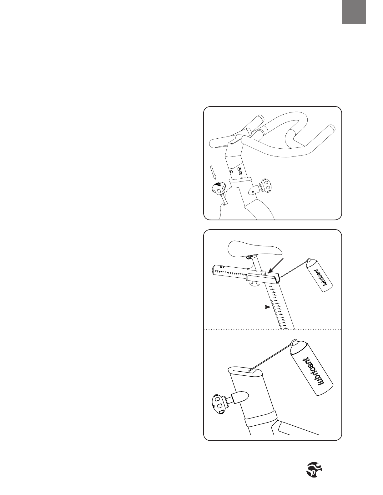
2. To maintain the easy adjustability of
the saddle post, the saddle post should
be cleaned and lubricated. Turn the rear
adjustment knob counter clockwise and slide
the saddle post out of the frame. Apply a
small amount of lubricant spray to a lint-free
cloth, and clean the saddle post (A). Next,
apply a small amount of lubricant spray
inside of the rear frame sleeve. Then, reinsert
the saddle post into the frame and adjust it to
the desired height.
Next, loosen the rear lock handle and slide the saddle
carriage as far backward as possible. Apply a small amount
of lubricant spray to a lint-free cloth, and clean the top of
the saddle slide (B). Then, slide the saddle carriage as far
forward as possible and clean the top of the saddle slide.
Finally, adjust the saddle to the desired position.
A
B
1.
2.
Page 16
Version 1.1 2014 IC-TKIC2B-01 Copyright by Indoorcycling Group GmbH 2014 | www.indoorcycling.com
PREVENTIVE
MAINTENANCE
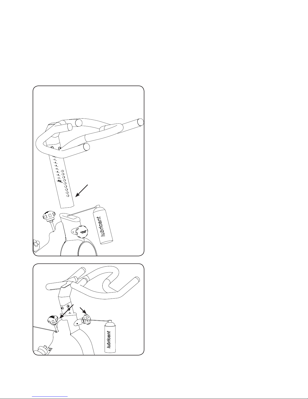
3. To maintain the easy adjustability of the
handlebar post, the handlebar post should
be cleaned and lubricated. First, turn the
front adjustment knob counter clockwise and
slide the handlebar post out of the frame.
Apply a small amount of lubricant spray to a
lint-free cloth, and clean the handlebar post
(A). Next, apply a small amount of lubricant
spray inside of the front frame sleeve.
Then, reinsert the handlebar post into the frame
and adjust it to the desired height.
MONTHLY MAINTENANCE:
1. To maintain the smooth function of the
adjustment knobs controlling the handlebar
and saddle, the metal threads on the
adjustment knobs (A) must be lubricated.
1.
A
A
3.
Page 17
17
ENG
PREVENTIVE
MAINTENANCE
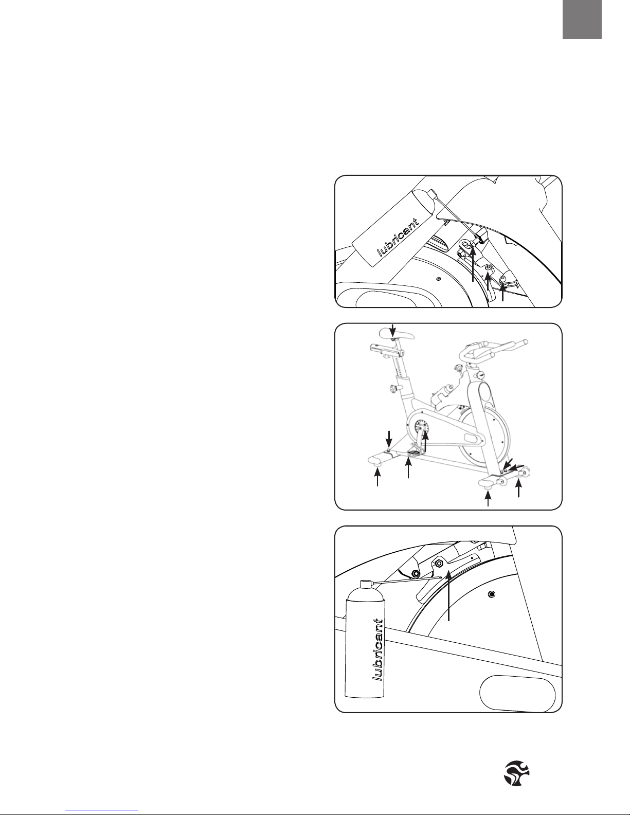
2. To maintain the easy adjustability of the
resistance system, the screw threads on the
lower end of the brake rod should be lubricated. First, turn the resistance knob clockwise
until it stops. Next, look under the right or
left side of the frame and locate the brake
rod (C). Apply a small amount of synthetic
grease (white lithium grease) to the thread on
the brake rod. Then, turn the resistance knob
counter-clockwise until it stops.
3. Some parts of the TOMAHAWK IC2 may
become loose as a result of repeated use.
Check pedals, toe clips, and pedal straps, and
make sure that they are properly tightened.
Next, check all exposed screws, bolts, and
nuts, and make sure that they are properly
tightened. Finally, check the saddle to make
sure that it is not lose damaged.
4. The brake pad will become worn as a
result of repeated use. The TOMAHAWK
IC2 should not be used if the emergency
braking system is not working properly
(see page 13)! Should you feel that the
resistance system’s functions are decient, it
is essential to ne-tune the resistance system
before the bike is used again! Please check
the setting of the brake system as follows:
First turn the resistance regulator on the
brake system as far as it will go to the left
(minimum braking eect). If the setting is
correct, the brake pads should be ush with
the ywheel and barely touching so that it’s
possible to cycle with a hardly noticeable
amount of resistance. The brake pad can
be adjusted using a 10 mm wrench. Next,
check the brake pad for signs of wear. If the
brake pad does show signs of excessive
wear, thoroughly soak the brake pad with
lubricant spray using the 2 lubrication
holes (B), and then wipe the excess o.
C
2.
3.
4.
B
Page 18
Version 1.1 2014 IC-TKIC2B-01 Copyright by Indoorcycling Group GmbH 2014 | www.indoorcycling.com
PREVENTIVE
MAINTENANCE
GRAPHICS ARE THE RIGHT SIDE
OF THE BIKE (RIDING POSITION)
D
D
B
C
C
A
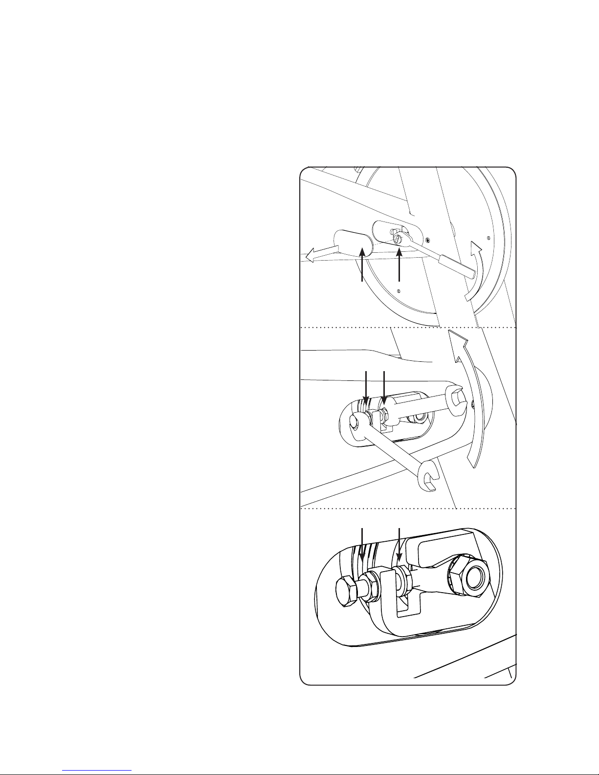
5. BELT DRIVE
Important: A loose belt as well as an
overtightened belt may cause injury of
the rider or damage to the drive system.
Checking belt tension: To check for a loose
belt, sit on the saddle, place your feet on the
pedals, move the pedals until the crank arms
are horizontal. Next, pull up the emergency
brake handle and hold it. Then, stand on the
pedals and rock forward and backward. There
should be no play or slip in the drive train.
If there is slip or play in the drive train, this
indicates that the belt is too loose.
Correct a slipping belt drive train: To adjust the belt,
pull o the right and the left maintenance covers (A).
Loosen the axle nut (B) on both ends of the ywheel
axle by two full turns. Loosen the inner adjustment nut
(D) facing the ywheel axle on each side of the ywheel.
Next, losen the lock nut (C).
Then, turn both (right and left sides) of the inner
adjustment nuts (D) on the intside of the ywheel
bracket ¼ of a turn at a time (upward on the R side and
downward on L side) until the belt is properly adjusted.
Make sure to turn both adjustment nuts exactly the
same amount to avoid misalignment of the ywheel.
Re-check if the amount of play or slip in the drive train
has disappeared.
Finally, retighten the two outer lock nuts (C) to secure the
new adjustment and retigthen the two axle nuts (B). At
last reattach the maintenance covers (A).
Check if belt drive is rmly tighten and does not slip
while riding under resistance load. In case that the belt
slips, proceed using the same technique as described
above. Please note that a belt drive gear never
shows slack. In case of adjustment do not apply
too much tension.
The manufacturer recommends using an ultrasonic
voltage meter adhering to a natural frequency of the belt
of 103 Hz ± 3 Hz. Ball bearing damage due to incorrect
belt tension is excluded from warranty.
5.
Page 19

19
ENG
MAINTENANCE ACTIVITY
REQUIRED SCHEDULE
EXAMPLES OF MAINTENANCE PLAN CHARTS FOR IN HOUSE SERVICE TECHNICIANS:
ACTIVITY ROTATION DETAILS
FEET LEVELLING, DISINFECTION
& CLEANING OF THE BIKE DAILY P 14
SERVICING BRAKE PADS, DETAILED
CLEANING OF THE ENTIRE BIKE WEEKLY P 14
CHECK EMERGENCY BRAKE FUNCTION BI-WEEKLY P 15
CLEAN AND LUBRICATE SADDLE
& HANDLEBAR SLIDERS / POSTS BI-WEEKLY P 15+16
CHECK ADJUSTMENT KNOBS MONTHLY P 16
CHECK BRAKE PAD FOR SIGNS OF WEAR MONTHLY P 17
CHECK BRAKE SYSTEM, LUBRICATE MONTHLY P 17
CHECK PEDALS, TOE CLIP & STRAPS MONTHLY P17
FOR SIGNS OF WEAR
CHECK ALL CONNECTIONS AND FIXINGS MONTHLY P17
CHECK BELT DRIVE TRAIN MOTHLY P18
WEEKLY MAINTENANCE CHECKLIST
BIKE NO. PRODUCTION CODE OBSERVATIONS ACTION TAKEN RESULT NAME/DATE
Page 20
Version 1.1 2014 IC-TKIC2B-01 Copyright by Indoorcycling Group GmbH 2014 | www.indoorcycling.com
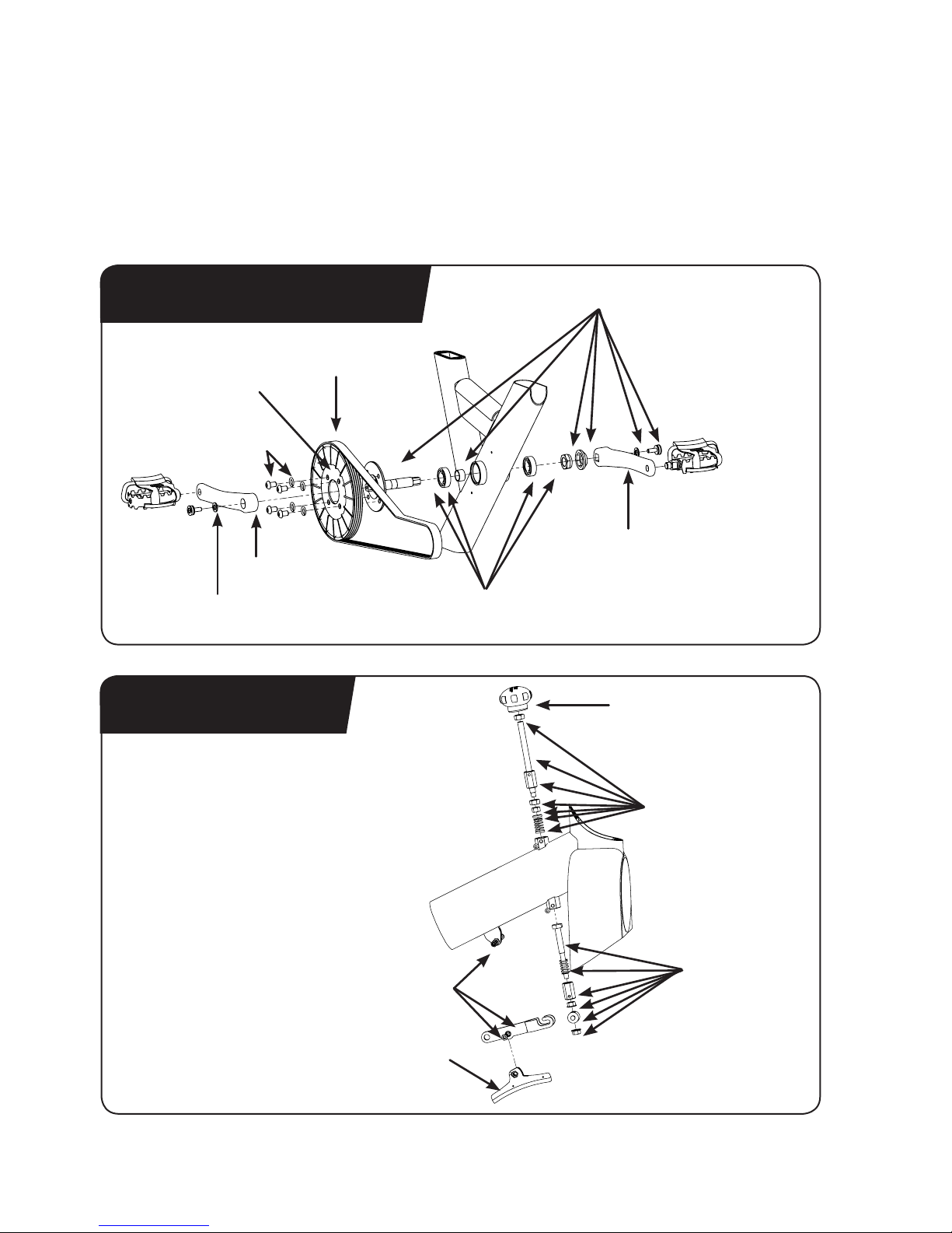
SPARE PARTS
DRIVE GEAR PARTS
BRAKE PARTS
02 50 A
02 50 06
130-01-00005-01
02 50 03 A
02 50 05
900-00-90008-20
150-03-00071-01
150-03-00008-01
150-03-00001-01
02 40 C MD20 08
150-03-00070-01
900-06-00001-01
150-03-00007-01
Page 21
21
ENG
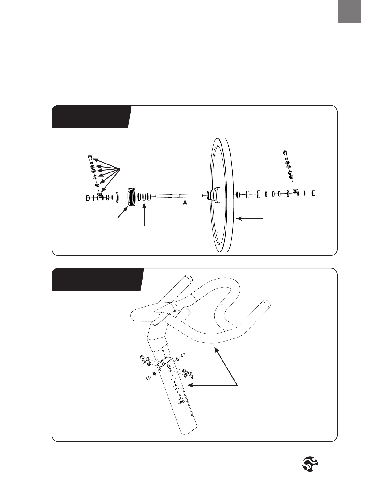
SPARE PARTS
FLYWHEEL
HANDLEBAR
900-06-00002-01
02 40 02
150-01-00051-01
02 30 01 AL
02 40 H150-01-00009-01
Page 22
Version 1.1 2014 IC-TKIC2B-01 Copyright by Indoorcycling Group GmbH 2014 | www.indoorcycling.com
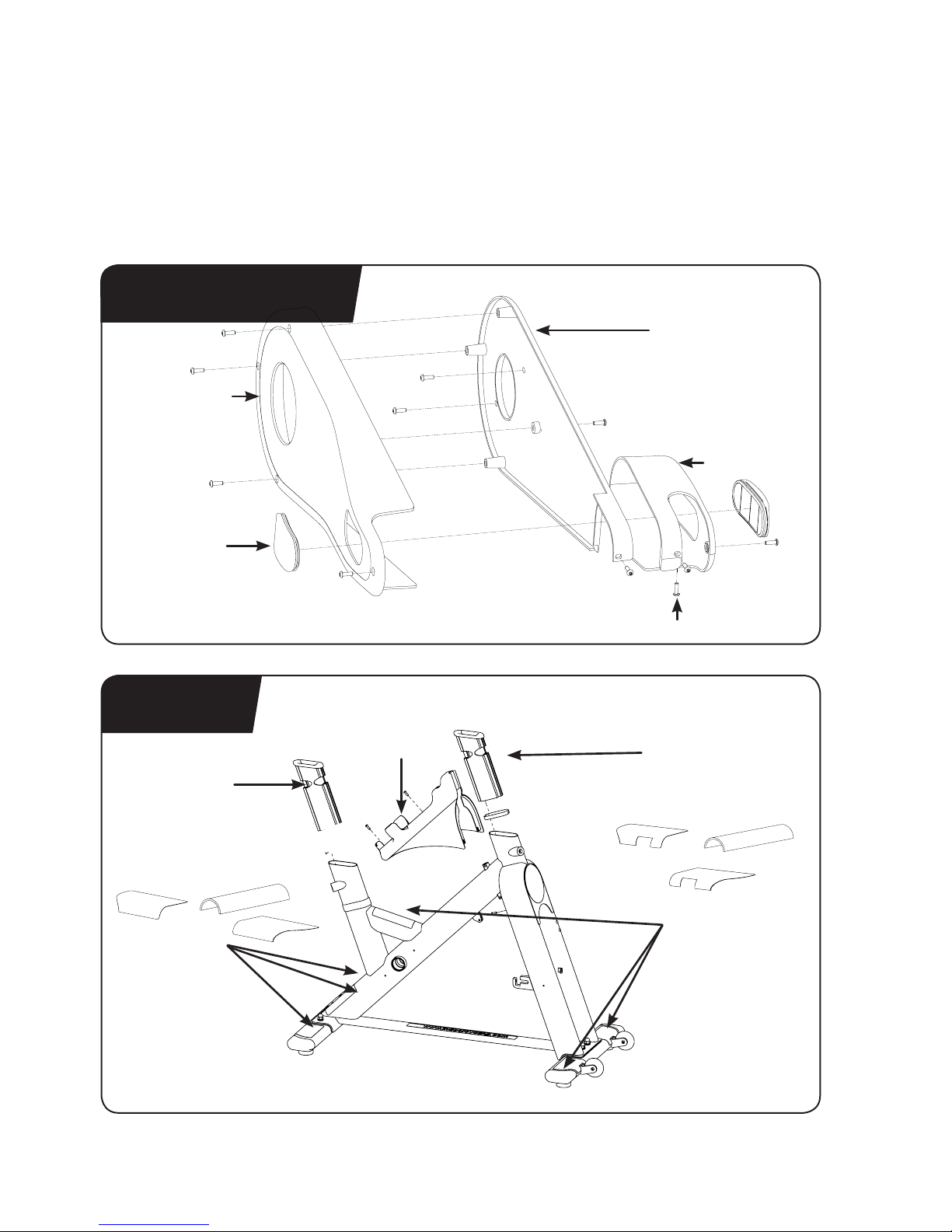
SPARE PARTS
CHAIN GUARD
FRAME
02 42 01 E 08
02 42 03 S E 12
02 99 03
02 42 02 E 12
02 42 04
02 10 A
02 99 02
02 10 A
02 99 11
(OPTIONAL)
02 99 10
(OPTIONAL)
DECAL SET 100-09-00021-01
Page 23
23
ENG
SPARE PARTS
POP PIN ADJUSTMENT KNOBS
02 99 02 10 HB
(OPTIONAL ITEM)
02 10 B 08
Page 24
Version 1.1 2014 IC-TKIC2B-01 Copyright by Indoorcycling Group GmbH 2014 | www.indoorcycling.com
SPARE PARTS
02 10 G
150-03-00048-01 (PAIR)
150-01-00005-01 (PAIR)
120-01-00002-01
120-01-00003-01
02 20 02
02 21 01 AL
(COMPLETE ASSEMBLY)
SADDLE SUPPORT
PEDALS
Page 25
25
ENG
SPARE PARTS
REAR STABILIZER
FRONT STABILIZER
02 11 05 B
02 11 E
140-02-00020-01
02 11 06
02 11 B
140-01-00003-01
140-02-00021-01
Page 26
Version 1.1 2014 IC-TKIC2B-01 Copyright by Indoorcycling Group GmbH 2014 | www.indoorcycling.com
WARRANTY
Indoorcycling Group GmbH warrants that all new equipment will be free of manufacturing defects in
workmanship and materials, becoming eective on the date of original installation. Parts repaired or
replaced under the terms of this warranty will be warrantedfor the remainder of the original warranty
period only. Warranty may vary by region or country. Please contact www.indoorcycling.com.
Defects caused by inappropriate use or handling of the product may cause
denegation of the manufacturers warranty.
Page 27

27
ENG
WARRANTY
10 YEARS WARRANTY: FRAME CONSTRUCTION AND WELDING
3 YEARS WARRANTY HANDLEBAR AND SADDLE ASSEMBLY, BRAKE SYSTEM
(EXCLUDING BRAKE PAD), LEVER HANDLES AND
KNOBS, CRANKS, BELT DRIVE SYSTEM, BOTTOM BRACKET
ASSEMBLY, FLYWHEEL AND HUB ASSEMBLY,
POWDER COATING OF FRAME PARTS.
2 YEARS WARRANTY : PEDALS, INSERT SLEEVES FOR HANDLE BAR
AND SADDLE POST, LEVELING FEET.
1 YEARS WARRANTY: SADDLE CONSTRUCTION
THE FOLLOWING WEAR ITEMS ARE EXCLUDED FROM WARRANTY:
Pedal straps, pedal binding system, water bottle holder.
Page 28

Version 1.1 2014 IC-TKIC2B-01 Copyright by Indoorcycling Group GmbH 2014 | www.indoorcycling.com
Manufactured by: Indoorcycling Group® GmbH
Happurger Str. 86 90482 Nuremberg Germany
EMAIL: INFO@INDOORCYCLING.COM
WEBSITE: WWW.INDOORCYCLING.COM
© 2014 Indoorcycling Group
CAUTION.
READ ALL PRECAUTIONS AND INSTRUCTIONS IN THIS MANUAL
BEFORE YOU BEGIN USING THIS EQUIPMENT. PLEASE KEEP
THIS MANUAL FOR FUTURE REFERENCE. IMPROPER ASSEMBLY,
SET UP, USE OR MAINTENANCE MAY VOID THE WARRANTY.
Page 29

DEU
HERSTELLER:
Indoorcycling Group GmbH
Happurger Str. 86
90482 Nuremberg | Germany
info@indoorcycling.com
www.indoorcycling.com
Phone: +49(0)911 / 54 44 50
IC2
MODELL NR:IC-TKIC2B-01
WICHTIGER HINWEIS!
BITTE LESEN SIE VOR DER INBETRIEBNAHME DES BIKES DIESES HANDBUCH VOLLSTÄNDIG
UND BEFOLGEN SIE ALLE DARIN BESCHRIEBENEN ANLEITUNGEN ZU MONTAGE,
WARTUNG UND BETRIEB DES GERÄTES NICHT ORDNUNGSGEMÄSSE HANDHABUNG
ODER UNZUREICHENDE WARTUNG FÜHRT ZUM ERLÖSCHEN DER GARANTIE!
Version 1.1 2014 IC-TKIC2B-01 Copyright by Indoorcycling Group GmbH 2014 | www.indoorcycling.com
Page 30

Version 1.1 2014 IC-TKIC2B-01 Copyright by Indoorcycling Group GmbH 2014 | www.indoorcycling.com
GEWICHT DES BIKES: 48 KG
MAXIMALES BENUTZERGEWICHT: 130 KG
BENUTZERGRÖSSE: GEEIGNET FÜR KÖRPERGRÖSSEN VON 150 – 205 CM
BENÖTIGTE STANDFLÄCHE: 53 X 115 CM
MAX. SATTEL UND LENKERHÖHE: CA. 116 CM / 119 CM
TECHNISCHE DATEN:
Das Tomahawk IC2 Bike entspricht nach EN 957 der Benutzerklasse S und ist für
die Verwendung in kontrollierter Umgebung wie z.B. Sportstätten und Fitnesseinrichtungen
unter Beaufsichtigung eines Trainers klassiziert.
WICHTIG!
Dieses Produkt ist nicht für den gewerblichen Gebrauch in Sport- und Fitnesseinrichtungen
konzipiert. Beim gewerblichen Einsatz des Gerätes verfallen sämtliche Garantieansprüche.
INHALTSVERZEICHNIS
WICHTIGE SICHERHEITSHINWEISE P.3
EINFÜHRUNG P.4
MONTAGE UND ZUSAMMENBAU P.5-7
INSTALLATION, AUFBAU P.8-9
RICHTIGE RADEINSTELLUNG P.10-12
WIDERSTANDSEINSTELLUNG P.13
AUFSTELLEN UND BEWEGEN DES RADES P.13
REGELMÄSSIGE WARTUNGS- UND PFLEGEMASSNAHMEN P.14-17
RIEMENSPANNUNG PRÜFEN UND EINSTELLEN P.18
WARTUNGS- UND PFLEGEPLAN P.19
ERSATZTEILE P.20-25
GARANTIE P.26-27
Page 31

3
DEU
1. Es liegt in der alleinigen Verantwortung des
Eigentümers, alle Nutzer über die sachgerechte
und ordnungsgemäße Verwendung zu
informieren und erst nach erfolgter Einweisung
durch einen qualizierten Trainer oder
Instruktor die eigenständige Nutzung des Bikes
zu autorisieren ( siehe Seite 10-13).
2. Benutzen Sie das Bike erst nach
ordnungsgemäßer Montage und deren
Überprüfung wie auf den
Seiten 5-9 beschrieben.
3. Verwenden Sie das Bike nicht im Freien und
setzen Sie es nach Möglichkeit keiner feuchten
und/oder staubigen Umgebung aus. Das Gerät
wurde für die Verwendung in geschlossenen
Räumen konzipiert.
4. Platzieren Sie das Bike immer auf einem
standsicheren, ebenen und zugleich
horizontalen Untergrund. Falls Sie das Bike
auf Teppich- oder Parkettböden platzieren,
empehlt es sich eine Unterlegmatte zu
verwenden, um eventuellen Beschädigungen
des Bodenbelags vorzubeugen.
5. Bitte führen Sie alle in diesem Handbuch
beschriebenen Pege-, Wartungs- und
Servicearbeiten regelmäßig durch. Defekte
Teile sind umgehend zu ersetzen und das Gerät
bis zur erfolgten Instandsetzung nicht mehr
zu benutzen. Verwenden Sie ausschließlich
Ersatzteile des Herstellers.
6. Kindern unter 14 Jahren ist es nicht erlaubt,
das Bike ohne Aufsicht durch einen dazu
qualizierten Instruktor oder
Trainer zu verwenden.
7. Das Bike ist für ein maximales
Benutzergewicht von 130 kg ausgelegt.
Das Bike sollte nicht von Personen
benutzt werden, die dieses max. zulässige
Benutzergewicht überschreiten.
8. Es ist darauf zu achten, nur mit eng
anliegender Rad- oder Sportbekleidung zu
fahren und festes Schuhwerk, vorzugsweise
Radschuhe, zu tragen. Lose Schnürsenkel
können sich im Antriebssystem verfangen und
zu Verletzungen führen. Verstellvorrichtungen
sollten nicht hervorstehen, um die
Bewegungsfreiheit des Nutzers nicht
zu behindern.
9. Das Bike verfügt über keinen Freilauf. Die
Pedale sind über den Antrieb direkt mit dem
Schwungrad verbunden. Die Bewegung kann
nur durch Betätigen der Notbremse oder
durch kontrolliertes Reduzieren der
Trittfrequenz gestoppt werden.
10. Aus Gründen der Benutzersicherheit sollte
niemals komplett ohne Bremswiderstand
gefahren werden.
11. Bei Schwindelgefühl oder Übelkeit sollte
das Training sofort unterbrochen werden.
Es empehlt sich einen Arzt zu konsultieren,
falls sich dieses Unwohlsein nicht
kurzfristig bessert.
WICHTIGE
SICHERHEITSHINWEISE
WARNUNG!
Um einem Sicherheitsrisiko durch unsachgemäße
Handhabung des Gerätes vorzubeugen ist es
erforderlich, die nachfolgenden Sicherheitshinweise
und Informationen vor der Inbetriebnahme des
Gerätes im Detail zu lesen und zu beachten!
WICHTIGER HINWEIS:
Falls Sie gesundheitliche Probleme haben oder
vorbelastet sind, empfiehlt es sich einen Arzt zu
konsultieren, um die für Sie am besten geeignete
Trainingsmethode zu finden. Zu hohe Trai-
ningsbelastung oder Intensität sowie die unsachgemäße
Nutzung des Bikes kann zu gesundheitlichen Schäden
und ernsthaften Verletzungen führen.
Der Hersteller übernimmt ausdrücklich keine Verantwortung für
gesundheitliche Risiken, Schäden oder Folgeschäden die durch die
Benutzung dieses Gerätes entstehen können insofern es sich
hierbei nicht um Folgeerscheinungen handelt, die auf Materialund /oder Herstellungsmängel zurückzuführen sind und in der
Verantwortung des Herstellers liegen.
Page 32

Version 1.1 2014 IC-TKIC2B-01 Copyright by Indoorcycling Group GmbH 2014 | www.indoorcycling.com
SEHR GEEHRTER KUNDE,
wir möchten uns für Ihr Vertrauen und Ihre Kaufentscheidung bedanken. Mit dem
Tomahawk Indoor Cycle haben Sie sich für ein Qualitätsprodukt entschieden, das nach
den neuesten technischen Erkenntnissen entwickelt und somit auf höchste Beanspruchung
und Zuverlässigkeit ausgelegt wurde.
Dieses Höchstmaß an Zuverlässigkeit lässt sich jedoch nur über eine regelmäßige Pege
und Wartung sicherstellen. Bei entsprechender Einhaltung der in diesem Handbuch
beschriebenen Maßnahmen, wird eine maximale Standfestigkeit und Lebensdauer bei
minimalem Wartungsaufwand an den Tag gelegt und garantiert Ihnen einen langjährigen,
störungsfreien Betrieb.
DEN PRODUKTIONSCODE FINDEN SIE AUF DER LINKEN SEITE DES INDOOR CYCLES IM UNTEREN BEREICH DES RAHMENS.
EINFÜHRUNG
NOTBREMSGRIFF & WIEDERSTANDSEINSTELLUNG
SATTEL
T- FESTSTELLGRIFF
ARRETIERGRIFF
KOMBIPEDAL
KETTENKASTEN
SERVICEABDECKUNG
LENKER
ARRETIERGRIFF
BREMSBELAG
SCHWUNGSCHEIBE
TRANSPORTROLLE
STANDFUSS
Page 33

5
DEU
MONTAGE UND
ZUSAMMENBAU
SW 17/19MM
SW 13/15MM
15MM
PEDALSCHLÜSSEL
2X 1X
3MM
6MM
HANDFEST
ANZIEHEN
1. 2.
4.3.
BITTE STELLEN SICH SICHER, DASS DIE
PLASTIKDICHTUNG ZWISCHEN DEM STABILISATOR
UND DEM RAHMENTRÄGER PLATZIERT IST.
BITTE STELLEN SICH SICHER, DASS DIE
PLASTIKDICHTUNG ZWISCHEN DEM STABILISATOR
UND DEM RAHMENTRÄGER PLATZIERT IST.
DIE SCHWARZE KUNSTSTOFFBEILAGSCHEIBE MUSS
ZWISCHEN DEM RAHMENTRÄGER UND DER
EDELSTAHLBEILAGSCHEIBE PLATZIERT SEIN.
DIE SCHWARZE KUNSSTOFFBEILAGSCHEIBE MUSS
ZWISCHEN DEM RAHMENTRÄGER UND DER
EDELSTAHLBEILAGSCHEIBE PLATZIERT SEIN.
Page 34

Version 1.1 2014 IC-TKIC2B-01 Copyright by Indoorcycling Group GmbH 2014 | www.indoorcycling.com
WICHTIG!
Sattel in vertikaler und horizontaler Position ausrichten!
13mm Mutter der Sattelklemme ausreichend fest von
beiden Seiten aus anziehen!
MONTAGE UND
ZUSAMMENBAU
5. 6.
7.
STOP MARKIERUNG
SW 17/19MM
SW 13/15MM
15MM
PEDALSCHLÜSSEL
2X 1X
3MM
6MM
HANDFEST
ANZIEHEN
WICHTIG!
Das mit R markierte Pedal am rechten Kurbelarm
montieren und in Uhrzeigerrichtung festziehen
(standard Rechtsgewinde). Das mit L markierte Pedal
am linken Kurbelarm montieren und gegen die
Uhrzeigerrichtung festziehen (Linksgewinde). Bitte
darauf achten, dass beide Pedale mit ausreichender
Festigkeit montiert werden um einem Lösen der
Schraubverbindung während des Betriebes vorzubeugen.
Page 35

7
DEU
MONTAGE UND
ZUSAMMENBAU
8.
10. 11.
9.
STOP MARKIERUNG
STOP MARKIERUNG
STOP MARKIERUNG
SW 17/19MM
SW 13/15MM
15MM
PEDALSCHLÜSSEL
2X 1X
3MM
6MM
HANDFEST
ANZIEHEN
Page 36

Version 1.1 2014 IC-TKIC2B-01 Copyright by Indoorcycling Group GmbH 2014 | www.indoorcycling.com
INSTALLATION, AUFBAU
TOMAHAWK BIKES
Die Einstellungen müssen bei der Erstinstallation der TOMAHAWK Bikes vorgenommen
werden, um eine optimale Leistung und lange Lebensdauer zu gewährleisten. Bitte
lesen und befolgen Sie die folgenden Anleitungen genau. Wenn die Bikes nicht wie
beschrieben installiert und eingestellt werden, können die Komponenten einem
übermäßigen Verschleiß ausgesetzt sein und die Bikes beschädigt werden. Bei
Fragen zur Installation wenden Sie sich bitte an service@indoorcycling.com.
Hinweis: Für manche Wartungsverfahren werden Schmierstoe benötigt.
Bitte verwenden sie ausschließlich einen lösungsmittel-, silikon- und
säurefreien Sprühschmiersto (z.B. Brunox) und weißes Lithiumfett.
1. Bitte sicherstellen, dass die Bikes gerade stehen. Wenn das TOMAHAWK Bike wackelig auf
dem Boden steht, drehen Sie die verstellbaren Füße unter dem vorderen und/oder hinteren
Stabilisator solange, bis die Schaukelbewegung aufhört. Stellen Sie sicher, dass die Standfüße
nicht weiter als 10mm herausgedreht sind.
2. Überprüfen Sie die Notbremsfunktion auf korrekte Funktionsweise.
3. Kalibrierung des Bremssystems: Drehen Sie den Widerstandsknopf so weit wie möglich
gegen den Uhrzeigersinn (Mindestbremswirkung) und stellen Sie sicher, dass ein leichter
Abstand zwischen Bremsklotz und Schwungrad besteht. Der Bremsklotz sollte das
Schwungrad ganz leicht berühren, wenn der Widerstandsknopf so weit wie möglich gegen den
Uhrzeigersinn gedreht ist.
4. Unbedingt den Sprühschmiersto üppig auf den Bremsklotz auftragen. Verwenden Sie
dafür die Schmierlöcher auf der Kunststohalterung des Bremsbelags oder sprühen Sie
direkt von außen auf den Filzbelag. Stellen Sie sicher, dass der Bremsklotz rundherum gut mit
Sprühschmiersto getränkt ist. Anschließend überschüssige Rückstände vom Schwungrad
abwischen.Tipp: Benutzen Sie eine wiederauüllbare Sprühasche und füllen diese mit
treibmittel- und säurefreien Schmiersto um die Umwelt nicht unnötig zu belasten.
5. Lithiumfett auf die Metallgewinde am unteren Ende der Bremszugstange geben. Hierfür
zuerst den Widerstandsknopf im Uhrzeigersinn drehen, bis er stoppt. Lithiumfett in geringer
Menge auf die Gewinde an der Bremszugstange oberhalb der beiden Nutmuttern geben. Dann
den Widerstandsknopf gegen den Uhrzeigersinn drehen, bis er stoppt.
Page 37

9
DEU
INSTALLATION, AUFBAU
TOMAHAWK BIKES
6. Lithiumfett auf die Metallgewinde aller Justierknöpfe geben.
7. Überprüfen Sie die vier (4) Inbusmuttern auf der Riemenscheibe auf festen Sitz. Sind sie locker,
Gewindekleber LocTite Threadlocker Blue-243 auftragen und wieder fest anziehen.
8. Überprüfen Sie die die beiden Inbusschrauben, mit welchen die Tretkurbeln (an der
rechten und linken Seite des Tretlagers) befestigt sind, auf festen Sitz. Sollten diese locker sein,
Gewindekleber LocTite Threadlocker Blue-243 auf die Schraubengewinde leicht auftragen und
wieder fest anziehen.
9. Überprüfen Sie die Riemenspannung. Prüfen Sie, ob der Riemenantrieb fest angezogen ist
und beim Fahren unter Belastungswiderstand nicht verrutscht. Verrutscht der Riemen, müssen
die Justieranweisungen durchgeführt werden, die auf Seite 18 beschrieben ist.
10. Lappen mit Sprühschmiersto befeuchten und Rahmen abwischen.
11. Einige Teile des Bikes können sich während des Transportes lösen. Überprüfen Sie die
Kurbelscheibe und alle sichtbaren Schrauben, Bolzen und Muttern. Stellen Sie sicher, dass sie
diese festsitzen und angezogen sind.
KUNDENDIENST
1. Geben Sie dem Kunden die Anleitungen für die Grundwartung und verweisen Sie ihn auf die
ausführlichen Wartungsanleitungen (Seite 14-19).
2. Zeichnen Sie das Blatt ab, das dem Kunden übergeben wurde, um die Erklärung der
Wartungsverfahren/Handbuch und Zustandsüberprüfung der Bikes zu bestätigen.
Page 38

Version 1.1 2014 IC-TKIC2B-01 Copyright by Indoorcycling Group GmbH 2014 | www.indoorcycling.com
Das Tomahawk Bike kann sehr variabel, entsprechend den Bedürfnissen verschiedener
Benutzergruppen, eingestellt werden. Dadurch wird optimaler Fahrkomfort unter Berücksichtigung einer für diesen Zweck idealen Körperhaltung gewährleistet. Somit können optimale
Trainingsergebnisse erzielt werden. Die nachfolgend beschriebenen Möglichkeiten
zeigen nur einige der meist verwendeten Einstellvarianten des Bikes. Es obliegt dem
Benutzer, eine für ihn ideale Fahrposition einzustellen.
SITZHÖHENEINSTELLUNG:
Setzen Sie sich auf den Sattel und stellen Sie sicher, dass Ihr Becken nicht nach einer
Seite gekippt ist wenn das Pedal die im Bild gezeigte Stellung eingenommen hat.
Platzieren Sie Ihre Schuhe in den Schuhkörben der Pedale oder bei Verwendung von
Radschuhen im Bindungssystem, falls Ihr Bike mit einem Kombipedalsystem ausgerüstet ist.
RICHTIGE
RADEINSTELLUNG
Vertikale
Lenkerverstellungnicht
über die STOP-Markierung
hinaus in der Höhe
verstellen (siehe Seite 7).
WICHTIG!
Bitte sicherstellen, dass der Sicherheitsrastbolzen der Arretiergrie eingerastet ist . Den Arretiergri handfest anziehen um
ein Wackeln der vertikalen Sattel- und Lenkerverstellung im Rahmen zu verhindern. Zu festes Anziehen der Arretiergrie
ist zu vermeiden und kann zu Beschädigungen an den Aluminuimteilen der vertikalen Lenker und Sattelrohre führen.
Fangen Sie langsam an zu treten, bis das Pedal die im Bild gezeigte Position erreicht hat. Die vertikale Sattelstütze sollte
jetzt so eingestellt sein, dass die Knie immer beim Erreichen dieser Pedalstellung leicht abgewinkelt sind, ohne dass das
Becken nach einer Seite kippt. Als Faustregel gilt wenn Sie neben dem Bike stehen: Eine Handbreit oder 4 Finger
unterhalb des Beckenkamms. Bitte vermeiden Sie, mit durchgestreckten Knien oder
kippendem Becken zu fahren.
Vertikale Sattelverstellung nicht über
die STOP-Markierung hinaus in der
Höhe verstellen (siehe Seite 6).
1) Lösen der
Stützverstellung:
Einstellknopf gegen
Uhrzeigersinn drehen
2) Höhenverstellung
der Stütze: Ziehen des
Einstellknopfes,
selbstständiges
Einrasten (hörbar)
3) Fixieren der
Stützverstellung:
Einrasten des
Einstellknopfes und
im Uhrzeigersinn
festdrehen
Page 39

11
DEU
HORIZONTALE SATTELEINSTELLUNG:
Die horizontale Positionierung des Sattels ist sehr wichtig, um Verletzungen an den
Kniegelenken vorzubeugen. Setzen Sie sich auf den Sattel und bringen Sie die Kurbelarme
in die horizontale Position.
Das Kniegelenk am nach vorne gerichteten Bein sollte sich direkt über der Achse des Pedals benden. Falls dies nicht der
Einstellung Ihres Bikes entspricht, justieren Sie bitte die horizontale Sattelverstellung nach vorne oder hinten um diese
Sitzposition zu erreichen.
RICHTIGE
RADEINSTELLUNG
Horizontale
Sattelverstellung
mittels T-Feststellgri
Page 40

Version 1.1 2014 IC-TKIC2B-01 Copyright by Indoorcycling Group GmbH 2014 | www.indoorcycling.com
RICHTIGE
RADEINSTELLUNG
Als Nächstes sollte die Position des Lenkers möglichst genau auf Ihre Körpergröße eingestellt
werden. Hierzu winkeln Sie bitte Ihren Arm an und berühren mit dem Ellenbogen das vordere
Ende des Sattels. Bei ausgestrecktem Unterarm sollte nun die Spitze Ihres Mittelngers den
Mittelpunkt des Lenkers berühren. Eine für ungeübte Fahrer ideale und schonende Sitzposition
ist erreicht, wenn Ihr Rücken eine Neigung in einem Winkel von 45° hat.
Der Lenker oeriert vielfältige Handpositionen und Einstellmöglichkeiten, die es dem geübten Fahrer leicht machen,
seine ideale Sitz- und Handpositionierung zu nden. Es wird empfohlen während längerer Trainingseinheiten
die Handposition regelmäßig zu wechseln, um einseitige und monotone Belastungen der Muskeln, Bänder
und Gelenke zu vermeiden.
LENKERPOSITIONIERUNG:
Zu Beginn der Einstellung sollte bei ungeübten Benutzern der Lenker in gleicher Höhe mit dem
Sattel eingestellt sein (Linie A) und sich auf der „0“ Markierung (Linie B) benden. Wenn die Knie
beim stehenden Fahren den Lenker berühren oder diese Sitzposition bei längerem Fahren unbequem ist, sollte zunächst der Lenker etwas höher eingestellt werden. Lenker in der Vertikalen
niemals über die STOP-Markierung hinaus in der Höhe verstellen.
A.
B.
Verstellknopf zur
Höhenverstellung des
Lenkers. Zur Handhabung
des Knopfes lesen Sie
bitte unbedingt Seite 10!
Page 41

13
DEU
RICHTIGE HANDHABUNG
DES BIKES
EINSTELLUNG DES WIDERSTANDES:
Der individuell angestrebte Bremswiderstand kann mit Hilfe des Bremsverstellknopfes
fein und stufenlos eingestellt werden. Um den Bremswiderstand zu erhöhen, wird der
Bremsverstellknopfes im Uhrzeigersinn gedreht. Um den Bremswiderstand zu verringern wird
gegen den Uhrzeigersinn gedreht.
Bitte niemals unter Widerstandsbelastung rückwärts fahren, da sich die Schraubverbindung der Pedale zum Kurbelarm
lockern kann und ein Lösen der Verbindung nicht auszuschließen ist. Um die Schwungscheibe während des Betriebs zu
stoppen muss der Bremsknopf gedrückt werden. Während des Trainings ist darauf zu achten dass die Schuhe in
den dafür vorgesehenen Fußkörben platziert oder bei Verwendung von Radschuhen mit dem Bindungssystem
verbunden sind.
AUFSTELLEN DES INDOOR CYCLES:
Es empehlt sich, das Indoor Cycle mit zwei Personen zu bewegen. Um Unfällen vorzubeugen und Beschädigungen an den Einschubbuchsen des Lenkers zu vermeiden
ist es notwendig, dass die vertikale Lenkerverstellung fest xiert wurde, bevor Sie das Rad
kippen. Bitte seien Sie besonders vorsichtig wenn Sie das Indoor Cycle über einen
unebenen Boden bewegen. Hier empehlt sich eine 2. Person, die das eventuelle Kippen
zur Seite verhindert. Weiterhin ist darauf zu achten einen Sicherheitsabstand von
mindestens 50 cm zu anderen Geräten einzuhalten.
Überprüfen Sie die Standsicherheit des Indoor Cycles am
Einsatzort und justieren Sie ggf. die niveauregulierbaren
Stellfüße auf der Unterseite der Stabilisatoren, um die
gewünschte Standsicherheit zu gewährleisten.
WICHTIG!
Die Standfüße sollten immer möglichst weit hinein
gedreht werden. Nicht mehr als ca. 1cm herausdrehen!
STANDFÜSSE
Das Indoor Bike verfügt über keinen Freilauf. Die Schwungscheibe ist fest mit den Pedalen verbunden und stoppt nicht
selbstständig, wenn der Benutzer die Tretbewegung unterbricht. Bitte kontrollieren Sie immer Ihre Bewegungen und
verlangsamen Sie diese kontrolliert um anzuhalten oder drücken Sie den roten Notbremsknopf einfach nach unten
um die Bewegung schnell zu verlangsamen , damit die Schwungscheibe zum Stehen kommt, um das Training zu
unterbrechen. NOTBREMSE = BREMSKNOPF NACH UNTEN DRÜCKEN.
NOTBREMSSYSTEM: ROTEN BREMSKNOPF DRÜCKEN
WIDERSTANDSREGLER: ROTEN BREMSVERSTELLKNOPF DREHEN
Aus Sicherheitsgründen ist darauf zu achten immer unter kontrollierter Bewegung
zu fahren und die Trittfrequenz dem fahrerischen Fähigkeiten anzupassen.
Page 42

Version 1.1 2014 IC-TKIC2B-01 Copyright by Indoorcycling Group GmbH 2014 | www.indoorcycling.com
WARNUNG!
Die nachfolgenden Wartungs- und Pegemaßnahmen müssen in der beschriebenen Regelmäßigkeit durchgeführt werden, um ein Höchstmaß an Betriebssicherheit und Lebensdauer zu
gewährleisten. Bitte befolgen Sie die nachfolgenden Anweisungen gewissenhaft. Nicht regelmäßig durchgeführte Wartungs- und Pegearbeiten führen zu erhöhtem Verschleiß am Produkt
und zum Erlöschen der Garantieleistungen. Falls Sie weitere Fragen zu diesem Thema haben,
wenden Sie sich bitte an unseren technischen Support.
Bitte verwenden Sie ausschließlich die von uns empfohlenen lösungsmittel-, silikon- und säurefreien Wartungs- und Pegemittel (z.B. Brunox), um Beschädigungen an den Komponenten des
Indoor Cycles vorzubeugen.
TÄGLICHE MASSNAHMEN:
1. Prüfen des Indoor Cycles auf Standsicherheit. Ggf. wie auf S.13 beschrieben justieren.
2. Das regelmäßige Reinigen des Indoor Cycles muss aus hygienischen Gründen nach jeder Be-
nutzung durchgeführt werden. Sorgen Sie auch dafür, dass ausreichend weiche Lappen oder
Zellstotücher sowie Wartungs- und Desinfektionsmittel bereit stehen. Desinzieren Sie zuerst
den Sattel und Lenker mit einem dafür geeigneten Mittel und reinigen Sie danach das gesamte
Indoor Cycle von Körperschweißrückständen.
WÖCHENTLICHE MASSNAHMEN:
1. Reinigung: Je nach Nutzung des Gerätes ist es erforderlich, mindestens einmal pro
Woche eine detaillierte Reinigung des Indoor Cycles durchzuführen. Hierzu sprühen Sie bitte
Wartungsspray auf einen weichen Lappen und reinigen Sie alle Plastikteile, die komplette
Schwungscheibe und den kompletten Rahmen.
2. Bremsbelag: Um eine optimale Funktion
aufrecht zu erhalten und den Verschleiß
der Bremsbeläge zu minimieren, muss der
Bremsbelag mit Wartungsspray behandelt
werden. Hierzu sprühen Sie das Wartungsspray in die dafür vorgesehenen Löcher, bis
sich der Bremsbelag vollgesogen hat. Fusselige Bremsbeläge oder ungleichmäßiger
Widerstand sind eindeutige Zeichen für zu
trockene Bremsbeläge.
REGELMÄSSIGE PFLEGE
UND WARTUNG
Page 43

15
DEU
14-TÄGIGE MASSNAHMEN:
1. Notbremse: Aus Gründen der Betriebs-
sicherheit muss die Notbremse regelmäßig
auf ihre Funktion überprüft werden. Hierzu
drücken Sie während des Fahrens den roten
Notbremsknopf nach unten. Bei optimaler
Funktion sollte es zu einer sofortigen Bremswirkung bis hin zum vollständigen Stillstand
der Schwungscheibe kommen.
2. Sattelverstellungen: Um die
Leichtgängigkeit zu gewährleisten, muß
die vertikale und horizontale Sattelstütze
regelmäßig gereinigt und eingefettet
werden. Hierzu nehmen Sie die komplette
vertikale Sattelstütze (A) aus ihrer Führung,
sprühen diese mit Wartungsspray ein und
reiben die gesamten Außenächen inklusive
der horizontalen Verstellung mit einem
weichen Lappen ab.
Bevor Sie diese wieder in das Rahmenrohr einsetzen,
sprühen Sie ausreichend Wartungsspray gleichmäßig in
die Kunststoführungsbuchsen um die Leichtgängigkeit
der vertikalen Verstellung zu gewährleisten.
Reinigen Sie die Kontaktächen (B) der horizontalen
Sattelverstellung vorher von Schweißrückständen und
sprühen Sie diese ebenfalls gleichmäßig
mit Wartungsspray ein.
A
B
REGELMÄSSIGE PFLEGE
UND WARTUNG
1.
2.
Page 44

Version 1.1 2014 IC-TKIC2B-01 Copyright by Indoorcycling Group GmbH 2014 | www.indoorcycling.com
3. Lenker: Um die Leichtgängigkeit der
Lenkerverstellung zu gewährleisten, muss die
vertikale und - falls vorhanden - die horizontale Lenkerverstellung (optionales Zubehör
horizontal verstellbarer Lenker) regelmäßig
gereinigt und eingefettet werden. Hierzu
nehmen Sie den kompletten Lenker (A) aus
seiner Führung, sprühen diesen mit Wartungsspray ein und reiben die gesamten
Außenächen inklusive der horizontalen
Verstellung mit einem weichen Lappen ab.
Bevor Sie den Lenker wieder in das Rahmenrohr
einsetzen, sprühen Sie ausreichend Wartungsspray
gleichmäßig in die Kunststoführungsbuchsen,
um die Leichtgängigkeit der vertikalen
Verstellung zu gewährleisten.
MONATLICHE MASSNAHMEN:
1. Arretier- und Feststellgrie: Um die ein-
wandfreie Funktion für die horizontale und
vertikale Sattel- und Lenkereinstellung (A)
in vollem Umfang zu gewährleisten, müssen
die Gewinde sowie die Gewindeeinsätze mit
Wartungsspray eingesprüht werden.
REGELMÄSSIGE PFLEGE
UND WARTUNG
1.
A
A
3.
Page 45

17
DEU
2. Bremssystem: Um eine dauerhaft
einwandfreie und optimale Funktion sicher
zu stellen, ist es erforderlich, die gesamte
Bremsmechanik (C),welche sich unterhalb
des Schwitzschutzes und teilweise innerhalb
des Rahmens bendet, mit Gewindefett oder
Wartungsspray zu behandeln. Es ist vor allem
darauf zu achten, dass die Gewinde über die
gesamte Länge nicht trocken laufen, da dies
zu extremem Verschleiß führen kann.
3. Verbindungselemente: Im Rahmen
der regelmäßigen Wartungs– und
Pegemaßnahmen sollten alle Schrauben,
Muttern u.s.w. am Indoor Cycle auf festen Sitz
und Funktion überprüft werden und Teile die
Verschleiß, Abnutzung oder Beschädigung
zeigen (Bremsbeläge, Sattel, Pedalriemen,
Pedale, SPD System) ersetzt werden.
4. Bremsbelag: Abhängig von der
regelmäßigen und ordnungsgemäßen
Durchführung der Pegemaßnahmen
wird der Bremsbelag früher oder später
Verschleißerscheinungen aufzeigen und
muss ersetzt werden. Das Indoor Cycle
sollte nicht benutzt werden, wenn die
Notbremsfunktion (siehe Seite 13/15) nicht
mehr 100%ig gewährleistet ist. Ist dies der
Fall, kann das Bremssystem entsprechend
neu kalibriert werden. Bitte wenden Sie
sich für detaillierte Informationen und
Auskünfte an unseren technischen Support.
Wenn die Bremsbeläge erste Anzeichen von
erhöhtem Verschleiß (Fusseln) zeigen ist das
ein eindeutiges Zeichen, dass diese nicht
ausreichend mit Wartungsspray behandelt
wurden. Warten Sie die Bremsbeläge,indem
Sie Wartungsspray in die dafür vorgesehenen
Wartungsönungen (B) am Bremsbelag
sprühen (Seite 14).
C
REGELMÄSSIGE PFLEGE
UND WARTUNG
2.
3.
4.
B
Page 46

Version 1.1 2014 IC-TKIC2B-01 Copyright by Indoorcycling Group GmbH 2014 | www.indoorcycling.com
DIE DARSTELLUNG IN DEN
PIKTOGRAMMEN ZEIGEN DIE RECHTE
SEITE DES BIKES IN FAHRTRICHTUNG.
D
D
B
C
C
A
WICHTIG!
Der Riemenantrieb darf aus Sicherheitsgründen unter normalen Nutzungsbedingungen
nicht durchrutschen. Es ist darauf zu achten
das die Riemenspannung gemäß den Herstellervorgaben akkurat eingehalten wird.
Zu hohe Riemenspannung führt zu einem
erhöhten Verschleiß an den Schwungscheiben und Tretlagern was die Lebensdauer
negativ beeinusst. Der Hersteller empehlt
die Verwendung eines Ultraschall Spannungsmessgerätes sowie die Einhaltung
einer Eigenfrequenz des Riemens von 103 Hz
+/- 3 Hz. Kugellagerschäden aufgrund falsch
eingestellter Riemenspannung sind von der
Garantieleistung ausgeschlossen.
Ein zu loser Riemen kann beim Fahren durchrutschen
und zu erheblichen Verletzungen des Fahrers führen.
Zum Überprüfen der Riemenspannung bringen Sie die
Pedalarme in eine waagerechte
Position. Betätigen Sie das Notbremssystem und wippen
Sie (stehend auf den Pedalen) vor und
zurück. Die Pedale sollten bei korrekter Riemenspannung
kein Spiel zeigen.
Falls der Riemen durchrutschen sollte, verfahren Sie wie
folgt um die Riemenspannung entsprechend zu justieren.
Entfernen Sie die Abdeckkappen (A) und lockern Sie
die Achsmuttern (B) (17mm) auf beiden Seiten der
Schwungscheibe. Als nächstes lösen Sie bitte die Sicherungsmuttern (C) auf beiden Seiten der Achsaufnahme.
Zum gleichmäßigen spannen des Riemens ist darauf zu
achten das die Justiermuttern (D) auf beiden Seiten der
Achsaufnahme gleichmäßig festgezogen werden. Meist
genügt schon eine 1/2 Umdrehung um den gewünschten
Eekt zu erzielen. Ungleichmäßiges Anziehen der Justierschrauben führt zur Fehlausrichtung der Schwungscheibe und macht sich durch einen erhöhten Verschleiß der
Schwungscheibenlager bemerkbar.
Nach erfolgter Einstellung der Riemenspannung ziehen
Sie die beiden Sicherungsmuttern fest und stellen Sie
sicher das die Achsmuttern festgezogen sind.
5.
RIEMENSPANNUNG
PRÜFEN UND EINSTELLEN
Page 47

19
DEU
WARTUNGS- UND
PFLEGEPLAN
BEISPIEL FÜR EINEN WARTUNGSPLAN BEI DURCHFÜHRUNG DER ARBEITEN DURCH DRITTE.
TÄTIGKEIT TURNUS DETAILS
REINIGUNG UND DESINFEKTION SOWIE
STANDSICHERHEIT DES BIKES PRÜFEN TÄGLICH SEITE 14
WARTUNG DER BREMSBELÄGE UND
DETAILREINIGUNG DES GESAMTEN BIKES WÖCHENTLICH SEITE 14
NOTBREMSFUNKTION TESTEN 14-TÄGIG SEITE 15
REINIGUNG UND PFLEGE DER
SATTELSTÜTZE UND DES LENKERS 14-TÄGIG SEITE 15+16
WARTUNG DER VERSTELLKNÖPFE MONATLICH SEITE 16
ÜBERPRÜFUNG UND WARTUNG DES BREMSSYSTEMS MONATLICH SEITE 17
ÜBERPRÜFUNG DER VERBINDUNGSELEMENTE MONATLICH SEITE 17
ÜBERPRÜFUNG DER BREMSE AUF VERSCHLEISS MONATLICH SEITE 14+17
WÖCHENTLICHE CHECKLISTE
BIKE NO. PRODUKTIONSCODE ANMERKUNGEN HANDLUNG RESULTAT NAME/DATUM
CHECKLISTE UND ZEITPLANUNG FÜR PFLEGE- UND WARTUNGSMASSNAHMEN
Page 48

Version 1.1 2014 IC-TKIC2B-01 Copyright by Indoorcycling Group GmbH 2014 | www.indoorcycling.com
02 50 A
02 50 06
130-01-00005-01
02 50 03 A
02 50 05
900-00-90008-20
150-03-00071-01
150-03-00008-01
150-03-00001-01
02 40 C MD20 08
150-03-00070-01
900-06-00001-01
ERSATZTEILE
ANTRIEBSTEILE
BREMSSYSTEM
150-03-00007-01
Page 49

21
DEU
900-06-00002-01
02 40 02
150-01-00051-01
02 30 01 AL
02 40 H
ERSATZTEILE
SCHWUNGSCHEIBE
LENKER
150-01-00009-01
Page 50

Version 1.1 2014 IC-TKIC2B-01 Copyright by Indoorcycling Group GmbH 2014 | www.indoorcycling.com
02 42 01 E 08
02 42 03 S E 12
02 99 03
02 42 02 E 12
02 42 04
KETTENKASTEN
RAHMEN
ERSATZTEILE
02 10 A
02 99 02
02 10 A
02 99 11
(OPTIONAL)
02 99 10
(OPTIONAL)
AUFKLEBER-SET KOMPLETT 100-09-00021-01
Page 51

23
DEU
ARRETIERGRIFFE
ERSATZTEILE
02 99 02 10 HB
(OPTIONALES ZUBEHÖR)
02 10 B 08
Page 52

Version 1.1 2014 IC-TKIC2B-01 Copyright by Indoorcycling Group GmbH 2014 | www.indoorcycling.com
ERSATZTEILE
02 10 G
SATTELAUFNAHME
PEDALE
120-01-00002-01
120-01-00003-01
02 20 02
02 21 01 AL
(KOMPLETTE BAUGRUPPE)
150-03-00048-01 (PAAR)
150-01-00005-01 (PAAR)
Page 53

25
DEU
02 11 05 B
02 11 E
140-02-00020-01
02 11 06
HINTERER STABILISATOR
VORDERER STABILISATOR
ERSATZTEILE
02 11 B
140-01-00003-01
140-02-00021-01
Page 54

Version 1.1 2014 IC-TKIC2B-01 Copyright by Indoorcycling Group GmbH 2014 | www.indoorcycling.com
GARANTIE
Die Indoorcycling Group GmbH garantiert, dass alle neuen Produkte am Tag der
Lieferung zum Kunden frei von Fertigungs- und Materialfehlern sind. Nachfolgend sind
die unterschiedlichen Garantiezeiten für die an den TOMAHAWK IC2 Bikes verwendeten
Komponenten und Baugruppen aufgelistet. Detaillierte Informationen zu unseren
Garantie- und Geschäftsbedingungen nden Sie im Internet unter www.indoorcycling.com.
Page 55

27
DEU
10 JAHRE GARANTIE: BRUCH DER RAHMENKONSTRUKTION, SCHWEISSFEHLER
3 JAHRE GARANTIE: LENKER UND SATTELVERBINDUNG,
BREMSSYSTEM (AUSGENOMMEN BREMSBELÄGE),
HEBEL & GRIFFE UND EINSTELLKNÖPFE,
KURBELN, RIEMENANTRIEBSSYSTEM,
SCHWUNGRAD UND NABENVERBINDUNG,
PULVERLACKBESCHICHTUNG
2 JAHRE GARANTIE: KOMBIPEDALE
(AUSGENOMMEN SCHUHBINDUNGSSYSTEM),
EINSCHUBBUCHSE / KLEMMUNG DER LENKER- UND
SATTELSTANGE, AUSGLEICHSFUSS
1 JAHRE GARANTIE: SATTELKONSTRUKTION
GARANTIE
NACHFOLGENDE VERSCHLEISSTEILE SIND NICHT BESTANDTEIL DER GARANTIE:
Pedalriemen, Bremsbeläge, SPD-Bindungssystem, Fußkörbe, Satteldecke, Flaschenhalter.
Page 56

Version 1.1 2014 IC-TKIC2B-01 Copyright by Indoorcycling Group GmbH 2014 | www.indoorcycling.com
ACHTUNG.
MACHEN SIE SICH MIT ALLEN SICHERHEITSMASSNAHMEN
UND -ANWEISUNGEN, DIE IN DIESER BEDIENUNGSANLEITUNG
BESCHRIEBEN SIND, VERTRAUT, BEVOR SIE DAS GERÄT IN BETRIEB
NEHMEN. BEWAHREN SIE DIESE ANLEITUNG SORGFÄLTIG AUF.
BEI UNSACHGEMÄSSEM ZUSAMMEN- UND AUFBAU,
UNSACHGEMÄSSER WARTUNG UND PFLEGE,
SOWIE UNSACHGEMÄSSEM GEBRAUCH, KÖNNEN
DIE GARANTIEBESTIMMUNGEN ERLÖSCHEN.
Manufactured by: Indoorcycling Group® GmbH
Happurger Str. 86 90482 Nuremberg Germany
EMAIL: INFO@INDOORCYCLING.COM
WEBSITE: WWW.INDOORCYCLING.COM
© 2014 Indoorcycling Group
Page 57

ESP
FABRICANTE:
Indoorcycling Group GmbH
Happurger Str. 86
90482 Nuremberg | Germany
info@indoorcycling.com
www.indoorcycling.com
Teléfono: +49(0)911 / 54 44 50
IC2
MODELO Nº:IC-TKIC2B-01
NOTA IMPORTANTE:
LEA TODAS LAS INSTRUCCIONES Y PRECAUCIONES CONTENIDAS EN ESTE MANUAL
ANTES DE LA PUESTA EN SERVICIO DE LA BICICLETA Y OBSERVE TODAS LAS
INSTRUCCIONES DESCRITAS PARA EL MONTAJE, MANTENIMIENTO Y FUNCIONAMIENTO
DE LA BICICLETA. ¡EL USO Y MANEJO INAPROPIADO, MONTAJE INCORRECTO Y LA
FALTA DE MANTENIMIENTO PUEDEN DERIVAR EN LA CANCELACIÓN DE LA GARANTÍA!
Versión 1.1 2014 IC-TKIC2B-01 Copyright by Indoorcycling Group GmbH 2014 | www.indoorcycling.com
Page 58

Version 1.1 2014 IC-TKIC2B-01 Copyright by Indoorcycling Group GmbH 2014 | www.indoorcycling.com
ESPECIFICACIONES:
La bicicleta Indoor TOMAHAWK IC2 corresponde, conforme a EN 957, a la clase de usuario S y
está clasicada para el uso en un entorno controlado, como por ejemplo en centros deportivos
y gimnasios bajo la dirección de un entrenador o instructor.
¡ADVERTENCIA!
La bicicleta TOMAHAWK IC2 está diseñada para acomodarse a usuarios de una talla de entre
150 a 205 cm.
ÍNDICE
ADVERTENCIAS IMPORANTES DE SEGURIDAD PÁG. 3
INTRODUCCIÓN P.4
MONTAJE DE LA BICI INDOOR TOMAHAWK IC2 PÁGS. 5-7
COMPROBACIONES INICIALES DE MONTAJE PÁGS. 8-9
CÓMO AJUSTAR LA BICI INDOOR TOMAHAWK IC2 PÁGS. 10-12
CÓMO MANEJAR LA BICI INDOOR TOMAHAWK IC2 PÁG.13
MANTENIMIENTO PREVENTIVO PÁGS.14-18
PROGRAMACIÓN DE MANTENIMIENTO NECESARIO PÁG.19
PIEZAS DE RECAMBIO PÁGS.20-25
CONDICIONES DE GARANTÍA PÁGS.26-27
PESO DE LA BICICLETA: 48 KG
PESO MÁXIMO DEL USUARIO: 130 KG
TAMAÑO ACOMODADO A USUARIOS DE UNA TALLA DE 150 A 205 CM
SUPERFICIE DE APOYO REQUERIDA: 53 X 115 CM/
ALTURA MÁXIMA DEL MANILLAR Y SILLÍN: APROX. 119 CM / 116CM
Page 59

3
ESP
1. El propietario es el único responsable de
asegurar que todos los usuarios de la bici Indoor
TOMAHAWK IC2 hayan sido informados sobre
cada una de las precauciones y advertencias de
seguridad para un uso adecuado y responsable
de la bicicleta (págs 8-11).
2. El montaje y la comprobación de la bicicleta
Indoor TOMAHAWK IC2 sólo ha de llevarse
a cabo como se describe en este manual de
instrucciones. No utilice la bici hasta que haya
sido montada correctamente (págs 5-7).
3. Mantenga la bici en el interior, alejada de la
humedad y polvo. No almacene la bici Indoor
TOMAHAWK IC2 en un garage, terraza cubierta
o cerca de lugares con agua y humedades como
piscinas.
4. Sitúe la bici Indoor TOMAHAWK IC2 sobre
una supercie plana y nivelada. Coloque una
alfombrilla antideslizante entre el suelo y la
bici para evitar daños en el suelo. Asegúrese
que haya suciente espacio alrededor de
la bici (50 cm) para montar, desmontar y
pedalear sin peligro.
5. Inspeccione y apriete todos los coponentes de
la bici Indoor TOMAHAWK IC2 periodicamente
tal y como se describe en este manual. Por
favor reemplace las piezas defectuosas
inmediatamente y no utilice la bici hasta que
la reparación haya concluido. Utilice solamente
piezas originales del fabricante.
6. Los jóvenes menores de 14 años sólo deben
utilizar la bici Indoor TOMAHAWK IC2 previo
consentimiento paterno además de ser
suprevisados por un instructor o entrenador
cualicado.
7. La bici Indoor TOMAHAWK IC2, no debe
ser usada por personas con un peso superior
a 130 Kg.
8. Utilice siempre ropa y calzado de deporte
apropiado mientras utiliza la bici Indoor
TOMAHAWK IC2. No utilice ropas holgadas ni
cordones de zapatillas desatados que puedan
engancharse con las partes jas y móviles de la
bici Indoor TOMAHAWK IC2.
9. Antes de utilizar la bici Indoor TOMAHAWK C2,
asegúrese de estar familiarizado con su manejo.
(págs 8-11).
10. Las bicis Indoor TOMAHAWK IC2 no
disponen de volante de inercia libre, los pedales
seguirán moviéndose junto con el volante de
inercia hasta que éste se detenga.
11. Ajuste la resistencia del volante de inercia
para mantener un pedaleo controlado (pág.11).
12. Mantenga su espalda recta y no arqueada
mientras utiliza la bici Indoor TOMAHAWK IC2.
13. Si sintiese dolor o mareos durante el
ejercicio, deténgase inmediatamente, descanse
y consulte a su médico.
14. Utilice solamente piezas suministradas por
el fabricante cuando necesite reemplazar piezas.
ADVERTENCIAS
IMPORTANTES
¡ADVERTENCIA!
Para reducir el riesgo de lesiones por un manejo
inadecuado de la bici, por favor lea atentamente y
observe las siguientes advertencias e informaciones
de seguridad antes de empezar a usar la
bici Indoor TOMAHAWK IC2.
¡ADVERTENCIA!
Antes de empezar un programa de ejercicio, consulte
a su médico. Esto es especialmente importante para
personas con más de 35 años o con personas con
problemas pre-existentes de salud.
Lea todas las instrucciones antes de su utilización. Un entrenamiento
incorrecto o excesivo puede causar serias lesiones. El fabricante no
asume responsabilidad por daños personales ni materiales como
consecuencia de un uso inapropiado de este producto..
Page 60

Version 1.1 2014 IC-TKIC2B-01 Copyright by Indoorcycling Group GmbH 2014 | www.indoorcycling.com
INTRODUCCIÓN
ESTIMADO CLIENTE,
En primer lugar queremos darles las gracias por su conanza y felicitaciones por la compra de
esta bicicleta TOMAHAWK IC2. Con esta bicicleta Indoor TOMAHAWK IC2 Ud. ha adquirido un
producto de alta calidad desarrollado bajo los mayores avances técnicos y congurado para el
más alto rendimiento y abilidad.
IMPORTANTE: Lea atentamente este manual antes de montar o utilizar la bicicleta Indoor.
Sin embargo, este alto nivel de abilidad solamente puede garantizarse mediante un servicio y
mantenimiento regular. El cumplimiento de las instrucciones contenidas en este manual
le asegurará un nivel de rendimiento máximo y una larga vida útil de la bicicleta
TOMAHAWK IC2 con bajo mantenimiento y una continuidad de
funcionamiento sin problemas durante muchos años.
IMPORTANTE:
EL CÓDIGO DE PRODUCCIÓN DE LA BICI TOMAHAWK IC2 SE ENCUENTRA EN LA PLACA SITUADA EN LA PARTE
INFERIOR DEL LADO IZQUIERDO DEL CUADRO DE LA BICI INDOOR TOMAHAWK IC2 . POR FAVOR, REGISTRE ESTE
CÓDIGO DE PRODUCCIÓN EN LAS LISTAS DE SERVICIO Y MANTENIMIENTO. EN TODAS LAS CUESTIONES DE GARANTÍA
DEBERÁ INDICAR NECESARIAMENTE EL CÓDIGO DE PRODUCCIÓN.
POMO DE FRENO DE EMERGENCIA Y
REGULACIÓN DE RESISTENCIA
SILLÍN
PALANCA DE BLOQUEO EN T
POMO DE AJUSTE
PEDALES COMBI
PROTECTOR DE CADENA
CUBIERTA DE MANTENIMIENTO
MANILLAR
POMO DE AJUSTE
ZAPATA DE FRENO
VOLANTE DE INERCIA
RUEDAS DE TRANSPORTE
PIES DE
NIVELACIÓN
Page 61

5
ESP
MONTAJE DE LA BICI
INDOOR TOMAHAWK IC2
SW 17/19MM
SW 13/15MM
15MM
LLAVE PARA
PEDAL
2X 1X
3MM
6MM
APRETADO
A MANO
1. 2.
4.3.
ASEGÚRESE DE QUE LA JUNTA DE PLÁSTICO ESTÉ
COLOCADA ENTRE EL ESTABILIZADOR Y EL CUADRO.
ASEGÚRESE DE QUE LA JUNTA DE PLÁSTICO ESTÉ
COLOCADA ENTRE EL ESTABILIZADOR Y EL CUADRO.
LA ARANDELA NEGRA DE PLÁSTICO TIENE QUE ESTAR
COLOCADA ENTRE LA ESTRUCTURA DEL CUADRO Y LA
ARANDELA DE ACERO.
LA ARANDELA NEGRA DE PLÁSTICO TIENE QUE ESTAR
COLOCADA ENTRE LA ESTRUCTURA DEL CUADRO Y LA
ARANDELA DE ACERO.
IMPORTANTE:
ASEGÚRESE DE QUE TODOS LOS ELEMENTOS DE UNIÓN Y CONEXIÓN ESTÉN CORRECTAMENTE APRETADOS .
Page 62

Version 1.1 2014 IC-TKIC2B-01 Copyright by Indoorcycling Group GmbH 2014 | www.indoorcycling.com
MONTAJE DE LA BICI
INDOOR TOMAHAWK IC2
SW 17/19MM
SW 13/15MM
2X 1X
3MM
6MM
APRETADO
A MANO
IMPORTANTE:
Asegúrese de alinear el sillín a nivel en posición
horizontal y vertical. Apriete fuertemente la
abrazadera del sillín por ambos lados para evitar
que el sillín se mueva durante el uso.
5. 6.
7.
MARCA STOP
IMPORTANTE:
El pedal derecho, marcado con la letra (R), ha de montarse
en sentido horario en la biela derecha (R).
El pedal izquierdo, marcado con la letra (L), ha de
montarse en sentido anti-horario en la biela izquierda (L).
Los pedales han de ser apretados sucientemente para
evitar que se suelten durante el uso de la bicicleta Indoor
TOMAHAWK IC2.
15MM
LLAVE PARA
PEDAL
Page 63

7
ESP
MONTAJE DE LA BICI
INDOOR TOMAHAWK IC2
SW 17/19MM
SW 13/15MM
15MM
LLAVE PARA
PEDAL
2X 1X
3MM
6MM
APRETADO A
MANO
8.
10.
9.
MARCA STOP
MARCA STOP
MARCA STOP
11.
Page 64

Version 1.1 2014 IC-TKIC2B-01 Copyright by Indoorcycling Group GmbH 2014 | www.indoorcycling.com
COMPROBACIONES
INICIALES DE MONTAJE
Para poder garantizar un nivel de rendimiento óptimo y una larga vida útil de la
bici Indoor TOMAHAWK IC2, han de llevarse a cabo los siguientes ajustes durante
la instalación inicial. Por favor, lea y siga exactamente las siguientes instrucciones.
Si la bici Indoor TOMAHAWK IC2 no se instala y ajusta de la manera descrita, los
componentes pueden estar expuestos a un desgaste excesivo y sufrir daños. Para
preguntas en relación a la instalación diríjase a: service@indoorcycling.com.
Nota: Para algunos procedimientos de mantenimiento se requieren lubricantes.
Como fabricante recomendamos el uso de un spray lubricante sin disolvente,
silicona y ácidos (p. ej. WD-40 o Brunox) y grasa de litio blanca.
1. Asegúrese de que la bici Indoor TOMAHAWK IC2 está correctamente nivelada. Si la bici
Indoor TOMAHAWK IC2 se balancea una vez está posicionada en el suelo, gire los pies de
nivelación situados debajo de los estabilizadores delantero y trasero hasta eliminar el
balanceo. Importante: Por favor no desenrosque los pies de nivelación más de 1 cm.
2. Compruebe el funcionamiento correcto del freno de emergencia.
3. Calibración del sistema de frenos: Gire el pomo regulador de resistencia en sentido
anti-horario hasta el nal (efecto mínimo de resistencia) y asegúrese de que haya una leve
separación entre la zapata y el volante de inercia. La zapata debe tocar muy levemente el
volante de inercia cuando el pomo regulador de resistencia esté girado en sentido anti-horario
hasta el nal.
4. Aplique abundante spray lubricante sobre la zapata de freno usando para ello los oricios
de lubricación en la pieza de plástico de la zapata y desde fuera sobre la almohadilla de eltro.
Asegúrese de que la zapata está bien empapada con spray lubricante. Luego limpie el exceso
de aceite del volante de inercia con un paño suave. Recomendamos que use una botella de
rociado recargable y la llene con el lubricante sin aerosol y sin ácido para poder así, proteger el
medio ambiente.
5. Aplique grasa de litio sobre las roscas de metal en el extremo inferior del tirante de freno.
Primero gire el botón regulador de resistencia en sentido horario hasta que se pare. Aplique un
poco de grasa de litio sobre las roscas en el tirante de freno encima de las dos tuercas. Luego gire
el pomo regulador de resistencia en sentido antihorario hasta que se pare.
Page 65

9
ESP
COMPROBACIONES
INICIALES DE MONTAJE
6. Aplique grasa de litio en las roscas de metal en todos los pomos de ajuste.
7. Compruebe que los 4 tornillos Allen de la polea de la biela estén bien apretados. Si están
ojos, aplique sellador especial para roscas Loctite 243 y vuelva a apretarlos.
8. Compruebe si los 2 tornillos Allen con las que están jadas las bielas (en el lado derecho e
izquierdo de la caja de pedalier), están bien apretados. Si están ojos, aplique sellador especial
para roscas Loctite 243 en las roscas de los tornillos y vuelva a apretarlos.
9. Compruebe la tensión de la correa de transmisión. Verique si el sistema de accionamiento
por correa está bien apretado y si al pedalear bajo resistencia funciona sin patinar. Si patina debe
seguir las instrucciones de ajuste indicadas en las páginas 17 y 18.
10. Humedezca un paño suave sin pelusas con spray lubricante y limpie el cuadro.
11. Algunas piezas de la bici Indoor TOMAHAWK IC2 pueden soltarse durante el transporte.
Compruebe las bielas, todos los tornillos expuestos, pernos, tuercas y asegúrese de que estén
correctamente apretados.
SERVICIO DE ATENCIÓN AL CLIENTE
1. Entregue al cliente las instrucciones para el mantenimiento básico y haga referencia a las
instrucciones de mantenimiento detalladas en las páginas 13-19.
2. Entregue el manual y rme la hoja entregada al cliente como prueba de que se han
explicado los procedimientos de mantenimiento. Certifíque que se ha hecho una vericación
completa del estado general de la bici Indoor TOMAHAWK IC2.
Page 66

Version 1.1 2014 IC-TKIC2B-01 Copyright by Indoorcycling Group GmbH 2014 | www.indoorcycling.com
CÓMO AJUSTAR LA BICI
INDOOR TOMAHAWK IC2
La bici Indoor TOMAHAWK IC2 puede ser ajustada de forma muy variable para
garantizar un máximo confort y rendimiento durante el ejercicio. Las
instrucciones de ajuste que se describen a continuación garantizan una
postura ideal del cuerpo adaptándose totalmente a la sionomía de cada usuario. Cada usuario
debe realizar un ajuste personalizado de la bici Indoor TOMAHAWK IC2.
AJUSTE DE LAS CORREAS DE LOS PEDALES:
Móntese en el sillín y coloque sus pies en los pedales, con el eje metatarsal del pie
directamente sobre los ejes de los pedales (observe la gura de abajo). Ajuste las correas de los
pedales para que los rastrales queden ajustados, pero no fuertemente.
Nota: Cuando monte una bici con sistema de pedales combi, rastrales en un area del pedal y
sistema de jación automático SPD en la otra, podrá utilizar el sistema de jación automática
SPD con zapatillas de ciclista en vez de los rastrales con zapatillas deportivas.
Nunca ajuste la altura
vertical del manillar por
encima de la marca STOP
(ver pág. 7)
PRECAUCIÓN:
Por favor, evíte apretar incorrectamente los pomos de ajuste, ya que podría dañar las tijas del manillar y sillín.
AJUSTE DE LA ALTURA DEL SILLÍN
Siéntese en el sillín y pedalee despacio hasta colocar el pedal derecho en la posición más baja. La altura del sillín debe ser
ajustada de modo que las rodillas siempre estén ligeramente exionadas y no se fuerce la posición de la cadera.
Por favor, no realice ejercicio con las rodillas totalmente estiradas y la cadera ladeada.
Nunca ajuste la altura vertical del
sillín por encima de la marca STOP
(ver pág. 6)
Page 67

11
ESP
CÓMO AJUSTAR LA BICI
INDOOR TOMAHAWK IC2
REGULACIÓN HORIZONTAL DEL SILLÍN:
El ajuste horizontal del sillín es muy importante para evitar lesiones en las articulaciones de las
rodillas. Móntese en el sillín y pedalee hasta que las bielas estén en posición horizontal.
La rodilla de la pierna delantera exionada debe hallarse directamente encima del eje del pedal, creando una línea
perpendicular entre la rodilla y centro del pedal (ver la línea rayada en la ilustración de abajo). Para ajustar la posición
horizontal del sillín, desmóntese primero de la bici Indoor TOMAHAWK IC2. Después aoje la palanca de jación trasera,
deslice la guía corredera del sillín hasta la posición deseada y vuelva a apretar la palanca de jación para jarla.
Palanca de
bloqueo en T
Page 68

Version 1.1 2014 IC-TKIC2B-01 Copyright by Indoorcycling Group GmbH 2014 | www.indoorcycling.com
Si el manillar está demasiado cerca del sillín puede ser que sus rodillas toquen el manillar y se
pueda sentir restringido al respirar, y si el manillar está demasiado alejado del sillín puede ser
que le duela la espalda. Para comprobar si la posición del manillar es correcta, apoye el codo
del brazo a 90º en la punta del sillín y toque con la punta de su dedo medio el punto central
del manillar. Si no es así, aoje el pomo de jación del manillar y deslice el manillar hacia arriba
o hacia abajo hasta conseguir la posición ideal y después vuelva a apretar correctamente el
pomo de jación.
El manillar ofrece múltiples variantes para las posiciones de las manos para así poder ajustarse a las preferencias
personales. Cambiando la posición de las manos, cambiará el ángulo de la espalda, cuello y brazos. Cambie la posición de
las manos frecuentemente para minimizar sobrecargas musculares durante entrenamientos prolongados.
AJUSTE DEL MANILLAR:
Comience colocando la parte superior del manillar a la misma altura o ligeramente más
alto que la parte superior del sillín (línea horizontal A en la ilustración inferior) y en posición
longitudinal neutral (linea inclinada B en la ilustración inferior). Si sus rodillas tocan el manillar
o si experimenta molestias en la espalda mientras pedalea durante largos períodos de tiempo,
se deberá de ajustar la altura del manillar. Primero, desmonte de la bicicleta TOMAHAWK IC2. A
continuación, gire el pomo de ajuste situado al frente en sentido anti-horario, deslice la tija del
manillar hacia arriba o hacia abajo, y luego vuelva a apretar correctamente el pomo de ajuste.
CÓMO AJUSTAR LA BICI
INDOOR TOMAHAWK IC2
A.
B.
Page 69

13
ESP
CÓMO MANEJAR LA BICI
INDOOR TOMAHAWK IC2
Compruebe el equilibrado perfecto de la bicicleta
TOMAHAWK IC2 en su nuevo lugar de empleo y, de ser
necesario, ajuste los pies regulables en altura ubicados
en la parte inferior de los estabilizadores para garantizar
la correcta estabilidad.
IMPORTANTE: ¡A ser posible, mantenga los pies de
nivelación enroscados. Por favor no los
desenrosque más de 1 cm!
PIES DE
NIVELACIÓN
AJUSTE DE LA RESISTENCIA DE FRENO:
El nivel de pedaleo preferido (resistencia), puede ser ajustado mediante el uso del pomo
de resistencia. Para aumentar la resistencia de freno, gire el pomo de resistencia en sentido
horario. Para disminuirla, gire el pomo de resistencia en sentido anti-horario.
IMPORTANTE:
Para detener el volante de inercia mientras pedalea, empuje hacia abajo el pomo rojo del freno
de emergencia. El volante de inercia se parará por completo. Por favor, asegúrese de que sus
zapatillas estén jas en los rastrales o que las zapatillas de ciclismo estén conectadas al sistema
automático SPD mientras pedalea. Por favor, aplique suciente resistencia para bloquear el
volante de inercia cuando la bici no vaya a ser usada y así poder evitar lesiones con las partes
móviles de la bici Indoor TOMAHAWK IC2 durante un posible transporte.
CÓMO MOVER LA BICI INDOOR TOMAHAWK IC2:
Debido al peso de la bici Indoor TOMAHAWK IC2, se recomienda que sea movida por dos
personas. Para prevenir accidentes y daños es necesario que los ajustes vertical y horizontal
del manillar y sillín, sean jados antes de mover la bicicleta. Mientras una persona eleva la
parte trasera de la bici Indoor TOMAHAWK IC2, la segunda persona ha de sostener jamente
el manillar e inclinar ligeramente la bici hacia adelante hasta que ruede sobre las ruedas de
transporte. Mueva la bici con cuidado hasta su nuevo emplazamiento.
PRECAUCIÓN: Para reducir el riesgo de daños, preste mucha atención mientras
mueve la bici Indoor. No intente moverla sobre supercies irregulares y asegúrese de
mantener una distancia mínima de 50 cm. con los otros equipos.
POMO REGULADOR DE RESITENCIA
POMO ROJO DE FRENO DE EMERGENCIA
¡ADVERTENCIA! La bici Indoor TOMAHAWK IC2 no dispone de volante de inercia libre (rueda). Los
pedales seguirán moviéndose junto con el volante de inercia hasta que éste se detenga. Se precisa una
disminución progresiva de la velocidad. Para detener el volante de inercia inmediatamente, empuje el pomo
del freno de emergencia hacia abajo. Pedalee siempre de manera controlada y ajuste una correcta cadencia
de pedaleo acorde a sus propias habilidades.
FRENO DE EMERGENCIA => EMPUJE EL POMO ROJO DEL FRENO DE EMERGENCIA.
Page 70

Version 1.1 2014 IC-TKIC2B-01 Copyright by Indoorcycling Group GmbH 2014 | www.indoorcycling.com
MANTENIMIENTO
PREVENTIVO
Debe realizarse un mantenimiento regular de la bici Indoor TOMAHAWK IC2 para
beneciarse de un alto nivel de seguridad operativa, buen funcionamiento y vida útil.
Por favor lea y siga las instrucciones que se detallan a continuación. Si la bici Indoor no se
mantiene como se describe, los componentes pueden deteriorarse en exceso y la bici
Indoor TOMAHAWK IC2 podría resultar dañada. Un mantenimiento inadecuado anulará las
condiciones de garantía. Si tiene preguntas sobre mantenimiento, por favor contacte con su
distribuidor ocial o reérase a www.indoorcycling.com.
Nota: Algunos procesos de mantenimiento requieren spray lubricante.
El fabricante recomienda WD 40, Brunox o cualquier otro libre de disolventes, ácidos y silicona.
MANTENIMIENTO DIARIO
1. Asegúrese de que la bici Indoor TOMAHAWK IC2 descansa correctamente en el suelo. Si la
bici Indoor TOMAHAWK IC2 balancea sobre el piso, corrija la inclinación ajustando los pies de
nivelación situados debajo del estabilizador delantero y trasero hasta que el movimiento de
balanceo quede eliminado.
2. La limpieza y desinfección periódica de la bici Indoor TOMAHAWK IC2 debe realizarse por
razones higiénicas, después de cada sesión de ejercicio. Aplíque primero un desinfectante
sobre el sillín y manillar. Séque el manillar y sillín con ayuda de un paño suave y sín pelusas.
Después aplíque una pequeña cantidad de desinfectante sobre un paño y limpie los pomos de
ajuste y palancas de jación. Evíte usar detergentes agresivos sobre el cuadro de la bici Indoor
TOMAHAWK IC2.
MANTENIMIENTO SEMANAL
1. Aplíque una pequeña cantidad de spray lubricante sobre un paño suave y páselo por el
cuadro de la bici, guía horizontal del sillín, volante de inercia y piezas de plástico de la bici
Indoor TOMAHAWK IC2.
2. Para garantizar un perfecto
funcionamiento del sistema de frenado y
minimizar el desgaste de la zapata de freno,
éstos tienen que ser tratados con un spray
lubricante libre de disolvente, ácidos y
acetona. Aplicar el spray a través de los
oricios previstos al efecto hasta que la
zapata del freno esté empapada. Zapatas
de freno deshilachadas o con un desgaste
desigual son claras señales de que las zapatas
están demasiado secas. Lubríquela más a
menudo. Después de la operación, limpie el
exceso de lubricante.
Page 71

15
ESP
MANTENIMIENTO
PREVENTIVO
MANTENIMIENTO CADA DOS SEMANAS:
1. Freno de emergencia: La bici Indoor
TOMAHAWK IC2 no debe ser usada si
el freno de emergencia no funciona
correctamente. Mientras esta sentado y
pedalea, compruebe el freno empujando
hacia abajo el pomo del freno de
emergencia. El volante de inercia se ha de
parar al instante.
2. Sillín: Para garantizar una fácil y suave
marcha de la guía corredera de ajuste de
los sillines tiene que limpiar y engrasar
regularmente la tija del sillín. Gire el pomo
de ajuste en sentido anti-horario y saque del
cuadro la tija vertical del sillín por completo
(A y B), aplique el spray lubricante en la
tija y pase con un paño suave por todas las
supercies exteriores así como en la guía de
ajuste horizontal.
Antes de introducir de nuevo la tija del sillín en el tubo del
cuadro, limpie cada elemento y aplique spray lubricante
de modo uniforme en la camisa interior de plástico
(C) para garantizar un fácil y suave ajuste vertical.
Deslice la tija del sillín en el cuadro y ajustela
correctamente a la altura deseada.
A
B
1.
2.
C
Page 72

Version 1.1 2014 IC-TKIC2B-01 Copyright by Indoorcycling Group GmbH 2014 | www.indoorcycling.com
MANTENIMIENTO
PREVENTIVO
3. Manillar: Para garantizar un fácil y suave
ajuste del manillar, debe limpiar y engrasar
la tija del manillar. Gire el pomo de ajuste
en sentido anti-horario y saque el manillar
por completo de su guía, aplique el spray
lubricante en un paño y limpie la tija y la
camisa interior. A continuación aplique
lubricante en la camisa y tija del manillar (A).
Después vuelva a introducir la tija del
manillar en su camisa y ajustela
correctamente a la altura deseada.
MANTENIMIENTO MENSUAL:
1. Pomos de ajuste y freno: Para poder
garantizar un funcionamiento suave de los
pomos de ajuste del sillín, manillar y freno,
sus correspondientes roscas han de ser
engrasadas (A).
1.
A
A
3.
Page 73

17
ESP
MANTENIMIENTO
PREVENTIVO
2. Sistema de frenado: Para mantener
un funcionamiento duradero y able es
necesario engrasar el mecanismo completo
del freno (C). Primero, gire el pomo de
resistencia en sentido horario hasta que se
detenga.. Después, aplíque una pequeña
cantidad de grasa sintética (grasa de litio
blanca) sobre la varilla roscada. Para nalizar,
gire el pomo de resistencia en sentido
anti-horario hasta que se detenga.
3. Elementos de unión y conexión: Dentro
del marco del plan de mantenimiento
preventivo es recomendable revisar
regularmente el sillín y el funcionamiento
correcto de todas las piezas que puedan
aojarse en la bici TOMAHAWK IC2 (tornillos,
tuercas, pedales, etc.) y sustituir las piezas
que muestren desgaste, deterioro o daños
ocasionados por el uso de la bici TOMAHAWK
IC2 (zapatas de freno, sillín, rastrales, correas,
pedales, calas del sistema SPD).
4. Zapata de freno: Dependiendo del
uso y las medidas de conservación y
mantenimiento, la zapata de freno más
tarde o más temprano revelará síntomas
de desgaste y deberá ser sustituida. La
bicicleta TOMAHAWK IC2 no deberá ser usada
mientras no funcione correctamente el freno
de emergencia (ver página 13/14). En este
caso, se puede hacer necesaria la calibración
del sistema de frenado. Por favor consulte
nuestro servicio de asistencia técnica para
preguntas e informaciones más detalladas. Si
las zapatas de freno maniestan los primeros
síntomas de desgaste (hilachas), es una señal
clara de que la almohadilla de eltro no ha
sido lubricada sucientemente con spray
lubricante. En este caso, aplique abundante
spray lubricante a través de los oricios
(B) y directamente sobre la almohadilla de
eltro. (ver pág. 14).
C
2.
3.
4.
B
Page 74

Version 1.1 2014 IC-TKIC2B-01 Copyright by Indoorcycling Group GmbH 2014 | www.indoorcycling.com
LAS ILUSTRACIONES MUESTRAN EL
LADO DERECHO DE LA BICI INDOOR
TOMAHAWK IC2..
D
D
B
C
C
A
5. Accionamiento por correa
Importante: Por razones de seguridad, la
transmisión por correa ha de funcionar sin
patinar. Preste atención a que la tensión
de la correa se ajuste exactamente a las
indicaciones del fabricante. Una tensión de
correa excesiva expone a los rodamientos
del volante de inercia y eje de pedalier
a un desgaste excesivo, repercutiendo
negativamente en el rendimiento y vida útil
de la bici Indoor TOMAHAWK IC2.
El fabricante recomienda el uso de un
tensímetro sónico para poder asegurar una
frecuencia óptima de entre 100-105 Hz.
Los daños producidos en los rodamientos
de bolas debidos a una tensión de correa
no recomendada, quedan excluidos de la
garantía.
Una correa muy oja puede patinar durante el giro y
causar graves lesiones al ciclista.
Para comprobar la correcta tensión de la correcta,
siéntese en el sillín, coloque los pies en los pedales,
mueva los pedales hasta que las bielas estén en posición
horizontal. Luego accione el freno de emergencia y
balancee los pedales hacia delante y atrás. Los pedales no
deben tener juego longitudinal ni transversal si la tensión
de la correa es correcta.
Si la correa resbala proceda al ajuste de la tensión de
correa como se describe a continuación:
Retíre las cubiertas de mantenimiento (A) y aoje las
tuercas de 19 mm del eje del volante de inercia en ambos
lados. A continuación, suelte las tuercas de bloqueo (C)
del tensor en ambos lados. Para un tensado uniforme de
la correa preste atención a que las tuercas de ajuste (D)
sean apretadas simultánea y uniformemente en ambos
lados del tensor de la correa. Generalmente ya basta una
media o un cuarto de vuelta en cada tuerca para obtener
el efecto deseado. El apriete desparejo de los tornillos del
tensor provoca una orientación errónea del volante de
inercia y se maniesta en forma de un desgaste incorrecto
de la correa y rodamientos del eje del volante de inercia..
5.
MANTENIMIENTO
PREVENTIVO
Page 75

19
ESP
PROGRAMACIÓN DE
MANTENIMIENTO
NECESARIO
EJEMPLO DE UN PLAN DE MANTENIMIENTO PARA LA REALIZACIÓN DE TRABAJOS POR
TERCEROS:
ACTIVIDAD TURNO DETALLES
LIMPIEZA, DESINFECCIÓN Y NIVELACIÓN DE
LOS PIES DE LA BICICLETA DIARIO PÁGINA 13
LUBRICACIÓN DE LA ZAPATA DE FRENO Y LIMPIEZA
DETALLADA DE LA BICICLETA SEMANAL PÁGINA 14
COMPROBACIÓN DE LA FUNCIÓN DEL
FRENO DE EMERGENCIA CADA 2 SEMANAS PÁGINAS
13+15
LIMPIEZA Y LUBRICACIÓN DEL CUADRO Y TUBOS
DEL SILLÍN Y MANILLAR CADA 2 SEMANAS PÁGINAS
15+16
LUBRICACIÓN DE LOS POMOS DE AJUSTE Y FIJACIÓN MENSUAL PÁGINAS 16
COMPROBACIÓN Y LUBRICACIÓN DEL SISTEMA DE FRENOS MENSUAL PÁGINAS14-17
COMPROBACIÓN DE LA CORREA Y TRANSMISIÓN MENSUAL PÁGINA 18
COMPROBACIÓN DE LOS ELEMENTOS DE UNIÓN Y CONEXIÓN MENSUAL PÁGINA 17
COMPROBACIÓN DE DESGASTE DE LA ZAPATA DEL FRENO MENSUAL PÁGINA 17
LISTA DE CHEQUEO PARA CADA SEMANA
BICI N° CÓDIGO PRODUCCIÓN NOTAS ACCIÓN RESULTADO NOMBRE/FECHA
Page 76

Version 1.1 2014 IC-TKIC2B-01 Copyright by Indoorcycling Group GmbH 2014 | www.indoorcycling.com
PIEZAS DE RECAMBIO
SISTEMA DE ACCIONAMIENTO
SISTEMA DE FRENOS
02 50 A
02 50 06
130-01-00005-01
02 50 03 A
02 50 05
900-00-90008-20
150-03-00071-01
150-03-00008-01
150-03-00001-01
02 40 C MD20 08
150-03-00070-01
900-06-00001-01
150-03-00007-01
Page 77

21
ESP
PIEZAS DE RECAMBIO
RUEDA DE INERCIA
MANILLAR
900-06-00002-01
02 40 02
150-01-00051-01
02 30 01 AL
02 40 H150-01-00009-01
Page 78

Version 1.1 2014 IC-TKIC2B-01 Copyright by Indoorcycling Group GmbH 2014 | www.indoorcycling.com
PROTECTOR DE CADENA
CUADRO
PIEZAS DE RECAMBIO
02 42 01 E 08
02 42 03 S E 12
02 99 03
02 42 02 E 12
02 42 04
02 10 A
02 99 02
02 10 A
02 99 11
(OPCIONAL)
02 99 10
(OPCIONAL)
SET COMPLETO DE PEGATINAS 100-09-00021-01
Page 79

23
ESP
PIEZAS DE RECAMBIO
POMOS DE AJUSTE Y FIJACIÓN
02 99 02 10 HB
(OPCIONAL)
02 10 B 08
Page 80

Version 1.1 2014 IC-TKIC2B-01 Copyright by Indoorcycling Group GmbH 2014 | www.indoorcycling.com
PIEZAS DE RECAMBIO
02 10 G
TIJA DEL SILLÍN
PEDALES
120-01-00002-01
120-01-00003-01
02 20 02
02 21 01 AL
(MÓDULO COMPLETO)
150-03-00048-01 (PAIR)
150-01-00005-01 (PAIR)
Page 81

25
ESP
PIEZAS DE RECAMBIO
02 11 05 B
02 11 E
140-02-00020-01
02 11 06
ESTABILIZADOR TRASERO
ESTABILIZADOR DELANTERO
02 11 B
140-01-00003-01
140-02-00021-01
Page 82

Version 1.1 2014 IC-TKIC2B-01 Copyright by Indoorcycling Group GmbH 2014 | www.indoorcycling.com
CONDICIONES DE
GARANTÍA
Indoorcycling Group GmbH garantiza que todos los productos nuevos en el día de
entrega al cliente no contienen defectos de material ni de fabricación, entrando en
vigor desde la fecha original de instalación. Las piezas reparadas o reemplazadas bajo
los terminos de esta garantía, estarán garantizados hasta el nal de la garantía original.
La garantía puede variar dependiendo de la región o país.
Por favor contacte www.indoorcycling.com para más información.
Los defectos originados por el uso o manejo inadecuado pueden derivar en la cancelación
de la Garantía.
Page 83

27
ESP
CONDICIONES DE
GARANTÍA
10 AÑOS DE GARANTÍA: ROTURA DE LA ESTRUCTURA DEL CUADRO,
ERRORES DE SOLDADURA.
3 AÑOS DE GARANTÍA: MONTAJE DEL SILLÍN Y MANILLAR, SISTEMA DE FRENO
(A EXCEPCIÓN DE LAS ZAPATAS DE FRENO), PALANCAS
DE BLOQUEO Y POMOS DE AJUSTE Y FIJACIÓN,
BIELAS, SISTEMA DE ACCIONAMIENTO POR CORREA,
VOLANTE DE INERCIA Y BUJE, MONTAJE DEL GRUPO
PEDALIER, RECUBRIMIENTO DE PINTURA
EN POLVO DEL CUADRO.
2 AÑOS DE GARANTÍA: PEDALES, CAMISAS INTERNAS PARA LAS TIJAS DEL,
MANILLAR Y SILLÍN, PIES DE NIVELACIÓN
1 AÑO DE GARANTÍA: SILLÍN
LAS SIGUIENTES PIEZAS SOMETIDAS A DESGATE ESTÁN EXCLUIDAS DE LA GARANTÍA:
Correas de pedal, zapatas de freno, sistema automático SPD de los pedales,
rastrales, forro del sillín, portabidón.
Page 84

Version 1.1 2014 IC-TKIC2B-01 Copyright by Indoorcycling Group GmbH 2014 | www.indoorcycling.com
¡PRECAUCIÓN!
LEA TODAS LAS ADVERTENCIAS E INSTRUCCIONES INCLUIDAS
EN ESTE MANUAL ANTES DE COMENZAR A UTILIZAR
ESTE PRODUCTO. POR FAVOR, GUARDE ESTE MANUAL EN
LUGAR SEGURO PARA POSIBLES CONSULTAS FUTURAS. EL
MONTAJE, AJUSTE, USO O MANTENIMIENTO INCORRECTO
PUEDEN DERIVAR EN LA CANCELACIÓN DE LA GARANTÍA.
Fabricado por: Indoorcycling Group® GmbH
Happurger Str. 86 90482 Nuremberg Germany
EMAIL: INFO@INDOORCYCLING.COM
PÁGINA WEB: WWW.INDOORCYCLING.COM
© 2014 Indoorcycling Group
Page 85

Manufactured by: Indoorcycling Group® GmbH
Happurger Str. 86 90482 Nuremberg Germany
EMAIL: INFO@INDOORCYCLING.COM
WEBSITE: WWW.INDOORCYCLING.COM
© 2014 Indoorcycling Group
 Loading...