

Page 1
CAUTION!
READ ALL PRECAUTIONS AND INSTRUCTIONS IN THIS MANUAL BEFORE YOU START
USING THIS EQUIPMENT. PLEASE KEEP THIS MANUAL FOR FUTURE REFERENCE.
IMPROPER ASSEMBLY, USE OR MAINTENANCE CAN VOID THE WARRANTY TERMS.
Page 2
Version 2.0 2010MYR Copyright by Indoorcycling Group GmbH 2012 | www.indoorcycling.com
TECHNICAL SPECIFICATIONS:
The TOMAHAWK Home Series Bike is according to EN 957 a Class HC product and is built to
highest standards for home tness use. It was designed especially for lower body workout and
cardiovascular training.
Designed to accommodate most users from 150cm to 201cm (4’11’’ to 6’ 6’’) body height. This
Product is not designed or warranted for commercial or semi/light commercial use.
P.3
P.4
P.5-7
P.8-10
P.11
P.11
P.12-14
P.15
P.16
P.17
P.18-22
P.23
P.24
1. It is the sole responsibility of the owner
to ensure that all users of the indoor cycle
are informed and aware of all warnings and
precautions.
2. Operate and maintain the indoor cycle
only as described in this manual and after
proper assembly and functionality check as
described in this manual.
3. Keep the indoor cycle indoors, away from
moisture and dust. Do not place the indoor
cycle in a garage or covered patio or near
water or pools.
4. Place the indoor cycle on a level surface.
To protect the oor or carpet from damage,
place a mat beneath the indoor cycle.
Make sure that there is adequate room (20
inches/0,5m) around the indoor cycle to
assemble, disassemble and operate it.
5. Regularly inspect and properly tighten all
parts of the indoor cycle as recommended in
this manual. Please replace defective parts
immediately and do not use the Bike until
repair is performed. Only use original parts
from the manufacturer.
6. Children under the age of 14 should
only be allowed use of the indoor cycle
with parental approval and supervision. If
the indoor cycle is not in use, please make
sure the brake resistance is fully engaged
to prevent drive gear components from
movement and to avoid the potential risk of
injury due to improper use.
7. The indoor cycle should not be used by
persons exceeding weight of 287 lbs/130 kg.
8. Always wear appropriate riding gear and
shoes for cycling while operating the indoor
cycle. Do not wearloose clothes or shoes
with loose laces which could become caught
on the indoor cycle.
9. Before using the indoor cycle, make sure
you are familiar with the setup/operation of
the indoor cycle.
10. The indoor cycle does have a direct
driven ywheel (wheel); the pedals will
continue to move along with the ywheel
until the ywheel stops.
11. Always regulate the ywheel resistance
so that your pedalling motion is controlled.
12. Keep your back straight while using the
indoor cycle; do not arch your back.
13. If you feel pain or dizziness while
exercising, stop immediately, rest and cool
down and consult a physician.
14. If replacement parts are needed, use
only manufacturer supplied parts.
FOOT PRINT: 55 X 115 CM / 21.7 X 45.3 INCH
WEIGHT OF BIKE: 55 KG / 121 LBS
MAX SADDLE HEIGHT: 110 CM / 43,5 INCH
MAX HANDLEBAR HEIGHT: 110 CM / 43,5 INCH
MAX USER WEIGHT: 130 KG / 287 LBS
WARNING!
To reduce the risk of serious injury, read the following
precautions and information carefully before
operating the indoor cycle.
WARNING:
Before beginning any exercise program, consult your
physician. This is especially important for persons
over the age of 35 or persons with pre-existing health
problems. Read all instructions before using. Be aware
that incorrect or extensive training may result in serious
health injuries.
The manufacturer assumes no responsibility for personal injury or
property damage related by or through the use of this product.
Page 3
Version 2.0 2010MYR Copyright by Indoorcycling Group GmbH 2012 | www.indoorcycling.com
DEAR CUSTOMER,
congratulations for selecting the TOMAHAWK Home Series Indoor Cycle. The TOMAHAWK Home
Series Indoor Cycle oers an impressive array of features designed to enhance your cardiovascular tness, tone muscles, and develop endurance. Whether you´re a beginner or an experienced
athlete, the indoor cycle oers workouts which will help you to reach your individual tness
goals.
IMPORTANT: Read this manual carefully before assembling or using the indoor cycle.
If you have questions after reading this manual, please contact your local distributor or
refer to the website www.indoorcycling.com. Before reading further, please familiarize
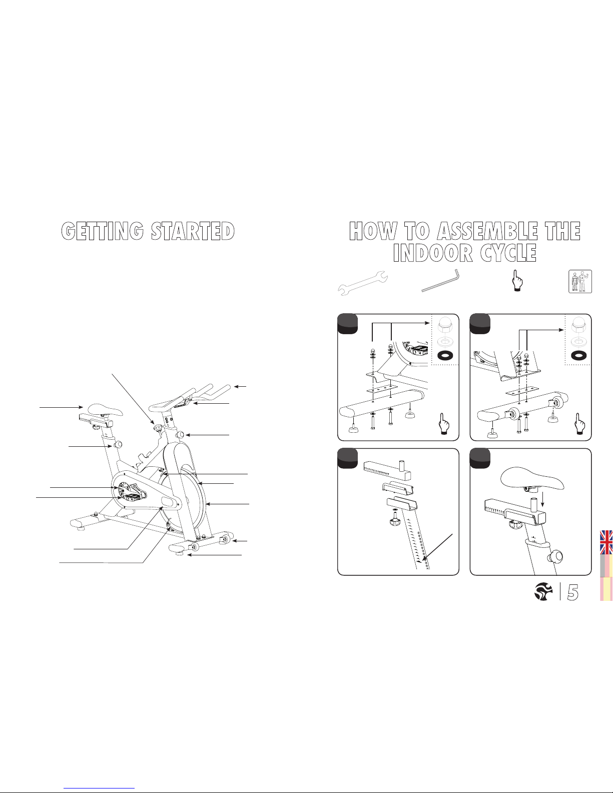
yourself with the parts that are labeled in the drawing below.
YOU WILL FIND THE PRODUCTION CODE ON THE LEFT SIDE OF THE INDOOR CYCLE WITHIN THE LOWER RANGE OF
THE FRAME.
EMERGENCY BRAKE & RESISTANCE KNOB
SADDLE
ADJUSTMENT KNOB
PEDAL
BELT GUARD
MAINTENANCE COVER
HANDLEBAR
ADJUSTMENT KNOB
BRAKE PAD
FLYWHEEL
TRANSPORT
WHEEL
LEVELING FEET
COMPUTER CONSOL
FLYWHEEL LOCK
CADENCE SENSOR
SW 17/19MM
SW 13/15MM
3MM
6MM
HAND
TIGHT
STOP
MARK
1. 2.
4.3.
Page 4
Version 2.0 2010MYR Copyright by Indoorcycling Group GmbH 2012 | www.indoorcycling.com
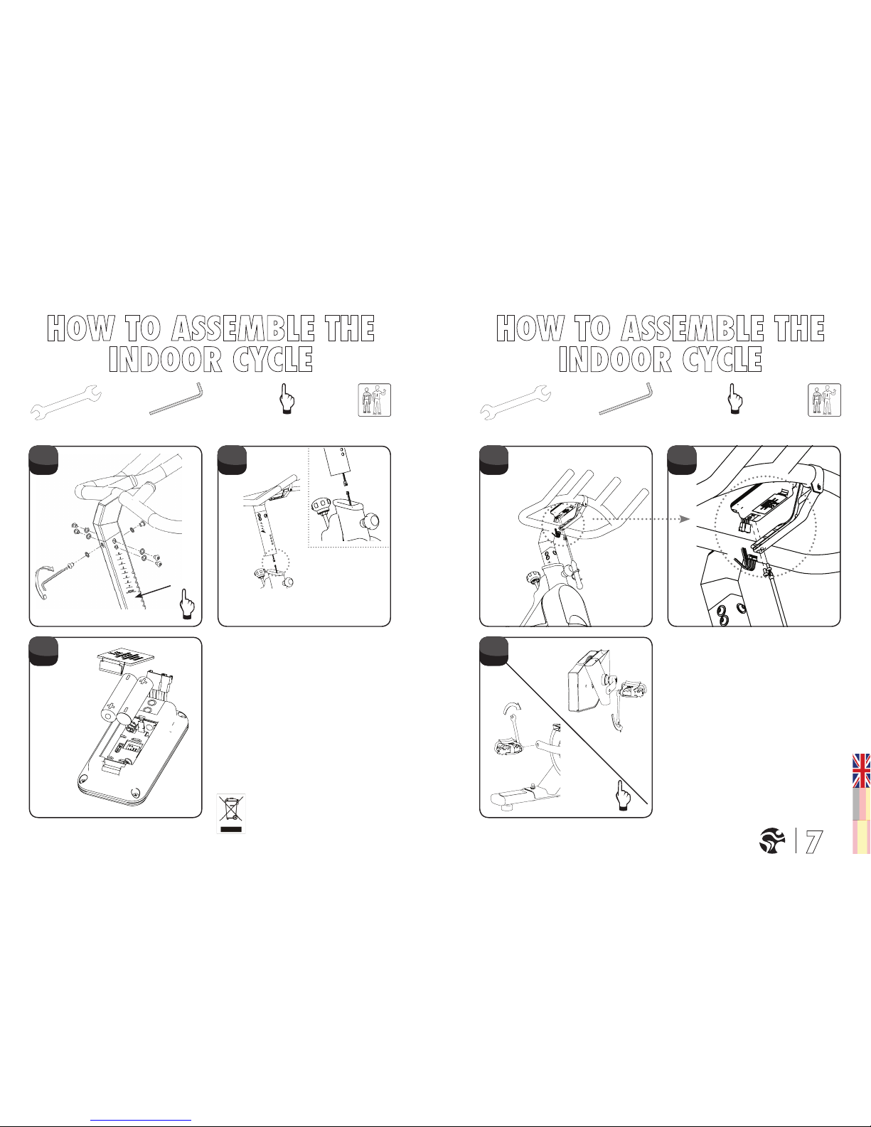
STOP MARK
Marked products or batteries with this symbol may
not be disposed of in normal domestic disposal. For
a professional disposal please consider relevant laws
or defaults for the disposal of elctrical devices and
batteries locally and act accordingly.
2 X LR6 / AA / 1.5V
SW 17/19MM
SW 13/15MM
3MM
6MM
HAND
TIGHT
SW 17/19MM
SW 13/15MM
3MM
6MM
HAND
TIGHT
5. 6. 8.
10.
9.
7.
!! THE BATTERIES MAY NOT:
• Exploited to re
• Get in contact with coins or other metal objects
• Be used in combination with older batteries
• Be used with other makes of dierent types.
.
If you don´t use the equipment for a longer period
of time, please remove the batteries to avoid
any damage by leaking or corroding batteries.
If batteries have discharged, remove all residue
immediately and insert new batteries into the
computer. If you come in contact with residue,
remove this carefully. If possible please use
rechargeable batteries for environmental reasons.
Before scrapping, please take the batteries out of
the computer.
Page 5
Version 2.0 2010MYR Copyright by Indoorcycling Group GmbH 2012 | www.indoorcycling.com
The TOMAHAWK Home Series Indoor Cycle can be adjusted for maximum comfort and exercise
eectiveness. The instructions below describe an approach to adjusting the TOMAHAWK Home
Series Indoor Cycle to ensure optimal user comfort and ideal body positioning; you may choose
to adjust the indoor cycle dierently.
PEDAL STRAP ADJUSTMENT:
Sit on the saddle and position your feet on the pedals, with the bale of your feet directly
above the spindles of the pedals (see the drawing below). Adjust the pedal straps so the
toe clips (cages) are snug but not too tight.
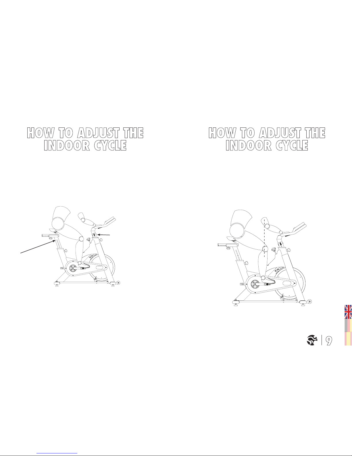
SADDLE HEIGHT ADJUSTMENT:
Sit on the saddle and slowly pedal until the right pedal is in the lowest position. Your
knees should be slightly bent without a dropping of the hips. To avoid hyper extending
your knees, make sure that your legs are not completely straight.
Please do not adjust
saddle height
beyond the stop
mark on the stem.
Please do not adjust
handlebar height beyond the
stop mark on the stem.
SADDLE HORIZONTAL ADJUSTMENT:
Proper horizontal adjustment of the saddle is very important in avoiding injury to the knees. Sit
on the saddle and move the pedals until the crank arms are in horizontal position.
Using your forward most leg as a marker, your kneecap should be directly above the center of
the pedal so that a straight line is created between knee and center of the pedal (see the dotted
line in image below). To adjust the horizontal position of the saddle, loosen the rear adjustment
knob, slidethe saddle forward or backward as required, and then retighten the knob.
Page 6
Version 2.0 2010MYR Copyright by Indoorcycling Group GmbH 2012 | www.indoorcycling.com
If your knees touch the handlebars or if you experience back discomfort while pedalling
for extended periods of time, the height of the handlebars can be adjusted. Turn the front
adjustment knob counter clockwise, slide the handle-bar post up or down, and then retighten
the adjustment knob.
Changing your hand position can change the angle of your back, neck, and arms. To minimize
the stress on your muscles during your workouts, change your hand position frequently.
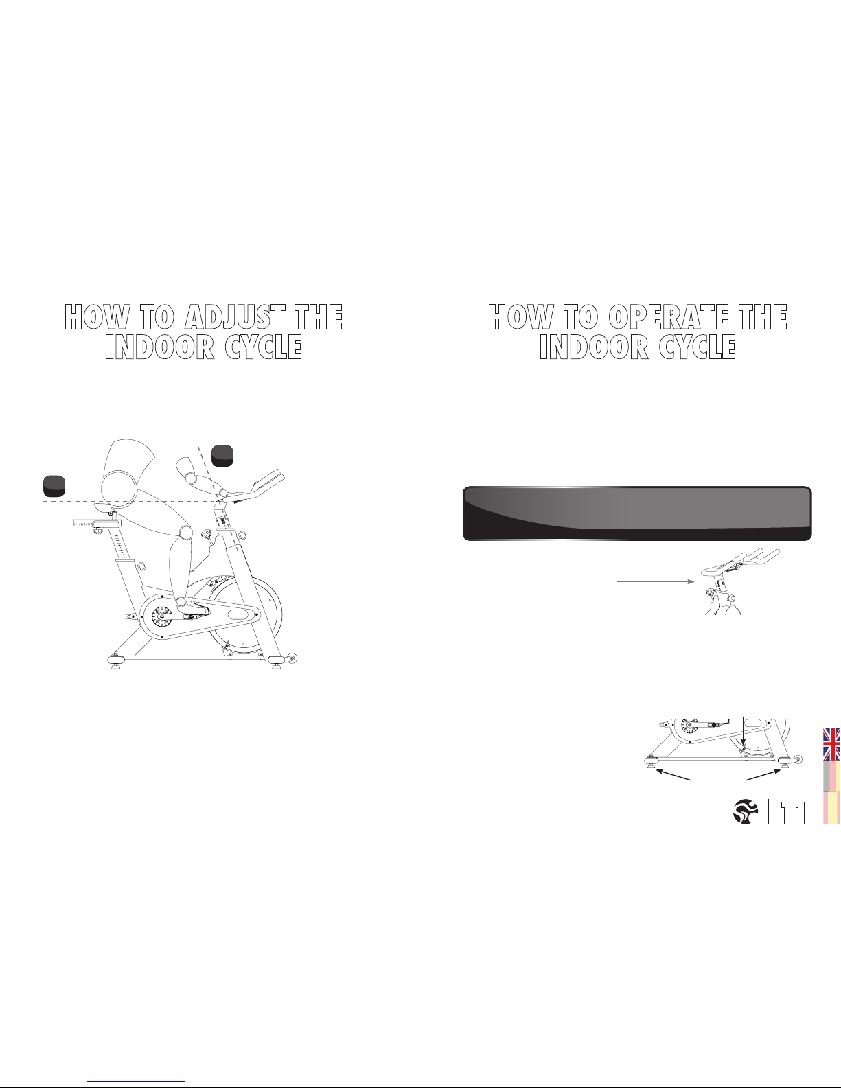
HANDLEBAR ADJUSTMENT:
Begin with the top of the handlebar at relatively the same height or just slightly higher than
the top of the saddle (dotted horizontal line A in the drawing below) and at a neutral fore/aft
position (see dotted vertical line B in drawing below).
RESISTANCE ADJUSTMENT
The preferred level of diculty in pedalling (resistance) can be regulated in ne increments
by use of the resistance knob. To increase the resistance, turn the resistance knob
clockwise. To decrease the resistance, turn the knob counter clockwise.
IMPORTANT: To stop the ywheel (wheel) while pedalling, push down on the red brake
knob. The ywheel should quickly come to a complete stop. Please make sure your shoes
are xed into the toe clip or in case cycling shoes are used your shoe cleat is connected
to the pedal binding while riding. Please apply full resistance load when bike is not in
use to prevent from injuries due to moving drive gear components.
HOW TO MOVE THE INDOOR CYCLE:
Due to the weight of the TOMAHAWK Home Series Indoor Cycle, it is recommended that two
persons move it. While one person lifts the back of the indoor cycle, the second person rmly
holds the handlebar and tips the indoor cycle forward until it rolls on the wheels. Carefullymove the Indoor Cycle to the desired location and then lower it. CAUTION: To reduce the risk of
injury, use extreme caution while moving the TOMAHAWK Home Series Indoor Cycle. Do not
attempt to move it over uneven surfaces and make sure there’s a safety space of 20 inch (minimum) to the nearest equipment is (recommended).
If the indoor cycle rocks on the oor after
being set down, turn the leveling feet
underneath the front or rear stabilizer until
the rocking motion is eliminated. Important:
Please do not unscrew the leveling feet more
then 1⁄2 inch.
RED RESISTANCE KNOB
EMERGENCY BRAKE
LEVELING FEET
FLYWHEEL LOCK
WARNING! The TOMAHAWK Home Series Indoor Cycle does not have a dirct driven ywheel (wheel); the pedals
will continue to move together with the ywheel until the ywheel stops. Reducing speed in a controlled manner is
required. To stop the ywheel immediately, push down the red emergency break knob. Always pedal in a controlled
manner and adjust your desired cadence according to your own abilities.
PUSH THE RED KNOB DOWN = EMERGENCY STOP
A.
B.
Page 7
Version 2.0 2010MYR Copyright by Indoorcycling Group GmbH 2012 | www.indoorcycling.com
WARNING!
REGULAR MAINTENANCE MUST BE PERFORMED ON THE INDOOR CYCLE FOR
OPTIMAL PERFORMANCE AND LONGEVITY.
Please read and follow all instructions below. If the indoor cycle is not maintained as described,
components may wear excessively and the indoor cycle may become damaged. Improper
maintenance will void the warranty terms. If you have questions about maintenance, contact
your local distributor.
NOTE: MANY MAINTENANCE PROCEDURES REQUIRE LUBRICANT SPRAY. MANUFACTURER
RECOMMENDS WD40, BRUNOX OR A SIMILAR SOLVENT AND ACID FREE LUBRICANT.
DAILY MAINTENANCE:
1. Make sure that the indoor cycle is level. If the indoor cycle rocks on your oor, turn the
leveling feet underneath the front or rear stabilizer until the rocking motion is eliminated.
2. After exercising, the indoor cycle should be disinfected and cleaned to maintain a
hygienic environment. First, apply a disinfectant spray to the handlebars and the saddle. Using
a lint-free cloth, dry the handlebars and the saddle. Next, apply a small amount of disinfectant
to a lint-free cloth and clean the adjustment knobs and the adjustment handles. Avoid using
strong detergents on the indoor cycle frame.
WEEKLY MAINTENANCE:
1. Apply a small amount of the lubrication spray to a lint-free cloth, and thoroughly clean the
frame, the handlebar slider and seat sliders the ywheel and the plastic parts of the indoor
cycle.
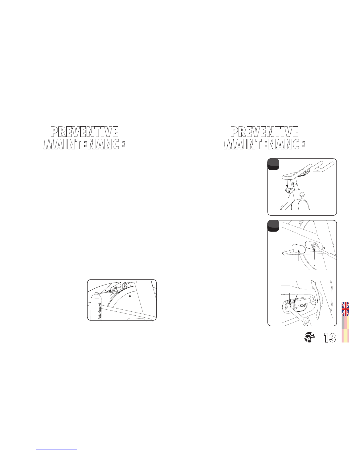
2. For optimal performance of the resistance
system, and to minimize wear on the
brake pad, the solvent free lubricant spray
should be applied to the brake pad using
the lubrication holes on the plastic part
of the brake pad. If fuzz or lint appears on
the brake pad, the brake pad has become
too dry - lubricant spray should be applied
more frequently. Make sure the brake pad
is thoroughly soaked from end to end with
lubricant spray. Then,wipe the excess o.
1. BI-WEEKLY MAINTENANCE:
The indoor cycle should not be used if the
emergency brake system is not working
properly. While sitting on the saddle and
pedalling, test the brake by pushing down
the brake knob. The ywheel should come to
a quick and complete stop.
2. MONTHLY MAINTENANCE:
BELT DRIVEN BIKE
IMPORTANT: A loose belt as well as an over-
tightened belt will cause damage to the belt
and drive system.
CHECKING BELT TENSION:
To check for a loose belt, sit on the saddle,
place your feet on the pedals, move the
pedals until the crank arms are horizontal.
Next, push down the emergency brake
handle and hold it. Then, stand on the pedals
and rock forward and backward. There
should be no more than 1/8th inch (2–3 mm)
of play in the belt. If there is too much play
in the belt, this indicates that the belt is too
loose.
CORRECTING BELT TENSION:
To correct a loose belt: To adjust the belt, pull
o the right and the left maintenance covers
(A).Loosen the axle nut (B) on both ends of
the y-wheel axle two full turns. Loosen the
outer adjustment nut (C) facing the head of
the allen bolt on each side of the ywheel.
Then, turn both (right and left sides) of the
inner adjustment nuts (D) on the inside of
the ywheel bracket 1/4 of a turn at a time
(upward on the R side and downward on L
side) until the belt is properly adjusted. Make
sure to turn both adjustment screws exactly
the same amount to avoid misalignment of
the ywheel.
A
B
C
D
1.
2.
Page 8
Version 2.0 2010MYR Copyright by Indoorcycling Group GmbH 2012 | www.indoorcycling.com
ABOVE GRAPHICS SHOWS THE
RIGHT SIDE OF THE BIKE
(RIDING POSITION)
D
C
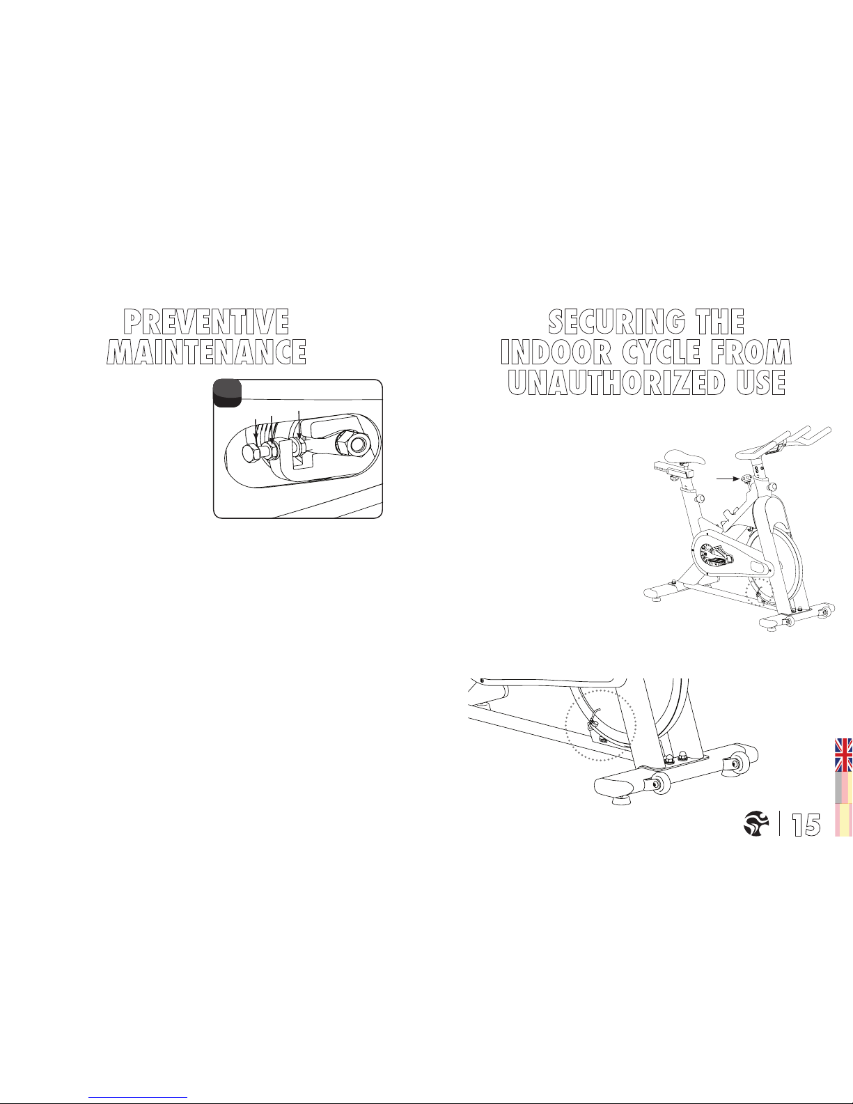
DEAR CUSTOMER,
Align the through hole in the ywheel with
the ywheel protective cover. Turn the
brake knob (A) clockwise until the brake has
completely immobilized the ywheel. Use
the wired cable and key lock provided in
the packaging to then lock the ywheel to
prevent minors from using the product.
A
Re-check the amount of play in the belt as
described at the beginning of this step. If
necessary, readjust the belt.
Finally, retighten the two outer adjustment
nuts (C) and the two axle nuts (B), and
reattach the maintenance covers. To avoid
damage to the ywheel bearings, do not over
tighten the axle nuts (B). Unusual noises or
vibrations are indications that the belt has
been over tightened or that the ywheel is at
a wrong angle.
3.
Page 9
Version 2.0 2010MYR Copyright by Indoorcycling Group GmbH 2012 | www.indoorcycling.com
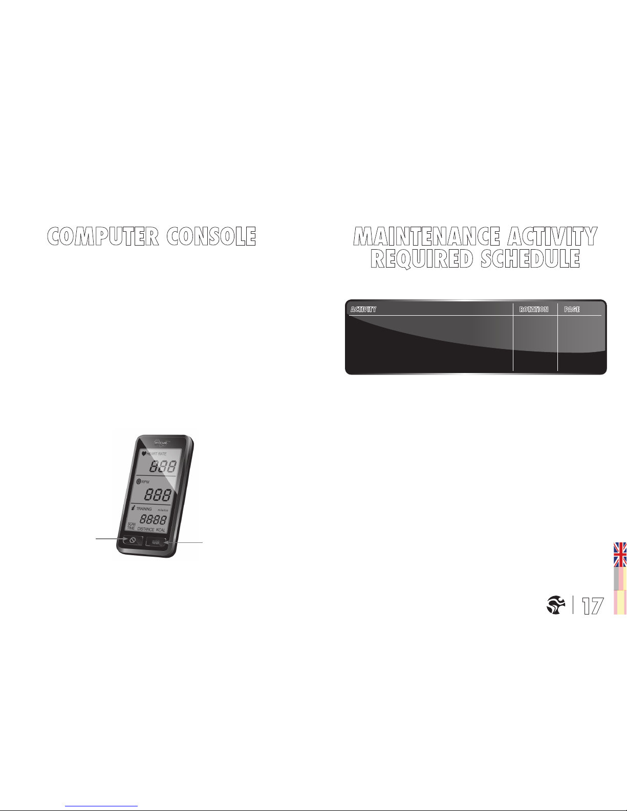
RESET BUTTON
FLOW BUTTON
SPECIFICATIONS:
TECHNICAL FEATURES: • Heart Rate reading only via hand sensors on the handlebar
• Two button easy control
• Premium design
• Special handlebar bracket
• Miles or kilometers reading
TRAINING FEATURES: • Heart Rate reading (actual)
• Cadence / RPM reading (actual)
• Training time
• Distance
• Calorie Consumption (the shown calorie consumption is based
on average values & should only be used for reference purposes)
BUTTON FUNCTION: • Press “reset” button for 5 sec to enter setup mode for miles/km changing
• Press “reset” button for 2-3 sec to reset time, distance and kcal
• Press “ow” button for 1 sec to activate scan function automatically
WARNING!
Heart rate monitoring systems may be inaccurate. Over exercise may result in serious injury or
death. If you feel faint stop exercising immediately
FEET LEVELING, DISINFECTION & CLEANING OF THE BIKE DAILY PAGE 12
SERVICING BRAKE PADS,
DETAILED CLEANING OF THE ENTIRE BIKE WEEKLY PAGE 12
CHECK EMERGENCY BRAKE FUNCTION BI-WEEKLY PAGE 13
CHECK BELT PLAY MONTHLY PAGE 13-14
Page 10
Version 2.0 2010MYR Copyright by Indoorcycling Group GmbH 2012 | www.indoorcycling.com
02 50 A
02 50 06
02 50 04
02 50 03 A
02 50 05
02 40 C S 08
02 40 CrMo R E 08
02 40 90
02 40 BE
02 40 C MD20 08
02 40 CrMO L E 08
02 40 C 2RS
02 40 H L
02 40 02
02 40 08 E 10
02 01 31
02 01 22
02 01 35
02 30 01 MyR
02 40 H
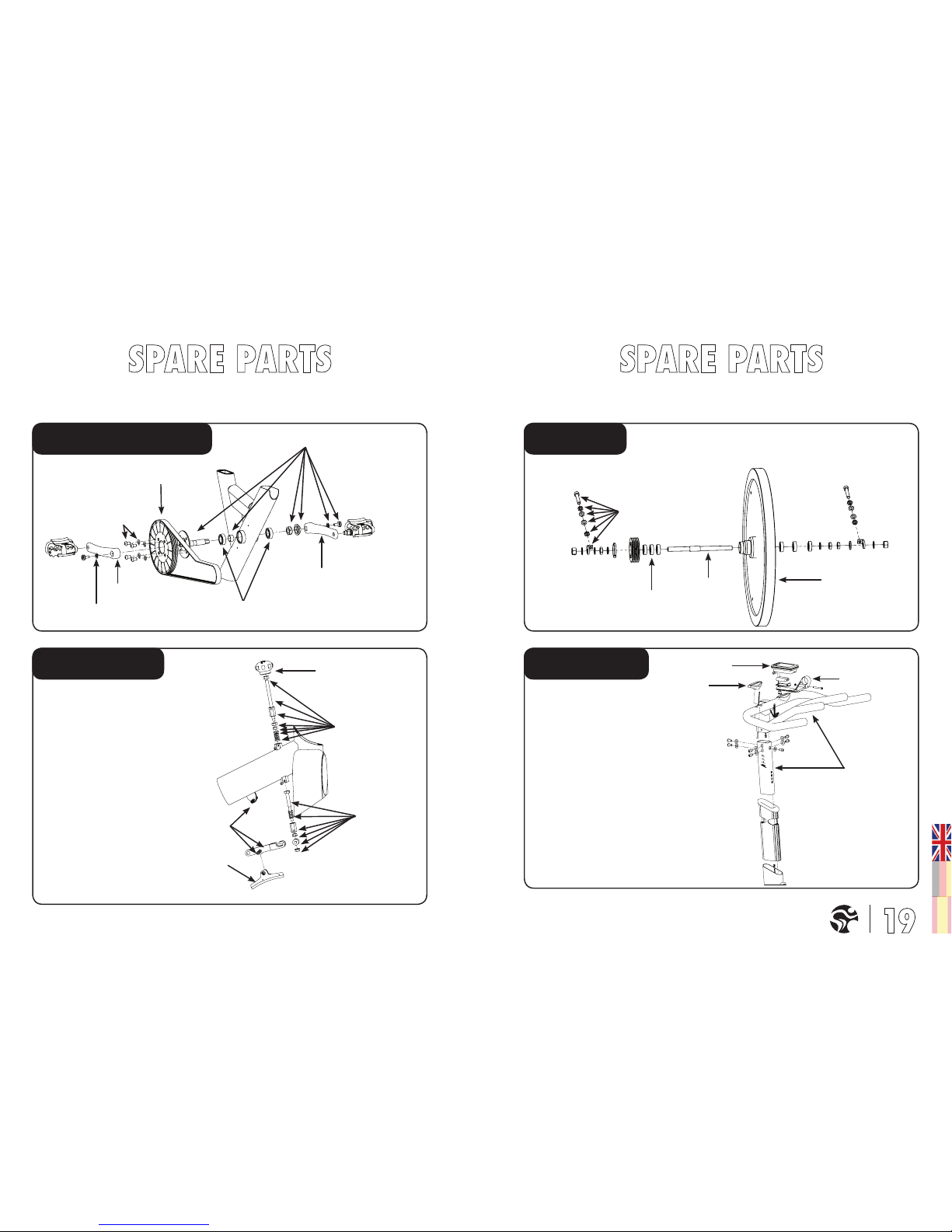
DRIVE GEAR PARTS FLYWHEEL
HANDLEBARBRAKE PARTS
Page 11
Version 2.0 2010MYR Copyright by Indoorcycling Group GmbH 2012 | www.indoorcycling.com
02 42 01 E 08
02 42
03 E 10
02 99 03 MyR
02 42 02 E 10
02 42 04
02 10 A
02 99 02
02 10 B MyR
02 40 08 LK
02 01 33
02 99 50 MYR 10 decal-set complete
02 10 A
01 40 A2
0121VL-3125sw
02 21 AK
02 21 01 MyR
02 20 01 MyR
02 20 02
02 10 D MyR
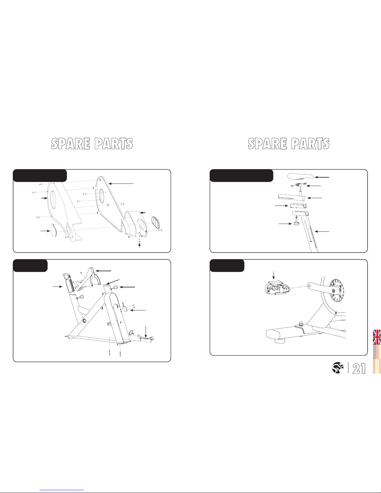
CHAIN GUARD SADDLE SUPPORT
PEDALSFRAME
Page 12
Version 2.0 2010MYR Copyright by Indoorcycling Group GmbH 2012 | www.indoorcycling.com
02 11 05 B MyR
02 11 E
02 11 02 E 08
02 11 06
02 11 01 E 08
02 11 A MyR
02 11 B MyR
Drive Gear Parts
02 40 CrMo R E 08
Right crank
02 40 CrMo L E 08
Left crank
02 40 C S 08 Allen bolt M8x20
02 40 C MD20 08 BB assembly MD
02 40 C 2 RS Ball bearing SKF 6004Z
02 40 90 Chain ring bolt
Brake Parts
02 50 A Brake adjustment knob
02 50 06 Bell crank
02 50 04 Brake pad
02 50 03 A Upper brake rod
02 50 05 Lower brake rod
Flywheel
02 40 H Flywheel axle
02 40 02 Chain tensioner
02 40 H L Flywheel bearing 6001Z
02 40 08 E 10 Flywheel
Chain Guard
02 42 02 E 10 Outer chain guard
02 42 04 Plastic cover
02 42 01 E 08 Inner chain guard
02 42 03 E 10 Left cover
02 99 03 MyR Allen bolt M4x15
Pedals
01 40 A 2 Combi-Pedals
Frame
02 10 A Vertical insert sleeve
02 10 B MyR Pop pin adjustment knob
02 99 02 Bottle holder
02 40 08 LK Flywheel lock
02 01 33 Cadence sensor
02 99 50 MYR 10 Decal-set complete
Belt Drive
02 40 BE Belt PL 1397/550 L
Handlebar
02 30 01 MyR Handle bar
02 01 31 Console
02 01 22 Console bracket
02 01 35 Hand sensors
Saddle Support
0121VL-3125sw Tomahawk Saddle
02 21 AK Saddle mounting bracket
02 21 01 MyR Horizontal saddle support
02 2001 MyR Vertical saddle support
02 20 02 Horizontal insert sleeve
02 10 D MyR Lock handle
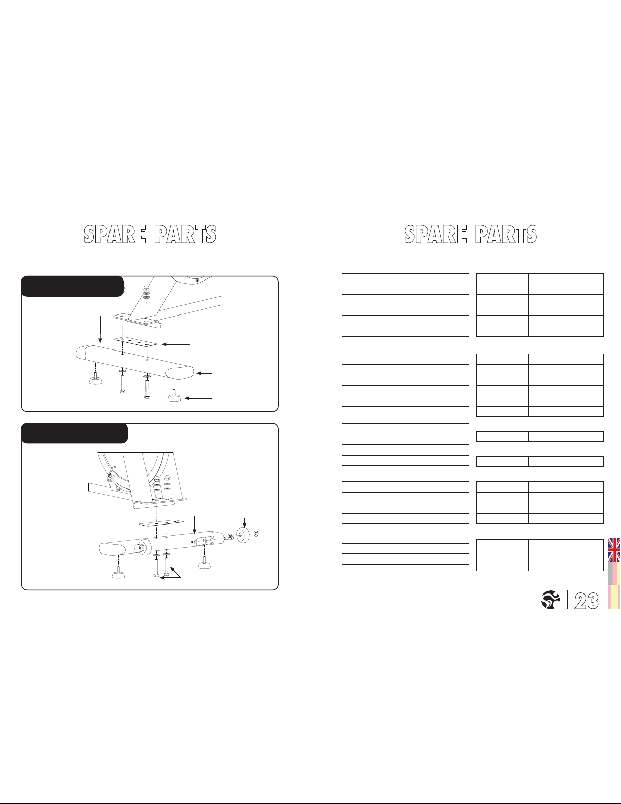
Front Stabilizer
02 11 01 E 08 Front stabilizer
02 11 B MyR Stabilizer mounting kit
02 11 A MyR Transport wheel
Rear Stabilizer
02 11 E PVC gasket
02 11 02 E 08 Rear stabilizer
02 11 06 Plastic end cover
02 11 05 B MyR Rubber foot stand
REAR STABILIZER
FRONT STABILIZER
Page 13
Version 2.0 2010MYR Copyright by Indoorcycling Group GmbH 2012 | www.indoorcycling.com
Indoorcycling Group GmbH warrants that all new equipment will be free of manufacturing
defects in workmanship and materials, becoming eective on the date of original installation.
Parts repaired or replaced under the terms of this warranty will be warranted for the remainder
of the original warranty period only. Warranty may vary by region or country.
TOMAHAWK HOME SERIES INDOOR CYCLE
The TOMAHAWK Home Series Indoor Cycle is not developed for the use in professional
groupclass environments. The use in commercial environment voids the warranty terms. All
wear items are excluded from warranty for example saddle, pedals and pedal straps, brake pad.
2 YEARS WARRANTY: FRAME, HORIZONTAL SADDLE SUPPORT,
DRIVE GEAR PARTS INCL. BELT, BRAKE SYSTEM,
ADJUSTMENT KNOBS, CRANKS, BALL- AND FLYWHEEL
BEARING INCL. AXLES, POWDER COATING, INSERT SLEEVES
FOR HANDLEBAR AND SADDLE POST
Page 14

Version 2.0 2010MYR Copyright by Indoorcycling Group GmbH 2012 | www.indoorcycling.com
Manufactured by: Indoorcycling Group® GmbH
Happurger Str. 86 90482 Nuremberg Germany
WICHTIGER HINWEIS!
BITTE LESEN SIE VOR DER INBETRIEBNAHME DES BIKES DIESES HANDBUCH VOLLSTÄNDIG UND BEFOLGEN SIE ALLE DARIN
BESCHRIEBENEN ANLEITUNGEN ZU MONTAGE, WARTUNG UND BETRIEB DES GERÄTES.
NICHT ORDNUNGSGEMÄSSE HANDHABUNG ODER UNZUREICHENDE WARTUNG FÜHRT ZUM ERLÖSCHEN DER GARANTIE!
CAUTION.
Read all precautions and instructions in this manual
before you begin using this equipment. Please keep this
manual for future reference. Improper assembly, set up,
use or maintenance may void the warranty.
The Myride® content is licensed to be used exclusively
with an exercise bike as a personal training device.
No other license is conveyed, expressed or implied.
EMAIL: INFO@INDOORCYCLING.COM
WEBSITE: WWW.INDOORCYCLING.COM
© 2011 Indoorcycling Group. Myride® Art. no.: 5000 02 (ATSC/NTSC TV) 5000 03 (DVB-T/PAL TV)
Page 15

Version 2.0 2010MYR Copyright by Indoorcycling Group GmbH 2012 | www.indoorcycling.com
TECHNISCHE DATEN:
Das TOMAHAWK Home Serie Bike entspricht nach EN 957 der Benutzerklasse HC und ist für
den ausschließlichen Einsatz im privaten Bereich konzipiert. Es wurde ausschließlich für ein
Unterkörper-, und Herz-Kreislauftraining entwickelt.
WICHTIG!
Dieses Produkt ist nicht für den gewerblichen Gebrauch in Sport- und Fitnesseinrichtungen
konzipiert. Beim gewerblichen Einsatz des Gerätes verfallen sämtliche Garantieansprüche.
P.3
P.4
P.5-7
P.8-10
P.11
P.11
P.12-14
P.15
P.16-17
P.17
P.18-22
P.23
P.24
1. Es liegt in der alleinigen Verantwortung des
Eigentümers, alle Nutzer über die sachgerechte
und ordnungsgemäße Verwendung zu
informieren und erst nach erfolgter Einweisung
durch einen qualizierten Trainer oder
Instruktor die eigenständige Nutzung des Bikes
zu autorisieren ( siehe Seite 8-11 ).
2. Benutzen Sie das Bike erst nach
ordnungsgemäßer Montage und deren
Überprüfung wie auf den Seiten 5-7
beschrieben.
3. Verwenden Sie das Bike nicht im Freien und
setzen Sie es nach Möglichkeit keiner feuchten
und/oder staubigen Umgebung aus. Das Gerät
wurde für die Verwendung in geschlossenen
Räumen konzipiert.
4. Platzieren Sie das Bike immer auf einem
standsicherem, ebenen und zugleich
horizontalem Untergrund. Falls Sie das Bike
auf Teppich- oder Parkettböden platzieren,
empehlt es sich eine Unterlegmatte zu
verwenden, um eventuellen Beschädigungen
des Bodenbelags vorzubeugen.
5. Bitte führen Sie alle in diesem Handbuch
beschriebenen Pege-, Wartungs- und
Servicearbeiten regelmäßig durch. Defekte
Teile sind umgehend zu ersetzen und das Gerät
bis zur erfolgten Instandsetzung nicht mehr
zu benutzen. Verwenden Sie ausschließlich
Ersatzteile des Herstellers.
6. Kindern unter 14 Jahren ist es nicht
erlaubt, das Bike ohne Aufsicht durch einen
dazu qualizierten Instruktor oder Trainer zu
verwenden.
7. Das Bike ist für ein maximales
Benutzergewicht von 130 KG ausgelegt. Das
Bike sollte nicht von Personen benutzt werden,
die dieses max. zulässige Benutzergewicht
überschreiten.
8. Es ist darauf zu achten, nur mit eng
anliegender Rad- oder Sportbekleidung zu
fahren und festes Schuhwerk, vorzugsweise
Radschuhe, zu tragen. Lose Schnürsenkel
können sich im Antriebs-system verfangen und
zu Verletzungen führen. Verstellvorrichtungen
sollten nicht hervorstehen, um die
Bewegungsfreiheit des Nutzers nicht zu
behindern.
9. Das Bike verfügt über keinen Freilauf. Die
Pedale sind über den Antrieb direkt mit dem
Schwungrad verbunden. Die Bewegung kann
nur durch Betätigen der Notbremse oder durch
kontrolliertes Reduzieren der Trittfrequenz
gestoppt werden.
10. Aus Gründen der Benutzersicherheit sollte
niemals komplett ohne Bremswiderstand
gefahrenwerden.
11. Bei Schwindelgefühl oder Übelkeit sollte
das Training sofort unterbrochen werden.
Es empehlt sich einen Arzt zu konsultieren,
falls sich dieses Unwohlsein nicht kurzfristig
bessert.
GEWICHT DES BIKES: 55 KG
MAXIMALES BENUTZERGEWICHT: 130 KG
BENUTZERGRÖSSE: GEEIGNET FÜR KÖRPERGRÖSSEN VON 150 – 205 CM
BENÖTIGTE STANDFLÄCHE: 55 X 115 CM
MAX. SATTEL UND LENKERHÖHE: CA. 110 CM
WARNUNG!
Um einem Sicherheitsrisiko durch unsachgemäße
Handhabung des Gerätes vorzubeugen ist es
erforderlich, die nachfolgenden Sicherheitshinweise
und Informationen vor der Inbetriebnahme des
Gerätes im Detail zu lesen und zu beachten!
WICHTIGER HINWEIS:
Falls Sie gesundheitliche Probleme haben oder
vorbelastet sind, empfiehlt es sich einen Arzt zu
konsultieren, um die für Sie am besten geeignete
Trainingsmethode zu finden. Zu hohe Trai-
ningsbelastung oder Intensität sowie die unsachgemäße
Nutzung des Bikes kann zu gesund- heitlichen Schäden
und ernsthaften Verletzungen führen.
Der Hersteller übernimmt ausdrücklich keine Verantwortung für
gesundheitliche Risiken, Schäden oder Folgeschäden die durch die
Benutzung dieses Gerätes entstehen können insofern es sich hierbei
nicht um Folgeerschei- nungen handelt, die auf Material und /oder
Herstellungsmängel zurückzuführen sind und in der Verantwortung
des Herstellers liegen.
Page 16

Version 2.0 2010MYR Copyright by Indoorcycling Group GmbH 2012 | www.indoorcycling.com
SEHR GEEHRTER KUNDE,
Wir möchten uns zuerst für Ihr Vertrauen und Ihre Kaufentscheidung bedanken. Mit dem
Tomahawk Indoor Cycle haben Sie sich für ein Qualitätsprodukt entschieden, das nach
den neuesten technischen Erkenntnissen entwickelt und somit auf höchste Beanspruchung
und Zuverlässigkeit ausgelegt wurde.
Dieses Höchstmaß an Zuverlässigkeit lässt sich jedoch nur über eine regelmäßige Pege
und Wartung sicherstellen. Bei entsprechender Einhaltung der in diesem Handbuch
beschriebenen Maßnahmen wird eine maximale Standfestigkeit und Lebensdauer bei
minimalem Wartungsaufwand an den Tag gelegt und garantiert Ihnen einen langjährigen,
störungsfreien Betrieb.
DEN PRODUKTIONSCODE FINDEN SIE AUF DER LINKEN SEITE DES INDOOR CYCLES IM UNTEREN BEREICH DES RAHMENS.
SW 17/19MM
SW 13/15MM
3MM
6MM
HANDFEST
ANZIEHEN
STOP
MARKIERUNG
1. 2.
4.3.
NOTBREMS- UND BREMSARRETIERGRIFF
SATTEL
ARRETIERGRIFF
PEDAL
KETTENKASTEN
ABDECKKAPPE
LENKER
ARRETIERGRIFF
BREMSBELAG
SCHWUNGSCHEIBE
TRANSPOR-
TROLLE
STANDFUSS
COMPUTER KONSOLE
SCHWUNGSCHEIBENSICHERUNG
SENDEEINHEIT
handfest
anziehen
Page 17

Version 2.0 2010MYR Copyright by Indoorcycling Group GmbH 2012 | www.indoorcycling.com
!! DIE BATTERIEN DÜRFEN NICHT:
• mit Feuer in Berührung kommen
• mit Münzen oder anderen metallischen Gegen-ständen
in Berührung kommen
• zusammen mit alten Batterien verwendet werden
• verschiedenartig sein.
Sollten Sie das Gerät einen längeren Zeitraum nicht
verwenden, entfernen Sie die Batterien um Schaden
durch Auslaufen oder Korrosion zu ver-meiden.
Sollten die Batterien auslaufen, entfernen Sie sofort
alle Rückstände und setzen Sie neue Batterien in den
Computer ein. Bei Kontakt mit den Rückständen,
entfernen Sie diese sorgfältig. Verwenden Sie nach
Möglichkeit wiederauadbare Batterien. Entfernen
Sie die Batterien aus dem Computer bevor Sie diesen
entsorgen.
Mit diesem Symbol gekennzeichneten
Produkte oder Batterien dürfen nicht im
normalen Haushaltsabfall entsorgt werden.
Für eine fachgerechte Entsorgung infor-mieren Sie sich bitte über
maßgebliche Gesetze oder Vorgaben zur Entsorgung von elektrischen Geräten und Batterien vor Ort und handeln entsprechend.
2 X LR6 / AA / 1.5V
SW 17/19MM
SW 13/15MM
3MM
6MM
SW 17/19MM
SW 13/15MM
3MM
6MM
5. 6. 8.
10.
9.
7.
HANDFEST
ANZIEHEN
HANDFEST
ANZIEHEN
STOP
MARKIERUNG
Bei Betrieb des Radcomputers mit
wiederauadbaren Batterien ist darauf zu
achten das die Batterien ein Spannung von
1,5V nicht unterschreiten, da es ansonsten
zu Funktionsstörungen beim Betrieb des
Gerätes kommen kann.
Page 18

Version 2.0 2010MYR Copyright by Indoorcycling Group GmbH 2012 | www.indoorcycling.com
HORIZONTALE SATTELEINSTELLUNG:
Die horizontale Positionierung des Sattels ist sehr wichtig, um Verletzungen an den
Kniegelenken vorzubeugen. Setzen Sie sich auf den Sattel und bringen Sie die Kurbelarme
in die horizontale Position.
Das Kniegelenk am nach vorne gerichteten Bein sollte sich direkt über der Achse des Pedals
benden. Falls dies nicht der Einstellung Ihres Bikes entspricht, justieren Sie bitte die
horizontale Sattelverstellung nach vorne oder hinten um diese Sitzposition zu erreichen.
Vertikale Sattelverstellung nicht
über die STOP-Markierung
hinaus in der Höhe verstellen.
Vertikale Lenkerverstellung nicht über die STOP-
Markierung hinaus in der Höhe verstellen.
Das Tomahawk Home Serie Bike kann sehr variabel, entsprechend den Bedürfnissen
verschiedener Benutzergruppen eingestellt werden um einen optimalen Fahrkomfort
unter Berücksichtigung einer für diesen Zweck idealen Körperhaltung zu gewährleisten
und um optimale Trainingsergebnisse erzielen zu können. Die nachfolgend beschriebenen
Möglichkeiten zeigen nur einige der meist verwendeten Einstellvarianten des Bikes. Es obliegt
dem Benutzer, eine für ihn ideale Fahrposition einzustellen.
SITZHÖHENEINSTELLUNG:
Setzen Sie sich auf den Sattel und stellen Sie sicher, dass Ihr Becken nicht nach einer Seite
gekippt ist, wenn das Pedal die im Bild gezeigte Stellung eingenommen hat. Platzieren Sie
Ihre Schuhe in den Schuhkörben der Pedale oder bei Verwendung von Radschuhen im
Bindungssystem, falls Ihr Bike mit einem Kombi-Pedalsystem ausgerüstet ist.
WICHTIG !
Fangen Sie an langsam zu treten, bis das Pedal die im Bild gezeigt Position erreicht hat. Die
vertikale Sattelstütze sollte jetzt so eingestellt sein, dass die Knie immer beim Errei-chen dieser
Pedalstellung leicht angewinkelt sind, ohne dass das Becken nach einer Seite kippt. Als Faustregel
gilt, dass sich die Sattelhöhe in etwa zwei Finger breit unter halb des Beckenknochens bendet.
Bitte vermeiden Sie es, mit durchgestreckten Knien oder kippendem Becken zu fahren.
Fixieren der Stützverstellung:
Einrasten des Einstellknopfes und
im Uhrzeigersinn festdrehen
Höhenverstellung
der Stütze:
Ziehen des Einstellknopfes,
selbstständiges
Einrasten (hörbar)
Lösen der Stützverstellung:
Einstellknopf gegen
Uhrzeigersinn drehen
Verstellknopf zur
horizontalen Verstellung
des Sattels
Page 19

Version 2.0 2010MYR Copyright by Indoorcycling Group GmbH 2012 | www.indoorcycling.com
Als Nächstes sollte die Position des Lenkers möglichst genau auf Ihre Körpergröße eingestellt werden. Hierzu winkeln Sie bitte Ihren Arm an und berühren mit dem Ellenbogen das vordere Ende des Sattels. Bei ausgestrecktem Unterarm sollte nun die Spitze
Ihres Mittelngers den Mittelpunkt des Lenkers berühren. Eine für ungeübte Fahrer
ideale und schonende Sitzposition ist erreicht, wenn Ihr Rücken eine Neigung in einem
Winkel von 45° eingenommen hat.
Der Lenker oeriert vielfältige Handpositionen und Einstellmöglichkeiten, die es dem geübten Fahrer leicht machen,
seine ideale Sitz- und Handpositionierung zu nden. Es wird empfohlen während längerer Trainingseinheiten die
Handposition regelmäßig zu wechseln, um einseitige und monotone Belastungen der Muskeln, Bänder und Gelenke zu
vermeiden.
LENKERPOSITIONIERUNG:
Zu Beginn der Einstellung sollte bei ungeübten Benutzern der Lenker in gleicher Höhe mit dem
Sattel eingestellt sein (Linie A) und sich auf der „0“ Markierung (Linie B) benden. Wenn die Knie
beim stehenden Fahren den Lenker berühren oder diese Sitzposition bei längerem Fahren unbequem ist, sollte zunächst der Lenker etwas höher eingestellt werden. Zur Lenker in der Vertikalen
niemals über die STOP-Markierung hinaus in der Höhe verstellen. Zur Betätigung des Einstell-
EINSTELLUNG DES WIDERSTANDES:
Der individuell angestrebte Widerstand kann mit Hilfe des Widerstandsreglers in sehr feinen
Stufen eingestellt werden. Um den Widerstand zu erhöhen, wird der Widerstands- regler im
Uhrzeigersinn, um den Widerstand zu verringern gegen den Uhrzeigersinn gedreht.
Um die Schwungscheibe während des Betriebs zu stoppen muss der Notbremsknopf nach unten gedrückt werden.
Während des Trainings ist darauf zu achten, dass die Schuhe in den dafür vorgesehenen Fußkörben platziert oder
bei Verwendung von Radschuhen mit dem Bindungssystem verbunden sind. Bitte stellen Sie sicher, dass die
Bremse während der Nichtbenutzung des Bikes auf maximalen Widerstand eingestellt ist,um ein Bewegen der
Antriebskomponenten zu verhindern.
AUFSTELLEN DES INDOOR CYCLES:
Es empehlt sich, das Indoor Cycle mit zwei Personen zu bewegen. Um Unfällen vorzubeugen und Beschädigungen an den Einschubbuchsen des Lenkers zu vermeiden
ist es notwendig, dass die vertikale Lenkerverstellung fest xiert wurde bevor Sie das Rad
kippen. Bitte seien Sie besonders vorsichtig wenn Sie das Indoor Cycle über einen
unebenen Boden bewegen. Hier empehlt sich eine 2. Person, die das eventuelle Kippen
zur Seite verhindert. Weiterhin ist darauf zu achten einen Sicherheitsabstand von
mindestens 50 cm zu anderen Geräten einzuhalten.
Überprüfen Sie die Standsicherheit des Indoor Cycles am
Einsatzort und justieren Sie ggf. die niveauregulierbaren
Stellfüße auf der Unterseite der Stabilisatoren, um die
gewünschte Stand- sicherheit zu gewährleisten. Wichtig:
Die Standfüße sollen immer möglichst weit hinein
gedreht werden, nicht mehr als ca. 1cm herausdrehen!
STANDFÜSSE
SCHWUNGSCHEIBENSICHERUNG
Das Indoor Bike verfügt über keinen Freilauf. Die Schwungscheibe ist fest mit den Pedalen verbunden und stoppt nicht
selbstständig, wenn der Benutzer die Tretbewegung unterbricht. Bitte kontrollieren Sie immer Ihre Bewegungen und
verlangsamen Sie diese kontrolliert um anzuhalten oder drücken Sie den roten Notbremsgriff einfach nach unten um die
Bewegung schnell zu verlangsamen damit die Schwungscheibe zum Stehen kommt, um das Training zu unterbrechen.
NOTBREMSE = BREMSGRIFF NACH UNTEN DRÜCKEN.
A.
B.
Verstellknopf zur
Höhenverstellung
des Lenkers. Zur
Handhabung des
Knopfes lesen Sie
bitte unbedingt
Seite 8 !
ROTER WIDERSTANDSREGLER (DREHEN)
ROTER NOTBREMSKNOPF (DRÜCKEN)
Aus Sicherheitsgründen ist darauf zu achten immer unter kontrollierter Bewe-
gung zu fahren und die Tretfrequenz dem fahrerischen Fähigkeiten anzupassen.
Page 20

Version 2.0 2010MYR Copyright by Indoorcycling Group GmbH 2012 | www.indoorcycling.com
WARNUNG!
Die nachfolgenden Wartungs- und Pegemaßnahmen müssen in der beschriebenen Regel-
mäßigkeit durchgeführt werden, um ein Höchstmaß an Betriebssicherheit und Lebensdauer
zu gewährleisten. Bitte befolgen Sie die nachfolgenden Anweisungen gewissenhaft. Nicht
regelmäßig durchgeführte Wartungs- und Pegearbeiten führen zu erhöhtem Verschleiß am
Produkt und zum Erlöschen der Garantieleistungen. Falls Sie weitere Fragen zu diesem Thema
haben, wenden Sie sich bitte an unseren technischen Support.
Bitte verwenden Sie ausschließlich die von uns empfohlenen säure- und lösungsmittelfreien
Wartungs- und Pegemittel, um Beschädigungen an den Komponenten des TOMAHAWK
Home Serie Bikes vorzubeugen.
TÄGLICHE MASSNAHMEN:
1. Prüfen des Indoor Cycles auf Standsicherheit.
2. Das Indoor Cycle muss aus hygienischen Gründen nach jeder Benutzung gereinigt werden.
Sorgen Sie auch dafür, dass ausreichend weiche Lappen oder Zellstotücher sowie Wartungs- und Desinfektionsmittel bereit stehen. Desinzieren Sie zuerst den Sattel und Lenker
mit einem dafür geeigneten Mittel und reinigen Sie danach das gesamte Indoor Cycle von
Körperschweißrückständen.
WÖCHENTLICHE MASSNAHMEN:
1. Je nach Nutzung des Gerätes ist es erforderlich, mindestens einmal pro Woche eine
detaillierte Reinigung des Indoor Cycles durchzuführen. Hierzu sprühen Sie bitte
Wartungsspray auf einen weichen Lappen und reinigen Sie alle Plastikteile, die komplette
Schwungscheibe und den kompletten Rahmen.
2. Um eine optimale Funktion des Bremssystems aufrecht zu erhalten und den
Verschleiß der Bremsbeläge zu minimieren,
muss der Bremsbe-lag mit Wartungsspray behandelt werden. Hierzu sprühen Sie bitte das
Wartungsspray in die dafür vorgesehenen
Löcher bis sich der Bremsbelag vollgesogen
hat. Fusselige Bremsbeläge oder ungleichmäßiger Widerstand sind eindeutige Zeichen für
zu trockene Bremsbeläge.
14-TÄGIGE MASSNAHMEN:
1. Aus Gründen der Betriebssicherheit muss
die Notbremse auf ihre Funktion überprüft
werden. Hierzu drücken Sie während des
Fahrens den roten Notbremsknopf nach
unten. Bei optimaler Funktion sollte es zu
einer sofortigen Brems-wirkung bis hin zum
vollständigen Stillstand der Schwungscheibe
kommen.
2. MONATLICHE MASSNAHMEN:
RIEMENSPANNUNG ÜBERPRÜFEN UND
EINSTELLEN
Bringen Sie die Pedalarme in eine
waagerechte Position. Betätigen Sie das
Notbremssystem und wippen Sie (stehend
auf den Pedalen) vor und zurück. Rutscht
der Riemen durch, ist es notwendig diesen
zu spannen. Achtung! Zu große Riemen
spannung führt zu erhöhten Laufgeräuschen
und Verschleiß am Antriebssystem. Zuerst
entfernen Sie die ovalen Abdeckkappen (A)
auf beiden Seiten des Schwungrads. Danach
lockern Sie die beiden Achsmuttern 17mm
(B) um ca. 2 Umdrehungen.
Als Nächstes lösen Sie die Sicherungsmuttern (C) auf
beiden Seiten der Achsaufnahme.
Zum optimalen Einstellen der Riemenspannung ist darauf
zu achten, dass Sie die beiden Justier-muttern (D) absolut
gleichmäßig lösen (Spannung lockert sich) oder festziehen
(Spannung erhöht sich). Meist genügt schon ein ¼ bis ½
Umdrehung um den gewünschten Effekt zu erzielen.
Ungleichmäßiges Drehen der Justiermuttern führt
zu Fehlausrichtung der Antriebslinie und macht sich
durch erhöhte Geräusche, unrunden Lauf underhöhten
Verschleiß bemerkbar. Nach dem Einstellen die
Sicherungsmuttern (C) fixieren, die Achsmuttern (B) wieder
festziehen und Abdeck-kappen (A) anbringen.
A
B
C
D
1.
2.
Page 21

Version 2.0 2010MYR Copyright by Indoorcycling Group GmbH 2012 | www.indoorcycling.com
ANSICHT IN DEN GRAFIKEN
FAHRTRICHTUNG RECHTE SEITE
D
C
SEHR GEEHRTER KUNDE,
Richten Sie die Durchgangsönung in
der Schwungscheibe an der Önung der
Sicherheitsabdeckung aus. Drehen Sie den
Bremsgri (A) so lange im Uhrzeigersinn bis
sich die Schwungscheibe nicht mehr drehen
lässt. Verwenden Sie das im Verpackungsumfang enthaltene Kabel und Bügelschloss
um die Schwungscheibe gegen unbefugten
Zugri zu sichern.
A
Der Riemenantrieb darf aus Sicherheitsgründen unter normalen Nutzungsbedingungen
nicht durch-rutschen. Falls dies der Fall sein
sollte, verfahren Sie wie oben beschrieben,
um die Spannung entsprechend zu erhöhen.
Achtung! Zu hohe Riemenspannung führt zu
erhöhtem Verschleiß an den Lagerungen des
Antriebs und am Riemen.
3.
Page 22

Version 2.0 2010MYR Copyright by Indoorcycling Group GmbH 2012 | www.indoorcycling.com
SPEZIFIKATIONEN:
TECHNISCHE FUNKTIONEN: • Herzfrequenzmessung nur mittels Handsensoren
• Einfache Bedienung über 2 Tasten
• Premium Produkt Design
• Spezielle Lenkerhalterung
• Km oder Meilen Anzeige
TRAININGSFUNKTIONEN: • Aktuelle Herzfrequenz
• Trittfrequenz / RPM aktuell
• Trainingszeit
• Entfernung
• Kalorienverbrauch (der angezeigte Kalorienver-brauch basiert
auf Durchschnittswerten und dient als Referenz)
BEDIENUNG: • Drücken Sie die Reset-Taste für 5 Sek. um in den
Einstellungsmodus für Meilen/km Anzeige zu gelangen
• Drücken Sie die Reset-Taste für 2-3 Sek. um Zeit, Entfernung
und Kalorienverbrauch zurück zu setzen
• Drücken Sie die Flow-Taste für 1 Sek. um die An-zeigefunktion
automatisch für Zeit, Entfernung und Kalorienverbrauch zu aktivieren
REINIGUNG UND DESINFEKTION SOWIE
STANDSICHERHEIT DES BIKES PRÜFEN TÄGLICH SEITE 12
WARTUNG DER BREMSBELÄGE UND
DETAILREINIGUNG DES GESAMTEN BIKES WÖCHENTLICH SEITE 12
NOTBREMSFUNKTION TESTEN 14-TÄGIG SEITE 13
ÜBERPRÜFUNG DER RIEMENSPANNUNG MONATLICH SEITE 13-14
SUN-TASTE FLOW-TASTE
AKTUELLE
HERZFREQUENZ
DURCHSCHNITTLICHE
HERZFREQUENZ
DURCHSCHNITTLICHE
TRITTFREQUENZ
AKTUELLE TRITTFREQUENZ
TRAININGSINFORMATIONEN
TRAININGSZEIT
MILES/KM
SCANFUNKTION: WECHSEL DER
TRAININGSINFORMATIONEN
ZEIT, ENTFERNUNG UND
KALORIENVERBRAUCH
ENTFERNUNG
KALORIENVERBRAUCH
Checkliste und Zeitplanung für Pege- und Wartungsmaßnahmen
WARNUNG!
Systeme der Herzfrequenzüberwachung können ungenau sein. Übermäßiges Trainieren
kann zu ernsthaftem gesundheitlichem Schaden oder zum Tod führen. Bei Schwindel-/
Schwächegefühl sofort das Training beenden!
Dieses ‚Gerät ist nicht dafür bestimmt, durch Personen (einschließlich Kinder) mit
eingeschränkten physischen, sensorischen oder geistigen Fähigkeiten oder mangels Erfahrung
und/oder mangels Wissen benutzt zu werden. Es sei denn, sie werden durch eine für Ihre
Sicherheit zuständige Person beaufsichtigt oder erhielten von Ihr Anweisungen, wie das Gerät
zu benutzten ist.
Kinder müssen beaufsichtigt werden, um sicherzustellen, dass sie nicht mit dem Gerät spielen.
Page 23

Version 2.0 2010MYR Copyright by Indoorcycling Group GmbH 2012 | www.indoorcycling.com
02 50 A
02 50 06
02 50 04
02 50 03 A
02 50 05
02 40 C S 08
02 40 CrMo R E 08
02 40 90
02 40 BE
02 40 C MD20 08
02 40 CrMO L E 08
02 40 C 2RS
02 40 H L
02 40 02
02 40 08 E 10
02 01 31
02 01 22
02 01 35
02 30 01 MyR
02 40 H
ANTRIEBSTEILE SCHWUNGSCHEIBE
LENKERBREMSSYSTEM
Page 24

Version 2.0 2010MYR Copyright by Indoorcycling Group GmbH 2012 | www.indoorcycling.com
02 42 01 E 08
02 42
03 E 10
02 99 03 MyR
02 42 02 E 10
02 42 04
02 10 A
02 99 02
02 10 B MyR
02 40 08 LK
02 01 33
02 99 50 MYR 10 Aufkleber-Set komplett
02 10 A
01 40 A2
0121VL-3125sw
02 21 AK
02 21 01 MyR
02 20 01 MyR
02 20 02
02 10 D MyR
KETTENKASTEN SATTELAUFNAHME
PEDALERAHMEN
Page 25

Version 2.0 2010MYR Copyright by Indoorcycling Group GmbH 2012 | www.indoorcycling.com
02 11 05 B MyR
02 11 E
02 11 02 E 08
02 11 06
02 11 01 E 08
02 11 A MyR
02 11 B MyR
HINTERER STABILISATOR
VORDERER STABILISATOR
ANTRIEBSTEILE
02 40 CrMo R E 08
Kurbel rechts
02 40 CrMo L E 08
Kurbel links
02 40 C S 08 Inbusschraube M8x20
02 40 C MD20 08 MD20 Tretlagerachse
02 40 C 2 RS Kugellager SKF 6004Z
02 40 90 Befestigungsschrauben
BREMSSYSTEM
02 50 A Bremsarretiergriff
02 50 06 Bremsumlenkhebel
02 50 04 Bremsbelag
02 50 03 A Oberes Bremssystem
02 50 05 Unteres Bremssystem
SCHWUNGSCHEIBE
02 40 H Schwungscheibenachse
02 40 02 Kettenspanner
02 40 H L Kugellager 6001Z
02 40 08 E 10 Schwungscheibe
KETTENKASTEN
02 42 02 E 10 Vorderer Kettenkasten
02 42 04 Gummiabdeckung
02 42 01 E 08 Hinterer Kettenkasten
02 42 03 E 10 Linke Abdeckung
02 99 03 MyR Inbusschraube M4x15
PEDALE
01 40 A 2 Kombipedale
RAHMEN
02 10 A Vertikale Einschubbuchse
02 10 B MyR Spann- und Arretiergriff
02 99 02 Flaschenhalter
02 40 08 LK
Schwungscheibensicherung
02 01 33 Sendeeinheit
02 99 50 MYR 10 Aufkleber-Set komplett
RIEMENANTRIEB
02 40 BE Riemen PL 1397/550 L
LENKER
02 30 01 MyR Lenker
02 01 31 Konsole
02 01 22 Halter für Konsole
02 01 35 Handsensoren
SATTELAUFNAHME
0121VL-3125sw Tomahawk Sattel
02 21 AK Sattelkloben
02 21 01 MyR Horizontale Sattelstütze
02 2001 MyR Vertikale Sattelstütze
02 20 02 Horizont. Einschubbuchse
02 10 D MyR Klemmgriff
VORDERER STABILISATOR
02 11 01 E 08 Vorderer Stabilisator
02 11 B MyR Stabilisatorbefestigung
02 11 A MyR Transportrolle
HINTERER STABILISATOR
02 11 E PVC Dichtung
02 11 02 E 08 Hinterer Stabilisator
02 11 06 Plastikabdeckung
02 11 05 B MyR Standfuß
Page 26

Version 2.0 2010MYR Copyright by Indoorcycling Group GmbH 2012 | www.indoorcycling.com
Die Indoorcycling Group GmbH garantiert, dass alle neuen Produkte am Tag der
Lieferung zum Kunden frei von Fertigungs- und Materialfehlern sind. Nachfolgend sind die
unterschiedlichen Garantiezeiten für die an den TOMAHAWK Home Serie Bikes verwendeten
Komponenten und Baugruppen aufgelistet. Detaillierte Informationen zu unseren
Garantie- und Geschäftsbedingungen nden Sie im Internet unter www.indoorcycling.com.
TOMAHAWK HOME SERIE INDOOR BIKE
Das Bike wurde nicht für den professionellen Einsatz in gewerblichen Fitnessanlagen
konzipiert. Bei einer Verwendung des Gerätes im gewerblichen Umfeld erlischt jeglicher
Garantieanspruch. Weiterhin sind alle Verschleißteile wie z.B. Sattel, Pedale und Pedalriemen sowie Bremsbeläge von der Garantie ausgenommen.
2 JAHRE GARANTIE: RAHMENKONSTRUKTION, SCHWEISSNÄHTE,
HORIZONTALE SATTELVER-STELLUNG, ANTRIEBSEINHEIT
INKLUSIVE RIEMEN, BREMSSYSTEM, ARRETIERGRIFFE,
TRETKURBELN, TRET- UND SCHWUNGRADLAGER INKLUSIVE
ACHSEN, PULVERBESCHICHTUNG, EINSCHUBBUCHSEN
Page 27

Version 2.0 2010MYR Copyright by Indoorcycling Group GmbH 2012 | www.indoorcycling.com
NOTA IMPORTANTE:
LEA TODAS LAS INSTRUCCIONES Y PRECAUCIONES EN ESTE MANUAL ANTES DE LA PUESTA EN SERVICIO DE LA BICICLETA Y
OBSERVE TODAS LAS INSTRUCCIONES DESCRITAS PARA MONTAJE, MANTENIMIENTO Y FUNCIONAMIENTO DEL EQUIPO.
¡EL USO Y MANEJO INAPROPIADO, MONTAJE INCORRECTO Y LA FALTA DE MANTENIMIENTO PUEDE CAUSAR EN
CANCELACIÓN DE LA GARANTÍA!
Manufactured by: Indoorcycling Group® GmbH
Happurger Str. 86 90482 Nuremberg Germany
ACHTUNG.
Machen Sie sich mit allen Sicherheitsmaßnahmen
und -anweisungen, die in dieser Bedienungsanleitung
beschrieben sind, vertraut, bevor Sie das Gerät in Betrieb
nehmen. Bewahren Sie diese Anleitung sorgfältig auf.
Bei unsachgemäßem Zusammen- und Aufbau,
unsachgemäßer Wartung und Pege, sowie
unsachgemäßem Gebrauch, können die
Garantiebestimmungen erlöschen.
Der Myride® Inhalt ist ausschließlich für das Training mit
Indoor Bikes, als Einheit, lizensiert.
Es sind keine weiteren Lizenzen berührt,
eingebunden oder beinhaltet.
EMAIL: INFO@INDOORCYCLING.COM
WEBSITE: WWW.INDOORCYCLING.COM
© 2012 Indoorcycling Group. Myride® Art. no.: 5000 02 (ATSC/NTSC TV) 5000 03 (DVB-T/PAL TV)
Page 28

Version 2.0 2010MYR Copyright by Indoorcycling Group GmbH 2012 | www.indoorcycling.com
DATOS TÉCNICOS:
La bicicleta Tomahawk Home Series corresponde, conforme a EN 957, a la clase de usuario
HC y está clasicada para el uso privado exclusivo en entorno doméstico. Esta bicicleta está
diseñada especialmente para un entrenamiento de las extremidades inferiores y del sistema
cardiovascular.
IMPORTANTE:
Este producto no está congurado para el uso comercial en centros de deporte y gimnasios. En
caso de uso comercial del aparato quedan cancelados todos los derechos de garantía.
P.3
P.4
P.5-7
P.8-10
P.11
P.11
P.12-14
P.15
P.16
P.17
P.18-22
P.23
P.24
1. El propietario es el único responsable de
asegurar que todos los usuarios de la bicicleta
Tomahawk Home Series estén informados del
uso adecuado y pertinente de la bicicleta y de
autorizar el uso autónomo de la bicicleta sólo
previa iniciación por un entrenador o instructor
cualicado (ver página 8-11).
2. El montaje y la comprobación de la bicicleta
MyRide Bike sólo deben ser llevados a cabo
como descrito en el Manual de instrucciones
(página 5-7).
3. La bicicleta Tomahawk Home Series sólo debe
ser utilizada para ciclismo bajo techo y lugares
secos y no debe ser expuesta a humedad o
entornos con polvo excesivo. El aparato está
diseñado para el uso en áreas cerradas.
4. Instale la bicicleta Tomahawk Home Series
sobre una supercie plana y sólida. Si desea
proteger especialmente el lugar de instalación
de arañazos o suciedades, etc., le recomendamos
que coloque una alfombrilla antideslizante
apropiada bajo el aparato. Asegúrese que haya
suciente espacio alrededor de la bicicleta para
montar, desmontar y pedalear sin peligro.
5. Realice regularmente los trabajos de cuidado,
mantenimiento y servicio descritos en este
Manual. Reemplace las piezas defectuosas
inmediatamente y no utilice el aparato hasta
el término de la reparación. Sólo use piezas
originales del fabricante.
6. Jóvenes menores de 14 años sólo deben
utilizar la bicicleta bajo supervisión de un
instructor o entrenador cualicado.
7. La bicicleta está diseñada para un peso
máximo de usuario de 130 kg. La bicicleta
MyRide Bike no debe ser usada por personas que
excedan este peso máximo admisible.
8. Use ropa de deporte o de ciclismo adecuada y
ceñida al cuerpo, calzado rme, preferentemente
deportivo o zapatos profesionales para ciclismo.
Átese los cordones para que no se enganchen en
la bicicleta y cuide de que estén fuera de posible
contacto con piezas móviles.
9. Las bicicletas no disponen de movimiento
libre. Los pedales están conectados directamente
con la rueda de inercia a través del sistema de
accionamiento. El movimiento solamente puede
ser detenido accionando el freno de emergencia
o reduciendo controladamente la velocidad de
pedaleo.
10. Por razones de seguridad del usuario, se
aconseja que nunca ande la bicicleta Tomahawk
Home Series completamente sin resistencia de
freno.
11. Si sintiese mareos, náuseas, dolor en el
pecho o detecta cualquier otro síntoma anormal,
interrumpa inmediatamente la sesión de
entrenamiento y consulte un médico en caso de
que este malestar no se mejore.
PESO DE LA BICICLETA: 55 KG
PESO MÁXIMO DEL USUARIO: 130 KG
TAMAÑO ACOMODADO A USUARIOS DE UNA TALLA DE 150 A 205 CM
SUPERFICIE DE APOYO REQUERIDA: 55 X 115 CM
ALTURA MÁXIMA DE MANILLAR Y SILLÍN: APROX. 110 CM
ADVERTENCIA
Para reducir el riesgo de lesiones por manejo
inadecuado del aparato, por favor lea atentamente y
observe las siguientes advertencias e informaciones
de seguridad antes de empezar a usar la bicicleta
Tomahawk Home Series.
Nota Importante:
Antes de empezar un programa de entrenamiento, se
recomienda que consulte a su médico para determinar
el método de entrenamiento adecuado para usted.
Esto es especialmente importante para personas con
problemas preexistentes de salud.
Lea todas las instrucciones antes de su utilización. Un entrenamiento
incorrecto o extensivo puede resultar en series lesiones. El
fabricante no asume responsabilidad por riesgos de salud, daños y
consecuencias por el uso de este producto, siempre y cuando no se
trate aquí de efectos secundarios debidos a defectos de material y/o
fabricación y de los que se tiene que responsabilizar el fabricante.
Page 29

Version 2.0 2010MYR Copyright by Indoorcycling Group GmbH 2012 | www.indoorcycling.com
ESTIMADO CLIENTE:
En primer lugar queremos darles las gracias por su conanza y felicitaciones por la compra de
esta bicicleta Tomahawk Home Series. Con esta bicicleta Indoor Tomahawk Home Series ha adquirido un producto de alta calidad desarrollado en atención a los avances técnicos más nuevos
y congurado para el más alto rendimiento y abilidad.
Sin embargo, este alto nivel de abilidad solamente puede garantizarse mediante a un servicio
y mantenimiento regular. El cumplimiento de las instrucciones contenidas en este manual le
asegurará un máximo nivel rendimiento y una larga vida útil de la bicicleta Tomahawk Home
Series con bajo mantenimiento y una continuidad de funcionamiento sin problemas durante
muchos años.
EL CÓDIGO DE PRODUCCIÓN DE LA BICICLETA TOMAHAWK HOME SERIES SE ENCUENTRA EN EL LADO IZQUIERDO DE
LA BICICLETA, EN LA PARTE INFERIOR DEL MARCO.
SW 17/19MM
SW 13/15MM
3MM
6MM
APRETAR
A MANO
MARCA
STOP
1. 2.
4.3.
BOTÓN FRENO DE EMERGENCIA Y
REGULACIÓN DE RESISTECIA
SILLÍN
BOTÓN DE AJUSTE
PEDAL
PROTECTOR DE CADENA
CUBIERTA DE
MANTENIMIENTO
MANILLAR
BOTÓN DE AJUSTE
PASTILLA DE FRENO
RUEDA DE INERCIA
RUEDA DE
TRANSPORTE
PIE DE APOYO
COMPUTADOR
SEGURO DE LA
RUEDA DE INERCIA
UNIDAD TRANSMISORA
Page 30

Version 2.0 2010MYR Copyright by Indoorcycling Group GmbH 2012 | www.indoorcycling.com
!! USO DE LAS PILAS:
• Evite el contacto con fuego
• Evite el contacto con monedas u otros objetos metálicos
• No mezcle pilas nuevas y antiguas
• No use pilas de otras marcas o de diferente tipo.
Para evitar que se produzcan fugas en las pilas o daños por
derrame de ácido o corrosión, éstas deben ser extraídas del
compartimento de pilas cuando el aparato no vaya a ser
utilizado por un período prolongado de tiempo. Si se producen
fugas en las pilas elimine inmediatamente todos los residuos
e instale pilas nuevas en el computador. Si tiene contacto con
los residuos remuévalos con cuidado. En lo posible use pilas
recargables para proteger nuestro medio ambiente. Por favor,
retire las pilas del computador antes de eliminarlo.
ELIMINACIÓN DE LAS PILAS
Las pilas usadas que llevan este símbolo no son
basura doméstica. Como consumidor, usted está
obligado por ley a retornar las pilas usadas. Puede
entregar las pilas gastadas en los puntos de recogida
públicos de su municipio o en cualquier lugar donde
se vendan pilas de ese tipo.
2 X LR6 / AA / 1.5V
SW 17/19MM
SW 13/15MM
3MM
6MM
SW 17/19MM
SW 13/15MM
3MM
6MM
APRETAR
A MANO
5. 6. 8.
10.
9.
7.
APRETAR
A MANO
STOP
MARKIERUNG
Page 31

Version 2.0 2010MYR Copyright by Indoorcycling Group GmbH 2012 | www.indoorcycling.com
La bicicleta Tomahawk Home Series puede ser ajustada de forma muy variable y adaptada a
los requerimientos de los distintos grupos de usuarios para garantizar un óptimo confort y
un máximo nivel de entrenamiento del ciclista. Las instrucciones de ajuste que se describen a
continuación garantizan una postura ideal del cuerpo adaptándose totalmente a la sionomía
del usuario. El usuario tiene varias variantes para ajustar su posición de asiento personalizada.
AJUSTE DE LOS PEDALES:
Móntese en el sillín en posición de hacer ejercicio y mantenga la cadera recta. Coloque el pie
en el pedal más cercano al suelo, en la jaula del pedal y fíjelo bien, pero no demasiado fuerte.
Asegúrese de que las bielas están en vertical como se muestra en la ilustración. Nota: Si la
bicicleta está equipadao con un el sistema de Pedales Combi con calas (SPD), el usuario podrá
optar por zapato con calas o zapatos normales de deporte.
PRECAUCIÓN:
No apriete demasiado fuerte las cabezas de tornillo, Vd. puede dañar las piezas de aluminio de
los tubos verticales del manillar y sillín.
AJUSTE DE LA ALTURA DEL SILLÍN
Empiece a pedalear despacio hasta que el pedal llegue a la posición indicada en la ilustración. El
soporte del sillín vertical tiene que estar ajustado de modo que las rodillas siempre estén ligeramente exionadas y la cadera no ladeada.
Por favor, no realice el ejercicio con las rodillas estiradas y la cadera ladeada.
Nunca ajuste la
altura vertical del
sillín por encima de
la marca Stop
Nunca ajuste la altura vertical
del manillar por encima de la
marca Stop
REGULACIÓN HORIZONTAL DEL SILLÍN:
La posición horizontal del sillín es muy importante para evitar lesiones en las articulaciones
de las rodillas. Móntese en el sillín y mueva los pedales hasta que las bielas estén en posición
horizontal.
La rodilla de la pierna delantera exionada debe hallarse directamente encima del eje del
pedal, creando una línea perpendicular entre rodilla y centro del pedal (ver la línea rayada en
Page 32

Version 2.0 2010MYR Copyright by Indoorcycling Group GmbH 2012 | www.indoorcycling.com
Para comprobar si la posición del manillar es correcta, apoye el antebrazo acodado en el extremo
delantero del sillín formando un ángulo de 90 grados y toque con la punta de su dedo medio el
punto central del manillar. Para ajustar el manillar a la posición correcta suelte la palanca atrás/
adelante hasta que su dedo medio toque el manillar en el punto central.
El manillar (multiposición) ofrece múltiples posiciones de mano y posibilidades de ajuste que
permiten al usuario entrenado encontrar fácilmente su posición idónea de asiento y de apoyo
de las manos. Durante unidades de ejercicio más largas se recomienda cambiar en intervalos
regulares la posición de manos para evitar un esfuerzo unilateral y monótona de músculos,
ligamentos y articulaciones.
POSICIONAMIENTO DEL MANILLAR:
Para usuarios poco experimentados, el manillar debe estar ajustado más o menos a la misma
altura que el sillín (línea rayada A) y encontrarse en la marca de posición “0” (línea rayada B).
Si sus rodillas tocan el manillar al pedalear de pie (erguido) o si esta posición de asiento es
incómoda haciendo ejercicio durante un tiempo extenso, Vd. puede subir un poco la altura de
posicionamiento del manillar. Nunca ajuste la altura vertical del manillar por encima del nivel de
la marca Stop.
AJUSTE DE LA RESISTENCIA DE FRENO:
Para un control de esfuerzo individualizado de su ejercicio, este aparato dispone de un botón de
regulación de resistencia que permite un microajuste. Para aumentar la resistencia de freno, gire
el botón de ajuste de freno en sentido horario y para disminuirla en sentido antihorario.
IMPORTANTE:
No pedalear nunca hacia atrás. Este movimiento pone la bicicleta en riesgo y puede causar que
los pedales se desenrosquen de las bielas. Para detener la rueda de inercia en funcionamiento
tiene que pulsar el botón rojo del freno de emergencia hacia abajo. Durante el entrenamiento
se debe prestar atención a que si usa zapatos normales de deporte, éstos estén colocados en las
CÓMO DESPLAZAR LA BICICLETA TOMAHAWK HOME SERIES:
Por el peso que tiene la bicicleta se recomienda que se movida por dos personas. Para prevenir
accidentes y daños es necesario que el ajuste vertical del manillar sea jado antes de mover la
bicicleta. Mientras una persona eleva la parte trasera de la bicicleta, la segunda persona sostiene
jamente el manillar e inclina ligeramente la bicicleta hacia adelante hasta que ruede sobre las
ruedas de transporte. Mover con cuidado la bicicleta y prestar especial atención ante posibles irregularidades del suelo para que la bicicleta no se tumbe hacia un lado. Mantenga una distancia
mínima de 50 cm. con los otros aparatos.
Compruebe el equilibrado perfecto de la bicicleta Tomahawk Home Series en su nuevo lugar de empleo y, de ser
necesario, ajuste los pies regulables en altura ubicados en
el lado inferior de los estabilizadores para garantizar la estabilidad deseada. Importante: ¡A ser posible, mantenga
los pies de apoyo enroscados. Por favor no los desenrosque más de 1-2 cm!
BOTÓN REGULADOR DE RESITENCIA
BOTÓN ROJO DE FRENO DE EMERGENCIA
(TIRAR (GIRAR(GIRAR)
PIES DE NIVELACIÓN
SEGURO RUEDA DE INERCIA
La bicicleta Tomahawk Home Series no dispone de sistema de transmisión con movimiento libre. La rueda de inercia
está conectada jamente con el eje de los pedales, por lo que los pedales continuarán moviéndose junto con la rueda
hasta que la rueda pare por completo. Por favor, controle siempre sus movimientos y reduzca la velocidad de forma
controlada. Para detener de inmediato la rueda de inercia, pulse el botón rojo del freno de emergencia hacia abajo.
FRENO DE EMERGENCIA => PULSE EL BOTÓN ROJO DEL FRENO DE EMERGENCIA.
A.
B.
POR RAZONES DE SEGURIDAD SE RECOMIENDA MANEJAR LA BICI SIEMPRE CON MOVIMIENTO CONTROLADO
Y ADAPTAR LA CADENCIA DE PEDALEO A LAS HABILIDADES CICLÍSTICAS.
Page 33

Version 2.0 2010MYR Copyright by Indoorcycling Group GmbH 2012 | www.indoorcycling.com
Para conseguir un alto nivel de seguridad operativa y buen funcionamiento, deberá leer detenidamente y cumplir las siguientes instrucciones de manejo, cuidado y mantenimiento para
la bicicleta Tomahawk Home Series, que incrementarán la vida útil del aparato en condiciones
apropiadas. ¡Trabajos de cuidado y mantenimiento no realizados en los intervalos periódicos
aconsejados producen un desgaste excesivo de los componentes y pueden causar cancelación
de la garantía! Si tiene preguntas sobre este tema, en cualquier caso no dude en ponerse en
contacto con su distribuidor local o bajo www.indoorcycling.com.
NOTA: Utilice únicamente productos de limpieza y cuidado sin agentes agresivos ni disolventes. Los fabricantes recomiendan WD40, Brunox o cualquier otro lubricante sin disolvente.
MANTENIMIENTO CADA DÍA:
1. COMPROBACIÓN DEL EQUILIBRIO DEL APARATO: Si la bicicleta Tomahawk Home Series
balancea sobre el piso, corrija el combamiento o la inclinación ajustando las ruedecillas de nivelación debajo del estabilizador delantero o trasero hasta que el movimiento de balanceo quede
eliminado.
2. LIMPIEZA: La limpieza y desinfección periódica de la bicicleta MyRide Bike debe realizarse,
por razones higiénicas, después de cada sesión de ejercicio. Cuide de que estén a disposición
sucientes paños y trapos suaves o papel para uso doméstico, productos de limpieza y desinfectantes. Después de utilizar el aparato, aplique primero un desinfectante sobre el sillín y manillar
y luego remueva los residuos de sudor existentes en toda la bicicleta Tomahawk Home Series
con un paño humedecido.
MANTENIMIENTO CADA SEMANA:
1. LIMPIEZA: En función del uso del equipo, es necesario realizar cada semana una limpieza
profunda de la bicicleta. A estos efectos, aplique el spray de mantenimiento y cuidado sobre un
paño suave y limpie todos los elementos de
plástico, la rueda de inercia completa y todo
el marco.
2. FRENOS: Para garantizar un perfecto
funcionamiento del sistema de frenado y
minimizar el desgaste de los forros del freno,
éstos tienen que ser tratados con un spray lubricante. Aplicar el spray en los oricios previstos al efecto hasta que el forro del freno esté
empapado. Forros de freno deshilachados o
un desgaste desigual son claras señales de los
forros están demasiado seco.
MANTENIMIENTO CADA DOS SEMANAS:
1. FRENO DE EMERGENCIA:
Por razones de seguridad operativa, el freno
de emergencia debe ser comprobado regularmente en cuanto a su correcto funcionamiento. A este efecto, cuando esté pedaleando haga la prueba y accione el botón rojo del
freno de emergencia pulsando hacia abajo. El
efecto de frenado óptimo se consigue si la rueda de inercia se queda parada de inmediato.
MANTENIMIENTO CADO DOS SEMANAS:
2. COMPROBACIÓN DE LA TENSIÓN DE CORREA
Para comprobar la tensión correcta de la correa móntese en el sillín, coloque sus pies en
los pedales, mueva los pedales hasta que las
bielas del pedal estén en posición horizontal.
Luego accione el freno de emergencia y balancee, de pie en los pedales, hacia delante y
atrás. Los pedales no deben tener juego longitudinal ni transversal si la tensión de correa
es correcta.
Si la correa resbala proceda al ajuste de la tensión de correa como sigue:
Quite las cubiertas de mantenimiento (A) y
aoje las tuercas de eje de 17 mm en ambos
lados de la rueda de inercia. A continuación,
suelte las tuercas de seguro (C) en ambos
lados del alojamiento de eje. Para un tensado uniforme de la correa preste atención a
que las tuercas de ajuste (D) sean apretadas
simultánea y uniformemente en ambos la-
dos del alojamiento de eje. Generalmente
ya basta una media o un cuarto de vuelta en
cada tuerca para obtener el efecto deseado.
El apriete desparejo de los tornillos de ajuste
provoca una orientación errónea de la rueda
de de inercia y se maniesta en forma de un
desgaste incrementado de los cojinetes de la
rueda de inercia.
A
B
C
D
1.
2.
Page 34

Version 2.0 2010MYR Copyright by Indoorcycling Group GmbH 2012 | www.indoorcycling.com
VISTA DE GRÁFICOS DEL LADO DERECHO DE LA
BICICLETA EN DIRECCIÓN DE MARCHA
D
C
ESTIMADO CLIENTE:
Alinee el oricio de paso en la rueda de inercia
con el oricio en la cubierta de mantenimien-
to. Gire el botón de freno en sentido horario
hasta que la rueda de inercia no se deje mover
más. Utilice el cable y el candado que vienen
incluidos en el suministro para asegurar la bicicleta contra uso indebido.
A
Por razones de seguridad, el accionamiento
por correa normalmente debe funcionar sin
resbalar. Si la correa resbala proceda al ajuste
de la tensión de correa en la forma descrita
más arriba.
Atención: causa desgaste incrementado de
la rueda de inercia y caja de pedalier lo que
repercute negativamente en la vida útil del
aparato.
3.
Page 35

Version 2.0 2010MYR Copyright by Indoorcycling Group GmbH 2012 | www.indoorcycling.com
RESET BUTTON
FLOW BUTTON
FUNCIONES TÉCNICAS:
• Medición de la frecuencia cardiaca solamente medi ante sensores manuales
• Manejo fácil y cómodo a través de 2 teclas
• Diseño de producto en calidad premium
• Posición especial del manillar
• Indicacion de la distancia en kilometros o millas
FUNCIONES DE ENTRENAMIENTO:
• Frecuencia cardiaca actual
• Cadencia de pedaleo / RPM actual
• Tiempo de entrenamiento
• Distancia recorrida
• Consumo de calorías (el consumo de calorías visu alizado se basa en valores medios
y sirve de referencia)
MANDO:
• Apriete la tecla Reset durante 5 seg. para entrar al modo de ajuste para visualización
de millas/Km.
• Apriete la tecla Reset durante 2-3 seg. para poner Tiempo, Distancia y Consumo de
calorías a cero
• Apriete la tecla Flow durante 1 seg. para activar la función de visualización automática
de Tiempo, Distancia y Consumo de calorías
ADVERTENCIA:
Los valores obtenidos a través de estos sistemas de monitoreo de la frecuencia cardiaca deben ser entendidos como una
simple orientación. Un entrenamiento excesivo puede causar graves daños de salud o incluso producir la muerte. ¡Si se
siente mareado o débil, termine inmediatamente la sesión de ejercicio!
LIMPIEZA, DESINFECCIÓN Y NIVELACIÓN
DE LOS PIES DE LA BICICLETA CADA DÍA PÁGINA 12
LUBRICACIÓN DE ALMOHADILLAS DE FRENO
Y LIMPIEZA DETALLADA DE LA BICICLETA CADA SEMANA PÁGINA 12
COMPROBACIÓN DE LA FUNCIÓN
DE FRENO DE EMERGENCIA CADA 2 SEMANAS PÁGINA 13
COMPROBACIÓN DE LA TENSIÓN DE CORREA CADA MES PÁGINA 13-14
Page 36

Version 2.0 2010MYR Copyright by Indoorcycling Group GmbH 2012 | www.indoorcycling.com
02 50 A
02 50 06
02 50 04
02 50 03 A
02 50 05
02 40 C S 08
02 40 CrMo R E 08
02 40 90
02 40 BE
02 40 C MD20 08
02 40 CrMO L E 08
02 40 C 2RS
02 40 H L
02 40 02
02 40 08 E 10
02 01 31
02 01 22
02 01 35
02 30 01 MyR
02 40 H
SISTEMA DE ACCIONAMIENTO RUEDA DE INERCIA
MANILLARSISTEMA DE FRENOS
Page 37

Version 2.0 2010MYR Copyright by Indoorcycling Group GmbH 2012 | www.indoorcycling.com
02 42 01 E 08
02 42
03 E 10
02 99 03 MyR
02 42 02 E 10
02 42 04
02 10 A
02 99 02
02 10 B MyR
02 40 08 LK
02 01 33
02 99 50 MYR 10 Set completo pegatinas
02 10 A
01 40 A2
02 21 AK
02 21 01 MyR
02 20 01 MyR
02 20 02
02 10 D MyR
PROTECTOR DE CADENA SOPORTE DEL SILLÍN (TIJA)
PEDALESMARCO
0121VL-3125
blanco/negro
Page 38

Version 2.0 2010MYR Copyright by Indoorcycling Group GmbH 2012 | www.indoorcycling.com
02 11 05 B MyR
02 11 E
02 11 02 E 08
02 11 06
02 11 01 E 08
02 11 A MyR
02 11 B MyR
REAR STABILIZER
FRONT STABILIZER
ACCIONAMIENTO
02 40 CrMo R E 08
Biela derecha
02 40 CrMo L E 08
Biela izquierda
02 40 C S 08 Llave Allen M8x20
02 40 C MD20 08 MD20 eje pedalier
02 40 C 2 RS Cojinete bolas SKF 6004Z
02 40 90 Tuercas de sujeción
SISTEMA DE FRENOS
02 50 A Boton regulador de freno
02 50 06 Palanca acodada freno
02 50 04 Pastilla / forro de freno
02 50 03 A Sistema de freno superior
02 50 05 Sistema de freno inferior
PEDALES
01 40 A 2 Pedales Combi
MARCO
02 10 A Manguito de inserción
02 10 B MyR Botón de sujeción/jación
02 99 02 Portabotellas
02 40 08 LK
Aseguramiento rueda inercia
02 01 33 Unidad emisora
02 99 50 MYR 10 Set completo pegatinas
ACCIONAMIENTO POR CORREA
02 40 BE Correas PL 1397/550 L
MANILLAR
02 30 01 MyR Manillar
02 01 31 Computador
02 01 22 Soporte de consola
02 01 35 Sensores de mano
SOPORTE DEL SILLÍN (TIJA)
0121VL-3125sw Sillín Tomahawk
02 21 AK Abrazadera del sillín
02 21 01 MyR Soporte horizontal sillín
02 2001 MyR Soporte vertical sillín
02 20 02 Manguito inserc. horizont.
02 10 D MyR Palanca de apriete
ESTABILIZADOR DELANTERO
02 11 01 E 08 Estabilizador delantero
02 11 B MyR Sujeción de estabilizador
02 11 A MyR Rueda de transporte
ESTABILIZADOR TRASERO
02 11 E Guarnición PVC
02 11 02 E 08 Estabilizador trasero
02 11 06 Cubierta de plástico
02 11 05 B MyR Pie de apoyo regulable
RUEDA DE INERCIA
02 40 H Eje de rueda de inercia
02 40 02 Tensor de cadena
02 40 H L Cojinete de bolas 6001Z (6
02 40 08 E 10 Rueda de inercia
PROTECTOR DE CADENA
02 42 02 E 10 Protector de cadena negra
02 42 04 Cubierta de plástico
02 42 01 E 08 Protector de cadena interior
02 42 03 E 10 Cubierta izquierda
02 99 03 Llave Allen M4x15
Page 39

Version 2.0 2010MYR Copyright by Indoorcycling Group GmbH 2012 | www.indoorcycling.com
Indoorcycling Group GMBH garantiza que todos los productos nuevos en el día de entrega al
cliente no tienen defectos de fabricación y material. A continuación se especican los diferentes
plazos de garantía para los componentes y módulos montados en las bicicletas E-Serie. Para más
informaciones detalladas relativas a nuestras Condiciones de Negocio y Garantía visite nuestra
página en Internet: www.indoorcycling.com.
DEFECTOS CAUSADOS POR EL USO O MANEJO INADECUADO PUEDEN CAUSAR LA CANCELACIÓN DE LA GARANTÍA.
TOMAHAWK HOME SERIES INDOOR CYCLE
Este producto no está congurado para el uso comercial en centros de deporte y gimnasios. En
caso de uso comercial del aparato quedan cancelados todos los derechos de garantía. Además
quedan excluidos de la garantía todas las piezas de desgaste, tales como el sillín, los pedales, las
correas de pedal así como pastillas de freno.
2 AÑOS DE GARANTÍA: ESTRUCTURA DEL MARCO, CORDONES DE SOLDADURA,
AJUSTE HORIZONTAL DEL SILLÍN, UNIDAD DE
ACCIONAMIENTO INCL. CORREA, SISTEMA DE FRENOS,
BOTONES DE AJUSTE, BIELAS, COJINETE DEL PEDALIER Y
DE LA RUEDA DE INERCIA INCL. EJES, RECUBRIMIENTO DE
PINTURA EN POLVO, MANGUITOS DE INSERCIÓN.
Page 40

Version 2.0 2010MYR Copyright by Indoorcycling Group GmbH 2012 | www.indoorcycling.com
Manufactured by: Indoorcycling Group® GmbH
Happurger Str. 86 90482 Nuremberg Germany
PRECAUCIÓN.
Lea todas las precauciones e instrucciones de este
manual antes de comenzar a utilizar este equipo. Por
favor, guarde este manual para referencia futura. El
montaje incorrecto, conguración, uso o mantenimiento
puede anular la garantía.
El contenido MyRide ® está licenciado para ser utilizado
exclusivamente con una bicicleta de ejercicio como un
dispositivo de entrenamiento personal.
Ninguna otra licencia se transmite, expresa o implícita.
EMAIL: INFO@INDOORCYCLING.COM
PAGINA : WWW.INDOORCYCLING.COM
© 2012 Indoorcycling Group. Myride® Art. no.: 5000 02 (ATSC/NTSC TV) 5000 03 (DVB-T/PAL TV)
Page 41

Manufactured by: Indoorcycling Group® GmbH
Happurger Str. 86 90482 Nuremberg Germany
EMAIL: INFO@INDOORCYCLING.COM
WEBSITE: WWW.INDOORCYCLING.COM
© 2011 Indoorcycling Group. Myride® Art. no.: 5000 02 (ATSC/NTSC TV) 5000 03 (DVB-T/PAL TV)
 Loading...