


USER MANUAL
Electronic Lever & Knob
Manual del usuario
Mango & Pomo Electrónico

White Page
Ke
y
less Electronic Lock
INSTALLATION INSTRUCTIONS
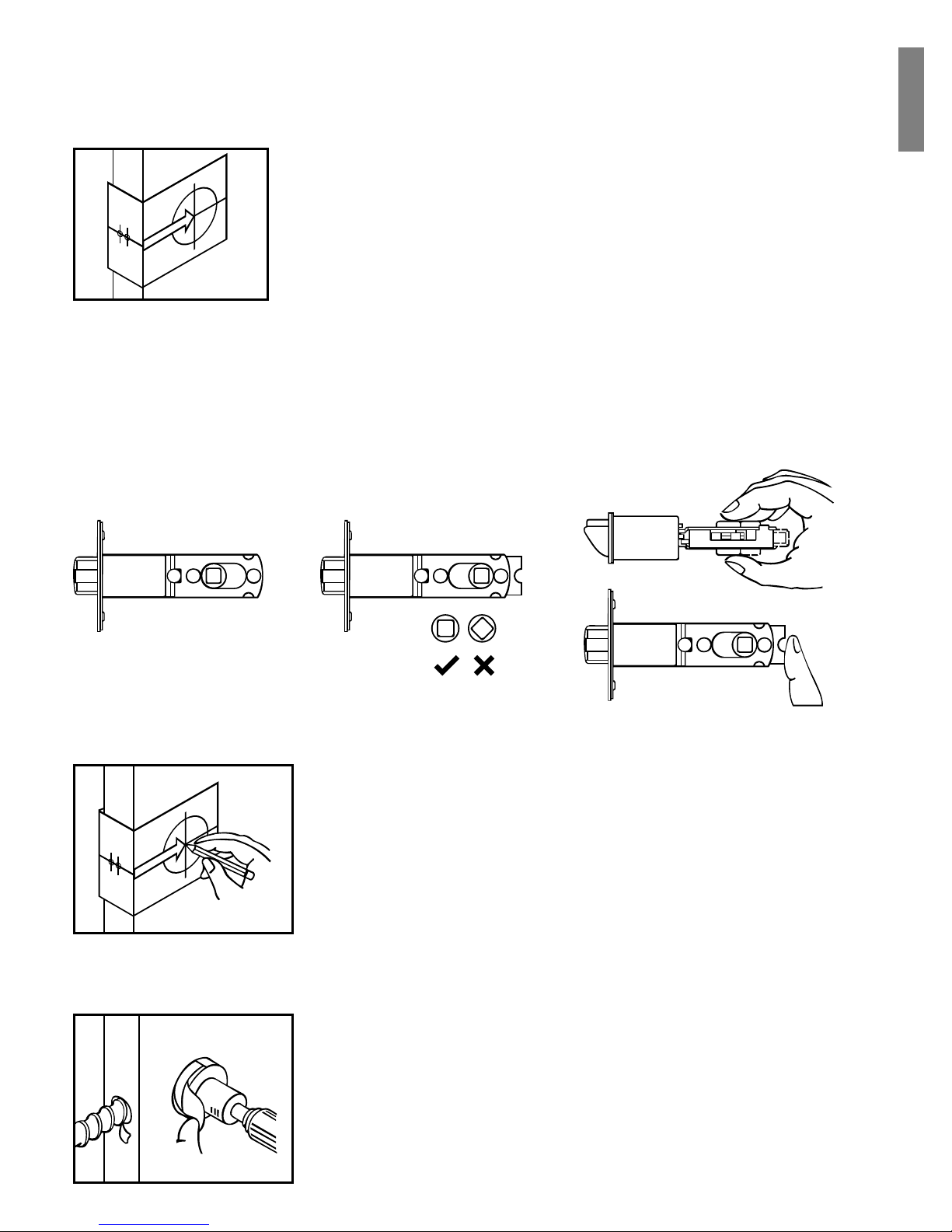
1. MARK THE DOOR WITH TEMPLATE
2. DRILL HOLES
The BACKSET is the distance between the center of
cross bore and edge bore of the door. Adjustable
latch fi ts both BACKSET of 2-3/8” (60mm) and 2-3/4”
(70mm). Please follow the steps shown below for
BACKSET adjustment.
a. The backset shown on the left is 60mm (2-3/8”).
b. Pull the cam toward right to extend the backset to 70mm (2-3/4”).
c. The backset shown in fi gure C is 70mm (2-3/4”). Pull the cam back to left
will return the backset to 60mm (2-3/8”).
Note: The shape of cam must be square.
abc
Select the height and backset as desired on the
boor face. Use the template as an indication to
the center of the circle on the door face and the
center of the door edge.
Using the marks as a guide to drill a hole
ø 2-1/8” (54mm) through the door face for the
lockset, then a hole of ø 1” (25mm) for latch.
English
4. INSTALL LATCH
a. Insert the latch and lay the faceplate against
the door edge. Use a pencil to mark it’s
perimeter, then take out the latch.
b. Chisel out the portion you have marked with
the pencil for about 4mm (5/32”) deep. Score
the area within the borders as clearly and
precisely as possible. Ensure the plate can
fi t fl ush with the door edge surface.
c. Insert the latch and tighten it with screws.
Be sure the holes for thru-bolts (next to the
adjustable cam) should be horizontally aligned.
d. There is no necessary to chisel the door edge
for the faceplate installation if you use the
drive-in latch. You may install it into the edge
bore directly. Be sure the bevel face the outside
assembly.
3. IDENTIFY DOOR HANDLING
Face the door from outside. The door is left handed if the hinge is on the
left hand side of the door, whereas the door is right handed if the hinge
is on the right-hand side of the door.
Interior
Exterior
Left Handed Right Handed
Door Hinge
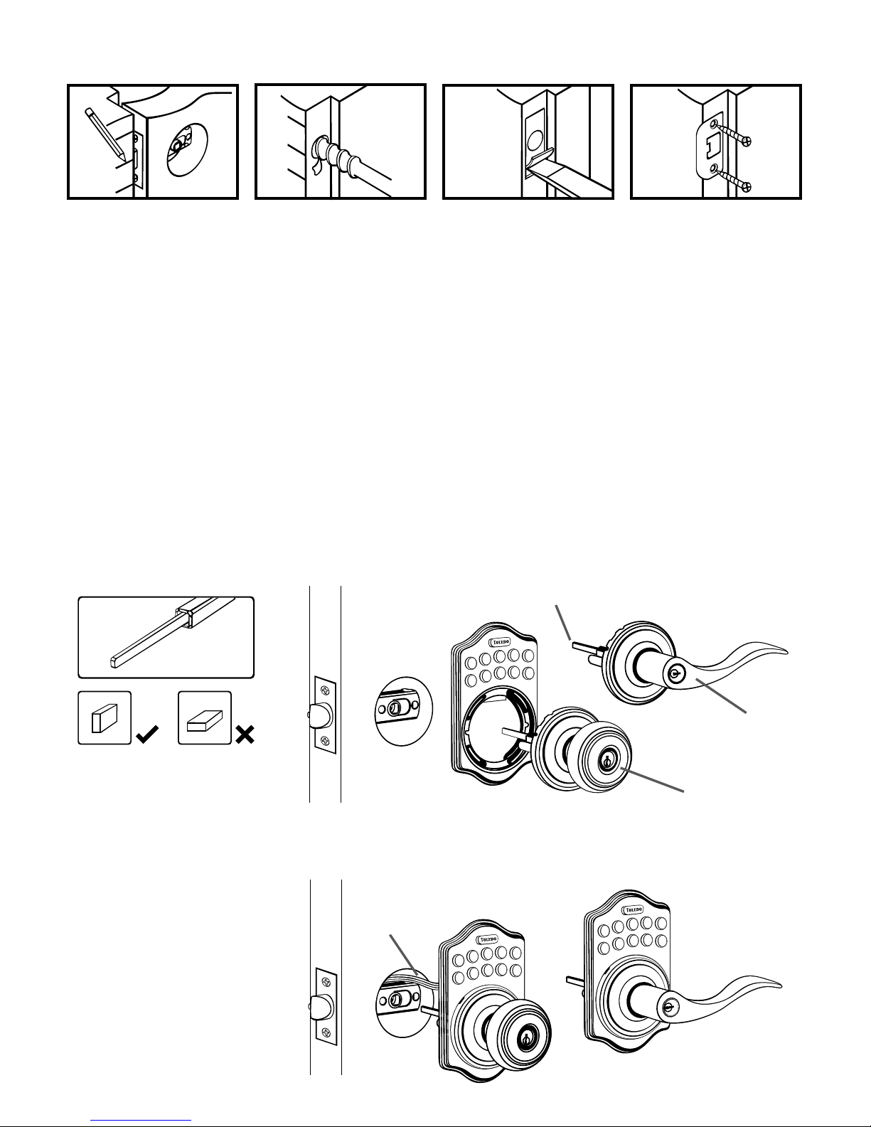
a. Half-close the door to lay the latchbolt against the door frame. Mark
the position of faceplate as an indication. Place the strike against the door
frame and mark it’s perimeter. Be sure the center of strike is perfectly
aligned with the center of faceplate.
b. Drill a ø 25.4mm (1”) hole with 13mm (1/2”) depth on the center of
strike outline. Then use the chisel to scrape out the door frame for 1.6mm
(1/16”) deep within your pencil mark. Ensure to chisel deep enough
to allow the strike lay fl ush with the frame surface.
c. Insert the strike and tighten it with screws.
Note: please use “tapping screws” for metal door.
a. Place the leverset / knobset against keyless pad with tailpiece in vertical
position inserted through cam of the latch.
b. Pass the IC wire over the latch to the interior side of door.
Tailpiece
Outside Knob
Outside Lever
IC wire
Tailpiece must be turned
in vertical position
5. INSTALL STRIKE
6. INSTALL KEYLESS ASSEMBLY
1
2
3
4
5
6
7
8
9
0
1
2
3
4
5
6
7
8
9
0
1
2
3
4
5
6
7
8
9
0
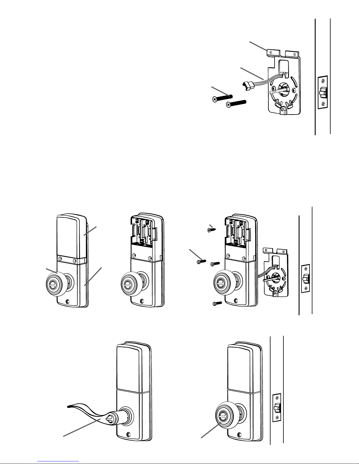
7. INSTALL INSIDE MOUNTING PLATE
8. INSTALL RECEIVER MODULE
Mounting
Plate
IC Wire
Screws
a.
c.
Turn
Piece
Receiver
module
Battery
cover
wood screw
screws
Inside
Lever
Inside
Knob
b.
Pass th IC wire through the hole
on the mounting plate and hold
the mounting plate with screws.
If outside lock assembly is lopsided,
please loosen the screws to adjust
it’s position and tighten the screws
again.
a. Remove the battery cover (push it up and pull it out).
b. Connect the IC wire and ensure the turn piece is horizontal, so that the
tailpiece is able to be engaged with the inside lever / knob. Then attach
receiver module to the door with screws. It is optional to use the attached
wood screw. (wood screws are only for wood door)
c. Insert 4(AA) 1.5v alkaline batteries and put the battery cover back to the
receiver module.
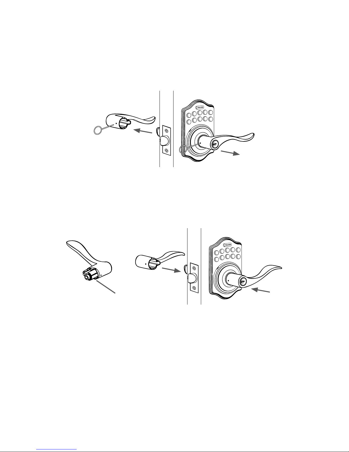
a. Be sure the levers are unlocked. Insert the provided pin wrench into the
small hole on the neck of lever and apply pressure to depress the catch and
pull out the lever from the stem. Follow the same steps to remove interior
lever and exchange the position of inside and outside levers.
b. Remove the cylinder from lever and insert it into opposite lever. Then
install the levers and make sure the small hole on the neck of lever aligns
over the catch perfectly. Rotate the levers to see if it operates well.
9. CHANGE LEVER HANDLING
1
2
3
4
5
6
7
8
9
0
1
2
3
4
5
6
7
8
9
0
Cylinder
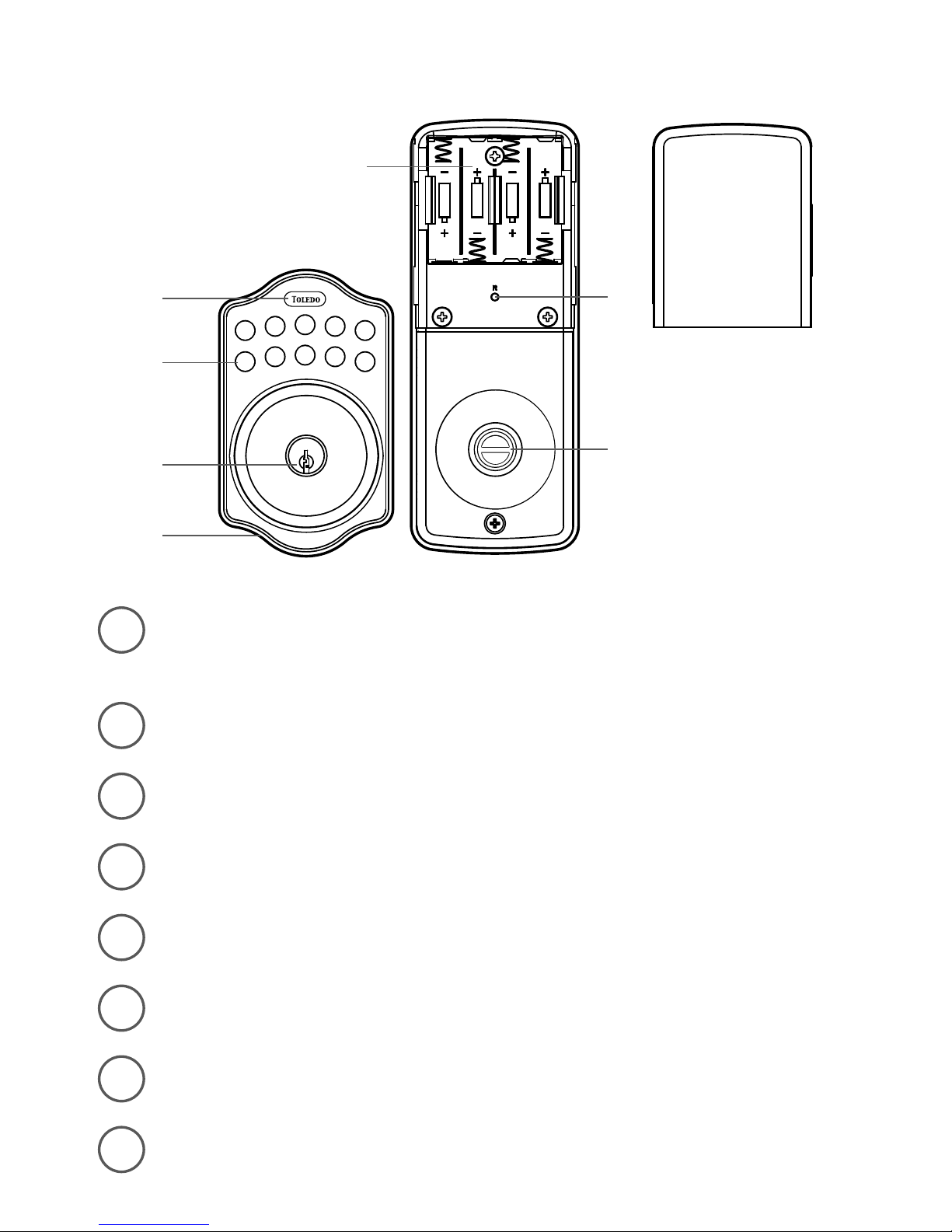
Programming Button
Programing Button is for entering codes, clearing errors and setting
functions.
Number Buttons
Input the user codes. Each user code is 4 to 10 digits in length.
Cylinder
Lock / Unlock the lockset from exterior.
Gasket
Prevent water permeating into lockset.
Battery Lid
Slide the lid to change the batteries.
Battery Holder
Holds four AA (1.5v) Alkaline batteries.
R. Button (Reset)
Restore defoult settings.
Turn- Button
Lock / Unlock the lockset from interior.
1
2
3
4
5
6
7
8
1
6
2
7
8
9
0
3
4
5
1
2
3
4
6
7
8
5
Ke
y
less Electronic Lock

Specifi cation/Function
1.Power
6V, four AA (1.5V) Alkaline batteries.
2.Low Battery
2-1 The batteries should be changed immediately once you see button 1 fl ashes
in red and hear 10 rapid beep sounds when press programming button.
2-2 All settings are retained in the memory and will not be affected even
if the battery is completely dead.
2-3 The lock still can be operated by key even there is a power outage.
3.llluminated lndicator
3-1 Button 1 fl ashes in green once when successful operation.
3-2 Button 1 fl ashes in green twice when successful programming.
3-3 Button 1 fl ashes in red 3 times when there is an operation error.
3-4 Button 1 fl ashes in red 5 times when codes input error, the system will shut down
for system protection (refer to17).
3-5 Button 1 fl ashes in orange 3 times when system has been restored to default setting.
3-6 Button 1 fl ashes in orange slowly while in programming mode.
4.Audible lndicator
4-1 1 beep sound indicates a successful operation.
4-2 2 long beeps indicate a successful programming
4-3 3 beeps indicate an operation error.
4-4 3 long beeps indicate that system has been restored to default setting.
4-5 5 beeps when codes input error, the system will shut down for system protection.
(refer to 17)
4-6 10 rapid beeps indicate the power of battery is low.
5.Programming Code
5-1 The preset Programming Code is 0000. Please change it into new one when fi rst
time operation.
5-2 Only one set of Programming Code for function setting.
5-3 Programming Code is only for function setting, you can not unlock the lockset
by entering Programming Code.
5-4 Programming Code is 4 to 10 digits in length.
5-5 Programming Code can be changed anytime if needed.

6.User Code
6-1 The preset user code is 1234.
Please delete it and create new one when fi rst time operation.
6-2 Up to 6 sets of User Codes can be saved.
6-3 User Code is only for unlocking the lock, without programming function.
6-4 User Code is 4 to 10 digits in length.
6-5 User Code can be deleted or added anytime if needed.
7.Delete lndividual User Code
7-1 User Codes can be deleted individually. You can re-set the same number
as code even it’s deleted before.
7-2 Programming Code is needed when deleting lndividual User Code.
8.Delete All User Codes At Once
8-1 All the User codes can be deleted at once. You can still reset the same numbers
as codes even they are deleted before.
8-2 Auto-locking and Keypad locking function will be invalid after deleting all User
Codes and the lock can only be operated by key. These functions will be restored
when recreate new User Codes.
8-3 Programming Code is needed when deleting all User Codes.
9.Temporarily Disable All User Codes
9-1 Auto-locking and Keypad locking function will be invalid when User Codes
are temporarily disabled. The lock can only be operated by key during the time.
9-2 Repeat the programming steps again to restore the auto-locking, keypad locking
function and User Codes.
10.Create a Disposable User Code
10-1 Disposable User Code will be no longer valid once being used.
10-2 You can reset same number as Disposal User Code again.
10-3 Programming Code is needed when creating a Disposable User Code.
11.Restore Preset Factory Code
11-1 You can restore Preset Factory Code by pressing “R” button on the interior receiver
module when you forget Programming Code or you want to cancel all previous
setting.
11-2 After restore the Programming Code will be 0000. The User Code will be 1234 again.

12.Unlock the door
12-1 The lockset will be unlocked by key or by pressing the User Code on keypad from
outside or by the interior turn-button.
12-2 To unlock the door on the keypad, enter the User Code and then press the
Programming/Enter button.
13.Lock the door
The lockset will be locked by key or by pressing the Programming Button on keypad
from outside or by the interior turn-button.
14.To Activate / Deactivate Auto-Locking Function
14-1 The lockset will automatically lock itself within 10 to 99 seconds when this function
is programmed.
14-2 This function is not preset at the beginning. It can be set if needed.
14-3 The preset delay-time is 30 seconds, you can adjust the time as you want.
14-4 Please repeat the same programming steps to cancel Auto-Locking function
when needed.
15.Toggle Mute On/Off
15-1 You will hear beep sounds when pressing keypad, programming or operating
errors. lt can be turned off if needed.
15-2 LED lllumination is still functioning when it is in mute. Therefore will not be any
warning alarm, we suggest not to mute the beeper if it’s not necessary.
15-3 Motor operating sound cannot be muted.
16.Code Protection Function
The system will shut down if entering unauthorized codes over 5 times.
The System will be operative again after 45 sec.
17.lllumination
The LED Keypad will light up when pressing any button for ease of operating in the dark.

Pass Code & Function Set up
1. It should be under unlock status while programming.
2. Please change default Programming Code (0000) and User Code (1234) before
function set up when fi rst time operation base on safety consideration.
3. LED fl ashes orange slowly while programming.
LED fl ashes green twice with 2 long beeps when correct input.
LED fl ashes red 3 times with 3 beeps when incorrect input. (You need to wait for 6
seconds or press programming button when incorrect input. then the system will be
operative again.)
4. Each programming step should be done within 6 seconds.
5. You can lock and unlock this product by either key or keypad.
Please refer to the following programming table for function set up.
Remark
1. We recommend to use alkaline battery in order to stabilize the power supply.
2. Do not mix alkaline battery with regular zinc-carbon ones or mixed brands.
3. Do not use any chemical liquid or lubricating oil with additives to clean the lock
body, it will damage the surface or even the mainboard.
4. lf there is any problem of the product, please contact your local retailer and send
back the product to us for repair or replacement.

Function Programming
Enter PC
Enter PC
Enter PC
Enter PC
Enter PC
Remark:
Up to 6 sets of User Code can be saved. User Code should be from 4 to 10 digits in length.
Remark:
Auto locking and keypad locking function will be invalid when User Codes are deleted.
The lock can only be operated by key during the time.
Remark:
The preset delay-time is 30 seconds, you can change the time by following instruction.
Repeat the steps to cancel the Auto-locking function.
Enter
New UC
Enter
New PC
Enter the
UC you
want to
delete
Add new User Code
Delete an existing User Code
Change Programming Code
Delete all User Code at once
Toggle Autolock on / off
Programing Code (PC)
User Code (UC)
TOLEDO
TOLEDO
TOLEDO
TOLEDO
TOLEDO
TOLEDO
TOLEDO
TOLEDO
TOLEDO
TOLEDO
TOLEDO
TOLEDO
TOLEDO
1
2
4
3
5

Enter PC
Enter PC
Enter PC
Enter PC
Press
Remark: 10-99 seconds delay-time available.
Remark: Repeat same steps to turn beeper On/Off. Led illumination is still functionimg
when it’s in mute. But there will be no warming alarm.
Remark: Auto-locking and Keypad locking function will be invalid when User Codes are
disabled. The lock can only be operated by key during the time. Repeat the steps to enable
the User Codes again.
Remark: Disposable code will be no longer walid once being used.
Remark: Press ‘‘R’’ button for over 5 seconds.
The programming will complete after you hear 3 long beeps
Set Autolock time delay
Toggle Mute on / off
Enable / Disable all User Code
Create a disposable User Code
Restore all preset lock settings
TOLEDO
TOLEDO
TOLEDO
TOLEDO
TOLEDO
TOLEDO
TOLEDO
TOLEDO
6
7
8
9
R
Enter
Seconds
(10-99)
Enter new
disposable
UC
TOLEDO
TOLEDO
Programing Code (PC)
User Code (UC)
Function Programming

ø 54mm (2-1/8”)
Mark ø 1” (25mm) hole
at center of door edge.
Fit here on door edge
FOR BACKSET 70mm (2-3/4”)
45
1-3/4” 1-9/16” 1-3/8”
40
TEMPLATE
35
FOR BACKSET 60mm (2-3/8”)

White Page

Cerradura Electrónica Ke
y
less
Instrucciones para instalación
1. Marque la puerta con el patrón
2. Taladre los huecos
El picaporte ajustable le sirve a ambas profundidades
de 2-3/8” (60mm) y 2-3/4” (70mm). Siga los pasos
ilustrados adelante para los ajustes de profundidad.
a. El picaporte mostrado a la izquierda es de 60mm (2-3/8”).
b. Hale la leva hacia la derecha para extender el “backset”
a 70mm (2-3/4”).
c. El backset mostrado en la fi gura C es de 70mm (2-3/4”). Empuje la leva
hacia la izquierda para regresarla al “backset” de 60mm (2-3/8”).
Nota: La forma de la leva debe estar cuadrada.
abc
Seleccione a su gusto la altura y la profundidad
en el frente de la puerta. Use el patrón como
guía para marcar el centro del círculo en el
frente de la puerta y el centro en el borde
de la puerta donde se instalará el picaporte.
Utilice las marcas como guía para taladrar
el hueco de ø 2-1/8” (54mm) en el frente de
la puerta. Luego utilice las marcas como guía
y taladre el hueco de ø 1” (25.4mm) para el
picaporte.
Español

4. Instale el picaporte
a. Introduzca el picaporte y asegure que esté
paralelo con el frente de la puerta. Marque
con un lápiz una línea alrededor de la placa
de metal del picaporte, luego retire el picaporte.
b. Con un formón, haga un corte profundo
de 5/32” (4mm) dejándose llevar por la línea
que marcó. Verifi que que la placa de metal
esté alineada con el borde de la puerta.
c. Introduzca el picaporte y ajuste con los
tornillos. Asegúrese que los huecos de los
tornillos pasantes (quedan al lado de la leva)
estén alineados horizontalmente.
d.Si utiliza el picaporte especial no necesita
cortar la madera de la puerta con el formón.
Puede ser instalado directamente a la puerta.
Asegure que el biselado quede hacia afuera.
3. Identifi que el manejo de la puerta
Acomódese de frente a la puerta desde el exterior de ésta. La puerta
es manejada a la izquierda si el gozne está en el lado izquierdo
de la puerta. Si el gozne está en el lado derecho de la puerta entonces
la puerta es manejada a la derecha.
Interior
Exterior
Lado izquierdo Lado derecho
Puerta Gozne

a. Para identifi car el centro del pasador: Cierre la puerta, en la base de la
placa de metal marque una línea horizontal en el pasador. Asegúrese que
el centro de la placa frontal y el centro del pasador estén alineados. Utilice
las marcas como guías fuera del pasador.
b. Utilice las marcas como guía y taladre el hueco de 1” (25.4mm) para
el picaporte. Con el formón haga un corte en la madera de 1/16” (1.6mm)
alrededor del pasador que permita que el pasador y el marco de la puerta
estén alineados.
c. Introduzca el pasador y ajuste con los tornillos.
Nota: Para puertas de metal use tornillos auto roscable.
a. Coloque el mango o el pomo en contra de los botones con la cola
en posición vertical atravesando la leva del picaporte.
b. Pase el cable IC atravez del picaporte hacia el lado interior de la puerta.
Cola
Pomo exterior
Mango
exterior
Cable IC
La cola debe estar
en posición vertical
5. Instale el pasador
6. Instale la maquinaria del sistema Keyless
1
2
3
4
5
6
7
8
9
0
1
2
3
4
5
6
7
8
9
0
1
2
3
4
5
6
7
8
9
0

7. Instale el interior de la placa de montura
8. Instale el módulo recibidor
Placa de
montura
Cable IC
Tornillos
a.
c.
Pieza
giratoria
Módulo
recibidor
Tapa de
batería
Tornillos
para
madera
Tornillos
Mango
interior
Pomo
interior
b.
Pase el cable IC a través del hueco
de cable de la placa base. Acomode
la placa de montura con los tornillos.
Si el montaje de afuera de la cerradura
está virado, suelte los tornillos para
arreglar la posición y vuelva a ajustar
los tornillos.
a. Remueva la tapa de la batería. (empuje hacia arriba y hale hacia fuera).
b. Conecte el cable IC y asegure que la pieza giratoria esté en posición
horizontal, para que la cola “tailpiece” conecte adentro de el mango
o el pomo. Luego sujete el módulo recibidor a la puerta con los tornillos.
(los tornillos de madera sólo se usan para puertas de madera).
c. Introduzca 4 baterías alcalina AA (1.5V) y tape la batería
del módulo recibidor.

a. Asegure que los mangos están abiertos. Inserte el pasador provisto en
el pequeño hueco localizado en el cuello del mango. Aplicar presión para
undir el seguro y halar el mango de la base. Repita las mismas indicaciones
para remover el mango interior. Intercambie de posición los mangos.
b. Remueva el cilindro del mango e inserte en el mango opuesto. Luego
instale los mangos y asegure que el hueco de los mangos alinee sobre
la base. Rote los mango para verifi car que operan correctamente.
9. Cambio de dirección de mango
1
2
3
4
5
6
7
8
9
0
1
2
3
4
5
6
7
8
9
0
Cilindro
Pasador

Programación de botones
La programación de botones es para entrar códigos, arreglar
errores, ajustar funciones y para bloquear códigos.
Botones de los números
Entrada del código de usuario. Cada código de usuario tiene
de 4 a 10 dígitos.
Cilindro
Cierra o abre el seguro desde el exterior.
Junta
Previene la entrada del agua en la cerradura.
Tapa de la batería
Deslice la tapa para cambiar las baterías o para restaurar el ajuste.
Caja de batería
Sujeta 4 baterías alcalinas AA (1.5V)
Botón R (Restauración)
Restaura la programación original.
Pieza giratoria
Cierra o abre el seguro desde el interior.
1
2
3
4
5
6
7
8
1
6
2
7
8
9
0
3
4
5
1
2
3
4
6
7
8
5
Ke
y
less Electronic Lock

Especifi caciones / Funciones
1.Energía
6V, cuatro AA (1.5V) baterías alcalinas
2.Batería agotada
2-1 Las baterías deben ser reemplazadas de inmediato una vez vea que el botón 1
se ilumine en rojo y escuche 10 sonidos cuando presione el botón de programación.
2-2 La memoria retiene todas las programaciones y no se verá afectada aunque la batería
esté completamente agotada.
2-3 La cerradura puede utilizarse con la llave aunque no haya energía.
3.Indicador iluminado
3-1 El botón 1 parpadea en verde una vez cuando la operación es exitosa.
3-2 El botón 1 parpadea en verde dos veces cuando la programación es exitosa.
3-3 El botón 1 parpadea en rojo tres veces cuando hay un error de operación.
3-4 El botón 1 parpadea en rojo cinco veces cuando hay error de código, el sistema
se apagará para su protección (referir a función 17).
3-5 El botón 1 parpadea en anaranjado 3 veces cuando el sistema ha sido restaurado
a su estado original.
3-6 El botón 1 parpadea en anaranjado lentamente cuando está en modo
de programación.
4.Audible lndicator
4-1 1 sonido “beep “ indica operación exitosa del sistema.
4-2 2 “beeps” largos indican programación exitosa del sistema.
4-3 3 “beeps” indica error en la operación del sistema.
4-4 3 “beeps” largos indican que el sistema ha sido restaurado a su estado original.
4-5 5 ”beeps” indican que se entró un código incorrecto. El sistema se apagará para
su protección (referir a función 17).
4-6 10 “beeps” rápidos indican que la carga de la batería es baja.
5.Código de programación
5-1 El código de programación preestablecido es 0000. Por favor bórrelo y cree su código
personal cuando utilice el sistema por primera vez.
5-2 Sólo puede tener un set de código de programación por función.
5-3 El código de programación es sólo para los ajustes de las funciones, no puede abrir
el seguro presionando el código de programación.
5-4 El código de programación es de 4 a 10 dígitos.
5-5 Puede cambiar el código de programación las veces que sea necesario.

6.Código de usuario
6-1 El código del usuario preestablecido es 1234. Por favor bórrelo y cree su código
personal cuando utilice el sistema por primera vez.6-2 Up to 6 sets of User Codes
can be saved.
6-3 El Código de usuario se utiliza sólo para activar la cerradura sin función
de programación.
6-4 El Código de usuario es de 4 a 10 dígitos.
6-5 El código del usuario puede ser borrado o cambiado las veces que sea necesario.
7.Borre el código del usuario individual
7-1 El código del usuario puede ser borrado individualmente. Puede reprogramar
el mismo numero como código aunque lo haya borrado.
7-2 Para borrar el código del usuario individualmente deberá introducir el código
de programación.
8.Borre todos los códigos de usuario a la vez
8-1 Todos los códigos de usuario pueden ser borrados a la misma vez.
Puede reprogramar los mismos números como códigos aunque los haya borrado
anteriormente.
8-2 Auto-locking and Keypad locking function will be invalid after deleting all User
Codes and the lock can only be operated by key. These functions will be restored
when recreate new User Codes.
8-3 Es necesario que introduzca el código de programación para borrar todos los códigos
de usuarios.
9.Todos los códigos de usuarios temporalmente inhabilitados
9-1 Cuando los códigos de usuarios están temporalmente inhabilitados las funciones
de auto cerrado y el panel de botones serán inválidas. La cerradura sólo puede
ser abrierta o cerrada con la llave.
9-2 Repeat the programming steps again to restore the auto-locking, keypad locking
function and User Codes.
10.Cree un código de usuario desechable
10-1 Este código de usuario desechable no será válido una vez utilizado.
10-2 Puede reprogramar el mismo número como código de usuario desechable.
10-3 Necesita introducir su código de programación para crear un código
de usuario desechable.

11.Restablezca el código del fabricante
11-1 Si se le olvida el código de programación o cuando quiera cancelar todos los ajustes
ya establecidos en el sistema puede restablecer un código fabricado establecido
presionando la tecla “R” en el modulo recibidor interno del sistema.
11-2 Después de restablecer el sistema, el código de programación volverá a ser 0000
y el código de usuario será 1234.
12. Abra la puerta
12-1 La cerradura será abierta usando la llave o entrando el código de usuario
en el panel de números en la parte exterior. También abre desde el interior girando
el mango o el pomo.
12-2 Para abrir el seguro de la puerta, introduzca el código de usuario y presione
el botón de programación (Toledo)
13.Cierre la puerta
La cerradura será cerrada usando la llave o entrando el código de usuario en el panel
de números en la parte exterior. También cierra desde el interior girando el mango
o el pomo.
14.Activar o desactivar la función de auto-cerrado
14-1 Cuando la función de auto cerrado se programa la puerta cerrará automáticamente
entre 10 a 99 segundos.
14-2 Esta función no viene programada. De ser necesario usted puede programarla.
14-3 El tiempo de espera pre establecido es de 30 segundos. Puede ajustarlo al tiempo
que desee.
14-4 Por favor repita los mismos pasos de programación para cancelar el auto cerrado
cuando sea necesario.
15.Interruptor de apagado y encendido en modo silencioso
15-1 Escuchará “beeps” cuando presione el panel de botones, cuando ocurran errores
de programación o de operación. Puede apagarlo si es necesario.
15-2 La iluminación de la bombilla LED continúa funcionando cuando el sistema esta
en modo silencioso aunque no estará activada la alarma de aviso. Sugerimos que
no ponga el beeper en el modo silencioso si no es necesario.
15-3 El sonido del motor operador no puede ser colocado en modo silencioso.

16.Función de código protector
La operación del sistema se detendrá si intenta entrar códigos no autorizados
por más de 5 veces. El sistema continuará operando luego de 45 segundos.
17.llluminación
El panel de llave LED se iluminará cuando presione cualquier botón para fácil manejo
en la oscuridad.
Código de entrada y confi guración
de funciones
1. Debe permanecer abierto mientras se programa.
2. La primera vez que vaya a operar el sistema cambie los códigos de programación
establecidos previamente (0000) y el código del usuario (1234) antes de confi gurar
las funciones.
3. Luz anaranjada parpadea lentamente cuando se está programando.
Luz verde parpadea dos veces junto a 2 “beeps” largos cuando el código es correcto.
Luz roja parpadea tres veces junto a 3 “beeps” cuando el código entrado es incorrecto.
(Necesita esperar por 6 segundos u oprimir el botón de programado
para que el sistema opere nuevamente)
4. Cada paso de programación deber ser realizado antes de 6 segundos.
5. Puede abrir o cerrar esta cerradura con la llave o con el código de entrada. Refi érase
a la tabla de programación para confi guración de funciones.
Nota importante
1. Recomendamos el uso de baterías alkalinas para estabilizar el suplido de energía.
2. No mezcle baterías alcalinas con baterías regulares de carbono y zinc.
Tampoco mezcle baterías de diferentes marcas.
3. No utilice ningún químico líquido o aceites lubricantes con aditivos para limpiar
la cerradura. Esto puede dañar la superfi cie o dañar el panel principal de la cerradura.
4. Si tiene algún problema con el producto por favor comuníquese con la tienda donde
lo compró y envíenos el producto para reparación o reemplazo.

Función
de la programación
Entre CP
Entre CP
Entre CP
Entre CP
Entre CP
Nota:
Se pueden grabar hasta 6 grupos de códigos de usuario. El código de usuario debe tener
de 4 a 10 dígitos.
Nota:
Cuando los códigos de usuario son borrados las funciones de auto-cerrado y el panel de
llave serán inválidas. El seguro funciona sólo por llave.
Nota:
El tiempo de retraso establecido previamente es de 30 segundos. Puede cambiar esto
siguiendo las instrucciones. Repita los pasos para cancelar la función de auto cerrado.
Entre
Nuevo
CU
Entre
nuevo
CP
Entre el CU
que desea
borrar
Añadir el nuevo código de usuario
Borrar un código de usuario existente
Cambiar el código de programación
Borrar todos los códigos de usuario a la vez
Activar o desactivar interruptor de auto-cerrado
Código de programación (CP)
Codigo de usuario (CU)
TOLEDO
TOLEDO
TOLEDO
TOLEDO
TOLEDO
TOLEDO
TOLEDO
TOLEDO
TOLEDO
TOLEDO
TOLEDO
TOLEDO
TOLEDO
1
2
4
3
5

Función
de la programación
Código de programación (CP)
Codigo de usuario (CU)
Entre CP
Entre CP
Entre CP
Entre CP
Oprima
Nota: El tiempo de retraso que hay disponible es de 10 a 99 segundos.
Nota: Repita los mismos pasos para Apagar/Encender el control. El panel de iluminación
LED continuará funcionando anque esté en función silenciosa. No hará aviso de alarma.
Nota: Cuando los códigos de usuario son borrados la función de auto-cerrado será
inválida. La cerradura se podrá utilizar sólo con la llave. Repita los pasos para habilitar
los códigos de usuario nuevamente.
Nota: El código de usuario disponible no será válido una vez haya sido usado.
Nota: Oprima el botón ‘‘R’’ por 5 segundos.
La programación será restaurada luego de 3 “beeps” largos
Ajuste el tiempo de retraso del auto cerrado
Activar o desactivar modo silencio
Habilitar o deshabilitar todos los códigos de usuario
Crear un código de usuario desechable
Restaurar programación original
TOLEDO
TOLEDO
TOLEDO
TOLEDO
TOLEDO
TOLEDO
TOLEDO
TOLEDO
6
7
8
9
R
Entrar
segundos
(10-99)
Entre
nuevo CU
desechable
TOLEDO
TOLEDO

ø 54mm (2-1/8”)
Marque el hueco de 1” (25mm)
en el centro del borde de la puerta
Acomodar esta parte
al borde de la puerta
Para profundidad de 70mm (2-3/4”)
45
1-3/4” 1-9/16” 1-3/8”
40
Patrón
35
Para profundidad de 60mm (2-3/8”)

White Page

Toledo & Co. (hereafter Toledo) warrants the product to be free
from defects in material and workmanship for a period of 12 month
from the original date of purchase. If you discover a defect in the
product covered by this warranty, we will repair or replace the item
at our option using new or refurbished components.
This warranty covers defects in manufacturing discovered while
using the products as recommended by Toledo rather than
occurred by act of God, and damages caused by misuse, abuse,
and unauthorized modifi cation.
Toledo will not be held liable for incidental or consequential losses
or damages to any act of God.
Service requirement shall subject to the presentation of this
Warranty Card to your distributor where you purchase from.
The Warranty Card will not be reissued if lost.
1. Warranty
2. Exclusions
3. Limited of liability
4. Reminder
Toledo & Co. PO Box 915
Dorado, PR 00646-0915
Tel: 787.807.3738
Fax: 787.807.3767
Toll free: 1.866.714.607
Limited Warranty Statement
Product:
Serial number:
Purchase date:
Name and address of distributor:
Keyless Electronic Lock

Toledo & Co. PO Box 915
Dorado, PR 00646-0915
Tel: 1.787.807.3738
Fax: 1.787.807.3767
Toll free: 1.866.714.6073
www.toledofi nelocks.com
info@toledofi nelocks.com
 Loading...