

Page 1

8572
DigiTOL®
PARTS
COUNTING
SCALE
Technical
Manual
and
Parts
Catalog
Page 2

TM008572 I01
Page 3

INTRODUCTION
This publication is provided solely as a guide for individuals who have received Toledo
Technical Training in servicing the Toledo product.
Information regarding Toledo Scale technical training may be obtained by writing to:
Toledo Scale
Training Center
P.O. Box 1705
Columbus OH 43216
(614) 438-4400
FCC NOTE
This equipment has been tested and found to comply with the limits of the United States of
America FCC rules for a Class A digital device, pursuant to Part 15 of the FCC Rules and
the Radio Interference Regulations of the Canadian Department of Communications.
These limits are designed to provide reasonable protection against harmful interference
when the equipment is operated in a commercial environment. This equipment generates,
uses, and can radiate radio frequency energy and, if not installed and used in accordance
with the instruction manual may cause harmful interference to radio communications.
Operation of this equipment in a residential area is likely to cause harmful interference in
which case the user will be required to correct the interference at his own expense.
IMPORTANT
It is most important that the correct part number is used when ordering. Part orders are
machine processed, using only the part number and quantity as shown on the order.
Orders are not edited to determine if the part number and description agree.
TOLEDO SCALE RESERVES THE RIGHT TO MAKE
REFINEMENTS OR CHANGES WITHOUT PRIOR NOTICE
Page 4

Page 5
PRECAUTIONS
•
•
•
•
this manual before operating or
READ
servicing this equipment.
ALWAYS REMOVE POWER
seconds
disconnecting any internal harnesses.
Failure to observe these precautions may
result in damage to, or destruction of the equipment.
ALWAYS
DO NOT
scale base to the equipment with power
connected or damage will result.
BEFORE
take proper precautions when handling static sensitive devices.
connect or disconnect a load cell
and wait at least 30
connecting or
WARNING
DISCONNECT A LL P OW E R
TO THIS UNIT BEFORE
REMOVING THE FUSE
OR SERVICING.
WARNING
ONLY PERMIT QUALIFIED PERSONNEL TO
SERVICE THIS EQUIPMENT. EXERCISE CARE
WHEN MAKING CHECKS, TESTS, AND
ADJUSTMENTS THAT MUST BE MADE
WITH POWER ON.
•
•
•
•
this manual for future reference.
SAVE
DO NOT
tamper with this equipment.
ALWAYS DISCONNECT
power source before servicing.
CALL
information, and service.
allow untrained personnel to operate, clean, inspect, maintain, service, or
this equipment from the
METTLER TOLEDO for parts,
CA UTION
OBSERVE PRECAUTIONS
FOR HANDLING
ELECTROSTATIC
SENSITIVE DEVICES
Page 6

Table of Contents
1. GENERAL DESCRIPTION
1.1. STANDARD FEATURES..................................................................................................................................... 1
1.2 OPTIONAL FEATURES...................................................................................................................................... 1
1.3. STATEMENT OF PERFORMANCE................................................................................................................... 2
1.4. ACCURACY CONSIDERATIONS....................................................................................................................... 2
2. SYSTEM DESCRIPTION
2.1. INTERNAL FUNCTIONS..................................................................................................................................... 3
2.2. OPTIONAL KITS.................................................................................................................................................. 3
2.2.1. Bar Code.................................................................................................................................................... 3
2.2.2. Remote Scale Input.................................................................................................................................... 3
2.2.3. Battery Power Operation ........................................................................................................................... 4
3. SPECIFICATIONS
3.1. ELECTRICAL....................................................................................................................................................... 5
3.1.1. Power Requirements ................................................................................................................................. 5
3.1.2. Conducted and Radiated Emissions ......................................................................................................... 5
3.1.3. Radio Frequency Interference ................................................................................................................... 5
3.2. ENVIRONMENTAL.............................................................................................................................................. 6
3.2.1. Temperature Specification......................................................................................................................... 6
3.2.2. Hazardous Areas ....................................................................................................................................... 6
3.3. PHYSICAL SPECIFICATIONS ........................................................................................................................... 6
3.3.1. Appearance and Dimensions..................................................................................................................... 6
3.3.2. Internal Scale Platter.................................................................................................................................. 6
3.3.3. Shipping Information.................................................................................................................................. 6
3.4. DATA INTERFACE............................................................................................................................................... 7
3.4.1. Data Output................................................................................................................................................ 7
3.4.2. Data Input................................................................................................................................................... 7
3.5. CONFIGURATION GUIDE.................................................................................................................................. 7
.................................................................................................................................................. 5
................................................................................................................................. 1
.................................................................................................................................... 3
4. INSTALLA TION INSTRUCTIONS
4.1. UNPACKING AND SETUP.................................................................................................................................. 9
4.1.1. Unpacking Instructions for Low Capacity Scale (for 8572-0002, 1002 versions only) ............................. 9
4.1.2. Level the Scale Base ................................................................................................................................ 10
4.1.3. Install All Optional KOPs........................................................................................................................... 10
4.1.4. Initial Power Up Sequence........................................................................................................................ 10
4.2. PROGRAMMING PROCEDURE....................................................................................................................... 11
4.3. SETUP QUICK REFERENCE............................................................................................................................ 12
4.4. CALIBRATION GROUP PROGRAMMING........................................................................................................ 14
4.4.1. Internal Scale Setup and Calibration ........................................................................................................ 15
4.4.2. Remote Scale Shift Adjust ........................................................................................................................ 18
4.4.3. Remote Scale Setup and Calibration ....................................................................................................... 18
4.5. ZERO, MOTION, AND FILTERING GROUP PROGRAMMING....................................................................... 21
4.6. TARE GROUP PROGRAMMING ...................................................................................................................... 23
4.7. ACCUMULATOR GROUP PROGRAMMING.................................................................................................... 24
4.8. SAMPLE GROUP PROGRAMMING ................................................................................................................. 25
4.9. DISPLAY GROUP PROGRAMMING................................................................................................................. 27
4.10. SERIAL I/O GROUP PROGRAMMING........................................................................................................... 30
4.10. INTERNATIONAL GROUP PROGRAMMING ................................................................................................ 32
................................................................................................................... 9
Page 7

Table of Contents
5. OPERATING INSTRUCTIONS
5.1. DISPLAY FORMAT AND LEGENDS ................................................................................................................. 35
5.2. KEYBOARD OPERATION.................................................................................................................................. 36
5.2.1. Order Independent Mode Key Definitions................................................................................................. 37
5.2.2. Order Dependent Mode Key Definitions................................................................................................... 37
5.3. PUSHBUTTON ZERO........................................................................................................................................ 38
5.3.1. Zeroing the Gross Scale............................................................................................................................ 38
5.3.2. Zeroing the Sample Scale......................................................................................................................... 38
5.4. COUNTING OPERATION .................................................................................................................................. 39
5.4.1. Order Dependent Counting Modes........................................................................................................... 39
5.4.2. Order Independent Counting Mode .......................................................................................................... 43
5.5. SAMPLE ENHANCEMENT AND COUNTING WEIGHT RANGE PARAMETERS.......................................... 44
6. INPUT AND OUTPUT CONNECTORS AND INTERFACING
6.1. PRINTER INTERFACE SPECIFICATIONS....................................................................................................... 47
6.1.1. Data Format............................................................................................................................................... 47
6.1.2. Printer Interconnect................................................................................................................................... 49
6.1.3. ASCII Remote Input .................................................................................................................................. 49
6.2. REMOTE SCALE BASE INTERFACING........................................................................................................... 49
6.2.1. Remote DigiTOL® Scale Base Connection............................................................................................. 50
6.2.2. Remote Analog Scale Base Connection................................................................................................... 51
7. PREVENTIVE MAINTEN ANCE
7.1. TROUBLESHOOTING........................................................................................................................................ 53
7.2. ERROR CODES ................................................................................................................................................. 54
7.3. POWER SUPPLY VOLTAGE CHECKS ............................................................................................................ 55
7.3.1. External Power Supply.............................................................................................................................. 55
7.3.2. +12 VDC Logic Supply.............................................................................................................................. 55
7.3.3. +20 VDC Supply........................................................................................................................................ 56
7.3.4. +5 VDC Logic Supply................................................................................................................................ 56
7.3.5. +12.5 VDC Analog Load Cell Excitation ................................................................................................... 56
7.4. LOAD CELL REPLACEMENT............................................................................................................................ 57
7.5. OVERLOAD STOP ADJUSTMENT ................................................................................................................... 58
7.5.1. Low Capacity Overload Adjustment (8572-0002, 0003, 1002, 1003) ...................................................... 59
7.5.2. Higher Capacity Overload Adjustment (8572-0004, 0005, 0006, 1004, 1005, and 1006)....................... 59
7.6. KEYBOARD REPLACEMENT............................................................................................................................ 60
7.7. LOGIC PCB REPLACEMENT............................................................................................................................ 62
7.8. RECOMMENDED SPARE PARTS .................................................................................................................... 62
7.9. OPTIONAL KITS................................................................................................................................................. 63
......................................................................................................................... 35
.............................................................. 47
....................................................................................................................... 53
8. PARTS CATALOG
8.1. EXTERIOR VIEW LOW CAPACITY VERSIONS (Factory Numbers 8572-0002, 1002).................................. 65
8.2. EXTERIOR VIEW HIGHER CAPACITY VERSIONS
(Factory Numbers 8572-0003, 0004, 0005, 0006, 1003, 1004, 1005, and 1006) ............................................. 66
8.3. BOTTOM VIEW .................................................................................................................................................. 67
8.4. PCBs AND TOP COVER.................................................................................................................................... 68
8.5. INTERIOR OF BASE .......................................................................................................................................... 69
................................................................................................................................................ 65
9. INTERCONNECT DRAWING
........................................................................................................................... 70
Page 8

1. GENERAL DESCRIPTION
The Toledo Scale DigiTOL® Model 8572 Parts Counting Scale is a high resolution scale designed f or use in m ost
industrial environments. The 8572 can be used with one analog or DigiTOL® remote scale base, offer ing f lexibility
and consistently accurate parts counting perfor mance.
HAZARDOUS by the National Electric Code (NEC) because of combustible or explosive atmospheres, or in
areas that contain extreme dust, moisture, or corrosive materials.
1.1. STANDARD FEATURES
6
Internal Toledo® DigiTOL® load cell in 5, 10, 25, 50, and 100 lb capacities with one part in 500,000 internal
resolution.
6
Low power LCD (Liquid Crystal Display) with programmable cursors and two, six digit displays for weight data
and counting information.
6
20 position sealed polycarbonate keyboard with embossed edges and tactile feedback.
6
Bidirectional RS-232 serial port for printer or com puter interfac ing with single character ASCII input f or rem ote
print, tare, clear, zero, and accumulator functions.
6
Low power CMOS circuitry to maximize optional battery life.
6
12 VDC 0.6 A wall transformer to power the standard 8572.
The 8572 MUST NOT be used in areas classified as
6
Automatic Average Piece W eight (APW ) enhancement. If select ed, the 8572 automatically recalculates the
APW continuously up to 4% of scale capacity.
6
Selectabl e sample si ze.
6
Pushbutton zeroing (±2% or ±20% of scale capacity) with automatic zero maintenance.
6
Independent or dependent modes of counting operation.
6
A 16 digit ID for transaction identification.
6
A single register accumulator for weight or count data.
6
A resetable consecutive number register that increments every time an accumulation is performed.
6
All setup parameters and scale operating features including calibration are easily configured through the
standard keyboard.
1.2 OPTIONAL FEATURES
6
12.5 VDC 1.5 A wall mount transformer is required to power the 8572 if any optional equipment is installed in
the 8572.
6
Input for one DigiTOL® or analog scale base, with 1 part in 500,000 internal resolution.
6
Bar code input by means of a hand held wand or scanning gun.
6
Internal and/or external batteries for applications requiring operation without AC power.
Page 9

1.3. STATEMENT OF PERFORMANCE
The performance of any count-by-weighing scale is dependent on uniformity of piece weight, the number of
pieces in the sample, the weight of an individual piece and the per cent of rated load plac ed on the scale for a
sample. Count accuracy is also dependant upon correct operation of the scale.
The 8572 high resolution parts counting scale significantly reduces count errors caused by the operator. In
most applications, it provides better practical accuracy than either hand counting or other mechanical
techniques. W ith the proper scale selection, c ount accuracy of ± one piece is attainable. However the most
significant variable is non-uniformity in the weight of the parts to be counted; this variable is beyond the contr ol
of the scale.
1.4. ACCURA CY CONSIDERATIONS
Counting accuracy is determined prim arily by two factors: Sample size as a percentage of full sc ale capacity
and variation in weight from piece to piece of the parts to be counted.
The first factor is the most f requent cause of counting inac curacy because of the user's des ire to hand count
the minimum possible num ber of sample pieces. Using too s mall a sample size results in limited accuracy.
For example, with a sample weight equal to 0.05% of full scale c apacity, the internal sample weight resolution
is ±1 part in 250, therefore counting acc uracy will be limited to ±0.4% in this example. Use of a sample size
that is a higher percentage of full scale capacity will result in improved counting accuracy.
The overall count accuracy can be severely affected if the pieces used for the sample are not truly
representative of the average piece weight. The sec ond factor is not under the control of the par ts counting
scale, but this factor can be m inimized by using the largest practical sam ple size possible and resampling
when counting different lots of the same material.
2
Page 10

2. SYSTEM DESCRIPTION
The 8572 Logic PCB provides a DC voltage to the digital load cell which responds with numeric values proportional
to the weight applied to the platter. This weight information is then used to determine the average piece weight and
corresponding piece count. Setup parameters and calibration are ac ces sible via the fr ont k eyboard, so no internal
access is required to configure the 8572. Setup and calibration data is stored in non-volatile m emory to prevent
memory loss from occurring during a power outage.
2.1. INTERNAL FUNCTIONS
The basic 8572 consists of four major components. These are:
DigiTOL® Load Cell
6666
the Logic PCB.
Logic PCB -
6666
the keyboard, communic ates with the DigiTOL® load cell, dr ives the display PCB, pr ovides a bidir ectional
RS-232 serial printer port, and supplies connections for optional accessories.
Keyboard -
6666
covered with an embossed polycarbonate overlay that provides ridges to separate active key areas. The
functions available are tare entry, sample or APW entry, numeric ID entry, clearing of data, printing,
zeroing of the scale, scale selection, recall access and setup selection.
Display PCB
6666
display weight or count information. Six, 0.44" (11 mm) high, seven-segm ent digits display net weight,
percentage of accuracy, consecutive num bering, average piece weight, or total counts. The LCD dis play
also provides low battery and status symbols and eight programmable cursors to indicate display or
operating mode.
Contains the power supply and logic circuitry required to operate the scale. This PCB scans
The sealed membrane, four by five matrix k eyboard with domed keys for tactile feedback , is
- Contains the LCD (liquid crystal display). Six, 0.7" (18 mm ) high, seven- segm ent digits
- A single point loading, high resolution load cell that c ommunic ates weight data to
2.2. OPTIONAL KITS
The standard 0.6 A, 12 VDC power supply (*135156 00A), MUST be replaced with the optional 1.5 A, 12.5
VDC power supply (*135693 00A) when any optional KOP is installed in the Model 8572.
2.2.1. Bar Code
Scanning of bar code data can accomplished by means of the bar code wand kit or the bar c ode s canning
gun kit. The 8572 can read Code 39, Interleaved 2 of 5, or Codabar form at bar code data. Tare, APW ,
and up to 16 digits of alphanumeric ID c an be scanned into the 8572. The 8572, when coupled with the
Model 8860 thermal printer, can print up to six lines of bar code and/or human readable data on an
adhesive label in a variety of formats.
2.2.2. Remote Scale Input
The 8572 remote scale input provides 1 part in 500,000 resolution and approx im ately nine weight updates
per second. The 8572 can accommodate one remote scale base of either the DigiTOL® or analog type.
The remote DigiTOL® scale PCB is com patible with all Toledo Scale DigiT OL® scale bas es including the
Model 2157 floor scale (digital j-box), also referred to as DigiTOL® POWER MODULE. The remote
analog scale PCB can supply excitation voltage for up to four 350 ohm load cells and is com patible with
both 2 mV/V and 3 mV/V analog load cells.
NOTE: The 8572 requires that four load cells be used with the digital j-box. The Model 2157 floor scale (digital
j-box) provides up to 1 part in 280,000 resolution.
2.2.3. Battery Power Operation
3
Page 11
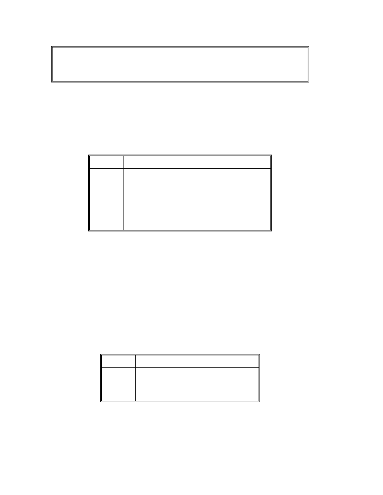
2.2.3.1. Battery Powered Operating Time
The internal battery kit allows operation of the 8572 when AC power is not available. The internal
battery provides up to 8 hours of power. The battery can be removed by means of an access cover
located on the back of the 8572. T he normal rec harge time is approximately 12 hour s with the 8572
turned off. The exter nal battery pack provides up to 32 hours of power and is easily replaced with a
freshly charged external battery pack for applications requiring extended use without AC power. T he
normal battery recharge time is approximately 16 hours with the 8572 turned off.
Battery Option
Installed
Internal 8 hours 3 hours (Not recommended) 2 Hours (Not Recommended)
External 32 hours 16 Hours 8 Hours
Table 2-1 Recommended Battery Powered Operating Time With Example Configurations
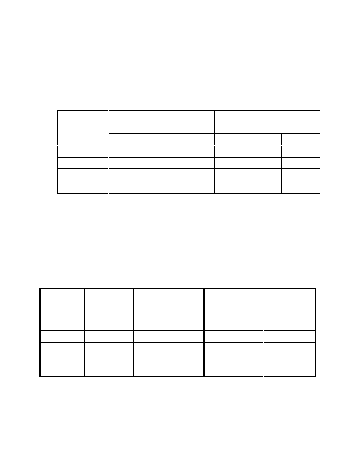
2.2.3.2. Battery Service Life Considerations
Battery service life is a major f ac tor in es timating the maximum operating tim e of a c harged battery.
The internal and external battery options use a lead/acid "gel" cell type of battery that is similar to
an automobile battery.
completely discharged on a repetitive basis
deeply a battery is routinely discharged and how many times the battery can be recharged. A
battery is considered to have exceeded its working lif e when the fully charged capacity is less than
50% of the original rated capacity. Refer to Table 2-1.
No other
Options Installed
Remote DigiTOL® Scale
Bar Code KOP
Lead/acid batteries lose charge capacity more quickly if they are
. There is an inverse relationship between how
Remote Analog Scale Base
(4-350 Α Load Cells)
To maximize the working life of a
battery, recharge the battery on a the
basis of how many hours the scale has
been in use rather than running until the
8572 powers itself down. If a particular
scale configuration results in a
maximum battery charge life of 24
hours before the battery is exhausted,
then the battery pack should normally
be used for 8 hours and then
recharged. Extra battery packs and an
external battery charger are available to
permit continuous battery powered
operation. Following this procedure will
greatly increase the service life of the
battery and prevent premature battery
failure.
a battery at temperatures above 860 F (300 C) shortens service life considerably.
Figure 2-1 Number of Recharge Cycles Related to Battery Discharge Depth
Always recharge batteries after use. Batteries stored in a discharged state may refuse to take a
charge.
Storing batteries at 500 F (100 C) or below extends shelf life before recharging is necessary.
Batteries should be recharged every six months of s torage (when stored at room temperature) .
3. SPECIFICATIONS
4
Operating and storage conditions also
influence battery service life. Operating
Page 12
3.1. ELECTRICAL
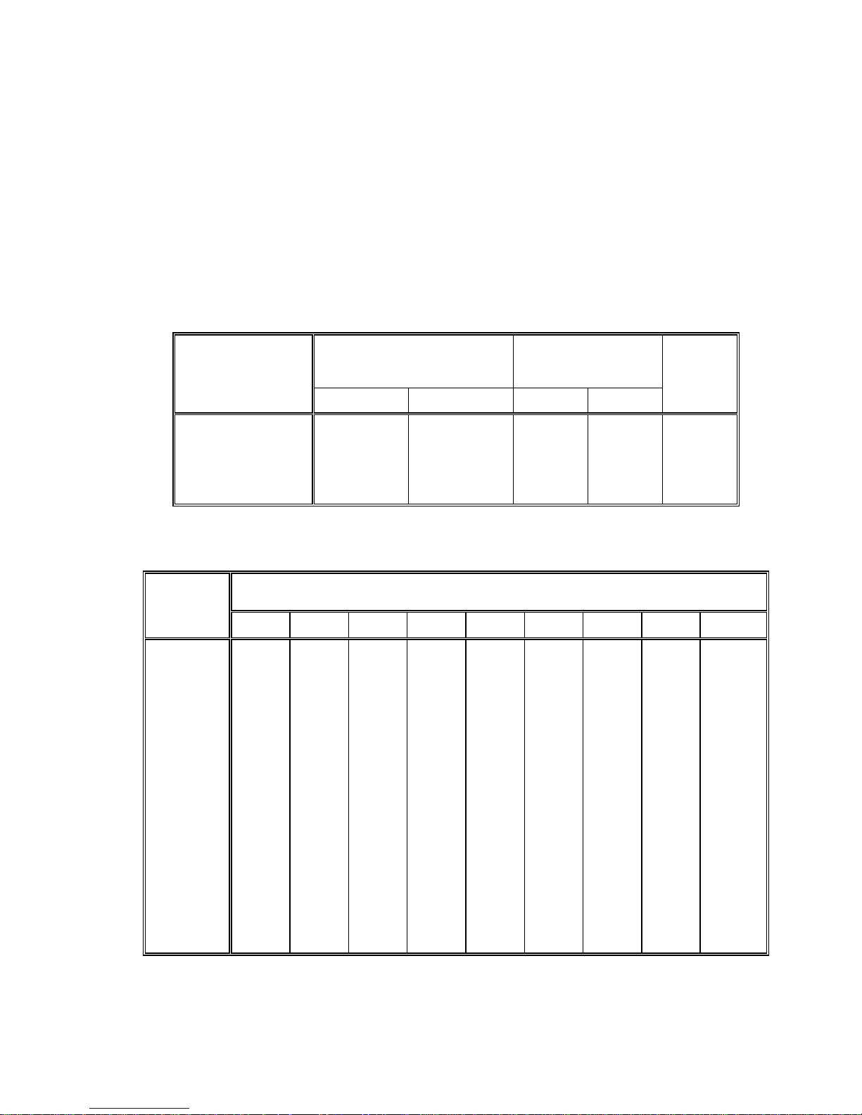
3.1.1. Power Requirements
The 8572 operates at 120 VAC (+10%, -15%) 60 Hz. Export versions of the 8572 oper ate on 220 VAC,
50 Hz. Power to the 8572 is provided by means of an external 0.6 A / 12 VDC power supply. Power
consumption for the basic 8572 without any options installed is four watts.
The 8572 meets the NIST H-44, Canadian Gazette Part 1, and OIML-SP7/SP2 line voltage variation
specifications.
Line Voltage
AC Line Voltage Line Frequency in Hz
Variation
Specification
Minimum Nominal Maximum Minimum Nominal Maximum
NIST H-44 100 120 130 59.5 60 60.5
Canadian 108 120 132 58.8 60 61.2
OIML-SP7/SP2
102
187
204
120
220
240
132
242
264
58.8
49.0
49.0
60
50
50
61.2
51
51
Table 3-1 AC Line Power Voltage Specifications
3.1.2. Conducted and Radiated Emissions
The 8572 meets or exceeds FCC docket 80-284 for conducted and radiated emissions requirements.
The 8572 meets or exceeds the VDE 0871 class B specification for conducted and radiated emissions.
3.1.3. Radio Frequency Interference
The 8572 meets U.S.A., Canadian, VDE 0871 class B, and U.K. requirements f or RFI susceptibility as
listed below with a maximum of one display increment of change.
Radio
U.S.A. Canadian VDE 0871 Class B U.K.
Interference
Frequency
Field Strength Transmitted Power at
27 MHz 3 volts/meter 4 watts at 2 meters 3 volts/meter 10 volts/meter
144 MHZ N.A. N.A. 3 volts/meter N.A.
169 MHz 3 volts/meter N.A. 3 volts/meter 10 volts/meter
464 MHZ 3 volts/meter 4 watts at 2 meters 3 volts/meter 10 volts/meter
Field Strength Field Strength
Specified Distance
Table 3-2 Radio Frequency Interference Continued
(N.A.) Not Applicable
5
Page 13

3.2. ENVIRONMENTAL
The 8572 is intended for use in a general purpose atmosphere. It is intended for indoor applications where
dirt, oil or water is not present. The 8572 is not designed for "hose-down" applications. Typical examples of
misapplication of the scale include, but are not limited to: Immersion in liquid, hosedown, corrosive
chemicals.
3.2.1. Temperature Specification
The 8572 has an operating temperatur e range of from 10 0 to 40 0 C, (50 0 to 104 0 F) at 10 to 95%
relative humidity, non-condensing. The 8572 has a storage temperature range of -40 0 to 60 0 C, (-40
to 140 0 F) at 10 to 95% relative humidity, non-condensing.
3.2.1.1. Internal DigiTOL® Load Cell
The 8572 internal scale has a zero temper ature coefficient of 24 PPM/0C and a span temperature
coefficient of 23 PPM/0C.
3.2.1.2. Remote Analog Scale PCB
The optional analog scale PCB has a zero temperature coefficient of 0.1 uV/0C and a span
temperature coefficient of 6 PPM/0C
3.2.2. Hazardous Areas
0
In locations classified as hazardous by the National Electrical code (NEC) because of combustible or
explosive atmospheres or materials, special precautions are required.
DO NOT USE THE 8572 IN THESE LOCATIONS
3.3. PHYSICAL SPECIFICATIONS
3.3.1. Appearance and Dimensions
The 8572 enclosure is fog white with a black platter ass em bly and multi-c olor k eyboard. the unit is 5.3"
(135 mm) high, 14.7" (375 mm) wide and 14.6" (370 mm) deep. The standard 8572 weighs
approximately 20 lb (9.1 kg). The bas e and sub-platter are made from die- cast aluminum . The 8572
uses a single point loading, moment-insensitive load cell. The cover and bezel are made of heavy
structural plastic. A level indicator bubble is mounted in the sub-platter which can be viewed by
removing the platter.
3.3.2. Internal Scale Platter
The 5 lb capacity scale has an 8" X 8" (205 m m) plastic platform . The 10, 25, 50, and 100 lb capacity
scales has a 14.5" wide (370 mm) X 10.8" deep (275 mm) painted steel platter.
3.3.3. Shipping Information
Approximate shipping weight is 22 lb (10 k g). Carton dimensions ar e 9" (230 mm) X 19" (485 mm) X
19" (485 mm).
.
3.4. DATA INTERFACE
6
Page 14

The 8572 supplies a bidirectional RS-232 printer port standard. The baud rate is selectable from 300 to
9600 baud and parity is selectable as even, odd, or parity bit always a "0". All data is in a 10 bit fram e: 1
start bit, 7 ASCII coded data bits, 1 parity bit and 1 stop bit. The 8572 printer port is powered by the
external RS-232 device connected to the 8572. Both the transmit and receive RS-232 data lines of the
8572 printer port must be connec ted to a true RS- 232 exter nal devic e to permit data output. No hands hak e
lines are provided on the printer port.
3.4.1. Data Output
When a print request oc curs (caus ed by pressing the
an ASCII "P" into the printer port), the 8572 will output data unless output is inhibited. Data output will
be inhibited by an unstable weight reading (scale "in motion"), an out of range weight reading (under
zero or over capacity) or if the 8572 is in the expanded weight display mode. If repeat print is disabled
the 8572 will output data only once per weighment after which the load on the scale must be removed
and a new load placed on the scale before data can be output.
A selectable checksum character can be added to the data output to perm it detection of transmission
errors. A selectable ASCII <SO> (shif t out) charac ter can be added to the data output to request lar ge
print size in the Model 8806 and 8860 printers.
3.4.2. Data Input
The 8572 printer port can be configured to permit an external device to control the 8572. Upper case,
ASCII characters ("C", "P","T" and "Z") received into the printer port are equivalent pressing to the
CLEAR, PRINT, TARE
transmitted and or cleared by ASCII characters.
3.5. CONFIGURATION GUIDE
Factory Number Pounds Capacity Metric Capacity Load Cell Capacity
120 VAC, 60 Hz
U.S.A. and
Canadian
Versions
8572-0002
8572-0003
8572-0004
8572-0005
8572-0006
and
PRINT
key, an autoprint operation or by receiving
ZERO
keys on the 8572 keyboard. The accumulator total can be
5 X 0.001 lb
10 X 0.002 lb
25 X 0.005 lb
50 X 0.01 lb
100 X 0.02 lb
2.5 X 0.0005 kg
5 X 0.001 kg
10 X 0.002 kg
25 X 0.005 kg
50 X 0.01 kg
3.75 kg
7.5 kg
15 kg
30 kg
60 kg
220 VAC, 50 Hz
Europe and
General Export
Versions
8572-1002
8572-1003
8572-1004
8572-1005
8572-1006
5 X 0.001 lb
10 X 0.002 lb
25 X 0.005 lb
50 X 0.01 lb
100 X 0.02 lb
2.5 X 0.0005 kg
5 X 0.001 kg
10 X 0.002 kg
25 X 0.005 kg
50 X 0.01 kg
Table 3-3 Factory Number Configuration
7
3.75 kg
7.5 kg
15 kg
30 kg
60 kg
Page 15

- For Your Notes -
8
Page 16
4. INSTALLATION INSTRUCTIONS
Examine the shipping box for damage.
Open the box, remove the scale, and plac e the scale on a f lat, level, stable surf ace. Save the shipping box f or
future use.
IMMEDIATELY make a claim with the carrier if damage is found.
2 CAUTION!
Do not lift the scale by the platter or sub-platter. Grasp the scale by the base
to lift. Do not stress or bump the sides of the platter as this will place a side
torque on the platter and may damage the load cell.
4.1. UNPACKING AND SETUP
For the 5 lb capacity scale (8572-0002, 1002), follow the procedure lis ted in Section 4.1.1. For all other
versions, lift the platter upward to remove, find the level bubble indicator located in the center of the
subplatter and proceed to Section 4.1.2.
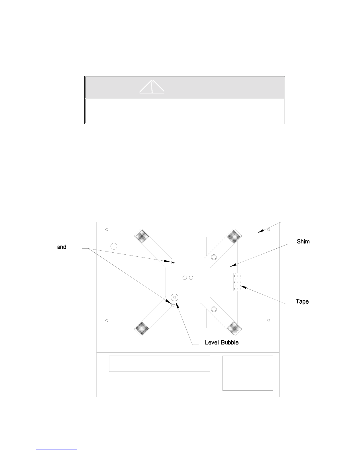
4.1.1. Unpacking Instructions for Low Capacity Scale (for 8572-0002, 1002 versions only)
Remove the rubber band securing the 8" X 8" plastic platter to the s ub-platter. G rasp the plas tic platter
by the edges and lift straight up to remove it. The platter is held by hook and loop fasteners in the
corners. Remove the two #8-32 screws and rubber O rings from the top of the sub-platter. Remove the
tape and shim from the top of the right side of the dead- deck . Locate the level bubble indicator located
on the left front of the subplatter. Refer to Figure 4-1. Save all shipping hardware for future use.
4.1.2. Level the Scale Base
Figure 4-1 Low Capacity Shipping Hardware
9
Page 17

Level the scale by turning the adjustable feet on the bottom of the scale bas e until the level indicator is
correct. The feet mus t be adjusted so the scale does not roc k. Carefully tighten the lock nut at each
adjustable foot. Refer to Figure 4-2.
Figure 2 - Level Bubble
4.1.3. Install All Optional KOPs
Install any desired options in the 8572. Refer to the installation instructions included with the optional kit
of parts. Adding any option to the 8572 requires substituting the optional 1.5 A / 12.5 VDC power supply
(*135693 00A) for the standard 0.6 A / 12 VDC power supply (*135156 00A).
4.1.4. Initial Power Up Sequence
Connect AC power to the 8572 and turn on the power switch (located on the right side of the base near
the front). The following sequence of events will then occur:
6
All cursors, data fields, and legends light up and the decimal point then scr olls across the dis plays
from the right-most digit to the left-most digit.
6
The software part number and revision level are then displayed for a few seconds.
an example of the L02 revision powerup display. If a
[tESt ]
message is displayed instead of the
[135629 L02]
software part number then the 8572 is in the factory test mode. The test mode is entered by
powering up the 8572 with the setup switch turned on and is for factory setup use only. To exit the
test mode: power down the 8572, slide the setup switch to the rear of the enclosure, and power up
the 8572. Refer to Section 4.2. for setup switch location and description.
6
During power up the Logic PCB tests all memory devices and establishes com munication with the
load cell and any optional PCB's that are enabled in setup. Error m ess ages are displayed if any of
the memory tests are failed or if the load cell or optional PCB does not respond.
[E3]
If an
error is displayed then the setup mem ory is corrupt. Access the setup as descr ibed in
Section 4.2. and verify 8572 programming and calibration.
If any other error messages are displayed during the power up sequence refer to Sec tion 7.1. for
error code explanations and recommendations.
6
The last step of the power up sequence involves capturing zero on the gross scale if auto zero
capture or tare interlocks are enabled in setup. If the weight on the gross scale is within the auto
zero capture range (±2% or ±20% of programm ed scale capacity as selected in s etup), zero will be
automatically captured by the 8572 and sample and gross scale selection will be as selected in
setup step
If the weight reading is outside of the zero capture range, the prim ary display shows
[18]
.
[ E E E]
indicate that the weight indication is greater than the auto zero capture range. The primary display
shows
[-E E E]
to indicate that the weight indication is less than the auto zero capture range.
is
to
4.2. PROGRAMMING PROCEDURE
The SETUP mode perm its access to the programm ing and calibration parameters. To enter the SETUP
mode on the 8572, remove the platter ( on scales with the 11" by 14" platform) or rem ove the plastic cover
10
Page 18
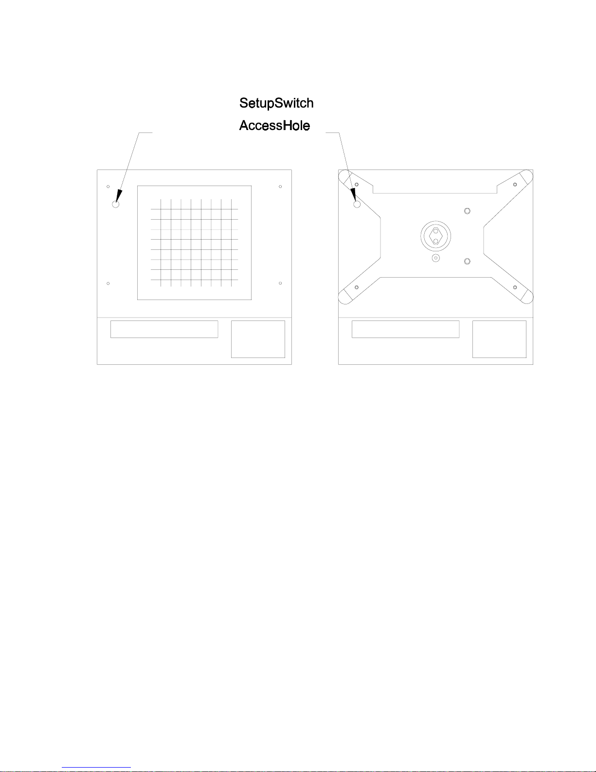
plug (on scales with the 8" square platter) and locate the setup s witch access hole. Refer to Figure 4-3.
Slide the setup switch toward the front of the scale using a pointed, non-conductive object. Do not us e an
object that could be easily dropped into the unit.
Low Capacity Versions Higher Capacity Versions
Figure 4-3 Setup Switch Access Hole
After the setup switch is actuated, the 8572 displays
[-- ]
. The 8572 is now in the setup mode and ready to be
programmed.
The following keys are redefined to perform the function specified when in the setup mode.
ENTER
- Press this key to terminate a data entry for a specific step or accept the displayed value and
advance to the next setup parameter.
ZERO
CLEAR
- Press this key to back-up to the previous step.
- Press this key to clear the display, when the 8572 is prompting for data entry, and permit a new
value to be entered.
1
- Press this key to indicate a
0
- Press this key to indicate a NO response and advances to the next setup selection.
YES
response and advances to the next setup selection.
11
Page 19

4.3. SETUP QUICK REFERENCE
NOTE: The following chart pertains to the
(135629 LO2)
prompt displayed after powerup. Recommended default selections are shown in
[10] ACCESS CALIBRATION GROUP
[11] Weight Units 0 = lb units, no display legend
legend
[12] Linearity Compensation
[13] Remote Scale Selec tion
[15A] Internal Scale Capacity
[16A] Internal Scale Increment Size
[17A] Access Internal Scale Calibration
[14] DigiTOL J-box Shift Adjust
[15B] Remote Scale Capacity
[16B] Remote Scale Increment Size
[17B] Calibrate Remote Scale
[18] Power up Scale Select
1 = lb units and display
2 = kg
3 = g
4 = oz
5 = toz
6 = t
7 = dwt
0 = Disabled
1 = Enabled
0 = Disabled
1 = Single DLC
2 = DigiTOL® J-Box
3 = Analog Input
0 = Sample 1, Gross 1
1 = Sample 1, Gross 2
2 = Sample 2, Gross 1
3 = Sample 2, Gross 2
[20] ACCESS ZERO, MOTION, FILTERING GROUP
[21] Internal Scale AZM 0 = Disabled
[22] Remote Scale AZM 0 = Disabled
[23] Powerup Zero Capture 0 = Disabled
[24] Pushbutton Zero 0 = Disabled
[25] Motion Detect W i ndow 0 = Motion Detect Disabled
[26] Scale 1 Display Filter 0 = Disabled
[27] Scale 2 Display Filter 0 = Disabled
1 = Enabled
1 = Enabled
1 = 2% Scale Capacity
2 = 20% Scale Capacity
1 = Enabled
1 = 0.5 Increment
2 = 1 Increment
1 = Light
2 = Medium
3 = Heavy
1 = Light
2 = Medium
3 = Heavy
revision software. The so f tware r evision is the s ec ond
Italics
.
[28] Enhanced APW Repeat.
0 = Disabled
1 = Enabled
[30] ACCESS TARE GROUP
[31] Gross Scale Tare 0 = Tare Disabled
Tare
[32] Sample Scale Tare 0 = Tare Disabled
[33] Tare Interlock
[34] Auto Clear Tare
1 = Pushbutton Tare
2 = Pushbutton/Keyboard
1 = Pushbutton Tare
0 = Disabled
1 = Enabled
0 = Disabled
1 = Enabled
[40] ACCESS ACCUMULATOR GROUP
[41] Transaction Accum ul ator 0 = Acc umulation Disabled
[42] Auto Clear Accum ul ator
1 = Accumulate Piece Count
2 = Accumulate Gross Weight
3 = Accumulate Net Weight
0 = Disable
1 = Autoclear After Print
[50] ACCESS COUNTING GROUP
[51] APW or Piec e/Unit Weight 0 = Pieces per Unit Weight
[52] Include Sample
[53] Sample Mode and Size
[54] Sample Enhancement 0 = Disabled
[55] Minimum Sampl e Range
[56] Auto Sample Acceptance 0 = Manual Sample Accept
[57] Order Mode Select
[58] Auto Clear APW
[59] Piece Count Auto Ranging
1 = Average Piece Weight
0 = Disabled
1 = Enabled
0 = Variable Sample (10)
1 = Fixed Sample
1 = Enabled
0.02%
1 = Auto Sample Accept
0 = Independent
1 = ID, Tare, APW
2 = ID, Tare, Sample
0 = Disabled
1 = Enabled
0 = Disabled
1 = Enabled
Note: Recommended def aul t selections are shown in
4.3. SETUP QUICK REFERENCE CONTINUED
12
Italics
.
Page 20

[60] DISPLAY CONFIGURATION GROUP
[61] Recall Percent of Ac curacy 0 = Disabled
[62] Power Up Auxiliary Display 0 = Blank
[63] Count Descriptor 0 = None
[64] Cursor Assignment
[65] Decimal Point
[66] ID Enable 0 = Disabled
[67] ID Auto Clear
[68] Consecutive Numbering 0 = Disabled
[69] Test Mode
1 = Enabled
1 = APW
2 = CN
3 = % Acc
1 = "PCS"
2 = "*"
0 = Period Decimal Point
1 = Comma Decimal Point
1 = Enabled
0 = Disabled
1 = Enabled
1 = Enabled
[70] SERIAL I/O GROUP
[77] Print Net Wei ght Expanded
[78] Print Count Expanded
[79] Repeat Print
[81] Auto Print
[82] Option I/O Port Mode
[83] Option I/O Port Parity
[84] Option I/O Port Checksum
[85] Option I/O Port Baud Rate
[86] Option I/O Port Stop Bit
[90] INTERNATIONAL GROUP
[91] Analog Verify
0 = Disabled
1 = Enabled
0 = Disabled
1 = Enabled
0 = Disabled
1 = Enabled
0 = Disabled
1 = Enabled
0 = Disabled
1 = Bar Code Input
2 = Not Used
0 = Space
1 = Odd
2 = Even
0 = Disabled
1 = Enabled
9600
1
0 = Disabled
1 = Enabled
[71] Printer Port Parity 0 = Space
[72] Printer Port Checksum
[73] Printer Port Baud Rate
[74] Print Format 0 = Single Line
[75] Print Fields
[76] Print ID Expanded
1 = Odd
2 = Even
0 = Disabled
1 = Enabled
9600
1 = Multiple Line
02145
0 = Gross Weight
1 = Tare Weight
2 = Net Weight
3 = Displayed Weight
4 = APW or PCS/WGT
5 = Count
6 = Sample Size
7 = ID
8 = Acc Total
9 = Blank Field/New Line
0 = Disabled
1 = Enabled
Note: Recommended def aul t selections are shown in
[92] Bracketed W ei ght Printing
[93] Hand Entered Tare Symbol
[94] ASCII Remote Input
[95] Scale # Display Mode
[96] Order Dependant Prompts 0 = Cursors
[97] Printed Count Legend 0 = None
[98] Examine Individual Load Cell Weights
[99] Reset Default Parameters
Italics
.
0 = Disabled
1 = Enabled
0 = "TRH"
1 = "PT"
0 = Disabled
1 = Enabled
0 = Gross/Sample Selection
1 = Indicates Acti ve S cale
1 = Text
1 = "PCS"
2 = "*"
3 = "STUECK"
0 = Retain Current Setup
1 = US Default Setup
2 = Export Default Setup
13
Page 21
4.4. CALIBRATION GROUP PROGRAMMING
FROM THIS POINT FORWARD
[X.X ]
WILL SHOW THE DISPLAYED PROMPT AND
THE INDENTED PARAGRAPHS WILL EXPLAIN THE SETUP STEPS FUNCTION AND
SELECTIONS. TO EXIT THE SETUP MODE, SLIDE THE SETUP SWITCH TO THE
REAR OF THE SCALE ANY TIME THE DISPLAY IS SHOWING
[--]
.
[10] CALIBRATION GROUP
With
[--]
on the display press the 1 key and then the 0 key. The display will then show
[11 X]
.
[11 1] CALIBRATION UNITS
Select the units to be used for the primar y display and the test weight type used during span adjust and
calibration. Enter selection using the numeric keys on the keyboard.
Number Display Weight Legend Calibration Weights
0
1
2
3
4
5
6
7
None
lb
kg
g
oz
toz
t
dwt
lb
lb
kg
g
oz
troy oz
metric tons
penny-weight
[12 0] LINEARITY COMPENSATION
The 8572 provides a calibration procedure to allow compensation of nonlinearities in the weighing
performance of the scale base. T his procedure is not nor mally required and is provided for use only when
the normal calibration procedure does not result in a linear response from the scale.
0
- Linearity compensation is disabled.
1
- Two step linearity compensation is enabled.
NOTE:
When us ing linearity compensation, test weights of one half scale capacity and full sc ale capacity mus t
be used. If less than full capacity is used, linearity compensation is not performed.
[13 0] REMOTE SCALE SELECTION
Selects type of remote scale base in use. Enter selection using the numeric keys on the keyboard.
Number Scale 2 Selection
0
1
2
3
Note:
If a remote scale bas e is not selec ted
Model 2157 (digital j-box) is not selected
None
Single DigiTOL® Load Cell
Model 2157 Floor Scale (digital j-box)
Analog Load Cell
[13 0]
[13 2]
, then steps
, then step
[14], [15b], [16b]
[14]
is skipped.
, and
[17b]
are skipped. If
14
Page 22
4.4.1. Internal Scale Setup and Calibration
[15A] [100] INTERNAL SCALE CAPACITY
Enter a valid capacity for the internal scale using the numeric keys on the keyboard followed by the
ENTER
NOTE
key. Refer to step
: The scale capacity entered must be large enough to use at least 35% of full load c ell capacity. If a
capacity selection is entered that is too sm all for the load cell, the 8572 will display an
[11]
and Tables 4-1 and 4-2 for valid capacity selections.
[E36]
error during
calibration. Refer to Table 4-1 for minimum valid scale capacities for a specific load cell capacity.
[16A] [0.02] INTERNAL SCALE INCREMENT SIZE
Press the 0 key to display the next selection. Press the
ENTER
increment size. Refer to Tables 4-1 and 4-2 for valid increment selection.
8572
Default Capacities Minimum Capacities Load
Factory
Number
lb kg lb kg
8572-0002, 1002
8572-0003, 1003
8572-0004, 1004
8572-0005, 1005
8572-0006, 1006
5 X 0.001
10 X 0.002
25 X 0.005
50 X 0.01
100 X 0.02
2.5 X 0.0005
5 X 0.001
10 X 0.002
25 X 0.005
50 X 0.01
3
6
12
25
50
Table 4-1 Default and Minimum Internal Scale Builds
Increment
Scale Capacity (Total Number of Displayed Increments)
Size
3000 4000 5000 6000 10000 20000 25000 40000 50000
0.0001
0.0002
0.0005
0.001
0.002
0.005
N.A.
N.A.
1.5
3
6
15
N.A.
N.A.
2
4
8
20
N.A.
1
N.A.
5
10
25
N.A.
N.A.
3
6
12
30
1
2
5
10
20
50
2
4
10
20
40
100
or 1 key to accept the displayed
Cell
Capacity
1.5
3
6
12
25
N.A.
5
N.A.
25
50
125
N.A.
N.A.
20
N.A.
N.A.
N.A.
3.75 kg
7.5 kg
15 kg
30 kg
60 kg
5
10
25
50
N.A.
N.A.
0.01
0.02
0.05
0.1
0.2
0.5
1
2
5
10
20
30
60
150
300
600
1500
3000
6000
15000
30000
60000
40
80
200
400
800
2000
4000
8000
20000
40000
N.A.
50
100
250
500
1000
2500
5000
10000
25000
50000
N.A.
60
120
300
600
1200
3000
6000
12000
30000
60000
N.A.
100
200
500
1000
2000
5000
10000
20000
50000
N.A.
N.A.
Table 4-2 Valid Scale Builds
(N.A.) Not Applicable
15
200
400
1000
2000
4000
10000
20000
40000
N.A.
N.A.
N.A.
250
500
1250
2500
5000
12500
25000
50000
N.A.
N.A.
N.A.
N.A.
N.A.
N.A.
N.A.
N.A.
N.A.
N.A.
N.A.
N.A.
N.A.
N.A.
N.A.
1000
N.A.
N.A.
N.A.
N.A.
N.A.
N.A.
N.A.
N.A.
N.A.
Page 23

[17A] CALIBRATE SCALE 1
Press the 1 key to calibrate scale 1, or press the 0 key to advance to skip calibrate the next
programming step.
[E SCL] EMPTY SCALE
Empty the scale platter then press the
[CAL 01]
as a zero reading is recorded. The display then shows
ENTER key.
The display then counts down from
[Av]
while the analog verify reading is
[CAL 16]
to
recorded.
The span calibration sequence is next. Scale calibration will follow one of two following procedures
depending on how linearity compensation is programmed.
If linearity compensation is disabled, setup step
If linearity compensation is enabled, setup step
[12 0]
, then Section 4.4.1.2. will be skipped.
[12 1]
, then Section 4.4.1.1. will be skipped.
4.4.1.1. Internal Scale Span Calibration (With Linearity Compensation Off)
[Add Ld] ADD LOAD
Place test weights as close to 50% of full scale capacity as possible on the center of the scale
platter and press the
disabled, setup step
Enter the value of the test weights using the numeric keys followed by the
NOTE:
The test weight value used should be as close to the programm ed scale capacity as pos sible,
ENTER
[12 0]
key. This prompt will only occur if linear ity compensation has been
.
ENTER
key.
but in any case no less than 50% of scale capacity. In no case may the test weight used be larger than
the scale capacity programmed in setup step
[15A]
.
The display then counts down from
[CAL 16]
[CAL 09]
to
. The 8572 compares the programmed
scale capacity with the number of raw counts output by the load cell. If the load cell is not sending
sufficient counts for the scale capacity entered, the 8572 sends the load cell new T1 calibration
parameters and attempts to increase the number of counts from the load cell.
If the load cell cannot output enough counts for the pr ogramm ed scale capacity an
be displayed. This error means the s cale capacity entered in setup step
[15A]
[E36]
is too small for the
load cell and must be increased, or that the load cell is not operating properly.
If the 8572 receives enough counts from the load cell the count down will continue from
[CAL 01].
Increasing the number of counts out of the load c ell will require an additional
[CAL 09]
step to complete the calibration.
[E SCL] EMPTY SCALE (Occurs only if new calibration data is sent to load cell)
Empty the scale platter then press the
[CAL 01]
to
as a zero reading is recorded. The display then shows
ENTER key.
The display then counts down from
[Av]
while the analog verify
reading is recorded. If linearity compensation is disabled the 8572 then skips to section 4.3.1.4.
error will
to
[E SCL]
[CAL 16]
16
Page 24

4.4.1.2. Internal Scale Span Calibration (With Linearity Compensation On)
[Add FL] ADD FULL CAPACITY LOAD
Place test weights as close to 100% of f ull scale capacity as possible on the center of the scale
platter and press the
enabled, setup step
ENTER
[12 1]
key. This prompt will only occur if linear ity compensation has been
.
Enter the value of the test weights using the numeric keys followed by the
NOTE
: Linearity compensation calibration requires test weights as close to 100% and 50% of scale
capacity as possible. Calibration with test weights other than 100% of capacity at
capacity at
The display counts down from
[Add L0]
can result in weighing errors.
[CAL 16]
[CAL 09]
to
. The 8572 compares the pr ogrammed s cale
ENTER
[Add FL]
key.
or 50% of
capacity with the number of raw counts output by the load cell. If the load cell is not sending
sufficient counts for the scale capacity entered, the 8572 sends the load cell new T1 calibration
parameters and attempts to increase the number of counts from the load cell.
If the load cell cannot output enough counts for the pr ogramm ed scale capacity an
[E36]
be displayed. This error means the s cale capacity entered in setup step 15A is too small for the
load cell and must be increased, or that the load cell is not operating properly.
If the 8572 receives enough counts from the load cell the count down will continue from
[CAL 01].
Increasing the number of counts out of the load c ell will require an additional
[CAL 09]
step to complete the calibration.
[Add LO] ADD HALF CAPACITY LOAD
Place test weights as close to 50% of full scale capacity as possible on the center of the scale
platter and press the
Enter the value of the test weights using the numeric keys followed by the
ENTER
key.
ENTER
key.
error will
to
[E SCL]
The 8572 then counts down from
[CAL16]
[CAL 01]
to
.
[E SCL] EMPTY SCALE (Occurs only if new calibration data is sent to load cell)
Empty the scale platter then press the
[CAL 01]
as a zero reading is recorded.
ENTER
key. The display then counts down from
[Av]
is displayed as analog verify reading is recorded.
4.4.1.3. Internal Scale Calibration Complete
[CAL1 d] SCALE 1 CALIBRATION DONE
The display shows
[CAL1 d]
for two seconds and then will advance to one of three poss ible steps
depending on how setup step 13 is programmed:
NOTE
: If remote scale bas e is disabled (step
group and advance to the
[13 3]
or
) the 8572 will skip setup step
[--]
display. If a Single DLC or analog remote base is selected, (step
[14]
[13 0]
), the 8572 will skip all further steps in the 10's
and advance to step
[15b]
.
[CAL 16]
[13 1]
to
17
Page 25

4.4.2. Remote Scale Shift Adjust
[14] SHIFT ADJUST (Model 2157 Floor Scale (digital j-box), setup step [13 2])
This step accesses shif t er r or c ompensation for the Model 2157 or the DigiTO L® Power Module. Pres s
the 1 key to enter the shift adjust step or press the 0 key to skip this step and advance to step
NOTE
: The digital j-box must be connected to four load cells when used with the 8572.
[E SCL] EMPTY SCALE
[15b]
.
Empty the scale platter then press the
[SHF 01]
as a zero reading is recorded.
ENTER
key. The display then counts down from
[SHF 16]
[CELL 01] CELL TO BE ADJUSTED?
The display will then show
directly over cell 01 and press the
The display will then show
[CELL 01]
ENTER
[CELL 02]
where 01 is the first cell to be shif t adjusted. Place a weight
key. The display will count down from
[SHF 16]
to
.
Repeat this procedure for cells 2, 3 and 4. Place the weight directly over each load cell in turn and
press the print key. Press the
ZERO
key to back up to the previous load cell if necessary.
24
1J-Box 3
Figure 4-4 Model 2157 Load Cell Location
4.4.3. Remote Scale Setup and Calibration
to
[SHF 01]
.
[15b] [XXX] REMOTE SCALE CAPACITY
Enter a valid capacity for the remote scale using the numeric keys followed by the
[11]
step
, the remote scale base data plate and technical manual, and Table 4-2 for valid capacity
ENTER
key. Refer to
selection.
NOTE
: The scale capacity entered must be large enough to use at least 35% of full load c ell capacity. If a
capacity selection is entered that is too small, the scale will display an
[E36]
error during calibration.
[16b] [0.01] REMOTE SCALE INCREMENT SIZE
Press the 0 key to display the next selection. Press the
ENTER
or 1 key to accept the displayed
increment size. Refer to Table 4-2 for valid increment size selection.
[17b] CALIBRATE SCALE 2
Press the 1 key to calibrate the remote scale, or pres s the 0 key to advance to the next programm ing
step.
[E SCL] EMPTY SCALE
18
Page 26

Empty the scale platter then press the
[CAL 01]
as a zero reading is recorded. The display then shows
ENTER
key. The display then counts down from
[Av]
while the analog verify reading is
[CAL 16]
to
recorded.
The span calibration sequence is next. Scale calibration will follow one of two following procedures
depending on how linearity compensation is programmed.
If linearity compensation is disabled, setup step
If linearity compensation is enabled, setup step
[12 0]
, then Section 4.4.3.2. will be skipped.
[12 1]
, then Section 4.4.3.1. will be skipped.
4.4.3.1. Remote Scale Span Calibration (Linearity Compensation Off)
[Add Ld] ADD LOAD
Place test weights as close to full sc ale capacity as possible on the center of the scale platter and
press the
setup step
Enter the value of the test weights using the numeric keys followed by the
NOTE
: The test weight value used should be as close to the programmed sc ale capacity as possible,
ENTER
[12 0]
key. This prompt will only occur if linearity compensation has been disabled,
.
ENTER
key.
but in any case no less than 10% of scale capacity. In no case may the test weight used be larger than
the scale capacity programmed in setup step
The display then counts down from
[15b]
[CAL 16]
.
[CAL 09]
to
. The 8572 compares the programmed
scale capacity with the number of raw counts output by the load cell. If the load cell is not sending
sufficient counts for the scale capacity entered, the 8572 sends the load cell new T1 calibration
parameters and attempts to increase the number of counts from the load cell.
If the load cell cannot output enough counts for the pr ogramm ed scale capacity an
[E36]
error will
be displayed. This error means the s cale capacity entered in setup step 15A is too small for the
load cell and must be increased, or that the load cell is not operating properly.
If sufficient counts are received fr om the load cell the c ount down continues fr om
01].
Increasing the number of counts out of the load c ell will require an additional
[CAL 09]
[E SCL]
complete the calibration.
[E SCL] EMPTY SCALE (Occurs only if new calibration data is sent to load cell)
Empty the scale platter then press the
[CAL 01]
to
as a zero reading is recorded.
linearity compensation is disabled the 8572 will skip to section 4.3.2.4.
ENTER key.
[Av]
is displayed as analog verify reading is recorded. If
The display then counts down from
[CAL2 d]
.
4.4.3.2. Remote Scale Span Calibration (Linearity Compensation On)
[Add FL] ADD FULL CAPACITY LOAD
Place test weights as close to 100% of f ull scale capacity as possible on the center of the scale
platter and press the
enabled, setup step
Enter the value of the test weights using the numeric keys followed by the
ENTER
[12 1]
key. This prompt will only occur if linear ity compensation has been
.
ENTER
key.
[CAL
to
step to
[CAL 16]
19
Page 27

NOTE
: Linearity compensation calibration requires test weights as close to 100% and 50% of scale
capacity as possible. Calibration with test weights other than 100% of capacity at
capacity at
[Add L0]
can result in weighing errors.
[Add FL]
or 50% of
The display counts down from
[CAL 16]
[CAL 09]
to
. The 8572 compares the pr ogrammed s cale
capacity with the number of raw counts output by the load cell. If the load cell is not sending
sufficient counts for the scale capacity entered, the 8572 sends the load cell new T1 calibration
parameters and attempts to increase the number of counts from the load cell.
If the load cell cannot output enough counts for the pr ogramm ed scale capacity an
[E36]
be displayed. This error means the s cale capacity entered in setup step 15A is too small for the
load cell and must be increased, or that the load cell is not operating properly.
If the 8572 receives enough counts from the load cell the count down will continue from
[CAL 01].
Increasing the number of counts out of the load c ell will require an additional
[CAL 09]
step to complete the calibration.
[Add LO] ADD HALF CAPACITY LOAD
Place test weights as close to 50% of full scale capacity as possible on the center of the scale
platter and press the
enabled, setup step
Enter the value of the test weights using the numeric keys followed by the
NOTE
: The test weight value used must be as close to the 50% programmed scale capacity as
ENTER
[12 1]
key. This prompt will only occur if linear ity compensation has been
.
ENTER
key.
possible.
The 8572 then counts down from
[CAL16]
[CAL 01]
to
.
error will
to
[E SCL]
[E SCL] EMPTY SCALE (Occurs only if new calibration data is sent to load cell)
Empty the scale platter then press the
[CAL 01]
to
as a zero reading is recorded.
ENTER
[Av]
key. The display then counts down from
is displayed as analog verify reading is recorded.
4.4.3.3. Remote Scale calibration Done
[CAL2 d] REMOTE SCALE CALIBRATION DONE
The display shows
[CAL2 d]
for two seconds and then the 8572 will display
[-- ]
.
[18 0] POWER UP SCALE SELECT MODE
This step selects the def ault power up scale select ion for which base is us ed for sampling and which base
is used for counting (gross).
Enter selection using the numeric keys on the keyboard.
Number Sample Scale Counting (Gross) Scale
0
1
2
3
Internal (Scale 1)
Internal (Scale 1)
External (Scale 2)
External (Scale 2)
Internal (Scale 1)
External (Scale 2)
Internal (Scale 1)
External (Scale 2)
[CAL 16]
4.5. ZERO, MOTION, AND FILTERING GROUP PROGRAMMING
20
Page 28

[20] ZERO, MOTION, AND FILTERING GROUP
With
[--]
on the display press the 2 key then the 0 key. The display will then show
[21 X]
.
[21 1] INTERNAL SCALE AUTO ZERO MAINTENANCE (AZM)
This selection controls AZM for the internal scale. Auto zero maintenance is a f eature that maintains the
displayed zero in the center of the zero increment. It will correct for zero drift up to a 0.1 increm ent per
second, over a range of ± 2% of s c ale capac ity if the tare interloc k is enabled, s etup s tep
of ± 20% of scale capacity if the tare interlock is disabled, setup step
0 -
Internal scale AZM is disabled.
1 -
Internal scale AZM is enabled, as controlled by tare interlock.
[33 0]
.
[33 1]
, or a range
[22 1] REMOTE SCALE AUTO ZERO MAINTENANCE (AZM)
This selection controls AZM for the remote scale, otherwise this step is identical to setup step 21.
0 -
Remote Scale AZM disabled.
1 -
Remote Scale AZM enabled.
[23 1] POWERUP ZERO CAPTURE
This s tep programs the range for autom atic zero capture when power is applied to the 8572. If powerup
zero capture is enabled, and the scale is outside of the zero capture range, the display will show
weights above the zero capture range), or
[-E E E]
(for weights below the zero capture range), on the
[E E E]
(for
display until zero is manually captured.
Enter selection using the numeric keys on the keyboard.
Number Powerup Zero Capture Range
0
1
2
Disabled
±2% of Scale Capacity
±20% of Scale Capacity
[24 1] PUSHBUTTON ZERO RANGE
A zero key is provided to rezero the scale over a range of ± 2% of scale capacity if the tare interlock is
enabled, setup step
[33 0]
. The scale must be in the gross mode and in a no motion condition to allow zeroing.
0 -
Pushbutton zero is disabled.
1 -
Pushbutton zero is enabled, as controlled by tare interlock.
[33 1]
, or a range of ± 20% of scale c apac ity if the tare interlock is disabled, setup step
[25 1] MOTION DETECTION
21
Page 29

The 8572 includes a weight in motion detector which requires three suc cessive weight readings within the
selected range of ± 0.5 increm ent or ± 1 increment for a "no motion" signal. The motion detector signal
inhibits AZM, ZERO, TARE, PRINT and SAMPLE functions. If the tare interlock is disabled, motion will
blank the lb/kg cursors.
Enter selection using the numeric keys on the keyboard.
Number Motion Detect Window
0
1
2
Disabled
±0.5 Increment
±1 Increment
[26 1] SCALE 1 DISPLAY FILTER
The 8572 has a low pass multi-pole digital f ilter that is s electable f or various environm ental conditions . T he
display rate is slowed slightly as heavier filtering is selected.
Enter selection using the numeric keys on the keyboard.
Number Display Filter
0
1
2
3
Disabled
Light
Medium
Heavy
[27 1] REMOTE SCALE DISPLAY FILTER
This step controls the filter for scale 2, otherwise this step is identical to the scale 1 filter.
Enter selection using the numeric keys on the keyboard.
Number Display Filter
0
1
2
3
Disabled
Light
Medium
Heavy
[28 0] ENHANCED APW REPEATABILITY
Enabling this function helps to ensure m axim um APW accu racy and repeatability and helps to m inim ize the
effects of vibration. When sampling, the APW calculation will take approximately two seconds.
0
- Enhanced APW Repeatability Disabled
1
- Enhanced APW Repeatability Enabled
4.6. TARE GROUP PROGRAMMING
22
Page 30

[30] TARE GROUP
With
[--]
on the display press the 3 key then the 0 key. The display will then show
[31 X]
.
[31 2] GROSS SCALE TARE ENABLE
The 8572 allows pushbutton tare, manual keyboard tare, or both with the gross s c ale. T he s c ale must be in
a "no motion" condition before a tare can be taken, subject to tare interlock restrictions.
Enter selection using the numeric keys on the keyboard.
Number Tare Mode
0
1
2
Pushbutton & Keyboard Tare
Tare Disabled
Pushbutton Tare Only
[32 1] SAMPLE SCALE TARE ENABLE
The 8572 allows pushbutton tare only with the sample scale. The s cale m ust be in a "no m otion" condition
before a tare can be taken, subject to tare interlock restrictions.
0 -
Sample Scale Pushbutton Tare Disabled
1 -
Sample Scale Pushbutton Tare Enabled
[33 0] TARE INTERLOCK
Tare interlocks include the following functions: Tare weights can be c leared only at gross zero. Tare can
only be entered in the gross mode. Keyboard tare can only be entered in the gross mode. Previous tare
values must be cleared bef ore a new tare value can be entered. Multiple tares ar e not possible. T he lb/kg
cursors will not blank with motion. Tare interlock also limits the range over which pushbutton zero and AZM
will operate to ± 2% of scale capacity. Pushbutton zero and AZM will operate over a range of ± 20% of
scale capacity if tare interlock is disabled.
0 -
Tare Interlock Disabled
1 -
Tare Interlock Enabled
[34 0] AUTO CLEAR TA RE
The 8572 can automatically clear tare when the scale returns to zero after settling to a no m otion condition
at least ten increments above net zero. The scale must r eturn to within one positive increment of zero or
any negative gross weight to be considered to have to returned to zero. The scale must be in the count
mode for auto clear tare to occur.
0 -
Auto Clear Tare Disabled
1 -
Auto Clear Tare Enabled
4.7. ACCUMULATOR GROUP PROGRAMMING
[40] ACCUMULATOR GROUP
23
Page 31

With
[--]
on the display press the 4 key then the 0 key. The display will then show
[41 X]
.
[41 1] TRANSACTION ACCUMULATOR
A single register accumulator is provided to accum ulate piec e count, gros s weight or net weight as selec ted
below. Accumulation is perfor med by pressing the
PRINT
key while in the count mode, by use of the host
port command, or indirectly by the auto print function. When an accumulation is performed the auxiliary
display will blank, the TOTAL cursor will flash and then return to the previous recalled display. The
accumulation register can store up to seven digits of total piece count or nine digits of total weight.
The accumulated total c an be displayed by pressing the
RECALL
key. The TOTAL curs or will turn when
the auxiliary display is showing accumulated total to indicate this is the accumulator total.
Enter selection using the numeric keys on the keyboard.
Number Accumulator Mode
0
1
2
3
Disabled
Count
Gross Weight
Net Weight
[42 0] AUTO CLEAR ACCUMULATOR AFTER TOTAL PRINT
The 8572 accumulator c an be programmed to autom atically clear after the
PRINT
key is pressed with the
total count in the auxiliary display. If this function is disabled the accumulator must be m anually cleared by
pressing the 0 key followed by the
ENTER
key, while the accumulated total is displayed by means of the
recall function.
0 -
Disable Auto Clear Accumulator After Total Print
1 -
Enable Auto Clear Accumulator After Total Print
24
Page 32

4.8. SAMPLE GROUP PROGRAMMING
[50] SAMPLE GROUP
With
[--]
on the display press the 5 key then the 0 key. The display will then show
[51 X]
.
[51 1] APW OR PIECES PER UNIT WEIGHT
0 -
If the piece weight is to be entered as pieces per unit of weight.
1 -
If the piece weight is to be entered as a decimal average piece weight.
[52 0] INCLUDE SAMPLE
Include sample is provided to autom atically add the sam ple size to the total count and s am ple weight to the
gross and net weight of a transaction. If include sample is enabled the s ample pieces must not be added to
the gross scale or the total count and weight will be off by the amount of the sample.
0 -
Include Sample is Disabled
1 -
Include Sample is Enabled
[53 0] [53 10] FIXED SAMPLE, SAMPLE SIZE SELECTION
The 8572 operates with fixed or variable sam ple sizes. Press the 0 key to select variable sample size or
press the 1 key to select fixed sam ple s ize mode. Af ter the s ampling mode is s elec ted the 8572 will dis play
the fixed or the default variable sam ple s ize. Press the 0 key for the next default sample s ize or press the
key to accept the default sample size. Options for sample size are 5, 10, 20, 50 or 100.
0 -
Variable Sample Size
1 -
Fixed Sample Size
1
[54 1] SAMPLE ENHANCEMENT
Sample enhancement is provided to allow the 8572 to recalc ulate the APW on the basis of a larger s ample
size each time more pieces are added to the scale.
NOTE
: This function is disabled when the 8572 is in the dual scale counting mode or if a
minimum sample percentage of 0.00% is selected in setup step
0 -
Sample Enhancement is disabled
1 -
Sample Enhancement is Enabled
[55]
.
[55 0.02] MINIMUM SAMPLE RANGE
Selects the percentage of scale capacity that must be reached before an average piece weight can be
calculated and a count sequence initiated. The available percentages are 0.00%, 0.02%, 0.05% and
0.10%. Sample enhancement is dis abled at 0.00%. If the sample pieces placed on the s cale weigh less
than the selected minimum sample range, the 8572 will prompt the operator to place additional sample
pieces on the sample scale, (
0 -
Select New Minimum Sample Percentage
1 -
Accept Displayed Minimum Sample Percentage
[Add XXX]
where XXX = additional sample pieces required).
[56 1] AUTO SAMPLE ACCEPTANCE
25
Page 33

This function selects how additional sample pieces are accepted to reach the minimum sample
requirement. Manual sample accept requires the operator to press the
Enter
after placing additional parts
on the sample scale. Auto sample accept only requires the operator to place the requested number of
sample pieces on the sample scale and the APW is then automatically calculated.
0 -
Manual Sample Accept
1 -
Auto Sample Accept
[57 0] ORDER MODE SELECT
The order dependant mode prom pts the operator through the c ounting sequence. T he
ENTER
key ma y be
used to terminate an ID, TARE, or APW /SAMPLE entry. The or der independent mode requires that each
function be terminated with the respective function key.
Number Order Mode Select
0
1
2
Independent
ID, TARE, APW
ID, TARE, SAMPLE
[58 0] APW AUTO CLEAR
The 8572 can automatically clear the average piece weight when the scale returns to within one positive
increment above zero or less, after settling to a no motion condition ten increments above net or gross zero.
0 -
APW Auto Clear Disable
1 -
APW Auto Clear Enable
[59 0] PIECE COUNT AUTO-RANGING
Auto-ranging rounds off the displayed piece count in increm ents of 1, 2, 5, 10 or higher as nec essary when
the APW for a given part is smaller than the internal resolution of the scale.
0 -
Auto-Ranging Disabled
1 -
Auto-Ranging Enabled
4.9. DISPLAY GROUP PROGRAMMING
[60] DISPLAY GROUP
26
Page 34

[--]
With
on the display press the 6 key then the 0 key. The display will then show
[61 1] RECALL PERCENT OF ACCURACY
0 -
To disable the recall of Percentage of Accuracy.
1 -
To enable the recall of Percentage of Accuracy after a count has been made.
[62 1] POWER UP AUXILIARY DISPLAY
Enter selection using the numeric keys on the keyboard.
Number Powerup Auxiliary Display
[61 X]
.
0
1
2
3
Accumulated Total
Average Piece Weight
Consecutive Number
Percentage of Accuracy
[63 1] DISPLAYED COUNT DESCRIPTION
The 8572 can be programmed to display a "*", "PCS" or no legend when in the count mode.
Enter selection using the numeric keys on the keyboard.
Number Count Legend
0
1
2
None
PCS
*
[64 0] [64 --] DISPLAY CURSOR ASSIGNMENT
Display cursor assignment is provided to permit the display cursors to be redefined for specialized
application that use custom silk screened display bezels. All other application should use the standard
default cursor assignments.
0 -
To Skip Display Cursor Assignment
1 -
To Access Display Cursor Assignment
When the disp lay shows
keyboard. The display then shows
display location, refer to Figure 4-5 for cursor location. After each cursor ass ignment the display returns to
[64 --]
. Repeat this operation until all the cursors are assigned.
[64 --]
, enter the desired cursor func tion selection using the numeric k eys on the
[64XX Y]
, where XX is the cursor function and Y is the current cursor
27
Page 35

Figure 4-5 Programmable Cursor Locations
NOTE
: Cursor assignment is limited by the following restrictions.
6
A maximum of 8 cursors can be assigned and cursor numbers can not be duplicates.
Entering a 0 for a cursor location will cancel that cursor assignment.
6
If the TARE cursor (09) is assigned then the DIG ITAL T ARE curs or (10) and the PUSHBUTT ON T ARE
cursor (11) will be locked out and can not be assigned.
6
If the DIGITAL TARE curs or (10) or the PUSHBUTTON T ARE (11) is assigned then the T ARE cursor
(9) will be locked out and can not be assigned.
6
Cursor function selection 00 terminates the cursor assignment sequence.
6
Cursor function selection 13 resets all cursor assignments back to the default assignments and
terminates the cursor assignment sequence.
6
Cursor function 14 cancels all cursor assignments.
Cursor/Function Number Default Location Cursor Description / Function
00
01
02
03
04
05
06
07
08
09
10
11
12
13
14
[65 0] DECIMAL POINT (Period or Comma)
0 -
Period Decimal Point
N.U.
7
1
5
0
6
0
2
3
4
N.U.
8
N.U.
N.U.
N.U.
(N.U.) Not Used
Exit Cursor Assignment
Average Piece Weight
Sample
Percentage of Accuracy
ID
Consecutive Numbering
Gross Weight
Net Weight
Zero
Tare
Digital Tare
Pushbutton Tare
Accumulator Total
Reset to Default Cursor Assignments
Cancel all Cursor Assignments
28
Page 36

1 -
Comma Decimal Point
[66 1] ID ENABLE
The 8572 can accept up to 16 digits of alpha- numeric ID f rom the optional bar c ode input or host port. Up
to 16 digits of numeric ID can be entered from the 8572 keyboard. This ID can be printed.
0 -
ID Disabled
1 -
ID Enabled
[67 0] ID AUTO CLEAR
The 8572 can automatically clear ID when the scale returns to within one positive increment above zero or
less, after settling to a no motion condition ten increments above net or gross zero.
0 -
ID Auto Clear Disable
1 -
ID Auto Clear Enable
[68 1] CONSECUTIVE NUMBERING
0 -
Consecutive Numbering Disabled
1 -
Consecutive Numbering Enabled, indicates the number of accumulations performed.
[69 0] TEST MODE (Expanded Weight Display/Keyboard Test)
When the tes t mode is enabled the primary display shows the internal increm ents (displayed increments
times 10) and the auxiliary display shows the raw counts from the load c ell or analog interface card. The
SCALE SELECT
key toggles the display between scale 1 and scale 2. The
ZERO
key zeros the internal
increments display. The . (period) key toggles between the current and default T1 c alibration values in the
single DLC scale bases.
The keyboard test is accessed by pressing the
RECALL
key. The primary display shows
[PrS 00]
. At this time
press each of the keys on the keyboard in turn starting with the . (period) key, lower left. As each key is pressed
the display updates to indicate the coordinates of the next key to be pressed. Refer to Figure 4-6. After the
keyboard test is finished the 8572 returns to the expanded weight display.
30 31 32 33 34
20 21 22 23 24
10 11 12 13 14
00 01 02 03 04
Figure 4-6 Keyboard Test Response Codes
29
Page 37
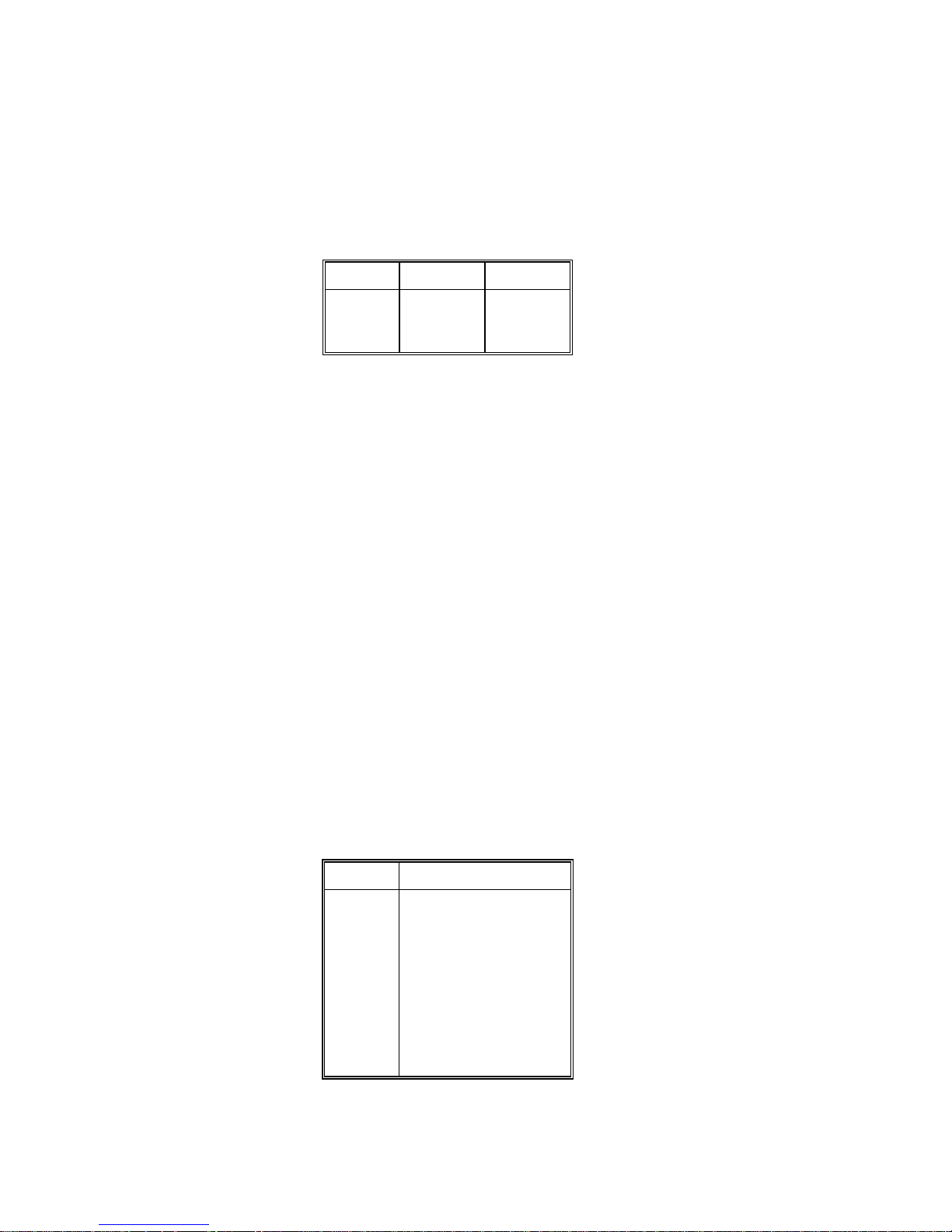
4.10. SERIAL I/O GROUP PROGRAMMING
[70] SERIAL I/O GROUP
With
[--]
on the display press the 7 key then the 0 key. The display will then show
[71 X]
.
[71 2] PRINTER PORT PARITY
Enter selection using the numeric keys on the keyboard.
Number Data Bits Parity Bit
0
1
2
8
7
7
None
Odd
Even
[72 0] PRINTER PORT CHECKSUM
Checksum is defined as the 2's c omplem ent of the 7 low order bits of the binary sum of all charac ters on a
line, preceding the checksum.
0 -
Checksum is Disabled
1 -
Checksum is Enabled
[73] [9600] PRINTER PORT BAUD RATE
Select baud rate from 300, 1200, 2400, 4800, to 9600 baud.
0 -
To advance to the next Baud Rate Selection
1 -
To accept the displayed Baud Rate selection
[74 1] MULTI LINE PRINT FORMAT
0 -
Print all data on one line
1 -
Each field of data is printed on a separate line
[75] [02145 ] [2145 ] PRINT FIELDS
Up to seven different fields of data can be selec ted for output, but the 8572 can only display 6 entries for this
setup step. Entries 1 - 6 are displayed first then entries 2 - 7 are displayed. Entries 1 - 6 are displayed for data
entry. Data fields can be repeated if desired. The blank field selection is either a blank line or 7 spaces
depending on single line/multi line print selection.
Number Data Field
0
1
2
3
4
5
6
7
8
9
Gross Weight
Tare Weight
Net Weight
Displayed Weight
APW or PCS/Weight
Piece Count
Sample Size
ID
Accumulator Total
Blank Field
[76 0] PRINT ID EXPANDED
30
Page 38

ASCII Shift out <SO> and shift in <SI> characters are inserted in the printer output to enable expanded
(double width) print. Expanded printing is usable with the 8806 and 8860 printers only.
0 -
Print ID Normal
1 -
Print ID Expanded
[77 0] PRINT NET WEIGHT EXPANDED
0 -
Print Net Weight Normal
1 -
Print Net Weight Expanded
[78 0] PRINT COUNT EXPANDED
0 -
Print Count Normal
1 -
Print Count Expanded
[79 0] REPEAT PRINT
If repeat print is disabled the scale m ust s ettle to zero between transac tions bef ore the pr int request will be
acted upon. If the repeat print function is enabled, successive pressings of the
PRINT
key without changing
the weight on the scale will result in an exact duplicate of the previous print.
0 -
Repeat Print Disable
1 -
Repeat Print Enable
[81 0] AUTO PRINT
0 -
Auto Print is Disabled
1 -
The 8572 will automatically transmit the selec ted print fields when a piece c ount of m ore than 50 is
displayed with no motion.
[82 0] OPTION I/O PORT MODE
Selects operational mode for the option I/O port. W hen selected for use as a bar code por t the 8572 can
scan ID, tare and APW weight.
Enter selection using the numeric keys on the keyboard.
Number Option I/O Port Mode
0
1
2
Disabled
Bar Code Input
Reserved for future use
NOTE: ID can be entered into the 8572 only in the order dependant mode, setup step [57 1] or [57 2].
NOTE
: The 2 of 5 interleaved bar code form at does not support a decimal point and can only be used for ID
entry with the 8572.
NOTE
: Setup Steps 83 through 84 are skipped if the option I/O port is disabled or pr ogrammed for bar code
input,
[82 0]
or
[82 1]
.
[83 0] OPTION I/O PORT PARITY
31
Page 39

Enter selection using the numeric keys on the keyboard.
Number Data Bits Parity Bit
0
1
2
8
7
7
None
Odd
Even
[84 0] OPTION I/O PORT CHECKSUM
Checksum is defined as the 2's c omplem ent of the 7 low order bits of the binary sum of all charac ters on a
line, preceding the checksum.
0 -
Checksum is Disabled
1 -
Checksum is Enabled
[85] [9600] OPTION I/O PORT BAUD RA TE
The 8572 option port can communicate at 300, 1200, 2400, 4800, or 9600 baud.
0 -
To advance to the next Baud Rate Selection
1 -
To accept the displayed Baud Rate selection
[86 1] OPTION I/O PORT STOP BITS
1 -
One Stop Bit
2 -
Two Stop Bits
4.10. INTERNATIONAL GROUP PROGRAMMING
[90] INTERNATIONAL GROUP
With
[--]
on the display press the 9 key then the 0 key. The display will then show
[91 X]
.
[91 0] ANALOG VERIFY
Analog verify feature will perform a chec k on the load cell or analog interface car d every four hours when
enabled. If the analog verify test is failed for either the internal or rem ote scale, the 8572 will disable that
scale base. If the 8572 has a rem ote scale base installed, the 8572 can operate with the s cale base that
did not fail the analog verify test. Press the
CLEAR
key to reset the error code and operate the 8572 in the
single scale mode. If the 8572 does not have a r emote base installed, then the 8572 m ust be powered
down and then powered up to clear the error.
0 -
Analog Verify is Disabled
1 -
Analog Verify is Enabled
[92 0] BRACKETED WEIGHT PRINTING
This selection will enclose in brackets < >, all weight data that is actually measured as oppos ed to m anually
entered data such as tare or APW weights enter ed by means of the keyboard, bar code scanning, or the
host port.
0 -
Bracketed Weight Printing is Disabled
1 -
Bracketed Weight Printing is Enabled
[93 0] HAND ENTERED TARE WEIGHT SYMBOL
32
Page 40

The 8572 will either print "TRH" or "PT" after a tare weight that was manually entered by means of the
keyboard, bar code scanning or the host port.
0 -
Print "TRH" after Manually Entered Tare Weight
1 -
Print "PT" after manually Entered Tare Weight
[94 0] ASCII REMOTE INPUT
When this function is enabled the 8572 will respond to single ASCII characters input into the printer port.
0 -
ASCII Remote Input is Disabled
1 -
ASCII Remote Input is Enabled
[95 0] SCALE NUMBER DISPLAY MODE
Select scale number displays operating mode. Mode 0 will indicate gross/sample s cale assignm ent as well
as which is the active scale. Mode 1 indicates active scale only.
0 -
Indicate gross/sample scale assignment and flash the active scale's number.
1 -
Use the scale number displays to indicate the active scale only.
[96 1] TEXT PROMPTS, ORDER DEPENDANT MODE
When the 8572 is programmed for order dependant m ode, s etup step
[57 1]
or
[57 2]
, then the operator is
prompted through the count sequence. The pr ompts can be abbreviated text m essages: id? f or ID, tr? for
tare, APu? for APW, or SPL? for sample, or the 8572 can prompt the operator by means of the cursors.
0 -
Use abbreviated text messages to prompt the operator, order dependant mode.
1
- Use the cursors to prompt the operator in the order dependant mode.
[97 1] PRINTED PIECE COUNT SYMBOL
Select the legend to print after the piece count: "PCS", "*", or "STUECK" (German).
Enter selection using the numeric keys on the keyboard.
Number Piece Count Printed Legend
0
1
2
3
No Symbol Printed
PCS
*
STUECK
[98 0] EXAMINE INDIVIDUAL LOAD CELL WEIGHTS (2157 Floor Scale, digital j-box only)
This selection is provided as an aide to trouble shooting. Pr ess the 0 key to skip to the
the 1 key to view load cell weights. The 8572 will then dis play:
one through four. The display will then show:
counts and Y is cell number. Press the
ENTER
[XXXXXX CELL Y]
key to advance to the next load cell. If the 8572 is currently
[CELL]
Enter the cell number to be viewed,
XXXXXX is the cell output in raw
[--]
prompt. Press
displaying load cell number four then the display will advance to load cell number one. Press the
key to exit to the
[--]
prompt.
[99 0] RESET SETUP PARAMETERS TO DEFAULT VALUES
CLEAR
33
Page 41

This step will reset
reprogrammed to the default values.
ALL SETUP STEPS
except the scale calibration group. All other setup steps will be
0
- Skip to the
1
- Reset parameters to U.S.A. default values.
2
- Reset parameters to General Export default values.
If 1 or 2 is selected the display will then show:
[SurE]
Flashing
0
- To abort resetting parameters to default values.
1
- To reset all setup steps to default values.
If 1 is pressed
Switch U.S.A.
11 1 2
12 0 0
13 0 0
18 0 0
21 1 1
22 1 1
23 1 1
24 1 1
25 1 1
26 1 1
27 1 1
28 0 1
31 2 2
32 1 1
33 0 0
34 0 0
[--]
[Ld EEr]
prompt without resetting parameters.
is displayed while setup memory is being loaded with selected default values.
Export
Switch U.S.A.
61 1 0
62 1 1
63 1 1
65 0 0
66 1 1
67 0 0
68 1 1
69 0 0
71 2 2
72 0 0
73 9600 2400
74 1 1
75 02145 02145
76 0 0
77 0 0
78 0 0
79 0 1
Export
41 1 1
42 0 1
51 1 1
52 0 0
53 10 10
54 1 1
55 0.02 0.02
56 1 1
57 0 0
58 0 0
59 0 0
5. OPERATING INSTRUCTIONS
5.1. DISPLAY FORMAT AND LEGENDS
81 0 0
82 0 0
83 0 0
84 0 0
85 9600 9600
86 1 1
91 0 0
92 0 0
93 0 1
94 0 0
95 0 0
96 1 0
97 1 3
98 0 0
34
Page 42
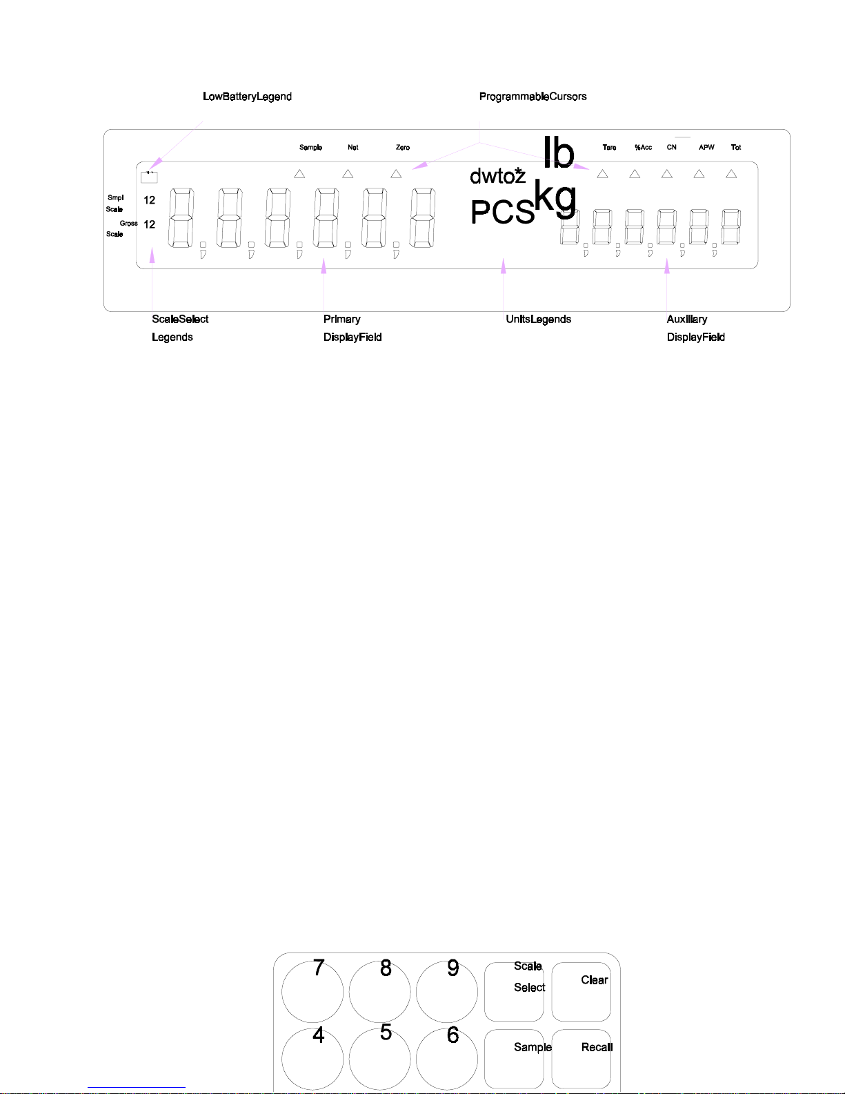
Figure 5-1 LCD Display
The 8572 uses a liquid crystal display that is divided into two six digit display fields. Programmable cu rsors
indicate what data is being displayed or what data is to be entered. An explanation of the function of each
cursor follows:
Smpl
Scale
Gross
Scale
Sample
Net
Zero
Tare
%Acc
CN
APW
Tot
- The sample scale selection is indicated by a (1) for the internal scale or a (2) for the remote
scale base. A flashing scale number indic ates the scale that is currently displayed in the primary
display field.
- The gross scale selection is indicated by a (1) for the internal scale or a (2) for the remote
scale base. A flashing scale number indic ates the scale that is currently displayed in the primary
display field.
- Indicates that the sample function is in use in the order dependent mode.
- Indicates that the primary or auxiliary field is displaying net weight.
- Indicates that the active scale is at gross zero.
- Indicates that a tare is to be entered in the order dependent mode.
- Indicates that the auxiliary field is displaying the percentage of counting accuracy.
- Indicates that the auxiliary field is displaying consecutive numbering.
- Indicates that the auxiliary field is displaying the APW (average piece weight).
- Indicates that the auxiliary field is displaying the accumulator total.
5.2. KEYBOARD OPERATION
35
Page 43

Figure 6 - Keyboard Layout
Decimal Point (.)
& Numeric Digits
Yes/1
No/0
Clear
- Used in setup procedure. Enables the displayed selection in setup.
- Used in setup procedure. Disables the displayed selection shown in setup.
- To clear incorrectly entered data, press the
exit the data entry mode. Press the
APW, and ID.
Print
- Press the
motion is present, the print request is s tored and acted upon when motion ceas es. A print
operation adds the current value to the accumulator and increments the consecutive
number (if enabled).
Scale Select
- Press the
combination. The 8572 can count and sample on either the internal (scale 1) or optional
external (scale 2) base. Dual scale applications normally use the lower capacity scale base
for sampling and the higher capacity scale base for counting.
Zero
- Press the
weight reading on the scale base or if the gross weight reading is m ore than ±20% of scale
capacity from the gross zero weight referenc e r ecor ded dur ing calibr ation ( limited to ±2% of
scale capacity if tare interlocks enabled).
- For entry of ID, APW, sample size, and tare weights.
Clear
key once. Press the
Clear
key twice to exit the count mode and clear tare,
PRINT
key with no motion on the scale to transmit data out the printer por t. If
Scale Select
ZERO
key to capture a new zero reference. Zero capture is disabled if the
key to change to the next available gross and sample sc ale
CLEAR
key twice to
The order operating mode (setup step
keys are used. Refer to Section 5.2.1. for or der independent mode definitions for these keys. Refer to
Section 5.2.2. for order dependent mode definitions for these keys.
Recall
- Recalls the next data field to be displayed in the auxiliary field. Each time the
pressed, the auxiliary display recalls the next data field. Data fields are recalled as
described in Table 5-1.
Data Recalled Order Independent Mode Order Dependent Mode
[57]
) determines how the
36
APW, Enter, Recall, Sample
Recall
, and
Tare
key is
Page 44

Gross Weight
Net Weight
Tare Weight
APW
Percentage of Accuracy
Consecutive Numbering
Accumulator Total
No tare entered.
Tare entered.
Tare entered.
No restriction.
% accuracy recall enabled.
CN enabled.
Accumulation enabled.
Table 5-1 Recall Key operation
Count mode, no tare entered.
Count mode, tare entered.
Count mode, tare entered.
Count mode.
Count mode, % accuracy recall enabled.
Count mode, CN enabled.
Count mode, Accumulation enabled.
Note: Order dependant mode must be in the count m ode to use the recall f unction.
before the recalled accumulator total if the accumulator has overflowed.
5.2.1. Order Independent Mode Key Definitions
APW
Enter
Sample
- Press the
- Not used.
- Press the
APW
key to terminate entry of an average piece weight.
Sample
key to terminate entry of a sample size value. Pressing the
by itself will cause a sample operation to occur using the fixed or default sample size.
5.2.2. Order Dependent Mode Key Definitions
APW
Enter
- Press the
prompting for sam ple. The
piece weight value, same as
- Press the
When the 8572 is prompting for ID, the
When the 8572 is prompting for tare weight, press the
APW
key to switch to the average piece weight entry mode, when the 8572 is
APW
key can also be used to terminate entry of an average
Enter
key.
ENTER
key to terminate values entered and to advance to the next step.
Enter
key can be pressed to skip ID entry.
Enter
key to take an autotare
(autotare takes the weight currently on the scale as a tare weight, if the scale is at gross
zero then tare is not taken).
[
//////
]
is displayed
Sample
key
When the 8572 is pr ompting for sample, pr es s the
Enter
key to use default or fixed sample
size.
Sample
Tare
- Press the
to the sampling mode. T he
quantity or to sample using the default or fixed sample size, same as
- Press the
Sample
Tare
key when the 8572 is prompting for an average piece weight, to s witch
Sample
key can also be used to terminate entry of a sample
key to terminate a tare weight entry, same as
Enter
Enter
key.
key.
5.3. PUSHBUTTON ZERO
The 8572 provides a pushbutton zero function to recapture gross zero, if necessary. Zero can only be
captured for the scale base c urrently displayed in the primary display field and only when the 8572 is in the
gross weight mode. Zero capture is disabled if the weight reading on the scale base is uns table or if the
gross weight reading is more than ±20% of scale capacity from the gross zero weight reference recorded
during calibration (limited to ±2% of scale capacity if tare interlocks enabled).
37
Page 45

5.3.1. Zeroing the Gross Scale
To zero the gross scale, remove all parts from the gr os s s c ale platter and pr es s the
Zero
key. If zero is
not captured, verify that the 8572 is in the gross weight mode, that the scale platter is unobstr ucted and
that the displayed weight on the scale is within ±20% of scale capacity of gross zero (±2% of scale
capacity if tare interlocks enabled). If zero still can't be captured, refer to Section 7.2. for
troubleshooting advice.
5.3.2. Zeroing the Sample Scale
The sample scale is zeroed in one of two ways depending on operating mode selection.
Order Dependent Mode
Press the
Enter
key until the auxiliary display shows
[SPL?]
or
[APv?]
or the sample or APW
cursors indicate that the sample scale is currently displayed.
Remove all parts from the sam ple scale platter and press the
Zero
key. If zero is not captured,
verify that the 8572 is in the gross weight mode, that the scale platter is unobs tructed and that the
displayed weight on the scale is within ±20% of scale capacity of gross zero ( ±2% of scale capac ity
if tare interlocks enabled). If zero still can't be captured, refer to Sec tion 7.2. for troubleshooting
advice.
Order Independent Mode
Press the
Remove all parts from the sam ple scale platter and press the
Enter
key until the sample scale is displayed in the primary display field.
Zero
key. If zero is not captured,
verify that the 8572 is in the gross weight mode, that the scale platter is unobs tructed and that the
displayed weight on the scale is within ±20% of scale capacity of gross zero ( ±2% of scale capac ity
if tare interlocks enabled). If zero still can't be captured, refer to Sec tion 7.2. for troubleshooting
advice.
Press the
Enter
key until the gross scale is displayed in the primary display field.
5.4. COUNTING OPERATION
The 8572 provides two modes of counting operation: Order dependent m ode with either sam pling or APW
entry, and order independent mode.
ID, tare or APW values can be scanned in using the optional bar code input, inst ead of manually entering
the data the 8572 is prompting for.
38
Page 46

00.000
If ID is enabled, the operator is always prompted to enter an ID firs t. The 8572 accepts up to 16 digits of
numeric ID from the keyboard or up to 16 alphanumeric characters from the optional bar code input.
5.4.1. Order Dependent Counting Modes
In the order dependent mode the 8572 prompts the operator step by step through the counting
procedure, beginning with ID entry, then a tare entry, and finally a sampling procedure or APW entry.
The order dependent mode is eas ier for an oper ator to learn than the order independent m ode and the
step by step prompting by the 8572 helps ensure that required steps are not skipped.
The
average piece weight that requires a new sample procedure be performed each time the parts are
counted or when the average piece weight is not known.
The
have consistent, known average piece weights. Another application that uses the APW entry mode
involves the counting of very light parts that require an extremely large sample size to accurately
calculate the APW . In this case the APW is calc ulated with a large sample size, this APW is recorded
and used whenever this particular part is counted. Recorded APW values should be recalculated
periodically with new parts to prevent counting errors that could occ ur if the parts average piece weight
had changed since the last APW calculation.
id?
order dependent sampling mode
order dependent APW entry mode
is typically used when counting parts with an inconsistent
is typically used in applications where the parts to be counted
lb
5.4.1.1. Single Scale, Count Up Mode (Empty Container)
Tare Entry
lb
00.000
Place the empty container on the gross scale and press the
weight of container followed by the
Sample Entry
tr?
Enter
or
Enter
Tare
key if manual tare entry mode is desired.
or
Tare
key. Enter the tare
lb
00.000
Place sample pieces in the container , enter the sample quantity, then press the
key. If fixed sample size operation has been selected then place the fixed number of sample
pieces in the container and press the
Or APW entry
SPL?
Enter
or
Sample
key.
Enter
or
Sample
00.000
If the average piece weight (APW) of the part to be counted is known, the APW can be entered
instead of sampling. Enter the APW using the numeric keys then press the
lb
APu?
39
Enter
or
APW
key.
Page 47

Count Display
157
The 8572 is now in the count mode. Place the res t of the par ts to be c ounted in the c ontainer . T he
number of pieces in the container is now displayed in the primary display field. The data selected
for recall is displayed in the auxiliary display field. Press the
print a label.
5.4.1.2. Dual Scale, Count Up Mode (Empty Container)
Tare Entry
PCS
.0015
PRINT
key to accumulate data and
lb
00.000
Place the empty container on the gross scale and press the
weight of container followed by the
Sample Entry
tr?
Enter
or
Enter
Tare
key if manual tare entry mode is desired.
or
Tare
key. Enter the tare
lb
00.000
Place sample pieces on the sample scale, enter the sample quantity, then press the
Sample
sample pieces on the sample scale and press the
SPL?
key. If fixed sample size operation has been selected then place the fixed number of
Enter
or
Sample
key.
Enter
or
Or APW entry
lb
00.000
If the average piece weight (APW) of the part to be counted is known, the APW can be entered
instead of sampling. Enter the APW using the numeric keys followed by the
Count Display
157
The 8572 is now in the count mode. Place the rest of the par ts to be counted on the gross sc ale.
The number of pieces in the container are now displayed in the primary display field. The data
selected for recall is displayed in the auxiliary display field.
If "Include Sample" is enabled, the count displayed includes the sample pieces on the sample
scale. Do not place the sample pieces in the container until after you press the
accumulate data and print a label. If inc lude sample is disabled then return the sample pieces to
the full container and press the
5.4.1.3. Single Scale, Count Up Mode (Full Container)
Tare Entry
PCS
APu?
.0015
PRINT
Enter
key to accumulate data and print a label.
or
APW
PRINT
lb
00.000
tr?
key.
key to
40
Page 48

Place the full container on the gross s cale and enter the known tare weight of the container using
the numeric keys followed by the
Sample Entry
Enter
or
Tare
key.
00.000
Remove sample pieces from the container, enter the sample quantity, then press the
Sample
pieces from the container and press the
Or APW entry
SPL?
key. If fixed sample size operation is selected then r emove the fixed number of sam ple
Enter
or
Sample
key.
lb
lb
00.000
If the average piece weight (APW) of the part to be counted is known, the APW can be entered
instead of sampling if the display is prompting f or APW entry. Press the
sample mode to APW entry mode. Enter the APW using the numeric keys followed by the
APW
key.
Count Display
157
The number of pieces in the container are now displayed in the primary display field. The data
selected for recall is displayed in the auxiliary display field. Press the
data and print a label.
PCS
APu?
.0015
APW
PRINT
key to switch from
key to accumulate
Enter
Enter
or
or
5.4.1.4. Dual Scale Count Up Mode (Full Container)
Tare Entry
lb
00.000
Place the full container on the gross s cale and enter the known tare weight of the container using
the numeric keys followed by the
Sample Entry
tr?
Enter
or
Tare
key.
lb
00.000
Place sample pieces on the sample scale, enter the sample quantity, then press the
Sample
pieces on the sample scale and press the
Or APW entry
SPL?
key. If fixed sample size operation is selected then place the fixed number of sample
Enter
or
Sample
key.
lb
00.000
APu?
Enter
or
41
Page 49

If the average piece weight (APW) of the part to be counted is known, the APW can be entered
instead of sampling if the display is prompting f or APW entry. Press the
sample mode to APW entry mode. Enter the APW using the numeric keys followed by the
APW
key.
Count Display
APW
key to switch from
Enter
or
157
The number of pieces in the container are now displayed in the primary display field. The data
selected for recall is displayed in the auxiliary display field. If include sample is enabled the count
displayed includes the sample quantity, press the
If include sample is disabled then return the sample pieces to the full container and press the
PRINT
5.4.1.5. Single Scale Count Down Mode (Out of a Full Container)
Tare Entry
PCS
key to accumulate data and print a label.
.0015
PRINT
key to accumulate data and print a label.
lb
00.000
Place the full container on the scale and press the
Sample Entry
tr?
Enter
or
Tare
key.
lb
00.000
Remove sample pieces from the container, enter the sample quantity, then press the
Sample
pieces from the container and press the
SPL?
key. If fixed sample size operation is selected then r emove the fixed number of sam ple
Enter
or
Sample
key.
Enter
or
Or APW entry
lb
00.000
If the average piece weight (APW) of the part to be counted is known, the APW can be entered
instead of sampling if the display is prompting f or APW entry. Press the
sample mode to APW entry mode. Enter the APW using the numeric keys followed by the
APW
Count Display
10
The 8572 is now ready to count. Remove parts desired f rom the container. The pieces r emoved
from the container are displayed in the primary display field. The data selected for recall is
displayed in the auxiliary display field. Press the
5.4.2. Order Independent Counting Mode
If the user does not prefer the 8572's self prompting, step by step, dependant mode of oper ation, the
independent mode can be enabled during setup. The independent mode of operation allows the user to
key.
PCS
APu?
.0015
APW
key to switch from
PRINT
key to accumulate data and print a label.
Enter
or
42
Page 50

input data or accumulate transaction data in sequences independent from others. The independent
mode of operation is ideal f or applications where counting or weighing oper ations are not completed in
the same manner from one transaction to the next. Transaction data can be randomly input in any
order, permitting flexibility of operation.
In the independent mode of operation, all data input is terminated by pressing the function key
associated with that function:
APW, Sample
, or
Tare
.
If the bar code option is installed in the 8572, ID, tare or APW can be entered at any time by scanning in
the appropriate data.
Note: The order dependent mode MUST be used if keyboard entered ID is required. The only way to
enter ID into the 8572 in the order independent mode is by using the optional bar code input.
5.4.2.1. Single or Dual Scale, Count Up Mode (Empty Container)
Place an empty container on the gross scale and press the
Tare
key. If manual tare entry mode is
desired in place of auto tare, enter the tare weight of container on the gross scale by using the
numeric keys followed by the
Place sample pieces on the sample scale and press the
selected add sample pieces equal to the default sample size and press the
Tare
key.
Sample
key. If fixed sample size is
Sample
key.
If the average piece weight (APW) of the part to be counted is known, the APW can be entered
instead of sampling. Enter the APW using the numeric keys followed by the
now in the count mode. Place the parts to be counted on the gross sc ale. Press the
APW
key. The 8572 is
PRINT
accumulate data and print a label.
5.4.2.2. Single Scale, Count Up Mode (Full Container)
Place the full container on the gross s cale and enter the known tare weight of the container using
the numeric keys followed by the
Remove sample pieces from the container and press the
Tare
key.
Sample
key. If fixed sample size is
selected remove sample pieces equal to the def ault sample size from the container and press the
Sample
key.
If the average piece weight (APW) of the part to be counted is known, the APW can be entered
instead of sampling. Enter the APW using the numeric keys followed by the
Enter
key.
The 8572 will now display the count of pieces in the container. If "Include Sample" is enabled, the
count displayed includes the sample quantity. Press the
PRINT
key to accumulate data and print a
label. If "Include Sample" is disabled then replace the sample pieces to the container and pr ess the
PRINT
key to accumulate data and print a label.
key to
5.4.2.3. Dual Scale Count Up Mode (Full Container)
Place full container on the gross s cale and enter the known tare weight of the container using the
numeric keys followed by the
Tare
key.
43
Page 51

Add sample pieces to the sam ple scale. If f ixed sample size is select ed add sample pieces equal
to the default sample size press the
Sample
key.
If the average piece weight (APW) of the part to be counted is known, the APW can be entered
instead of sampling. Enter the APW using the numeric keys followed by the
Enter
key.
The 8572 will now display the count of pieces in the container. If "Include Sample" is enabled, the
count displayed includes the sample quantity. Press the
PRINT
key to accumulate data and print a
label. If "Include Sample" is disabled then return the sam ple pieces to the container and press the
PRINT
key to accumulate data and print a label.
5.4.2.4. Single Scale Count Down Mode (Out of a Full Container)
Place full container on the scale, press the
Tare
key.
Remove the sample pieces from the full container. Enter sample size using the numeric keys
followed by the
sample size programmed in setup and press the
Sample
key. If fixed sample size desired remove sample pieces equal to fixed
Sample
key.
If the average piece weight (APW) of the part to be counted is known, the APW can be entered
instead of sampling. Enter the APW using the numeric keys followed by the
Enter
key.
The 8572 is now ready to count. Remove the parts to be counted from the container. Press the
PRINT
key to accumulate data and print a label.
5.5. SAMPLE ENHANCEMENT AND COUNTING WEIGHT RANGE PARAMETERS
The 8572 provides sample enhancement for single scale mode operation, to permit accurate counting of
light weight or inconsistent parts without having to hand count a large sample size. When sample
enhancement is used the APW is recalculated as more parts are placed on the scale. Sample
enhancement requires at least one extra step in the normal count procedure.
To use sample enhanc ement, proceed through the normal count procedure until the 8572 is in the count
mode, displaying the sample pieces. At this time, place additional pieces, roughly equivalent to but not
more than the sample quantity already on the scale. The 8572 will then automatically recalculate the APW
on the basis of the larger sample s ize. There is no need to count the extra sample piec es added during
sample enhancement, j ust be sure to roughly double the number of piec es on the scale each tim e sam ple
enhancement is used. Sample enhancement can be repeated as many times as needed (up to 4% of scale
capacity), until the sample size required to accurately count a specific part is reached.
Four distinct zones of counting exist in relation to the weight on the platter. These zones are as follows:
Zone 1
: Below Minimum APW Computation Range
44
Page 52

The weight placed on the sample sc ale is below the minimum APW c omputation (0.02% of f ull scale
capacity). If sampling is attempted the primary display will show
[LO SPL]
and no sampling will occur.
Zone 2
: 0.02% of Scale Capacity to Minimum Sample Range
The weight placed on the sample scale is between 0.02% of full scale capacity and the minimum
sample range selected in setup. If s ampling is attem pted the primar y display will show
[+ n]
where "n"
is the maximum number of pieces that can be added to the sample scale on the basis of the APW
calculated by the original sample. If m ore than this number of pieces is added to the s ample scale then
[/ / / / / / ]
will be displayed on the primary display until the correct number of pieces is plac ed on
the sample scale.
A manual sample acceptance mode is also available which requir es the exac t number of samp le pieces
be added and the
[Sample]
(order independent mode) key be pressed. This results in the most
accurate APW calculation.
Zone 3
: Minimum Sample Range to 4% of Sample Scale Capacity, May Enhance Counting Zone
From the minim um sample range to 4% of sam ple scale capacity, the 8572 is operating in the count
mode. Printing and accumulation can be performed as desired. The APW will be enhanced
throughout this range unless too many pieces are added to the sam ple sc ale or weight is added to the
gross scale. If the operator adds m ore pieces than can be reliably counted on the basis of the ear lier
sample, the primary display will show
[/ / / / / / ]
for two seconds then return to showing count data.
If the operator wishes to continue APW enhancement, pieces must be r emoved from the scale until a
change in sample weight no longer results in the
[/ / / / / / ]
display. APW enhancem ent will then
occur.
If the operator ignores the
[/ / / / / / ]
display and adds more pieces, prints or accumulates, no
further APW enhancement is possible for the current tr ansaction. Once the counting weight exceeds
4% of full scale capacity, APW enhancement is discontinued.
Note
: Zone 3 does not exist if average piece weight enhancement is disabled.
Zone 4
: Normal Counting Zone, 4% of Scale Capacity to Full Scale Capacity
Once the weight applied to the scale exceeds 4% of f ull scale capacity, APW enhancem ent is disabled
and the displayed APW will no longer change.
45
Page 53

- For Your Notes -
46
Page 54

6. INPUT AND OUTPUT CONNECTORS AND INTERFACING
6.1. PRINTER INTERFACE SPECIFICATIONS
The 8572 is capable of transmitting and receiving RS-232 voltage level ASCII characters. The device
connected to the printer port must be a true RS-232 device. This is r equired because the voltage fr om the
device's receive line is used to power the 8572's transmit line.
The 8572 transmits data suitable f or use with Toledo Scale printer Models 8806, 8842, and 8860. W hen
the print function is actuated by means of the
control command, the 8572 will output a mess age according to setup program ming. Scale m otion holds a
printout until the scale sees "no motion". Printing is disabled when the scale is under gross zero, over
capacity, or in expanded weight mode.
6.1.1. Data Format
The data output is in a 10 bit ASCII format: 1 start bit, 7 data bits, 1 parity bit (selectable to even, odd, or
always a 0), and 1 stop bit. The baud rate can be set from 300, 1200, 2400, 4800, to 9600 baud.
Checksum is provided to ensure data integrity. Checksum is defined as the 2's complem ent of the 7
low order bits of the binary sum of all characters on a line, preceding the checksum.
The 8572 is capable of transmitting data in either a single line or multi line format. T he data fields to be
printed are selected in setup. From one to seven f ields of data will be printed in the order deter mined in
setup. Fields may be repeated as many times as desired. Refer to T able 6-1 f or single line f orm at and
to Table 6-2 for multi line scale format.
Print
key, auto print function or receipt of a rem ote ASCII
Data STX DF1 UF1 DF2 UF2 DF3 UF3 DF4 UF4 DF5 UF5 DF6 UF6 DF7 UF7 CR CHK LF
Note A BCBCBCBCBCBCBCDEF
Table 6-1 Single Line Data Format
STX DF1 UF1 CR CHK LF
Data
DF2 UF2 CR CHK LF
DF3 UF3 CR CHK LF
DF4 UF4 CR CHK LF
DF5 UF5 CR CHK LF
DF6 UF6 CR CHK LF
DF7 UF7 CR CHK LF
Notes A B C D E, G F
Table 6-2 Multiple Line Data Format
47
Page 55

DATA FORMAT NOTE(S):
A: <STX> ASCII start of text character, hex value 02. This character can be disabled.
B: <DFX> Numeric component of data field X. Refer to weight field format notes.
C: <UFX> Units component of data field X. Refer to Table 4 for field options.
D: <CR> ASCII carriage return, hex value 0D.
E: <CHK> Checksum character, 2's complement of the 7 low order bits of the binary sum of all
character on a line, preceding the checksum. This character can be disabled.
F: <LF> ASCII Line Feed, hex value 0A.
G: <CHK> The checksum calculation for multiple line data format includes the line feed <LF>
character from the previous line of data.
Note
: All data fields are padded with leading spaces to make fields right justified. Leading zeros of numeric
data fields are suppressed. If the 8572 is progr am m ed to display a comm a in plac e of a dec im al point then
significant leading zeroes are not suppressed.
Note
: If double width printing is enabled, an ASCII <SO> character, hex 0E, will precede the net weight or
gross weight numeric field, (if printing displayed weight and the 8572 is in the gross mode). An ASCII <SI>
character will follow the corresponding Units field.
Note
: If bracketed printing is enabled in setup then any truly measured weight will be preceded by a <
character and followed by a > character.
Weight Field Format Notes:
The sign character is a space < > for positive net weights and a minus <-> for negative net weights.
The weight data field is a seven character ASCII string consisting of six numeric digits plus a dec imal
point. If the decimal point is not used the weight data has a leading s pac e added to pad the total length
of the weight data to 7 characters.
Net weight
Gross or tare weight, (Single Line Format)
Gross or tare weight, (Multi Line Format)
Accumulated Total (Weight)
:<Sign character><Weight data>, total 8 bytes.
:<Weight data>, total 7 bytes.
:<Space><Weight data>, total 8 bytes.
: 9 digits of accumulated weight followed by a * if accumulator has
overflowed, total 10 bytes.
Non Weight Fields Format Notes:
APW
: Seven digits of average piece weight data, with a decimal point.
Sample
Count
Accumulated Total (Count)
: Six digits of sample size data.
: Six digits of piece count data.
: Seven digits of accumulated total piece count followed by a * if
accumulator has overflowed, 8 bytes.
ID
: 16 digits of alphanumeric ID data. Leading zeroes are not suppressed for ID, trailing spaces are
not printed.
48
Page 56

6.1.2. Printer Interconnect
The 8572 requires the 15 ft printer interf ac e cable ( Fac tor y Number 0900-0243) to c onnect to the Model
8806, 8842, and the 8860 Toledo Scale Printers. The 8572 requires the 20 ft printer interfac e cable
(Factory Number 0900-0250) to connect to the 8860 W ashdown Printer. Refer to technical m anuals
TM008806 I00, TM008843 I00, TM/PC008860 I00, and T MWD8860 I00 for information about printer
setup and programming. Refer to Table 6-3 for connector pinout.
8572 J1 8806, 8843,
8860 Desk
Pin Function Pin Pin
2
TxD (RS-232)
3
RxD (RS-232)
7
Ground
Table 6-3 Printer Interfacing Interconnect
Note
: ASCII Remote Input (setup step
8806 or 8860 printer.
6.1.3. ASCII Remote Input
The 8572 will respond to upper case, single ASCII characters transmitted to the 8572 printer port from a
remote device. The ASCII data transmitted into the 8572 must have the sam e baud rate, parity and
data bit formatting the 8572 data output. Remote ASCII input must be enabled, setup step
commands that the 8572 printer port can respond to are:
Character Function and Keyboard Equivalent
C<CR>
H<CR>
P<CR>
R<CR>
T<CR>
Z<CR>
Same as
Clears the accumulator total.
Same as
Transmits the accumulator total.
Same as the
Same as the
CLEAR key,
PRINT
[94]
must be disabled when the 8572 is connected to the Model
key, accumulator is updated if enabled.
TARE
key.
ZERO
key.
3
2
7
resets the scale to the gross mode.
8860
Washdown
C
B
G
[94 1]
. The
6.2. REMOTE SCALE BASE INTERFACING
DO NOT attach an analog load cell to a DigiTOL® scale input or a DigiTOL® load cell to an analog scale input of the
8572 as damage to the load cell or scale input PCB may result.
REMOVE POWER FROM THE SCALE AND WAIT A MINIMUM OF 30 SECONDS BEFORE CONNECTING OR
DISCONNECTING ANY HARNESSES FROM PCB'S OR LOAD CELLS AS DAMAGE MAY RESULT.
The 0.6 A/12 VDC power supply (*135156 00A), MUST be replaced with the optional 1.5 A/12.5 VDC power supply
(*135693 00A) when any optional KOP is installed in the Model 8572.
Table 6-4 Remote ASCII Input Commands
3 CAUTION!
49
Page 57
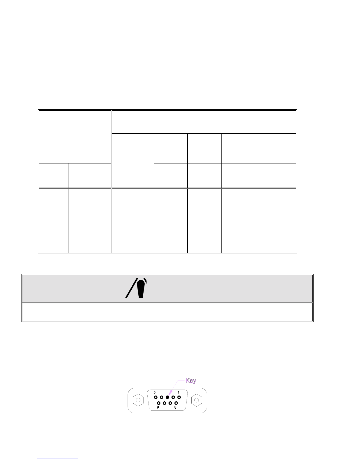
6.2.1. Remote DigiTOL® Scale Base Connection
The 8572 remote DigiTO L® scale base KOP permits the connection of any of the standard DigiTO L®
bench and portable scale bases, Models 1996, 1997, 2096, 2097, 2196 and 2197. T he 8572 remote
DigiTOL® scale base KOP is also compatible with the Model 2157 floor scale (digital j-box).
Single DigiTOL® load cells provide 1 part in 500,000 resolution with nine updates per second. The
digital j-box provides up to 1 part in 280,000 resolution.
Note
: The remote DigiTO L® s c ale KOP, ( Fac tor y Number 0901-0281) , must be installed in the 8572 bef ore
a DigiTOL® scale base can be connected to the 8572. Refer to Table 6-5 for wiring information.
Model 8572
Function
J-2 Pin Color
DigiTOL® Scale Base Connector
1996
2096
2196
Pin
1997
2097
2197
Color
Carbon
Steel TB5
Model 2157
Digital J-Box
Stainless
Steel
Connector
1
2
3
4
5
6
7
8
9
Red
Not Used
Key
White
Green
Yellow
Blue
Black
Not Used
RxD A
Not Used
Not Used
RxD B
+20 VDC
TxD B
Ground
TxD A
Not Used
Table 6-5 DigiTOL® Scale Base Interconnect
1
Not Used
Not Used
Not Used
5
6
7
8
Not Used
Red
Green
Yellow
Blue
Black
3
4
6
2
5
1
4 CAUTION!
THE WHITE WIRE
BASES OR DAMAGE TO THE DIGITOL® LOAD CELL AND SCALE INPUT PCB MAY RESULT!
The DigiTOL® load cell connector mounted on the 8572 I/O connector bracket has a key in pin 3.
Refer to Figure 6-1 for key pin location. This key is installed to insure that an analog scale base cannot
be plugged into this connector. This key pin
with the DigiTOL® Scale KOP has pin 3 removed. If a different connector is used it will be neces s ar y to
remove pin 3 of the m ating connector. To ac complis h this, grab as m uch of the pin as possible with a
pair of needle nose pliers and bend the pin back and forth until it breaks. Mak e sure that all adjacent
pins remain straight.
MUST NOT
BE CONNECTED TO MODEL 1996, 1997, 2096, 2097, 2196 AND 2197
MUST NOT
be removed. The m ating connector included
A
D
E
F
G
H
50
Page 58

Figure 6-1 DigiTOL® Load Cell Connector
6.2.2. Remote Analog Scale Base Connection
The 8572 remote analog base KOP is capable of dr iving up to f our, 350 ohm load cells of either 2 mV/V
or 3 mV/V signal output type. The remote analog sc ale bas e KO P provides 1 par t in 500,000 res olution
with four updates per second.
Note
: The remote Analog scale KOP, (Factory Number 0901-0283) , must be installed in the 8572 before
an analog scale base can be connected to the 8572. Refer to Table 6-for wiring information. T he shield of
the load cell cable connects to structure (chas sis) ground at the scale base, and to the metal shell of the
cable clamp at the 8572.
Load Cell Termination
8572
J3 Pin Function
6 Wire Cable 4 Wire Cable
Jumpers
Wire Color Pin Wire Color
1
2
3
4
5
6
7
8
9
+Excitation
+Sense
Shield
-Sense
-Excitation
Key
+Signal
-Signal
Not Used
White
Yellow
Orange
Red
Blue
Not Used
Green
Black
Not Used
A
D
F
C
E
B
Green
Jumper
Yellow
Jumper
Black
Not used
White
Red
Not Used
S),
S)-
S),
S)-
Table 6-6 Analog Scale Base Interconnection
The analog load cell connector m ounted on the 8572 I/O connec tor brac ket has a key in pin 6. Refer to
Figure 6-2 for key pin location. This key is installed to insure that a DigiTOL® sc ale base cannot be
plugged into this connector. This key pin
MUST NOT
be removed. The m ating c onnec tor inc luded with
the Analog scale KOP has pin 6 removed. If necessary remove pin 6 of the m ating connector. To
accomplish this, grab as muc h of the pin as poss ible with a pair of needle nose pliers and bend the pin
back and forth until it breaks. Make sure that all adjacent pins remain straight.
Figure 6-2 Analog Load Cell Connector
51
Page 59

- For Your Notes -
52
Page 60
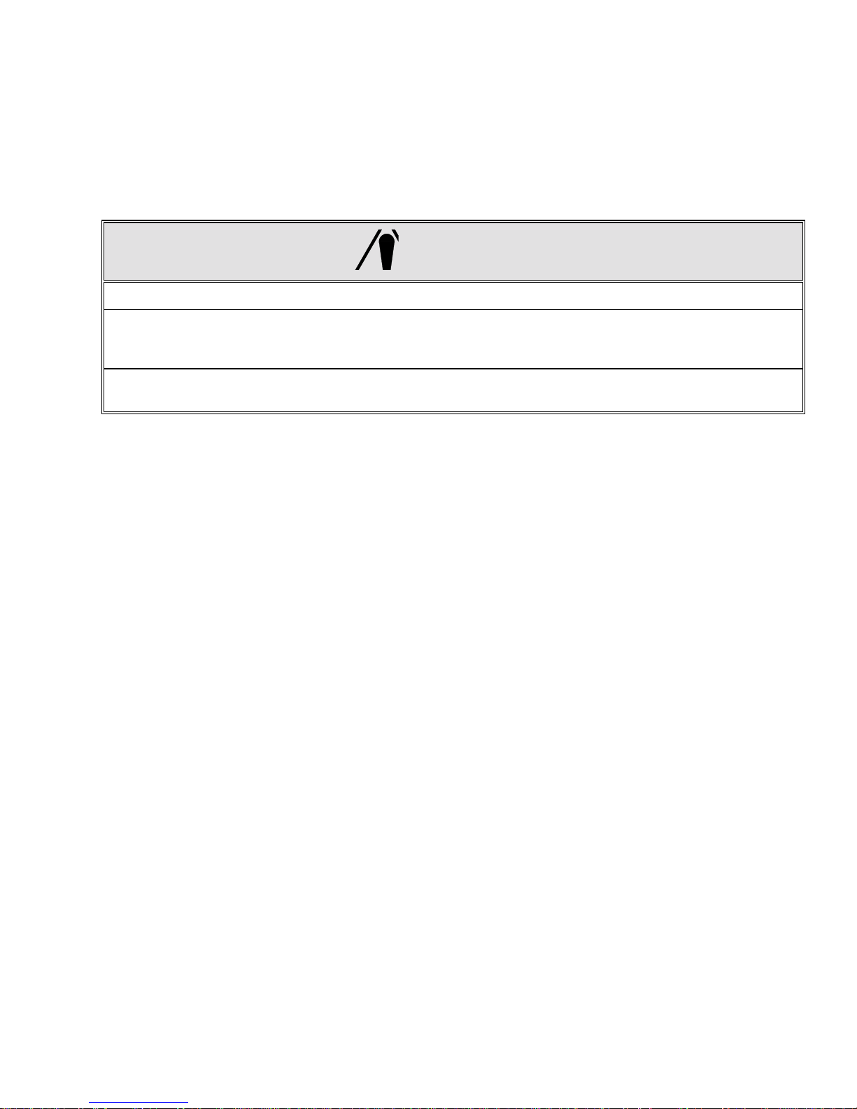
7. PREVENTIVE MAINTENANCE
This section provides instructions and procedures for maintenance of the counting scale, as well as a
troubleshooting guide to aide in problem analysis.
Clean the keyboard and covers with a soft clean cloth that has been dam pened with a m ild glass cleaner.
NOT USE ANY TYPE OF INDUSTRIAL SOLVENT. DO NOT SPRAY CLEANER DIRECTLY ONTO THE
UNIT.
5 CAUTION!
OBSERVE PRECAUTIONS FOR HANDLING ELECTROSTATIC SENSITIVE DEVICES.
DO NOT DAMAGE THE FOIL BELLOWS COVERING THE LOAD CELL OPENING OR SCALE
PERFORMANCE MAY BE EFFECTED. DO NOT TURN SCALE BASE ON ITS SIDE OR UPSIDE DOWN
WITH SUBPLATTER REMOVED.
REMOVE POWER FROM THE SCALE AND WAIT A MINIMUM OF 30 SECONDS BEFORE CONNECTING
OR DISCONNECTING ANY HARNESSES FROM PCB'S OR LOAD CELLS AS DAMAGE MAY RESULT.
7.1. TROUBLESHOOTING
If the 8572 malfunctions then perform the following troubleshooting procedures, in order, until the
malfunction is corrected.
1 - Record as much information as possible about the problem before attempting to correct the
problem. If an error code is displayed, refer to T able 7-1, in Sect ion 7.2 for s pecif ic sugges tions f or
dealing with error codes.
DO
2 - Cycle the 8572 power switch off, then back on.
3 - Verify that the scale has been properly programmed in setup.
4 - If the problem persists after verifying scale programming or if unable to enter setup mode, then
check power supply voltages listed in Section 7.3.
5 - Use s ubstitution of known good parts to correct the m alfunction. Always check DC power supply
voltages before replacing parts.
6 - If the Main PCB is replaced then ref er to Section 4 of this m anual f or proper program m ing. Do not
copy the setup of the suspected faulty PCB without verification as the problem m ay be due to a
setup error.
7 - Once the 8572 is operational, verify the problem by reinstalling the defective component and
retesting the 8572.
8 - Exchange PCBs and subassemblies are available from your authorized Toledo Scale
representative.
7.2. ERROR CODES
53
Page 61
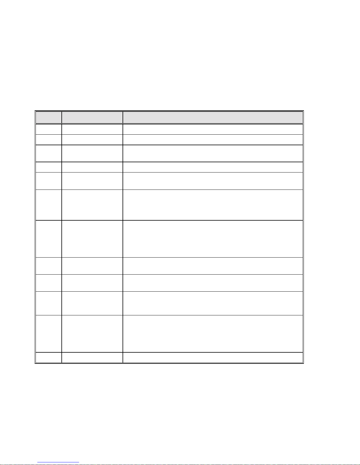
If an error code is displayed, press the
off, then back on.
If the error code recurs , refer to Tables 7-1.1 and 7-1.2 for a description of the error code and follow the
recommended corrective actions in the order listed in Table 7-1. Refer to Section 7.2 for further
troubleshooting advice if necessary.
CLEAR
key. If the error is not cleared then cycle the power switch
If an error occurs dur ing calibration then press the
and repeat the calibration procedure. If problem persists then refer to Tables 7-1.1, 7- 1.2 and follow the
recommended corrective actions in the order listed.
CLEAR
key. Verify that the correct capacity is selec ted
Error Description Recommended Corrective Action
E1 Program ROM Error Replace Eprom and Chip Carrier
E2 Internal RAM Error Replace Logic PCB
E3 Setup ROM
Memory Error
E4 External RAM Replace Logic PCB
E6 X Scale X Analog
Verify Error
Scale X
E8 X
E9 X
No Communication
With DLC Error
Scale X
Out of Range
Under Capacity
1. Access setup, reprogram, exit setup.
2. Replace Logic PCB
1. Press
2. Enter setup and recalibrate scale X.
1. Press
2. Check cables and harnesses to scale X.
3. Check Power Supply Voltages.
4. Replace Load Cell or Scale PCB.
1. Check for mechanical bind in scale X.
2. Check cables and harnesses to scale X.
3. Enter setup and recalibrate scale X.
4. Check Power Supply Voltages.
5. Replace Load Cell or Scale PCB.
CLEAR
CLEAR
key to permit operation with other scale base.
key to reset load cell.
E10 X Scale X
DLC Ram Error
E11 X Scale X
DLC ROM Error
Scale X
E13 X
E14 X Scale X
E16 X Math Overflow Error Enter setup and recalibrate scales.
DLC NOVROM Error
Out of Range
Over Capacity
1. Check Power Supply Voltages.
2. Replace Scale X Load Cell.
1. Check Power Supply Voltages.
2. Replace Scale X Load Cell.
1. Enter setup and recalibrate scale X.
2. Check Power Supply Voltages.
3. Replace Load Cell in scale X.
1. Check for mechanical bind in scale X.
2. Check cables and harnesses to scale X.
3. Enter setup and recalibrate scale X.
4. Check Power Supply Voltages.
5. Replace Load Cell or Scale PCB.
Table 7-1.1 Error Codes
54
Page 62

Error Description Recommended Corrective Action
E21 Illegal Capacity
E24 Illegal Increment Size
E32 Insufficient Weight
Test Weight too small
E34 Test Weight too Large
E35 Illegal Test Weight
E36 Invalid Build or
Insufficient Counts
E43 A Bar Code Port
I/O Error
E43 B DigiTOL® Remote
Scale PCB Port Error
CLEAR
Press
CLEAR
Press
CLEAR
Press
used in calibration MUST be at least 10% of scale capacity.
CLEAR
Press
MUST not exceed capacity.
CLEAR
Press
match scale increment size.
1. Press
greater than 35% of load cell capacity.
2. Check cables and harnesses to Scale X, verify that cables are wired
correctly.
3. Check Power Supply Voltages.
4. Replace Load Cell or Scale PCB.
1. Press
2. Check internal harnesses.
3. Check Power Supply Voltages
4. Replace Bar Code Interface PCB
1. Press
2. Check internal harnesses.
3. Check Power Supply Voltages
4. Replace Bar Code Interface PCB
key, enter proper scale capacity.
key, enter proper increment size.
key, verify scale capacity, recalibrate.
key, verify scale capacity, recalibrate.
key, verify increment size. Test weight entered must
Clear
key, verify scale capacity. Capacity selected MUST be
CLEAR
CLEAR
key, Bar Code Port will be disabled.
key, remote scale port will be disabled.
Test weights
Test weights
E E E
or
-E E E
7.3. POWER SUPPLY VOLTAGE CHECKS
7.3.1. External Power Supply
7.3.2. +12 VDC Logic Supply
Scale Out of Zero
Capture Range
Over or Under
First verify that the external 12 VDC power supply output is at least 12 VDC with les s than 300 m VAC
ripple voltage. This voltage is unregulated and is approx im ately 15 to 18 VDC when measured with the
power jack disconnected from the 8572. Measure this voltage between the inner and outer conductor
of the power jack. The inner conductor is positive and the outer conductor is ground.
This +12 VDC is used by the Logic PCB to generate all other voltages used in the 8572. This voltage
can be checked at the solder pad on the banded end of diode D8. This voltage must be between the
range of 9 to 15 VDC, maximum 300 m VAC ripple. A ground connection can be m ade at the negative
solder pad of capacitor C1. Refer to Figure 7-1 for component locations . If this voltage is missing or
out of range then check the external power supply or the charger PCB if present.
1. Press
2. Check for mechanical bind.
3. Enter setup and recalibrate scale.
Table 7-1.2 Error Codes Continued
ZERO
key to capture zero.
7.3.3. +20 VDC Supply
55
Page 63
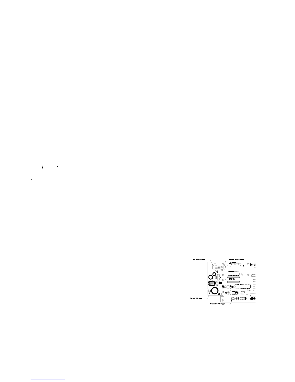
This voltage is used to power the internal DigiT OL® load cell. It is also used by the remote analog
scale option, the remote DigiTOL® scale option, and the bar code option. Ther e is an unregulated +22
VDC that is the raw supply to the +20 VDC regulator. The unregulated +22 VDC can be checked
across the solder pads of capacitor C1 on the logic PCB. This voltage m ust be within the range of 20
VDC to 30 VDC. The regulated +20 VDC can be checked ac ross the solder pads of capacitor C2.
Refer to Figure 11 for component location. The regulated +20 VDC must be within the range of 19 VDC
to 21 VDC. If the +12 VDC logic supply is ok and either of these voltages ar e missing or out of range
the logic PCB must be replaced.
7.3.4. +5 VDC Logic Supply
This voltage is used to power all the logic circ uitry on the Logic PCB. This voltage can be c hecked on
pin 1 of integrated circuit U14. Refer to Figure 7-1 for com ponent location. T his voltage m ust be within
the range of +4.85 VDC to +5.2 VDC, maximum ripple voltage of 0.05 VAC. If the +12 VDC logic
supply checks ok and this voltage is missing or out of range the logic PCB must be replaced.
7.3.5. +12.5 VDC Analog Load Cell Excitation
The remote analog scale option has a regulated +12.5 VDC output to proved ex citation voltage to the
analog load cells. This excitation voltage can be c hecked across pins 3 and 6 of connector J2 of the
Analog PCB. The excitation voltage must be within the r ange of +12.4 to +12.6 VDC, m axim um ripple
voltage of 0.01 VAC. The analog excitation voltage is derived from the +20 VDC supply.
Figure 7-1 Logic PCB Power Supply Checks
7.4. LOAD CELL REPLACEMENT
Remove power from the scale by turning off the power switch located on the right side of the base near the
front. Unplug the external power supply and external battery or internal battery if present.
Remove the platter, sub-platter, dead deck (lower capacity scales), and cover assemblies.
56
Page 64

6
CAUTION!
On 8572-0002, 1002 versions that use the 3.75 kg load cell, reinstall the two #8-32 shipping
screws through the sub-platter into the two hex standoffs. Refer to Figure 7-2. Do not tighten
these screws down. They are used to keep the sub-platter from twisting when the sub-platter
mounting screws are tightened or loosened. DAMAGE TO THE LOAD CELL MAY RESULT IF
THIS PROCEDURE IS NOT FOLLOWED. Remove the two #8-32 screws, after the sub-platter
mounting screws are tightened or loosened.
Figure 7-2 Low Capacity Shipping Hardware
Loosen the metal cover with the foil bellows that cover s the load cell. Do this by removing the four s crews
that secure it to the base.
Disconnect the load cell harness from the load cell and set the cover assembly with the foil bellows aside.
Remove the space block on top of the load cell and turn the scale on its side.
Remove the two hex head screws from the bottom of the sc ale that secure the load c ell. The load c ell can
now be removed. Be sure to retrieve the spacer under the load cell.
With the scale still on its side, reinsert the two hex head screws through the base and slide the bottom
spacer over the screws.
Carefully install the new load cell by threading the screws into the bottom of the load cell. Tighten the
mounting screws to finger tightness.
Stand the scale base upright and reinstall the top load cell spacer.
Reattach the load cell harness (that is attached to the metal cover with the foil bellows) to the load cell.
Secure the metal cover to its original position above the load cell. T ighten the four screws that hold the
cover in place.
Reinstall the cover and dead deck (on low capacity units).
57
Page 65

Reattach the sub-platter. Refer to the caution at beginning of load cell replacem ent procedure for 85720002, 1002 units.
Check that the corner and center overload stops are aligned with the overload stop screws.
Tighten all (4) load cell and sub-platter m ounting screws to 75 - 85 inch/pounds. Use a torque wrench to
ensure proper screw tension without over tightening.
Place the platter on the sub-platter.
Reconnect the internal battery or external battery if present and reconnect the external power supply.
Reapply power to the 8572 by means of the power switch located on the right side of the base near the
front.
Verify operation and calibration of the new load cell as described in the calibration and operation section of
the technical manual.
Note
: Overload stop clearance gaps must be checked after replacement of the load cell to provide proper
protection to the new load cell.
7.5. OVERLOAD STOP ADJUSTMENT
The overload stops mu st be adjusted when the load cell and/or sub-platter has been replaced. There c an
be up to six overload stop positions, identified as X1 through X7. Factory numbers 8572-0002, and 1002, (5
lb capacity) versions use stops X1, X2, and X3. Overload s top X1 is located under the load cell. Refer to
Figure 7-3 for overload stop locations. F actory numbers 8572-0003, - 0004, 0005, 0006, 1003, 1004, 1005,
and 1006 (25 lb capacity and greater) scales use stops X2 through X7, refer to Figure 7-4.
Assemble the base, load cell, and sub-platter as described in the load cell replacement procedure in section
7.3. Mounting screws should be snug but not tight.
Check that the corner and center over load stops are aligned with the overload adjus tment sc rews. Tighten
all (4) load cell and sub-platter mounting s crews to 75 - 85 inch/pounds. Use a torque wrench to ensure
proper screw tension without over tightening.
Note
: All sub-platter and load cell mounting screws must be tightened to the proper specification before
adjusting overload stops. Failure to do so m ay result in the overload stops being set incorre ctly and failure of
the load cell.
7 CAUTION!
Never apply weight exceeding the capacity of the scale or shock load
the scale if the overload stops have not been set.
7.5.1. Low Capacity Overload Adjustment (8572-0002, and 1002)
5 lb capacity overload stops are set by observing the expanded weight display as test weights are
placed in specific locations on the scale platter.
With power applied, place the scale into the test m ode (setup step
X1, X2, and X3.
[69 1]
) and loosen overload stops
The various test weights specified in T able 7-1 are placed in turn on the center of the platter to adj ust
X1, the right rear corner to adjust X 2, and the right front corner to adjust X3. Ref er to Figure 7-3 and
Table 7-1.
58
Page 66
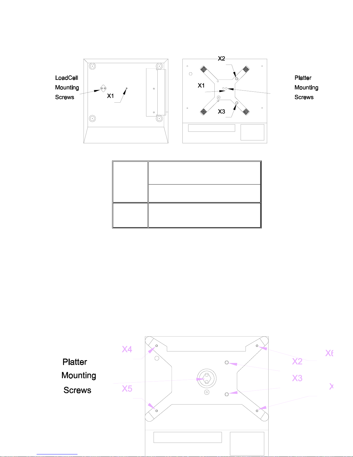
Tighten the overload screw for a given overload s top until the display weight just starts to change. T his
indicates the overload screw is just touching the stop. Repeat this procedure for each of the three
overload stops X1, X2, and X3.
Figure 7-3 Low Capacity Overload Stops
Overload
Factory Number (Load Cell Capacity)
Stop
Position
8572-0002, 1002
3.75 kg Load Cell
X1
X2
X3
6.5 lb
6 lb
6 lb
Table 7-1 Lower Capacity Overload Stop Adjustment
7.5.2. Higher Capacity Overload Adjustment
(8572-0003, 0004, 0005, 0006, 1003, 1004, 1005, and 1006)
10 lb and greater capacity scales overload stops are set by meas uring the gap between the overload
stop and the overload screw. The gap is adjusted until it meets the s pecif ication listed in T able 7-2. All
dimensions are listed in inches . Use round wire gauges, or the wire size equivalent drill bit to m easur e
the overload stop gap.
DO NOT use flat feeler gauges to measure overload stop gap
.
- Tighten the overload screw until the gap is smaller than the wire gauge.
- Hold the wire gauge against the gap with a slight pressure.
- Slowly loosen the overload screw until the wire gauge snaps through the gap.
- Repeat this procedure for each of the six overloads X2, X3, X3, X4, X5, X6, and X7. Refer to
Figure 7-4 for overload stop location.
59
Page 67

Figure 7-4 Higher Capacity Overload Stops
Over
Load
Stop
8572-0003, 1003
7.5 kg Load Cell
X2 0.014"/#79 0.015"/#79 0.016"/#78 0.024"/#73
X3 0.016"/#78 0.017"/#77 0.020"/#76 0.026"/#71
X4 0.047"/#56 0.064"/#52 0.084"/#45 0.153"/#24
X5 0.047"/#56 0.059"/#53 0.057"/#54 0.094"/#42
X6 0.047"/#56 0.064"/#52 0.084"/#45 0.153"/#24
X7 0.047"/#56 0.059"/#53 0.057"/#54 0.094"/#42
Factory Number and Load Cell Capacity
8572-0004, 1004
15 kg Load Cell
8572-0005, 1005
30 kg Load Cell
TOL.
8572-0006, 1006
60 kg Load Cell
±.001"
±.005"
Table 7-2 Higher Capacity, Overload Stop Gap Specification
7.6. KEYBOARD REPLACEMENT
Remove power from the scale by turning off the power switch located on the right side of the base near the
front. Unplug the external power supply and battery if present.
"
8 CAUTION!
Remove power from the scale and wait a minimum of 30 seconds before connecting or disconnecting any
harnesses from PCB's or load cells as damage may result.
On 8572-0002, 1002 versions that use the 3.75 kg load cell, reinstall the two #8-32 shipping screws
through the sub-platter into the two hex standoffs. Refer to Figure 7-2. Do not tighten these screws
down. They are used to keep the sub-platter from twisting when the sub-platter mounting screws are
tightened or loosened. DAMAGE TO THE LOAD CELL MAY RESULT IF THIS PROCEDURE IS NOT
FOLLOWED. After the sub-platter mounting screws are tightened or loosened, the two #8-32 screws are
removed.
Remove the platter, sub-platter, dead deck (lower capacity scales), and cover assemblies.
Unplug the keyboard ribbon connector from the Logic PCB and gently slide the ribbon harness through the
flat cable clamp, refer to Figure 7-5. Do not remove the flat cable clamp from the cover assembly.
60
Page 68

Figure 7-5 Keyboard Mounting
Remove the four retaining screws that hold the keyboard backing plate. Remove the backing plate and
keyboard assembly. Refer Figure 15.
Install the new keyboard assembly, backing plate and four retaining screws.
Verify the revision level of the Logic PCB. The revision level is the leading prefix of the PCB part num ber, (for
example: "B134771 00A" is a "B" revision part num ber). "A" and lower revision Logic PCBs require a double
twist in the keyboard ribbon harness to permit pin 1 of the keyboard ribbon harnes s to plug into pin 1 of the J7
connector on the Logic PCB. "B" and higher revision Logic PCBs reverse the location of pin 1 of the J7
connector and no longer require the double twist of the keyboard harness.
After folding the keyboard ribbon harness correctly, slide the ribbon harness back through the clamp.
Insert the keyboard ribbon harness plug P7 into the Logic PCB connector J7. Verify that pin 1 of the keyboard
harness is inserted into pin 1 of c onnector J7 on the logic PCB. "A" and lower re vision Logic PCBs have pin 1
located towards the rear of the enclosure. "B" and higher revision Logic PCBs have pin 1 of connector J7
located towards the front of the enclosure. The keyboard ribbon harness pin 1 is marked by means of a
diamond on the side of the ribbon harness plug. Refer to Figure 7-6.
7.7. LOGIC PCB REPLACEMENT
Remove power from the scale and wait a minimum of 30 seconds before connecting or disconnecting any
harnesses from PCBs or load cells as damage may result.
On 8572-0002, 1002 that use the 3.75 kg load cell, reinstall the two #8-32 shipping screws through the subplatter into the two hex standoffs. Refer to Figure 7-2. Do not tighten these screws down. They are used to
Figure 7-6 Keyboard Connector Pin 1
9CAUTION!
61
Page 69

keep the sub-platter from twisting when the sub-platter mounting screws are tightened or loosened. DAMAGE
TO THE LOAD CELL MAY RESULT IF THIS PROCEDURE IS NOT FOLLOWED. After the sub-platter
mounting screws are tightened or loosened, the two #8-32 screws are removed.
!
Remove power from the scale by turning off the power switch located on the right side of the base near the
front. Unplug the external power supply and external battery or internal battery if present.
!
Remove the platter, sub-platter, dead deck ( lower capacity scales), and cover assemblies.
Remove all optional PCBs, harnesses and r etaining screws, then remove the Logic PCB from the cover
assembly.
!
Remove the Eprom and Chip Carrier (*135629 00A) from its socket on the logic PCB.
!
Insert the logic PCB into an antistatic bag (112736 00B) immediately.
!
Insert the Eprom/Chip Carrier (*135629 00A) into the empty socket on the replacement Logic PCB.
Replacement Logic PCBs are not shipped with the Eprom/Chip Carrier.
!
Install the new Logic PCB, reinstall all retaining screws, harnesses and optional PCBs . Verify that pin 1 of
the keyboard harness is inserted into pin 1 of c onnector J7 on the logic PCB. "A" and lower revis ion Logic
PCBs have pin 1 located towards the rear of the enclosure. "B" and higher revision Logic PCBs have pin 1
of connector J7 located towards the front of the enclos ure. Refer to Keyboard replacement procedure in
Section 7.5.
7.8. RECOMMENDED SPARE PARTS
*136139 00A Logic PCB
*135629 00A Eprom/Chip Carrier
*134773 00A Display PCB
*136149 00A Keyboard Assembly
*135156 00A 0.6 A, 12 VDC External Power Supply
*(Refer to Table 7-3) DigiTOL® Load Cell
Factory Number Load Cell Capacity Part Number
8572-0002, 1002 3.75 kg *134789 00A
8572-0003, 1003 7.5 kg *134790 00A
8572-0004, 1004 15 kg *134791 00A
8572-0005, 1005 30 kg *134792 00A
8572-0006, 1006 60 kg *134793 00A
Table 7-3 Load Cell Part Numbers
(*) Part numbers listed may have letter prefix.
7.9. OPTIONAL KITS
7.9.1. External 120 VAC/1.5A Power Supply
(Required if any other KOPs are installed)
0919-0028Sales Part Number
*135693 00A Service Part Number
7.9.2. Internal Battery KOP
0919-0031Sales Part Number
62
Page 70

*135696 00A Service Part Number
7.9.3. External Battery KOP
0919-0032Sales Part Number
*135698 00A Service Part Number
7.9.4. Remote Analog Scale KOP
0901-0283Sale Part Number
*135690 00A Service Part Number
7.9.5. Remote DigiTOL® Scale KOP
0901-0281Sales Part Number
*135686 00A Service Part Number
7.9.6. Bar Code Wand KOP
0901-0279Sales Part Number
*135522 00A Service Part Number
7.9.7. Bar Code Scanner Gun KOP
0901-0280Sales part Number
*135492 00A Service Part Number
(*) Part numbers listed may have letter prefix.
Note: Bar Code KOPs 0901-0279 and 0901-0280 require the 0901-0281 Remote DigiT OL® Scale KOP to
operate. Analog scale bases can be used with the 0901-0283 Remote Analog Scale KOP even though
the remote DigiTOL® Scale KOP is installed to support bar code operation.
63
Page 71

- For Your Notes -
64
Page 72

8. PARTS CATALOG
8.1. EXTERIOR VIEW LOW CAPACITY VERSIONS (Factory Numbers 8572-0002, 1002)
REF PART
N.S.
N.S.
N.S.
10
11
1
2
3
4
5
6
7
8
9
NUMBER
115193 00A
126983 00A
R03575 00A
126984 00A
126987 00B
R03719 00A
R03708 00A
119133 00A
136149 00A
122312 00B
136138 00A
125662 00A
116033 00A
125134 00B
DESCRIPTION QTY REF PART
Plastic Platter Assembly
Hook Fastener
Set Screw, 3/8-24 X 1/2"
Sub-Platter Assembly
Dead Deck
Nylon Screw, #8-32 X 3/4"
Nylon Washer, #8
Rocker Switch
Keyboard Assembly (U.S.A.)
Switch Membrane (Export)
Keyboard Overlay (Export)
Keyboard Gasket (Export)
Static Caution
Decorative Whi te Bezel
Part number listed may have a letter prefix. (NS) Not shown.
8.2. EXTERIOR VIEW HIGHER CAPACITY VERSIONS
(Factory Numbers 8572-0003, 0004, 0005, 0006, 1003, 1004, 1005, and 1006)
NUMBER
1
12
14
15
16
17
18
19
21
22
23
24
134788 00A
138911 00A
R03816 00A
102689 00A
135156 00A
135693 00A
137962 00A
122692 00A
R03508 00A
115190 00A
131919 00A
129350 00B
R03831 00A
R01145 130
4
2
1
1
5
N.S.
5
N.S.
1
1
1
1
1
1
1
Display Lens (U.S.A .)
Display Lens (Export)
Setup Hole Plug
Level Bubble
120 VAC/0.6 mA Transf ormer (U.S.A.)
120 VAC/1.5 A, Transformer (U.S.A.)
220 VAC/0.6 mA Transf ormer (Export)
Set Screw Caution Label
Screw, 1/4-28 X 1-1/2"
Hook & Loop Fasteners (NS)
Load Cell Caution Label
White Plastic Cover
Shipping O-Ring (NS)
Shipping Screw, #8-32 X 3/4" (NS)
DESCRIPTION QTY
1
1
1
1
1
1
1
1
2
4
1
1
2
2
65
Page 73

REF PART
N.S.
N.S.
N.S.
1
2
3
4
5
6
7
8
9
NUMBER
126986 00A
122347 00A
R03508 00A
R03575 00A
126972 00A
126972 00B
R03646 00A
120509 00A
135156 00A
135693 00A
137962 00A
136149 00A
122312 00B
8.3. BOTTOM VIEW
DESCRIPTION QTY REF PART
Black Steel Platter
Platter Pad
Cap Screw, 1/4-28 X 1-1/2"
Set Screw, 3/8-24 X 1/2"
Sub-Platter Assembly (X003, X004)
Sub-Platter Assembly (X005, X006)
Set Screw, 1/4-28 X 1/2"
Conductive Pad
120 VAC/0.6 mA Transf ormer (U.S.A.)
120 VAC/1.5 A, Transformer (U.S.A.)
220 VAC/0.6 mA Transf ormer (Export)
Keyboard Assembly (U.S.A.)
Switch Membrane (Export)
1
N.S.
1
N.S.1
2
2
11
1
N.S.
1
12
2
13
4
14
1
15
1
16
1
18
1
19
1
0
NUMBER
136138 00A
125662 00A
119133 00A
134788 00A
138911 00A
125134 00A
129350 00A
116033 00A
R03030 00A
R03573 00A
102689 00A
122692 00A
(X00X) Factory Number 8572-X00X
Part numbers listed may have a letter prefix. (N.S.) = not shown.
66
DESCRIPTION QTY
Keyboard Overlay (Export)
Keyboard Gasket
(Export)Power Switch
Display Lens (U.S.A .)
Display Lens (Export)
Decorative Whi te Bezel
White Plastic Cover
Static Caution Label
Screw, 8-32 X 3/8"
Black Sealing Screw
Level Bubble
SetScrew Caution Label
1
1
1
1
1
1
1
1
4
1
1
1
Page 74

REF PART NUMBER DESCRIPTION QTY
1
2
3
4
5
122410 00A
001874 00B
R03020 00A
R03046 00A
126985 00A
124224 00A
6
7
8
9
10
11
12
135705 00A
135706 00A
R03090 00A
126334 00A
134784 00A
130850 00A
R03507 00A
R02401 00A
13
122339 00A
(*) Part number listed may have a letter prefix. (NS) Not shown.
8.4. PCBs AND TOP COVER
Leveling Leg
Nut, 5/16-18
Black Plastic Hole Plug, 7/8"
Overload Screw, 1/4-28 X 1" (X002)
Base Assembly (X002, X003)
Base Assembly (X004, X005, X006)
Printer Harness
Power Harness
Screw, #6-32 X 3/8"
Standoff, #6-32 X 3/4"
Power/Printer Mounting Bracket
Cover Plate
Cap Screw 1/4-28 X 1" (0002 thru 0005)
Cap Screw 1/4-28 X 3/4" (0006) only
Bottom Load Cell Spacer (0002 thru 0005)
(X00X) Factory Number 8572-X00X.
4
4
2
1
1
1
1
1
4
2
1
1
2
2
1
67
Page 75

REF PART
NUMBER
DESCRIPTION QTY
1
2
3
N.S.
N.S.N
.S.
4
5
6
7
8
9
10
11
12
13
R03997 00A
123134 00A
136149 00A
122312 00B
136138 00A
125662 00A
129350 00B
129350 00A
R02459 00A
129340 00A
R03225 00A
135629 00A
136139 00A
135783 00A
R03495 00A
135704 00A
134773 00A
SEMS Screw, #6-32 X 3/8"
Keyboard Bracket
Keyboard Assemble
Switch Membrane (Export)
Keyboard Overlay (Export)
Keyboard Gasket (Export)
White Cover (X002, X003)
White Cover (X004, X005, X006)
Blind Plastic Rivet
Battery Access Cover Plate
Plastite Screw, #6-32 X 1/4"
Eprom and Chip Carrier
Logic PCB
Back Plane Shield (N.S.)
Plastite Screw, #6-32 X 5/8"
Display Harness
Display PCB
(*) Part number listed may have a letter prefix.
(N.S.) Not shown.
8.5. INTERIOR OF BASE
4
1
1
1
1
1
1
1
4
1
4
1
1
1
2
1
1
68
Page 76
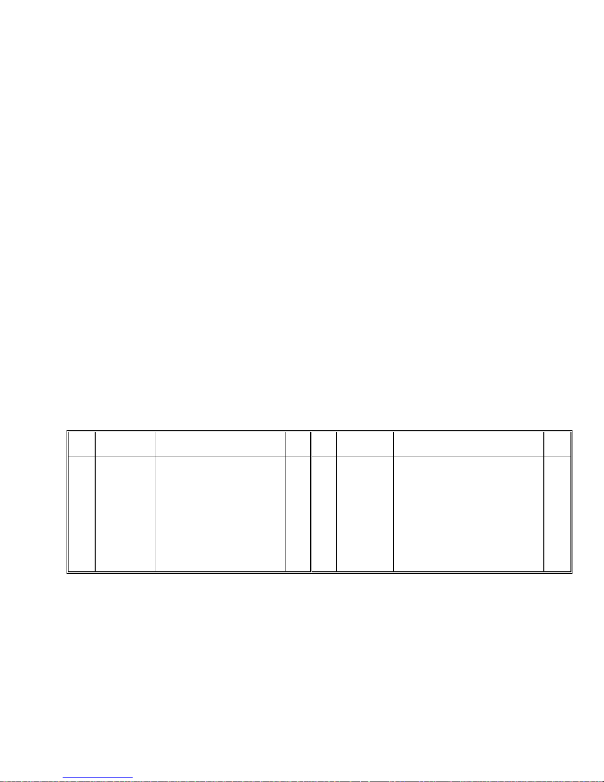
REF PART
N.S.
1
1
2
3
4
5
6
NUMBER
123132 00A
122324 00A
123626 00A
154360001
125789 00A
122718 00A
R01862 050
134789 00A
134790 00A
134791 00A
132792 00A
134793 00A
L/C Cover Assem. Cons i sts Of:
4-40 X 3/16" Screw
3.75 kg, digital load cell (X002)
7 kg, digital load cell (X003)
15 kg, digital load cell (X004)
30 kg, digital load cell (X005)
60 kg, digital load cell (X006)
DESCRIPTION QTY REF PART
Cavity Cover
Bellows, RFI Shield
Copper Tape
4-40 Standoff
Internal Load Cell Harness
Part numbers listed may have a letter prefix. (N.S.) = not shown.
9. INTERCONNECT DRAWING
NUMBER
1
7
8
9
10
11
12
13
14
15
R02180 050
119133 00A
126985 00A
124244 00A
124718 00A
135706 00A
135705 00A
127395 00A
125657 00A
122693 00A
130093 00A
R02180 050
1
1
10"
2
1
2
1
1
1
1
1
(X00X) Factory Number 8572-X00X
DESCRIPTION QTY
#8-32 X 3/8" Screw
Power Switch
Scale Base (X002, X003)
Scale Base (X004, X005, X006)
1/2" Cable Clamp
Power Harness
Printer Harness
Spacer Block (X002 - X005)
Space Block (X006)
Load Cell Harness
#8-32 X .56" Standoff (X002, X003)
#8-32 X 3/8" Screw (X0004 - X006)
4
1
1
1
1
1
1
1
1
1
2
2
69
Page 77

70
Page 78

Page 79

Toledo Scale
Industrial Products
350 W. Wilson Bridge Road
Worthington, Ohio 43085
Phone (614) 438-4511
FAX (614) 438-4770
P/N A136147 00A
Printed in U.S.A.
Revised 1/92
© Mettler-Toledo Inc.
 Loading...