

Page 1

TOHO ELECTRONICS INC.
Operation Manual, Communications
(TOHO protocol and MODBUS)
Model: TTX-700
Designation: Module Controller
Page 2

Contents
1. Before using the product......................................................................................................................... 4
1.1 On this operation manual .............................................................................................................4
1.2 What can be done with communications......................................................................................4
1.3 Positioning communications (priority ranking)............................................................................ 4
1.4 Setting before communications.................................................................................................... 4
2. Settings regarding TOHO communications ............................................................................................5
2.1 Overview...................................................................................................................................... 5
2.2 Setting a data length..................................................................................................................... 6
2.3 Setting a stop bit length................................................................................................................ 6
2.4 Setting a parity .............................................................................................................................6
2.5 Setting whether to conduct a BCC check..................................................................................... 6
2.6 Setting a communications speed ..................................................................................................6
2.7 Setting an address......................................................................................................................... 7
2.8 Setting a response delay............................................................................................................... 7
2.9 Switching communications mode ................................................................................................ 7
3. TOHO communications control.............................................................................................................. 8
3.1 Communications procedure.......................................................................................................... 8
3.2 Message types .............................................................................................................................. 8
3.3 Composition of a request message
(transmitted from a high-level computer to this product)............................................................. 9
3.4 Composition of a response message
(transmitted from this product to a high-level computer)........................................................... 10
3.5 Description of codes....................................................................................................................11
3.6 Communications precautions .....................................................................................................13
4. Examples of TOHO communications ...................................................................................................15
4.1 Examples of communications to be read.................................................................................... 15
4.2 Examples of communications to be written............................................................................... 15
5. Settings regarding MODBUS communications.................................................................................... 17
5.1 Overview.................................................................................................................................... 17
5.2 Setting a data length................................................................................................................... 18
5.3 Setting a stop bit length.............................................................................................................. 18
5.4 Setting a parity ........................................................................................................................... 18
5.5 Setting a communications speed ................................................................................................18
5.6 Setting an address....................................................................................................................... 19
5.7 Setting a response delay............................................................................................................. 19
5.8 Switching communications mode .............................................................................................. 19
2
Page 3

6 MODBUS communications control...................................................................................................... 20
6.1 Communications procedure........................................................................................................ 20
6.2 Message types ............................................................................................................................ 20
6.3 Composition of an RTU request message
(transmitted from a high-level computer to this product)........................................................... 21
6.4 Composition of an RTU response message
(transmitted from this product to a high-level computer)........................................................... 22
6.5 Description of RTU codes.......................................................................................................... 23
6.6 Precautions on RTU communications ........................................................................................25
6.7 Example of CRC-16 calculations ...............................................................................................26
6.8 Composition of an ASCII request message
(transmitted from a high-level computer to this product)........................................................... 27
6.9 Composition of ASCII response messages
(transmitted from this product to a high-level computer)...........................................................28
6.10 Description of ASCII codes........................................................................................................ 30
6.11 Precautions on ASCII communications...................................................................................... 32
6.12 Example of LRC calculations..................................................................................................... 33
7. Specifications........................................................................................................................................ 34
7.1 Communications standard category: Compliant with EIA standard RS-485 .............................34
7.2 Communications specifications.................................................................................................. 34
8. Connections........................................................................................................................................... 35
8.1 Connections for the RS-485....................................................................................................... 35
9. Table of ASCII codes............................................................................................................................ 36
10. Table of identifiers (codes).................................................................................................................... 37
3
Page 4

1. Before using the product
1.1 On this operation manual
This is an operation manual regarding communications with a TTX-700 (hereinafter referred to as
"this product").
1.2 What can be done with communications
With this product, users can write and read items specified in "10. Table of identifiers," such as
"reconfiguring, starting, or stopping items that are operable with the front keys" and "reading
information displayable on the display."
However, reading and writing with ordinary commands are performed with regarding to the RAM in
this product. Written data can be turned back into the values before the writing (the values stored on
the EEPROM) by turning power off and on again. To store the written data on the EEPROM of this
product, execute a store request message. (See "3.6. Communications precautions.")
Settings regarding options not added and other unnecessary settings cannot be read or written.
1.3 Positioning communications (priority ranking)
Data and parameters in this product can be changed with keys while in operation in the
communications mode.
While this product is in operation in the RO (read-only) mode, no data or parameter setting can be
changed by communications. (Provided that communications modes can be changed.)
1.4 Setting before communications
Before performing communications, this product must be set.
This product is compatible with the TOHO communications protocol and the MODBUS
communications (RTU, ASCII).
Select a protocol with the protocol setting ( ) on communications 1/2 setting ( ). For the
TOHO communications protocol, see "2. Settings regarding TOHO communications." For the
MODBUS communications protocol, see "5. Settings regarding MODBUS communications."
4
Page 5
2. Settings regarding TOHO communications
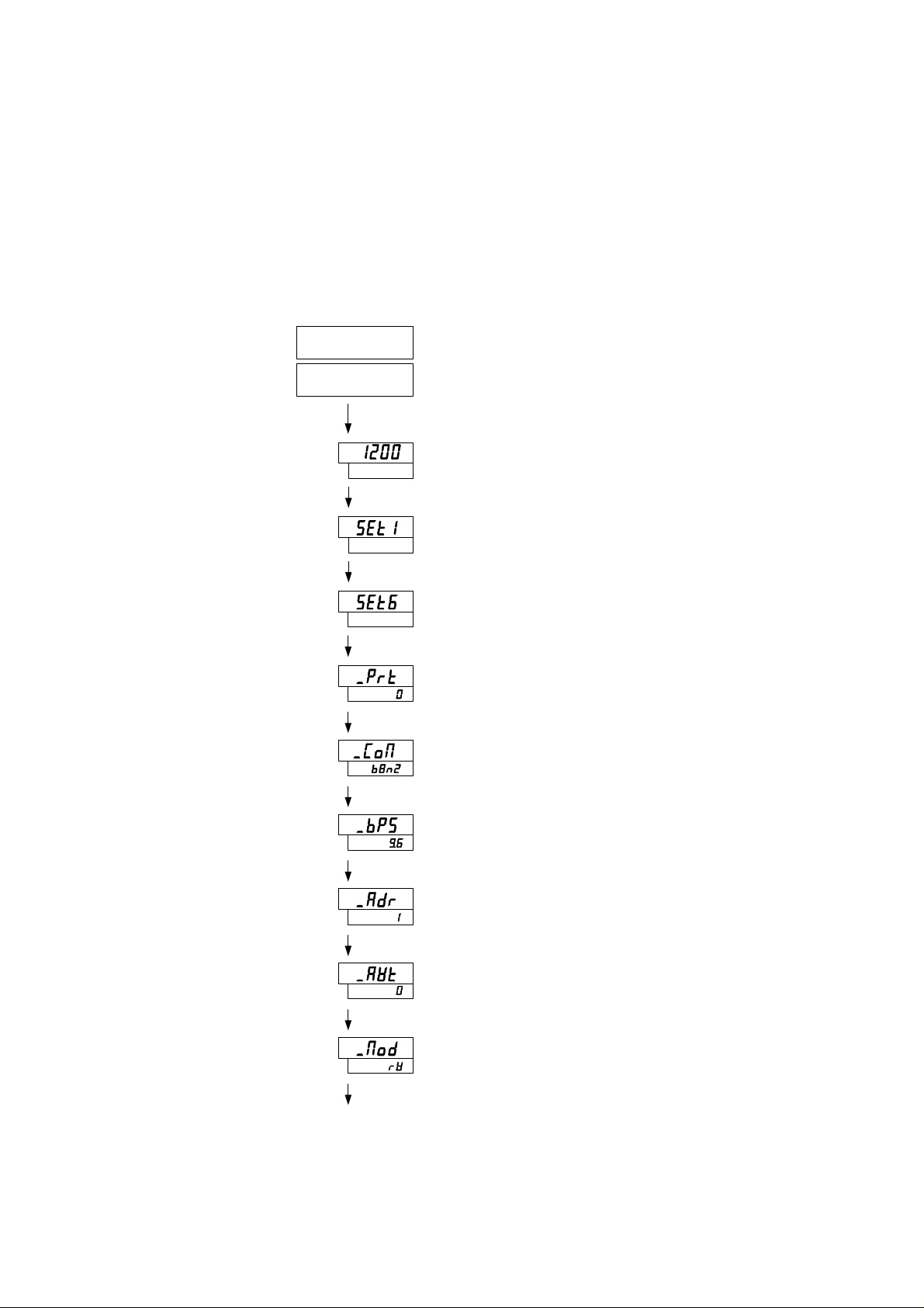
2.1 Overview
Before communications is performed, initial settings must be made on this product. Enter such
settings with the keys on the front panel. To switch to a series of setting screens, take the steps
described below. For details, see the operation manual furnished with this product.
Power ON
Initial setting
Operation mode screen
MODE key at least 2 seconds
(Setting mode selection screen)
▲ ▼key
MODE key
MODE key
MODE key
MODE key
MODE key
MODE key
Select a communications setting mode
Set a communications protocol
Set a communications parameter
Set a communications speed
Set a communications address
Set a communications response delay
Set communications mode switchover
MODE key
When the settings are over, press the MODE key at least 2 seconds to go back to the operation mode.
The parameters indicated above are initial values.
5
Page 6
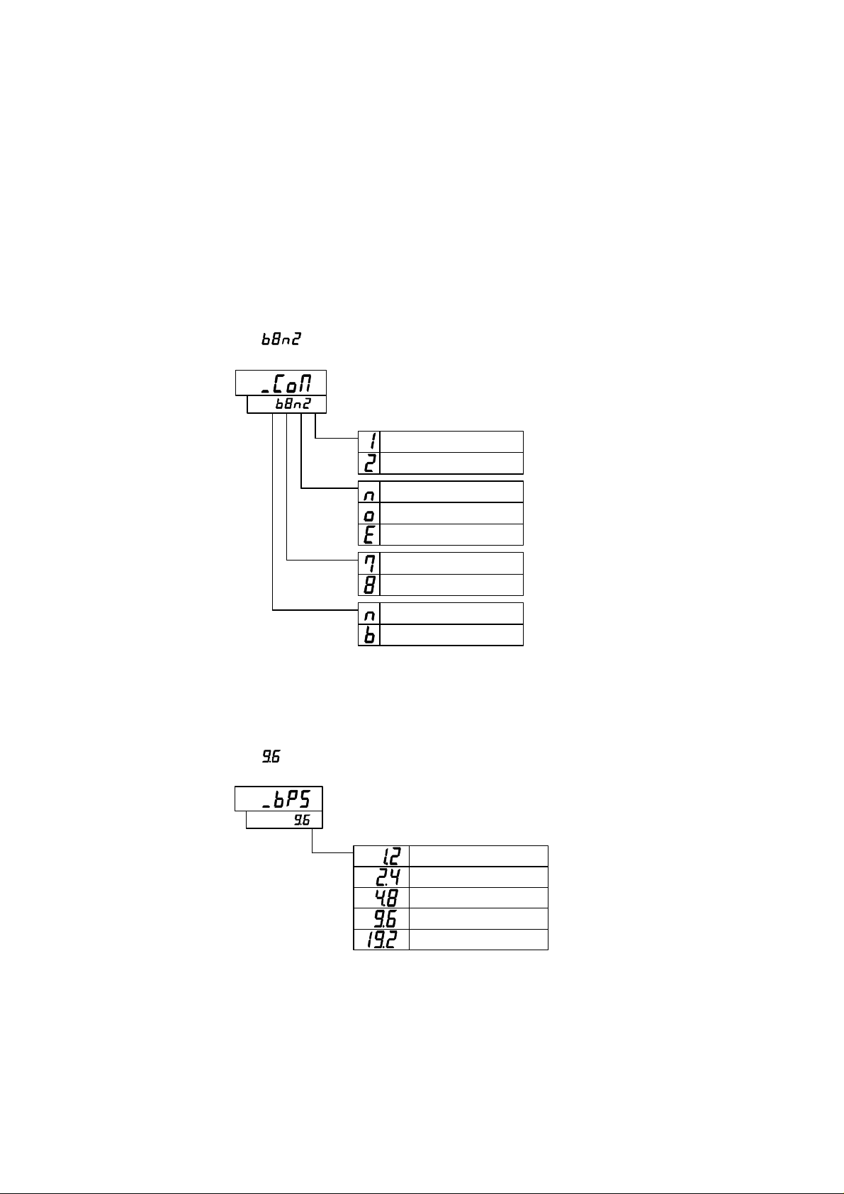
2.2 Setting a data length
2.3 Setting a stop bit length
2.4 Setting a parity
2.5 Setting whether to conduct a BCC check
While in the "Set a communications parameter" screen on the preceding page, operate the ▲ and
▼ keys to make the settings.
The initial value is [ ].
Stop bit 1
Stop bit 2
No parity
Odd parity
Even parity
Data length, 7 bits
Data length, 8 bits
BCC check disabled
BCC check enabled
2.6 Setting a communications speed
While in the "Set a communications speed" screen on the preceding page, operate the ▲ and ▼
keys to make the settings.
The initial value is [ ].
1200bps
2400bps
4800bps
9600bps
19200bps
6
Page 7
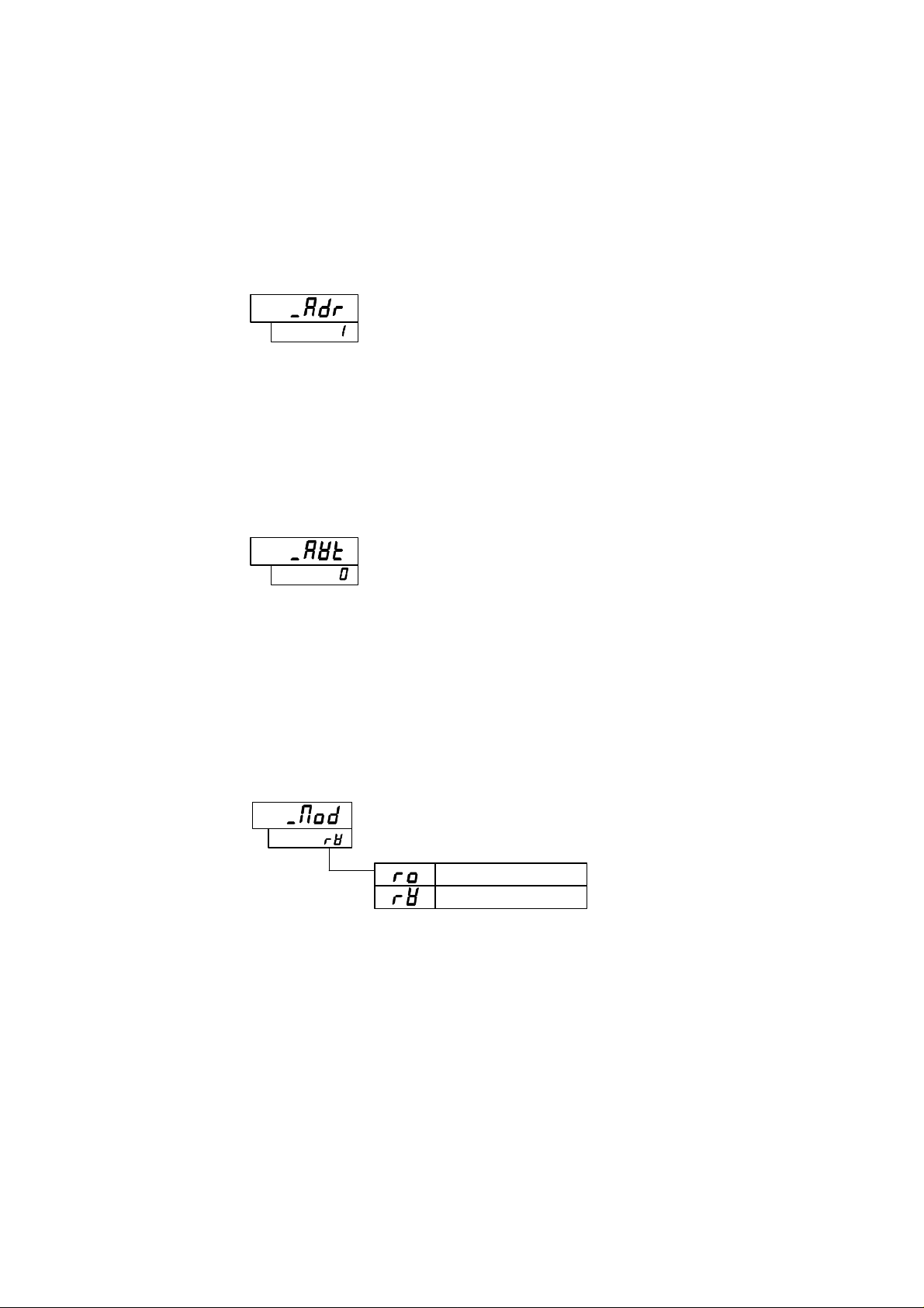
2.7 Setting an address
While in the "Set a communications address" screen on the preceding page, operate the ▲ and ▼
keys to make the settings.
The initial value is •.
Setting range: 1 to 99 stations (It cannot be set to a 0.)
2.8 Setting a response delay
Set a time from the time when the high-level computer finished sending a "request message" until
the time when it delivers the line and enters an input state.
While in the "Set a response delay" on the preceding page, operate the ▲ and ▼ keys to make the
settings.
The initial value is 0.
Setting range: 0 to 250ms
* If the response delay is set to a short setting, the communications may not be conducted normally.
* In a real operation, the processing time for this product will be added, in addition to the response
delay.
2.9 Switching communications mode
While in the "Set communications mode switchover" screen on the preceding page, operate the ▲
and ▼ keys to make the settings.
Read only
Read and write
7
Page 8
3. TOHO communications control
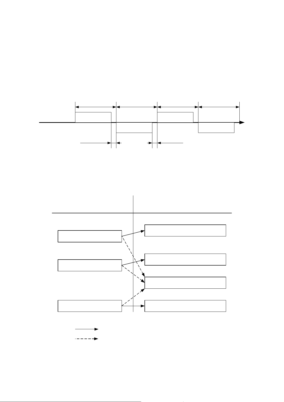
3.1 Communications procedure
This product returns a "response message" in response to a "request message" from a high-level
computer. It therefore does not initiate a transmission.
Transmitted by a high-
level computer
High-level computer
This product
See "2.8. Set a response delay."
See "3.6.1. Communications timing."
Request message
Response delay:
0-250ms
Transmitted by this
product
Request message
3.2 Message types
n Messages are roughly divided into the following types:
Request message (transmitted
from a high-level computer)
Read request message
Transmitted by a high-
level computer
Request message
1ms or more
See 3.6.2. "Interval between requests."
Response message (transmitted
from this product)
Receipt acknowledgement and data
response
Transmitted by this
product
Request message
Write complete response
Write request message
Reception error and error description
response
Store request message
: Response when a normal "request message" is received
: When a received "request message" contains an error
Store complete response
n All codes (except for BCC) from STX data to ETX are expressed in ASCII codes.
n In assembling a program for a high-level computer, see "10. Table of identifiers (codes)" and "9.
Table of ASCII codes" at the end of the book.
8
Page 9
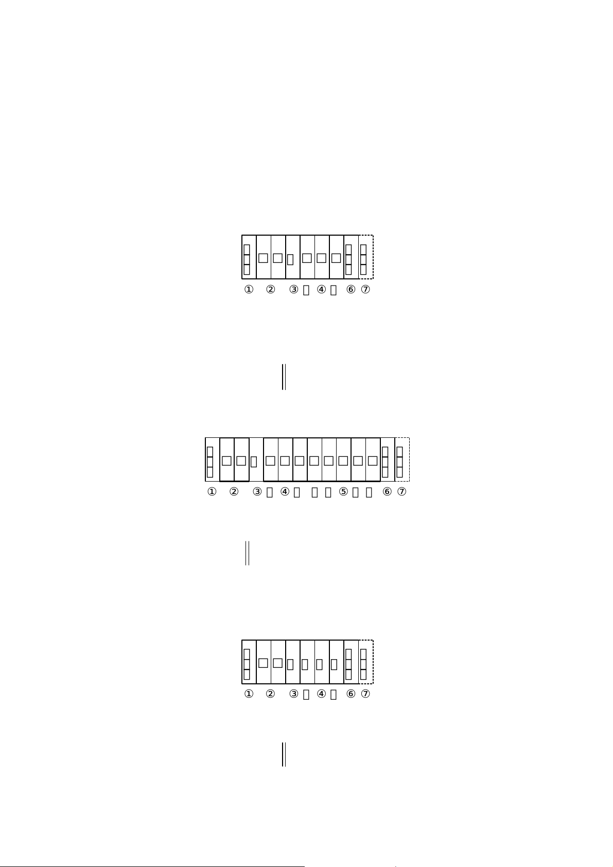
3.3 Composition of a request message (transmitted from a high-level
computer to this product)
n For codes ① to ⑩, see "3.5. Description of codes."
n For specific examples of request messages, see "4.1. Examples of reading communications" and
"4.2. Examples of writing communications."
3.3.1 Composition of a read request message
STX
□
□
□
R
①
②
Start code
Address③Contents of the
|
request: read/write
□
④
Identifier
ETX
□
|
⑥
End code
BCC data
BCC
⑦
3.3.2 Composition of a write request message
STX
□
□
□
□
□
□
W
①
②
Start code
Address③Contents of the
request: read/write
3.3.3 Composition of a store request message
④
|
Identifier
□
|
|
STX
□
□
W
S
T
①
②
Start code
request: read/write
Address③Contents of the
④
|
Identifier
ETX
□
□
□
⑥
|
|
⑤
|
Numerical data
ETX
End code
BCC
R
|
⑥
⑦
End code
BCC data
BCC
⑦
BCC data
9
Page 10
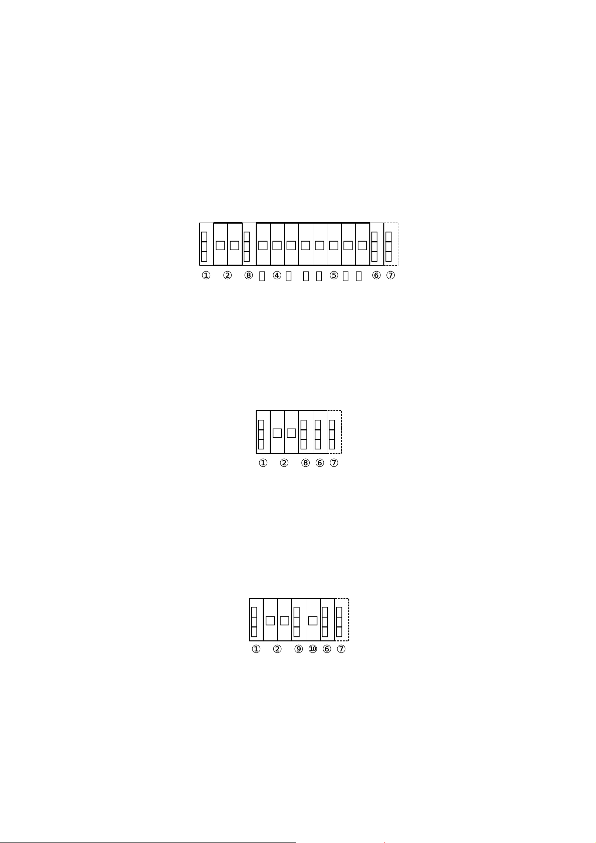
3.4 Composition of a response message (transmitted from this product to a
high-level computer)
n For codes ① through ⑩, see "3.5. Description of codes."
n For specific examples of request messages, see "4.1. Examples of communications to be read"
and "4.2. Examples of communications to be written."
3.4.1 Response message in response to a read request message
STX
①
Start code
ACK
□
□
□
②
⑧
|
Address
Acknowledge code
□
□
□
|
④
Identifier
|
□
□
□
□
|
|
⑤
|
Numerical data
End code
BCC
ETX
⑥
⑦
BCC data
3.4.2 Response message in response to a write/store request message
STX
①
Start code
3.4.3 Response message in the case of an error
STX
□
①
Start code
Address⑥End code
ACK
BCC
□
②
Address⑥End code
□
②
acknowledge code
ETX
□
⑦
⑧
BCC data
Acknowledge code
NAK
BCC
ETX
□
⑩
⑦
BCC data
⑨
Negative
Error code
10
Page 11

3.5 Description of codes
n The codes from ① STX, ② address to ⑩ ERR as indicated below are expressed in ASCII
codes.
n For the ASCII codes, see "9. Table of ASCII codes."
n For conversion to ASCII codes, see "4. Examples of TOHO communications."
① STX
This code is needed for the receiver to detect the top of the message. It is affixed to the top
of a character string to be sent.
② Address
This is the address of the party (this product) with whom a high-level computer
communicates. The address in the response message from this product indicates the sender
of the response message. Note that, when CH2 is used, two addresses are occupied. (Setting
ADR to 1 causes this product to occupy addresses 1 and 2.)
③ Contents requested
Enter a code R or W.
R: to read data from this product
W: to write or store data in this product
④ Identifier
An identifier is a classification code (identifier) for data to be read or written and expressed
in a three-digit alphanumerical ASCII code. See "10. Table of identifiers (codes)."
⑤ Numerical data
At the time of writing or reading, 5-digit numerical data can be written.
Example: The table below indicates the significances of 5-digit numerical data 00010.
Example Significance of the value
Proportional band (P) →1.0%
Data (PV), etc, whose decimal point can be shifted
When the decimal point setting (DP) is 0 10
When the decimal point setting (DP) is 0.1 1.0
If DP = 0.1, the numerical data "12000" means 1200.0. In the case of text data, it is "□□INP." (The □
is a space.)
⑥ ETX
This code is needed for the receiver to detect the end of a message. It is affixed to the end of
a character string to be sent (except for BCC).
⑦ BCC
This is a check code for error detection and is the exclusive OR (EX-OR) of all characters
from STX to ETX.
If the BCC check is set to "Disabled" in the communications settings in this product, this
code (BCC) will not be incorporated in the response message. See "2. Settings regarding
TOHO communications."
11
Page 12

⑧ ACK
It is an acknowledge code. If a message received by this product is error-free, this code will
be incorporated in the "response message" from this product and returned.
⑨ NAK
It is a negative acknowledge code. If a "request message" received by this product is
error-ridden, this code will be incorporated in the "response message" from this product and
returned.
If the "request message" received is error-ridden, the error contents (⑩ ERR type) will be
incorporated in the "response message" from this product, following NAK.
⑩ ERR type
If a "request message" received from this product is error-ridden, the error contents (either
of the numbers in the table below) will be incorporated in the "response message" from this
product, following "⑨ NAK."
The error number 0 is an instrument error (memory error or A/D conversion error). It will
be incorporated in the "response message" regardless of whether there is an error in the
"request message."
The error number 9 is an AT error. It will therefore be incorporated in the "response
message" regardless of whether there is an error in the "request message." Remove the
cause of the error immediately and start the AT again.
If there are two or more errors occurring at the same time, the largest error number will be
incorporated.
The table below indicates the error contents and classifications.
Error No.
0 Instrument error (memory error or A/D conversion error)
1 The numerical data deviated from the "range of settings designated specifically with setting
items."
2 The change of requested items is disabled or there are no items to be read.
3 An ASCII code other than the numerical data was specified in the field of numerical data.
An ASCII code other than numbers and "-" was specified in the field of codes.
4 Format error
5 BCC error
6 Overrun error
7 Framing error
8 Parity error
9 A PV error occurred during AT. Or AT will not end 3 hours later.
Error contents in the "request message" received by this product
12
Page 13

3.6 Communications precautions
3.6.1 Communications timing
Set a sufficient response delay to make sure that this product is switched over from transmission to
reception with regard to a high-level computer in using an RS-485.
See the figure in "3.1. Communications procedure" and "2.8. Setting a response delay."
3.6.2 Interval between requests
In transmitting a series of "request messages" from a high-level computer, allow for an interval of
1msec or more from the reception of a "response message" from this product to a next
transmission.
3.6.3 Response conditions
This product will not return a "response message" unless it receives a "request message" containing
an STX and ETX (BCC).
If, therefore, the "request message" is error-ridden, this product will not return a "response
message" (error reply) containing a NAK and ERR unless the conditions mentioned above are met.
Therefore transmit the necessary "request message" again if a "request message" is sent to the
high-level computer but the latter does not return a "response message" at the end of an appropriate
period.
The moment this product receives an STX, it clears all codes received before that.
3.6.4 Errors in address specification
This product will not respond to any "request message" that specifies an address other than that
specified for itself. If, therefore, the address portion of a "request message" is error-ridden, none of
the mobile units will return a "response message."
Therefore transmit the necessary "request message" again if a "request message" is sent to the
high-level computer but the latter does not return a "response message" at the end of an appropriate
period.
The moment this product receives an STX, it clears all codes received before that.
3.6.5 Number of digits in data and the decimal position
See "3.5. Description of codes, ⑤ Numerical data."
3.6.6 Operation after receiving a store request message
This product starts to store data after correctly receiving a store request message from a high-level
computer.
This product only stores data different from the contents of the EEPROM (data that is changed).
The time (TW) required for storing data is within 6 seconds.
This product transmits a storage-complete reply (ACK) when the data is stored.
This product will not guarantee that the data is stored if this product is turned off during a storage
operation. Do not turn off this product for 6 seconds after transmitting a store request message.
3.6.7 Operation after turning on the power
This product will not perform communications (no response) for about 4 seconds after it is turned
on. Allow for a delay until communications is started after this product is turned on.
13
Page 14

3.6.8 Storing data other than a store request message
Store all parameters in the EEPROM in either of the two cases described below, even if no store
request message is received.
1) If a parameter is changed by key operation
2) If auto-tuning is started and ends normally.
3.6.9 Changing the settings (SV or SV2) by communications during auto-tuning
Even if the settings (SV or SV2) used in control for auto-tuning are changed by communications,
the settings (SV or SV2) will not be changed until the auto-tuning ends.
14
Page 15

4. Examples of TOHO communications
4.1 Examples of communications to be read
Example: Request message: This requests this product set at address 27 to read the PV.
(High-level computer)
In response to that,
Response message: This returns PV data (00777).
Read request message (transmitted from the high-level computer)
STX
2
7
R
P
V
①
②
③
④
|
BCC
ETX
1
|
⑥
⑦
STX
①
Code Code, data ASCII code, note 2)
① Start code STX 02H
② Address 27 32H 37H
③ Request contents R (Read) 52H
④ Identifier, note 1) PV1 50H 56H 31H
⑤ Numerical data 00777 30H 30H 37H 37H 37H
⑥ End code ETX 03H
⑦ BCC data request 61H
response 02H
⑧ Acknowledge code ACK 06H
Note 1): See "10. Table of identifiers (codes)."
Note 2): For the ASCII codes, see "9. Table of ASCII codes."
ACK
2
7
P
V
1
0
0
7
7
②
⑧
|
④
|
|
15
|
⑤
|
BCC
ETX
7
⑥
⑦
|
Page 16

4.2 Examples of communications to be written
Example: Request message: This requests this product set at address 03 to set "the E1F setting to
(High-level computer) 011" (write 011).
(This sets the function in event 1 to the deviation upper and lower
limits + hold.)
In response to that,
Response message: This returns a notice that the request message has been received.
(This product)
*Check that it has been written by reading the data separately.
Write request message (transmitted from a high-level computer)
STX
0
3
W
E
1
F
0
0
0
1
①
②
③
|
④
|
|
|
⑤
|
BCC
ETX
1
⑥
⑦
|
STX
0
①
Code Code, data ASCII code, note 2)
① Start code STX 02H
② Address 03 30H 33H
③ Request contents W (Write) 57H
④ Identifier, note 1) E1F 41H 34H 46H
⑤ Numerical data 00011 30H 30H 30H 31H 31H
⑥ End code ETX 03H
⑦ BCC data request 57H
response 04H
⑧ Acknowledge code ACK 06H
Note 1): See "10. Table of identifiers (codes)."
Note 2): For the ASCII codes, see "9. Table of ASCII codes."
ACK
BCC
ETX
3
②
⑥⑦⑧
16
Page 17

5. Settings regarding MODBUS communications
5.1 Overview
Before communications is performed, initial settings must be made on this product. Enter such
settings with the keys on the front panel. To switch to a series of setting screens, take the steps
described below. For details, see the operation manual furnished with this product.
Power ON
Initial setting
Operation mode screen
MODE key at least 2 seconds
(Setting mode selection screen)
▲ ▼key
MODE key
MODE key
MODE key
MODE key
MODE key
MODE key
Select a communications setting mode
Set a communications protocol
Set a communications parameter
Set a communications speed
Set a communications address
Set a communications response delay
Set communications mode switchover
MODE key
When the settings are over, press the MODE key at least 2 seconds to go back to the operation mode.
The parameters indicated above are initial values.
17
Page 18

5.2 Setting a data length
5.3 Setting a stop bit length
5.4 Setting a parity
While in the "Set a communications parameter" screen on the preceding page, operate the ▲ and
▼ keys to make the settings.
The initial value is [ ].
Stop bit 1
Stop bit 2
No parity
Odd parity
Even parity
Data length, 7 bits
Data length, 8 bits
* The ASCII mode settings come only in three types: , , and .
The RTU mode settings come only in three types: , , and .
5.5 Setting a communications speed
While in the "Set a communications speed" screen on the preceding page, operate the ▲ and ▼
keys to make the settings.
The initial value is [ ].
1200bps
2400bps
4800bps
9600bps
19200bps
18
Page 19

5.6 Setting an address
While in the "Set a communications address" screen on the preceding page, operate the ▲ and ▼
keys to make the settings.
The initial value is •.
Setting range: 1 to 247 stations (It cannot be set to a 0.)
5.7 Setting a response delay
Set a time from the time when the high-level computer finished sending a "request message" until
the time when it delivers the line and enters an input state.
While in the "Set a response delay" on the preceding page, operate the ▲ and ▼ keys to make the
settings.
The initial value is 0.
Setting range: 0 to 250ms
* If the response delay is set to a short setting, the communications may not be conducted normally.
* In a real operation, the processing time for this product will be added, in addition to the response
delay.
5.8 Switching communications mode
While in the "Set communications mode switchover" screen on the preceding page, operate the ▲
and ▼ keys to make the settings.
Read only
Read and write
19
Page 20

6. MODBUS communications control
6.1 Communications procedure
This product returns a "response message" in response to a "request message" from a high-level
computer. It therefore does not initiate a transmission.
Transmitted by a high-
level computer
High-level computer
This product
See "5.7. Set a response delay."
See "6.6.1. Communications timing."
Request message
Response delay:
0-250ms
Transmitted by this
product
Request message
6.2 Message types
n Messages are roughly divided into the following types:
Request message (transmitted
from a high-level computer)
Read request message
Transmitted by a high-
level computer
Request message
1ms or more, or 3.5 character seconds or more,
whichever the longer
See 6.6.2. "Interval between requests."
Response message (transmitted
from this product)
Receipt acknowledgement and data
response
Transmitted by this
product
Request message
Write complete response
Write request message
Reception error and error description
response
Store request message
: Response when a normal "request message" is received
: When a received "request message" contains an error
Store complete response
n In RTU codes, the data is binary.
n In ASCII codes, all codes are expressed in ASCII codes.
n In assembling a program for a high-level computer, see "10. Table of identifiers (codes)" and "9.
Table of ASCII codes" at the end of the book.
20
Page 21

6.3 Composition of an RTU request message (transmitted from a high-level
computer to this product)
n For codes a) through i), see "6.5. Description of RTU codes."
6.3.1 Composition of a read request message
a) Slave address 1BH
b) Function code 03H
c) Register address
d) Number of registers
e) CRC-16
High level
Low level
High level
Low level
High level
Low level
6.3.2 Composition of a write request message
Multiple
a) Slave address 03H
b) Function code 10H
c) Register address
d) Number of registers
f) Number of data items 04H Number of registers × 2
Data for the first register
(a low-level word)
g)
Data for the first register + 1
(a high-level word)
e) CRC-16
High level
Low level
High level
Low level
High level
Low level
High level
Low level
High level
Low level
Single
a) Slave address 03H
b) Function code 06H
c) Register address
Data for the first register
g)
(a low-level word)
e) CRC-16
High level
Low level
High level
Low level
High level
Low level
21
00H
00H
00H
02H
C6H
31H
00H
C0H
00H
02H
00H ③
6FH ④
00H ①
00H ②
C4H
5AH
00H
C0H
00H ①
6FH ②
C4H
5AH
First register address
2 to 100 (even number only)
First register address
Fixed at 2
When writing ①, ②, ③, and
④ H in the data, write them in
the order described on the
left-hand side. (① represents 1
byte.)
First register address
When writing ① and ② H in
the data, write them in the order
described on the left-hand side.
(① represents 1 byte.)
Page 22

6.3.3 Composition of a store request message
a) Slave address 03H
b) Function code 10H
c) Register address
d) Number of registers
f) Number of data items 04H Number of registers × 2
Data for the first register
(a low-level word)
g)
Data for the first register + 1
(a high-level word)
e) CRC-16
High level
Low level
High level
Low level
High level
Low level
High level
Low level
High level
Low level
02H
0EH
00H
02H
00H
00H
00H
00H
60H
FBH
First register address
Fixed at 2
The data about the storage of settings
is arbitrary.
6.4 Composition of an RTU response message (transmitted from this product
to a high-level computer)
n For codes a) through h), see "6.5. Description of RTU codes."
6.4.1 Response message for a read request message
a) Slave address 1BH
b) Function code 03H
d) Number of data items 04H Number of registers × 2
Data for the first register
(a low-level word)
g)
Data for the first register + 1
(a high-level word)
e) CRC-16
High level
Low level
High level
Low level
High level
Low level
6.4.2 Response message for a write/store request message
Multiple
a) Slave address 03H
b) Function code 10H
c) Register address
d) Number of registers
e) CRC-16
High level
Low level
High level
Low level
High level
Low level
22
03H
09H
00H
00H
91H
B4H
00H
00H
00H
02H
40H
2AH
First register address
Fixed at 2
Page 23

Single
a) Slave address 03H
b) Function code 06H
c) Register address
Data for the first register
g)
(a low-level word)
e) CRC-16
High level
Low level
High level
Low level
High level
Low level
00H
C0H
00H
6FH
C4H
5AH
First register address
6.4.3 Response message in the case of an error
a) Slave address 1BH
b) Function code 83H
h) Error code 02H
e) CRC-16
High level
Low level
E1H
36H
← In the case of an error, the function
code for the request message +
80H is entered.
6.5 Description of RTU codes
n The codes from a) slave address to b) function code to h) error code shown below are expressed
in 8-bit binary numbers.
a) Slave address
This is the address of the party (this product) with which the high-level computer
communicates. The address in the response message from this product represents the source
of the response message. Note that, when CH2 is used, 2 addresses are occupied. (When the
ADR is set to 1, addresses 1 and 2 are occupied.)
b) Function code
Enter a code 03H, 06H, or 10H.
03H: To read data from this product
06H: To write or store data in this product (multiple)
10H: To write or store data in this product (single)
c) Register address
The locations of the data to be read or that to be written are specified in 2 bytes.
The data is written in the holding register.
For the addresses of the commands, see "10. Table of identifiers (codes)."
d) Number of registers
This specifies the number of registers to be written in. Since this product has a fixed number
of registers (which is 2), specify 0002H.
23
Page 24

e) CRC-16
This error check code is for detecting message errors. This transmits a CRC-16 (tour
redundancy code).
The multinomial for generating a CRC-16 used in this product is X16+X15+X2+1.
To learn how to calculate the CRC-16, see "6.7. Example of CRC-16 calculations."
To affix an error code at the end of the message, affix the low-level byte first, then the
high-level byte of the CRC.
f) Number of data
This specifies the number of registers to be read and written x 2. Since the number of
registered in this product is fixed at 2, specify 04H here.
g) Data portion
This specifies data to be written in the register. The data is fixed at 4 bytes. This product
will write data without the decimal point.
Example: In the case of numerical data
Example Significance of the value
Proportional band (P) = 1.0 % 0000000AH
PV = 1200.0°C 00002EE0H
SV = -10.00°C FFFFFC18H
In the case of text data, write the ASCII code "□INP" (□ is a space): 2049E50H.
h) Error code
If a message from a high-level computer is error-ridden, it will be incorporated in the
"response message" from this product and returned.
The error number "04" is an instrument error (memory error or A/D conversion error, AT
error). It will be incorporated in the "response message" regardless of whether there is an
error in the "request message."
If there are two or more errors occurring at the same time, the largest error number will be
incorporated.
The table below indicates the error contents and classifications.
Error No. Error contents in the "request message" received by this product
01 Received an unsupported function code.
02 Received an address other than the specified one.
03 The numerical data deviated from the "range of settings designated specifically with
04 Instrument error (memory error or A/D conversion error, AT error)
setting items."
24
Page 25

6.6 Precautions on RTU communications
6.6.1 Communications timing
Set a sufficient response delay to make sure that this product is switched over from transmission to
reception with regard to a high-level computer in using an RS-485.
See the figure in "5.1. Overview" and "5.7. Setting a response delay."
3.6.2 Interval between requests
In transmitting a series of "request messages" from a high-level computer, allow for an interval of
1msec or more or 3.5 character minutes, whichever the longer, from the reception of a "response
message" from this product to a next transmission.
6.6.3 Response conditions
If there is a time interval of 3.5 characters or more between data items constituting a "request
message," this product cannot recognize it as a "request message." It will therefore not return a
"response message." If, therefore, the "request message" contains an error, this product will not
return a "response message" (error reply) containing an ERR unless the above conditions are met.
Therefore transmit the necessary "request message" again if a "request message" is sent to the
high-level computer but the latter does not return a "response message" at the end of an appropriate
period.
The moment a period of 3.5 characters or more has elapsed, it clears all codes received before that.
6.6.4 Errors in address specification
This product will not respond to any "request message" that specifies an address other than that
specified for itself. If, therefore, the address portion of a "request message" is error-ridden, none of
the mobile units will return a "response message."
Therefore transmit the necessary "request message" again if a "request message" is sent to the
high-level computer but the latter does not return a "response message" at the end of an appropriate
period.
6.6.5 Number of digits in data and the decimal position
See "6.5. Description of RTU codes, g) Data portion."
6.6.6 Operation after receiving a store request message
This product starts to store data after correctly receiving a store request message from a high-level
computer.
This product only stores data different from the contents of the EEPROM (data that is changed).
The time (TW) required for storing data is within 6 seconds.
This product transmits a storage-complete reply after the data is stored.
This product will not guarantee that the data is stored if this product is turned off during a storage
operation. Do not turn off this product for 6 seconds after transmitting a store request message.
6.6.7 Operation after turning on the power
This product will not perform communications (no response) for about 4 seconds after it is turned
on. Allow for a delay until communications is started after this product is turned on.
25
Page 26

6.6.8 Changing the settings (SV or SV2) by communications during auto-tuning
Even if the settings (SV or SV2) used in control for auto-tuning are changed by communications,
the changes (SV or SV2) will not be changed until the auto-tuning ends.
6.7 Example of CRC-16 calculations
Following is an example of calculating CRC-16 with VisualBasic6.0.
Variables are declared as shown below.
VisualBasic6.0 cannot use code-free variables. It therefore uses code-equipped 16-bit integer
variables as data. Similarly, the CRC calculation results are entered into code-equipped 32-bit
integer variables.
Dim CRC As Long
Dim i, j, arry_count As Integer
Dim c_next, c_carry As LongDim crc_arry(64) As Integer
Then enter calculable data into the crc_arry(), and enter the number of data items into the arry_count.
After that, run the following program to cause the calculation results to enter the CRC.
i = 0
CRC = 65535
For i = 0 To arry_count
c_next = crc_arry(i)
CRC = (CRC Xor c_next) And 65535
For j = 0 To 7
c_carry = CRC And 1
CRC = CRC ¥ 2
If c_carry Then
CRC = (CRC Xor &HA001) And 65535
End If
Next
Next
To affix an error code to the end of the message, affix first the low-level byte and then the high-level
byte of the CRC.
26
Page 27

6.8 Composition of an ASCII request message (transmitted from a high-level
computer to this product)
n For the codes a) through g), see "6.10. Description of ASCII codes."
6.8.1 Composition of a read request message
a) Start code “:”
b) Slave address “1” , “B”
c) Function code “0” , “3”
d) Register address
e) Number of registers
f) LRC “E” , “0”
g) End code CR, LF
6.8.2 Composition of a write request message
a) Start code “:”
b) Slave address “0” , “3”
c) Function code “1” , “0”
d) Register address
e) Number of registers
h) Number of data items “0” , “4” Number of registers × 2
Data for the first register
(a low-level word)
i)
Data for the first register + 1
(a high-level word)
f) LRC “E” , “0”
g) End code CR, LF
High level “0” , “0”
Low level “0” , “0”
High level “0” , “0”
Low level “0” , “2”
High level “0” , “0”
Low level “C” , “0”
High level “0” , “0”
Low level “0” , “2”
High level “0” , “0” ③
Low level “6” , “F” ④
High level “0” , “0” ①
Low level “0” , “0” ②
First register address
2 to 100 (even number only)
27
First register address
Fixed at 2
When writing ①, ②, ③, and
④ H in the data, write them in
the order described on the
left-hand side. (① represents 1
byte.)
Page 28

6.8.3 Composition of a store request message
a) Start code “:”
b) Slave address “0” , “3”
c) Function code “1” , “0”
d) Register address
e) Number of registers
h) Number of data items “0” , “4” Number of registers × 2
Data for the first register
(a low-level word)
i)
Data for the first register + 1
(a high-level word)
f) LRC “D” , “7”
g) End code CR, LF
High level “0” , “2”
Low level “0” , “E”
High level “0” , “0”
Low level “0” , “2”
High level “0” , “0”
Low level “0” , “0”
High level “0” , “0”
Low level “0” , “0”
First register address
Fixed at 2
The data about the storage of settings
is arbitrary.
6.9 Composition of ASCII response messages (transmitted from this product
to a high-level computer)
n For the codes a) through g), see "6.10. Description of ASCII codes."
6.9.1 Response message for a read request message
a) Start code “:”
b) Slave address “1” , “B”
c) Function code “0” , “3”
h) Number of data items “0” , “4” Number of regi sters × 2
Data for the first register
(a low-level word)
i)
Data for the first register + 1
(a high-level word)
f) LRC “D” , “2”
g) End code CR, LF
High level “0” , “3” ③
Low level “0” , “9” ④
High level “0” , “0” ①
Low level “0” , “0” ②
28
When writing ①, ②, ③, and
④ H in the data, write them in
the order described on the
left-hand side. (① represents 1
byte.)
Page 29

6.9.2 Response message for a write/store request message
a) Start code “:”
b) Slave address “0” , “3”
c) Function code “1” , “0”
d) Register address
e) Number of registers
f) LRC “E” , “B”
g) End code CR, LF
High level “0” , “0”
Low level “0” , “0”
High level “0” , “0”
Low level “0” , “2”
First register address
Fixed at 2
6.9.3 Response message in the case of an error
a) Start code “:”
b) Slave address “1” , “B”
h) Function code “8” , “3”
j) Error code “0” , “2”
f) LRC “6” , “0”
g) End code CR, LF
← In the case of an error, the function
code for the request message +
80H is entered.
29
Page 30

6.10 Description of ASCII codes
n The codes from a) start code to b) slave address to j) error type described below are expressed
in ASCII codes.
n For ASCII codes, see "9. Table of ASCII codes."
n For converting to ASCII codes, see 6.8 and 6.9 "Message composition."
a) Start code
The receiver side is the code required for detecting the top of the message. It is affixed to
the top of a character string to be transmitted.
b) Slave address
This is the address of the party (this product) with which the high-level computer
communicates. The address in the response message from this product represents the
source of the response message. Note that, when CH2 is used, 2 addresses are occupied.
(When the ADR is set to 1, addresses 1 and 2 are occupied.)
c) Function code
Enter a code 03H or 10H.
03H: To read data from this product
10H: To write or store data in this product
d) Number of registers
This specifies the number of registers to be written in. Since this product has a fixed
number of registers (which is 2), specify 0002H.
e) Register address
The locations of the data to be read or that to be written are specified in 2 bytes.
For the addresses of the commands, see "10. Table of identifiers (codes)."
f) LRC
LRC is an error check code for detecting message errors. An LRC is transmitted. The LRC
used in this product is the 2-complement of the sum of the data portions without a carry,
except for the start code and end code of the message.
The parts of the data portions expressed as a "1" and "B" are considered as "1BH."
To learn how to calculate the LRC, see "6.12. Example of LRC calculations."
If 12H is calculated as an error code, affix a "1" or "2" at the end of the message.
g) End code
This code is required for the receiver to detect the end of a message. Affix CR (0DH) and
LF (0AH) at the end of a character string to be transmitted.
h) Number of data
This specifies the number of registers to be read and written x 2. Since the number of
registered in this product is fixed at 2, specify 04H here.
30
Page 31

i) Data portion
This specifies data to be written in the register. The data is fixed at 4 bytes. This product
will write data without the decimal point.
Example: In the case of numerical data
Example Significance of the value
Proportional band (P) = 1.0 % 0000000AH
PV = 1200.0°C 00002EE0H
SV = -10.00°C FFFFFC18H
In the case of text data, write the ASCII code "□INP" (□ is a space): 2049E50H.
j) Error code
If a message from a high-level computer is error-ridden, it will be incorporated in the
"response message" from this product and returned.
The error number "04" is an instrument error (memory error or A/D conversion error, AT
error). It will be incorporated in the "response message" regardless of whether there is an
error in the "request message."
If there are two or more errors occurring at the same time, the largest error number will be
incorporated.
The table below indicates the error contents and classifications.
Error No. Error contents in the "request message" received by this product
01 Received an unsupported function code.
02 Received an address other than the specified one.
03 The numerical data deviated from the "range of settings designated specifically with
04 Instrument error (memory error or A/D conversion error, AT error)
setting items."
31
Page 32

6.11 Precautions on ASCII communications
6.11.1 Communications timing
Set a sufficient response delay to make sure that this product is switched over from transmission
to reception with regard to a high-level computer in using an RS-485.
See the figure in "5.1. Overview" and "5.7. Setting a response delay."
6.11.2 Interval between requests
In transmitting a series of "request messages" from a high-level computer, allow for an interval of
1msec or more or 3.5 character minutes, whichever the longer, from the reception of a "response
message" from this product to a next transmission.
6.11.3 Response conditions
This product will not return a "response message" unless the "request message" contains a start
code and end code.
If, therefore, the "request message" contains an error, this product will not return a "response
message" (error reply) containing an error code unless the above conditions are met.
Therefore transmit the necessary "request message" again if a "request message" is sent to the
high-level computer but the latter does not return a "response message" at the end of an
appropriate period.
The moment a start code is received, this product clears all codes received before that.
6.11.4 Errors in address specification
This product will not respond to any "request message" that specifies an address other than that
specified for itself. If, therefore, the address portion of a "request message" is error-ridden, none
of the mobile units will return a "response message."
Therefore transmit the necessary "request message" again if a "request message" is sent to the
high-level computer but the latter does not return a "response message" at the end of an
appropriate period.
The moment a start is received, this product clears all codes received before that.
6.11.5 Number of digits in data and the decimal position
See "6.10. Description of ASCII codes, i) Data portion."
6.11.6 Operation after receiving a store request message
This product starts to store data after correctly receiving a store request message from a
high-level computer.
This product only stores data different from the contents of the EEPROM (data that is changed).
The time (TW) required for storing data is within 6 seconds.
This product transmits a storage-complete reply after the data is stored.
This product will not guarantee that the data is stored if this product is turned off during a storage
operation. Do not turn off this product for 6 seconds after transmitting a store request message.
6.11.7 Operation after turning on the power
This product will not perform communications (no response) for about 4 seconds after it is turned
on. Allow for a delay until communications is started after this product is turned on.
32
Page 33

6.11.8 Changing the settings (SV or SV2) by communications during auto-tuning
Even if the settings (SV or SV2) used in control for auto-tuning are changed by communications,
the changes (SV or SV2) will not be changed until the auto-tuning ends.
6.12 Example of LRC calculations
Following is an example of calculating LRC with VisualBasic6.0.
Variables are declared as shown below.
VisualBasic6.0 cannot use code-free variables. It therefore uses code-equipped 16-bit integer
variables as data. Similarly, the LRC calculation results are entered into code-equipped 16-bit
integer variables.
Dim LRC As Integer
Dim i, arry_count As Integer
Dim lrc_arry(128) As Integer
Then enter calculable data into the 1rc_arry(), and enter the number of data items into the
arry_count. After that, run the following program to cause the calculation results to enter the LRC.
For i = 0 To arry_count
LRC = (LRC + lrc_arry(i)) And &HFF
Next
LRC = ((Not LRC) + 1) And &HFF
If the error code is calculated as 12H as an example, affix a "1" or "2" at the end of the message.
33
Page 34

7. Specifications
7.1 Communications standard category: Compliant with EIA standard RS-485
7.2 Communications specifications
7.2.1 Communications system
Network:...................................For RS-485, multi-drop system (up to 1 pair, 31 stations)
Direction of information:..........Half duplex
Synchronization system:...........Asynchronous
Transmission code:...................ASCII, 7/8 bit code, except for BBC data
(highest-level bit = 0 in 8-bit code)
7.2.2 Interface system
Signal line:................................2 lines for transmission and reception
Communications speed:............One speed is selected from 1,200, 4,800, 9,600, and 19,200 bps
and this product is set to it.
Communications distance:........500m maximum
Provided that it varies somewhat depending on the cable and other
ambient conditions.
7.2.3 TOHO communications characters
Start bit length: .........................Fixed at 1 bit
Stop bit length:..........................Either 1 or 2 bit is selected and this product is set to it.
Data length:...............................Either 7 or 8 bit is selected and this product is set to it.
Parity: .......................................No. Either odd or even is selected and this product is set to it.
BCC check:...............................Yes or no is selected and this product is set to it.
Communications address:.........1-99
7.2.4 MODBUS communications (RTU) characters
Start bit length: .........................Fixed at 1 bit
Stop bit length:..........................Either 1 or 2 bit is selected and this product is set to it. (If
parity-equipped, fixed at 1 bit.)
Data length:...............................Fixed at 8 bit.
Parity: .......................................No. Either odd or even is selected and this product is set to it.
CRC-16 check: .........................Fixed at yes.
Communications address:.........1-247
7.2.5 MODBUS communications (ASCII) characters
Start bit length: .........................Fixed at 1 bit
Stop bit length:..........................Either 1 or 2 bit is selected and this product is set to it. (If
parity-equipped, fixed at 1 bit.)
Data length:...............................Fixed at 7 bit.
Parity: .......................................No. Either odd or even is selected and this product is set to it.
LRC check:...............................Fixed at yes.
Communications address:.........1-247
7.2.6 MODBUS communications (ASCII/RTU) function codes
03H (reading the contents of the holding register)
10H (writing the contents of two or more holding registers)
34
Page 35

8. Connections
8.1 Connections for the RS-485
High-level computer
(parent station)
This product
(mobile unit)
T/R(A)
T/R(B)
T/R(A)
T/R(B)
T/R(A)
T/R(B)
T/R(A)
T/R(B)
Communications is such that the connections can be made with the connectors on the sides.
Install an end of line resistor at both of the farthest devices in the parent station and the mobile unit.
For a resistance value, use one that matches the characteristic impedance of the cable. Provided that
the synthesis is set to at least 75Ω.
35
Page 36

9. Table of ASCII codes
ASCII code 00H 01H 02H 03H 04H 05H 06H 07H
NUL SOH STX ETX EOT ENQ ACK BEL
ASCII code 08H 09H 0AH 0BH 0CH 0DH 0EH 0FH
BS HT LF VT FF CR SO SI
ASCII code 10H 11H 12H 13H 14H 15H 16H 17H
DLE DC1 DC2 DC3 DC4 NAK SYM ETB
ASCII code 18H 19H 1AH 1BH 1CH 1DH 1EH 1FH
CAN EM SUB ESC FS GS RS US
ASCII code 20H 21H 22H 23H 24H 25H 26H 27H
スペース ! # $ % &
ASCII code 28H 29H 2AH 2BH 2CH 2DH 2EH 2FH
( ) * + , − . /
ASCII code 30H 31H 32H 33H 34H 35H 36H 37H
0 1 2 3 4 5 6 7
ASCII code 38H 39H 3AH 3BH 3CH 3DH 3EH 3FH
8 9 : ; < = > ?
ASCII code 40H 41H 42H 43H 44H 45H 46H 47H
@ A B C D E F G
ASCII code 48H 49H 4AH 4BH 4CH 4DH 4EH 4FH
H I J K L M N O
ASCII code 50H 51H 52H 53H 54H 55H 56H 57H
P Q R S T U V W
ASCII code 58H 59H 5AH 5BH 5CH 5DH 5EH 5FH
X Y Z [ ¥ ] ^ _
ASCII code 60H 61H 62H 63H 64H 65H 66H 67H
a b c d e f g
ASCII code 68H 69H 6AH 6BH 6CH 6DH 6EH 6FH
h i j k l m n o
ASCII code 70H 71H 72H 73H 74H 75H 76H 77H
p q r s t u v w
ASCII code 78H 79H 7AH 7BH 7CH 7DH 7EH 7FH
x y z { | } 〜 DEL
36
Page 37

level W
level W
level W
10. Table of identifiers (codes)
MODBUS ADR Operation mode
Low-
40000 40001 PV1 Measurement R
40002 40003 SV1 Control setting R/W R/W of the setting (SV)
MODBUS ADR Initial setting mode
Low-
40004 40005 INP Set an input type R/W 000??
40006 40007 PVG Set a PV corrected gain R/W
40008 40009 PVS Set a PV corrected zero point R/W
40010 40011 PDF Set a PV filter R/W
40012 40013 □DP
40014 40015 □FU Set a function key function R/W
40016 40017 LOC Set a key lock R/W
MODBUS ADR Control setting mode
Low-
40018 40019 SLH Set an SV limiter upper limit R/W
40020 40021 SLL Set an SV limiter lower limit R/W
40022 40023 □MD
40024 40025 CNT Set a control type R/W
40026 40027 DIR Set positive/reverse operation switchover R/W
40028 40029 MV1 Amount of output operation R/W W possible during manual control
40030 40031 TUN Set a tuning type R/W
40032 40033 ATG Set an AT factor R/W
40034 40035 ATC Set an AT sensitivity R/W
40036 40037 □P1 Set a proportional band R/W
40038 40039 □I1 Set an integral time R/W
40040 40041 □D1 Set a derivative time R/W
40042 40043 □T1 Set a proportional frequency R/W
40044 40045 ARW Anti-reset windup R/W
40046 40047 MH1 Set an amount-of-operation limiter upper limit R/W
40048 40049 ML1 Set an amount-of-operation limiter lower limit R/W
40050 40051 PBB Manual reset R/W
40052 40053 MV2 Amount of cooling output operation R/W W possible during manual control
40054 40055 □P2 Set a cooling power proportional band R/W
40056 40057 □T2 Set a cooling output proportional cycle R/W
40058 40059 MH2 Set a cooling output amount-of-operation limiter upper limit R/W
40060 40061 ML2 Set a cooling output amount-of-operation limiter lower limit R/W
40062 40063 □C1 Set a (heating output) control sensitivity R/W
40064 40065 □C2 Set a cooling output control sensitivity R/W
40066 40067 CP1 Set an off-point position R/W
40068 40069 CP2 Set a cooling output off-point position R/W
40070 40071 □DB Set a dead band R/W
High-
level W
High-
level W
High-
level W
Iden-
tifier
Iden-
tifier
Iden-
tifier
Character
Character
Character
Name R/W
Use it as a monitor for measurements (PV).
When overscale: HHHH
When underscale: LLLL
Name R/W
No decimal point : 00000
Set a decimal position R/W
Name R/W
Set control mode R/W
1 decimal place : 00001
2 decimal place : 00002
3 decimal place : 00003
37
Description
Description
Description
Control execution : 00000
Manual control : 00001
Control stop : 00002
Auto-tuning in progress : 00003
Page 38

level W
level W
level W
level W
MODBUS ADR Event setting mode
Low-
40072 40073 E1F
40074 40075 E1H
40076 40077 E1L
40078 40079 E1C
40080 40081 E1T
40082 40083 E1B
40084 40085 E1P
40086 40087 CM1
40088 40089 CT1
High-
level W
Iden-
Character
tifier
Set an event output function
Set an event output upper limit
Set an event output lower limit
Set an event output sensitivity
Set an event output delay timer
Set an event output special function
Set an event output polarity
CT monitor
Set a CT abnormal current
Name R/W
Description
R/W
R/W
R/W
R/W
R/W
R/W
R/W
R
R/W
MODBUS ADR Timer setting mode
Low-
40090 40091 TMO
40092 40093 TMF
40094 40095 H/M
40096 40097 TSV
40098 40099 TIM
40100 40101 TIA
High-
level W
Iden-
Character
tifier
Set a timer output destination
Set a timer function
Set a timer unit
Set a timer SV start tolerance
Set a timer time
Set a timer remaining time
Name R/W
R/W
R/W
R/W
R/W
R/W
R/W
Description
MODBUS ADR DI setting mode
Low-
40102 40103 DIF
40104 40105 DIP
40106 40107 SV2
40108 40109 SV2
High-
level W
Iden-
Character
tifier
Set a DI function
Set a DI polarity
Set a CH1 SV2
Set a CH2 SV2
Name R/W
R/W
R/W
R/W
R/W
Description
MODBUS ADR Communications setting mode
Low-
40110 40111 PRT
40112 40113 COM
40114 40115 BPS
40116 40117 ADR
40118 40119 AWT
40120 40121 MOD
High-
level W
Iden-
Character
tifier
Set a communications protocol
Set a communications parameter
Set a communications speed
Set a communications address
Set a communications response delay
Set communications mode switchover R/W
Name R/W
Description
R/W
R/W Example: □B8N2
R/W Example: 00096 (if 9600 bps)
R/W
R/W
RO:00000
RW:00001
38
Page 39

level W
MODBUS ADR Screen-less commands
Low-
40122 40123 TST Timer start stop R/W
40124 40125 OM1 Output monitor R
40126 40127 EM1 DI monitor R
40128 40129 □AT Start/release AT R/W
40130 40131 STR Store data W Store data
High-
level W
Iden-
tifier
Character
Name R/W
Description
R of the output monito
①②③④⑤
⑤:Control output (1:ON 0:OFF)
④:Cooling output (1:ON 0:OFF)
③:Event output (1:ON 0:OFF)
R of DI monitor
①②③④⑤
⑤:DI (1: ON 0: OFF)
Read/write AT start/release
Start : 00001
Release : 00000
Reading during startup causes this product to
replay with 00001.
MODBUS ADR Identifiers used only in blind setting
Low-
level W
40132 40133 001 SET1 L/B
40134 40135 002 SET2 L/B
40136 40137 003 SET3 L/B
40138 40139 004 SET4 L/B
40140 40141 005 SET5 L/B
40142 40143 006 SET6 L/B
High-
level W
Iden-
tifier
Character
Name R/W
Description
Blinding enabled : 00000
Blinding disabled 00001
39
Page 40

TOHO ELECTRONICS INC.
Head office: 1-13-21, Tanashioda, Sagamihara Kanagawa 229-1125 Japan.
Phone: +81-42-777-3311 Fax: +81-42-777-3751
40 47-9927
 Loading...