


TOHO ELECTRONICS INC.
Program Controller TTM-P4/P9 Series
Instruction Manual
Thank you for purchasing our Program Controller TTM-P4/P9 Series. Please read this Instruction Manual carefully to use the product correctly. TTM-P4/P9 Series is a simplified program controller which enables program operation of up to 64 patterns x steps.
|
Contents |
|
1. |
Cautions on Use ................................................................................ |
1 |
2. |
Name and Size of Each Part.............................................................. |
2 |
3. |
Wiring................................................................................................ |
3 |
4. |
Terms and Functional Description .................................................... |
4 |
5. |
Before Program Operation ................................................................ |
6 |
6. |
Operation Flow and Parameter Description ...................................... |
7 |
7. |
Setting and Display Ranges............................................................. |
14 |
8. |
List of Types.................................................................................... |
14 |
9. |
Specifications and Rating................................................................ |
15 |
10. |
Maintenance and Inspection............................................................ |
16 |

1. Cautions on Use
For safety purpose, following symbols are used in this manual.
|
|
The case that a user may receive fatal damage, electric shock, or severe burn injury when |
|
Warning |
|
|
|
the product is incorrectly used. |
|
|
|
|
Caution |
The case that a user may receive minor damage or the equipment may get damage. |
|
|
|
|
|
|
|
|
|
|
Warning |
Verify correct wiring before turning on electricity since incorrect wiring may cause an |
|
|
equipment failure or a fire. Modification of this equipment may cause malfunctioning or |
|
|
a fire. Do not add modification on this equipment. |
|
|
Wiring: Do not use empty terminals for irrelevant purposes. |
|
Caution |
|
|
Operation: Do not use a sharp-pointed tool for operating keys. |
|
|
|
|
|
|
|
-Hand over this operation manual to a person who actually operates the product.
-Do not reprint or duplicate this manual without permission.
-Content of this manual may be subject to modification without prior notice.
-We are not liable for any faults arising from misuse of the product.
Verification of the product 1) Verification of the model:
Refer the model name printed in the packing box to the order sheet.
2) Verification of accessories: |
|
Instruction Manual (this manual)....................................... |
1 copy |
Mounting attachment ......................................................... |
1 pc (for TTM-P4) |
Mounting metal instrument................................................ |
1 set (for TTM-P9) |
3) Model |
|
TTM-P4-0-R (relay output with optional ABE) |
|
TTM-P4-0-P (SSR output with optional ABE) |
|
TTM-P9-0-R (relay output with optional ABE) |
|
TTM-P9-0-P (SSR output with optional ABE) |
|
Prior to control operation
-Non-volatile memory is used for storing settings, which stays in the storage even when the power is cut.
-Three thermocouple types (K, J, and R) are provided for this product.
When you use the product, please match the thermocouple type with product setting.
1

2. Name and Size of Each Part
2.1 Name of each part
LED Lamp
RUN: |
Lights during operation mode |
OUT: |
Lights as synchronized with main control output. |
|
For continuous proportional control, blinks depending |
|
on the volume of operation. |
SET: |
Lights during parameter setting. |
AL: |
Lights during alarm output. |
Operation Key
RUN/RESET key: RUN/RESET operation key
PATT./STEP key: PATTERN/STEP operation key
key: |
Setting value and parameter change key |
key: |
Setting value and parameter change key |
For the details of operation, see "6. Operation Flow and Parameter Description."
2.2 External dimensions and panel cut size
60 or more
Panel cut size
When one panel is mounted
Panel cut size
When n panels are mounted
When one panel is mounted
120 or more
When n panels are mounted
2

3.Wiring
3.1TTM-P4 series
|
|
|
|
|
|
Operation signal |
|
|
|
|
|
|
|
|
Output |
|
|
|
|
|
|
|
|
|
Reserved |
|
|
|
SSR drive |
Relay contact |
|
Time signal output/ |
|||
|
|
Reserved |
alarm |
|||||
|
|
|
|
|
|
|||
|
|
|
|
|
|
|
|
|
|
|
Control output |
|
Reserved |
|
|||
|
|
|
|
|
|
|
|
|
|
|
Power supply voltage |
|
Thermocouple input (K/J/R) |
||||
|
|
DI |
|
|||||
|
|
100 to 240VAC ± 10% |
|
|||||
|
|
|
|
|
|
|
(external input) |
Reserved |
|
|
|
|
|
|
|
|
|
3.2 TTM-P9 series |
|
|
|
|||||
|
|
|
|
|
|
|
DI |
|
|
|
|
|
|
|
|
(external input) |
|
|
|
Thermocouple input (K/J/R) |
Reserved |
|
||||
|
|
|
|
|
|
|
|
|
|
|
|
|
|
|
|
Reserved |
|
|
|
Time signal output/alarm |
Reserved |
|
||||
|
|
|
|
|
|
Operation |
|
|
|
|
|
|
|
|
|
|
|
|
|
|
|
|
|
signal |
Reserved |
|
|
|
|
|
|
|
Output |
|
|
|
|
|
|
|
|
|
|
|
|
|
SSR drive |
Relay contact |
Reserved |
|
|||
|
|
|
|
|
|
|
|
|
|
Control output |
|
|
Reserved |
|
|||
|
|
|
|
|
|
|
|
|
|
|
|
|
|
|
|
Reserved |
|
|
|
Power supply voltage |
|
|
||||
|
|
100 to 240VAC ± 10% |
Reserved |
|
||||
3.3 Caution on wiring |
|
|
|
|||||
|
|
|
|
|
Before wiring, be sure to turn off the power supply. Otherwise, you may get an electric |
|||
|
|
Warning |
|
|
||||
|
|
|
|
shock. |
|
|
|
|
|
|
|
|
|
|
|
|
|
|
|
|
|
|
|
|
|
|
|
|
|
|
|
This equipment does not execute control operation for about 4 seconds after the power is |
|||
|
|
Caution |
|
|
||||
|
|
|
|
turned on. (Control output does not work. during the period) |
|
|||
|
|
|
|
|
|
|||
|
|
|
|
|
Pay attention when you use this equipment for interlock circuit. |
|
||
|
|
|
|
|
Confirm the wirings of the input terminal, power terminal, and optional terminal by reading |
|||
|
|
|
|
|
the label at the side of the equipment. |
|
|
|
-Use crimping terminals matching to M3.5 screws. Also, when you wire to the central terminals, tighten the wire directly.
-As for wire rods to be used for connecting this equipment with a thermocouple, use a specific compensating lead wire or wire itself.
-When you use this equipment near the source of noise, use a shielded wire. Also, do not wire the input/output line in the same duct or wire conduit.
-Leave the input/output signal line more than 50 cm away from the power and load lines.
3
4.Terms and Functional Description
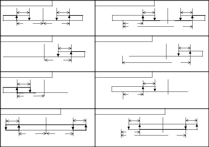
4.1Event output
1. Deviation upper/lower limit |
|
5. Absolute value upper/lower limit |
|
||
ALd |
|
ALd |
|
ALd |
ALd |
ALL |
|
ALH |
|
ALL |
ALH |
|
SV |
|
|
|
|
2. Deviation upper limit |
|
|
6. Absolute value upper limit |
|
|
|
|
ALd |
|
|
ALd |
|
|
ALH |
|
|
ALH |
|
|
|
|||
|
SV |
|
|
|
|
3. Deviation lower limit |
|
|
7. Absolute value lower limit |
|
|
ALd |
|
|
|
ALd |
|
ALL |
|
|
|
ALL |
|
|
|
|
|
|
|
|
|
|
|
|
|
|
SV |
|
|
|
|
4. Deviation upper/lower limit range |
|
8. Absolute value upper/lower limit range |
|
||
ALd |
|
|
ALd |
ALd |
ALd |
ALL |
|
ALH |
|
ALL |
ALH |
|
|
||||
|
SV |
|
|
|
|
: Temperature alarm output operation range ALL: Alarm output lower limit setting ALH: Alarm output upper limit setting ALd: Alarm output sensitivity
4
 Loading...