

Page 1

TOHO ELECTRONICS INC.
Program Controller TTM-339
Operation Manual
Thank you for purchasing Toho Electronics’ TTM-339 series.
Before using the products, thoroughly read this manual for a better understanding of them.
Ensure to store this manual and use it whenever needed.
Contents
1.Precautions on the use of the products・ P2
2.Parts indication and Installation ・・ P4
3.Terminal connection diagram・・・ ・・・ P7
4.Terms and various functions ・・・・・・ P8
5.Flow of mode change operation and run operation P18
6.Measurement range and indicator resolution P28
7.List of models・・・・・・・・・・・・・ P29
8.Standard specifications ・・・・・・・・ P29
9.Maintenance and Inspections ・・・・・・ P31
- 1 -
Page 2
1.Precautions on the use of the products
Danger
Improper handling of the equipment
may cause fatality or serious injury for
an impending reality.
Caution
Improper handling of the equipment
may cause injury or physical damage
on it.
Warning
Improper handling of the equipment
may cause fatality or serious injury.
Reminder
Care should be taken for ensuring
safety.
General caution, warning or
prohibition without
particularity.
Instruction on ground connection
for the equipment with safety
grounding terminals.
Hazard of pinched fingers on a
particular portion of the
equipment.
Possible injury caused by touching a
particular portion of the equipment
under specific conditions.
Unspecific behaviors
of general users.
Hazard of injury such as an electric
shock due to disassembling or
modification of the equipment
Hazard of an electric shock
under specific conditions
Hazard of injury due to high
temperature under specific conditions
Hazard of burst under
particular conditions.
Improper wiring to the equipment may cause a failure, such as fire. Upon completion of wiring, ensure to verify the
proper wiring before turning on electricity.
Do not turn on electricity until all wiring is complete. Do not touch portions of high voltages such as power supply
terminals, as an electric shock may be resultant.
Install appropriate protective circuits externally if a failure or abnormality of the equipment may seriously affect related
systems.
Do not use the equipment out of the specified range, as it may fail or catch fire.
Do not under any circumstance to modify or disassemble the equipment, as a failure may be caused, resulting fire or an
electric shock.
Do not use the equipment in ambience of flammable or explosive gases.
Do not use the vacant terminals for wiring.
Do not use a pointed object to operate keys.
Do not turn on the power supply until wiring is fully complete in order to prevent an electric shock, failure or
malfunctioning. For replacing a component connected on the equipment, ensure to turn off the power supply. For
turning back on the power supply, do so after all wiring is complete.
Ensure not to trap heat in the space surrounding the equipment in order to provide sufficient heat release.
Do not put a metal piece or similar inside the equipment. A fire, an electric shock or failure may be caused.
The equipment is designed for instrumentation. For its use in environments of high voltages or intense noises, take
appropriate measures on the side of user’s equipment.
The equipment is designed for controlling physical values, such as temperatures, on general industrial facilities. Do not
use it for subjects of control that may seriously affect human life.
Ensure to read this manual before using the equipment. Take care to understand the following for the safe use of the equipment.
Ensure this manual to be in hands of a person using the equipment.
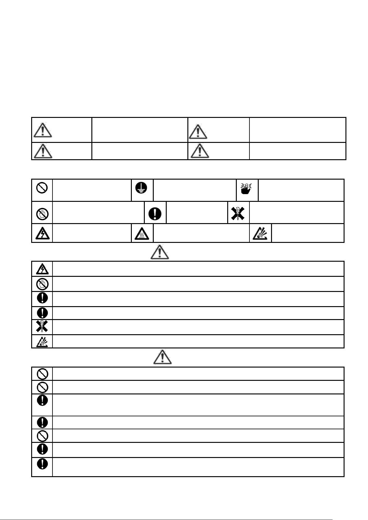
★ Precautions on safety
Alarms are defined and categorized into either one of four groups in this manual, depending on degrees of importance or risk
in terms of the safe use of the equipment or prevention of accident or damage on the equipment. For each alarm, symbol is
assigned as shown below.
★ Alarm symbols
An alarm categorized in the group of Caution may still yield to serious result, depending on circumstances.
Any symbol for the four groups intends to raise user’s attention for important description. Carefully observe it.
Warning
Caution
- 2 -
Page 3
Turn off the power supply before cleaning the equipment, and wipe it with a soft dry cloth. Do not use thinners, as they
may cause deformation or discoloration of the equipment.
The equipment may cause radio disturbances in domestic settings. User is required to take appropriate measure.
Ensure to tighten terminal screws at specified torque. Insufficient tightening the screws may cause an electric shock or
fire.
Ensure to observe precautions listed in this manual for the use of the equipment.
Reprinting or duplicating this manual is prohibited.
This manual may be revised without prior notice.
Abbreviation
Term
PV
Present value
SV
Setting value
AT
Auto-tuning
MV1
Primary operating amount
MV2
Secondary operating amount
CT
Current transformer
0 1 2 3 4 5 6
0 1 2 3 4 5 6
7 8 9
Minus
Period
Slash
7 8 9 - . /
A B C D E F G
A B C D E F G
H I J K L M N
H I J K L M N
O P Q R S T U
O P Q R S T U
V W X Y Z
V W X Y Z
Precaution regarding Export Trade Control Ordinance
Investigation on client or application by an appropriate party is required so that the equipment is not used for mass destruction
weapons and such (military application, military facilities, etc.).
Notation convention in this manual
★ Summary notation
Abbreviations in alphabetical characters are used for the diagrams and text in this manual. Some major examples are as
follows.
- 3 -
Page 4
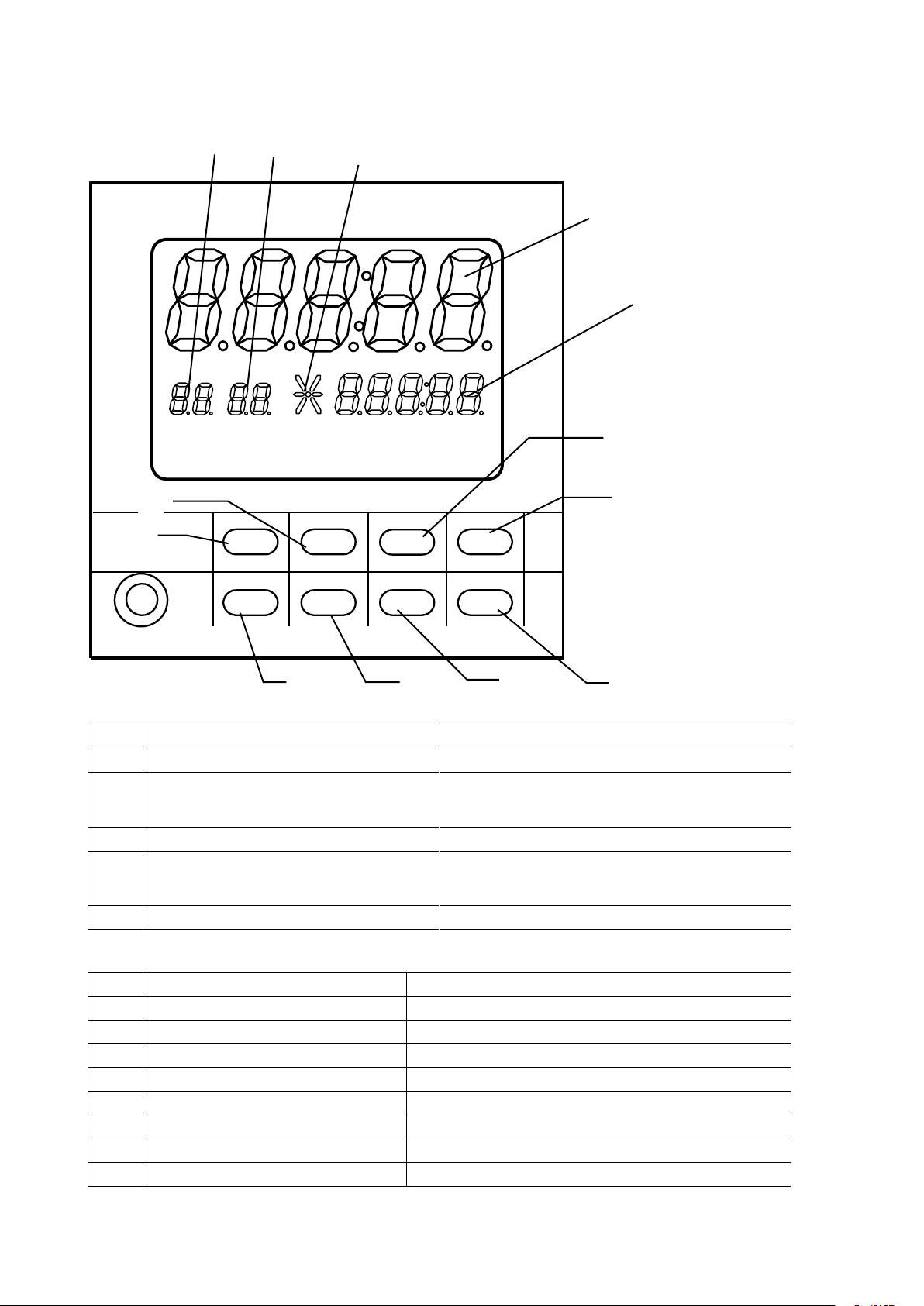
2. Parts indication and Installation
No.
Segment character
Content
①
PV (5 digits in the upper row)
Displays PV, etc.
②
SV (5 digits in the lower row)
Displays SV, etc.
Fixed to 0 during a stop.
Displays “TIME” during a timer run.
③
Pattern digit (2 digits in the lower row left)
Displays the pattern No., etc. presently in selection.
④
Step digit (2 digits in the lower row right)
In a stop: Displays the number of steps of the pattern
presently in selection.
In a run: Displays the step No., etc. presently in progress.
⑤
Operating status (lower row center; 6 segments)
Indicates the program operating status.
No.
Name
Content
A
RUN/STOP key
Used for run start/stop, temporary stop, etc.
B
DSP.CHG key
Used for display switchover, etc.
C
Dig.MOVE key
Shifts the set digit leftward during setting.
D
AUTO/MAN key
Switches over MANU/AUTO.
E
RESET key
Used for screen return, etc.
F
MODE key
Used for changing a setting item, etc.
G
key
Used for decreasing a numerical value, etc.
H
key
Used for increasing a numerical value, etc.
RUN/STOP DSP.CHG D i g..MOVE AUTO/MAN
RESET M O D E
▽ △
RUN
OUT
EV1
EV2
EV3
EV4
TS1
TS2
TS3
TS4
AUTO
MANU
AT
END
TIME
SV
PV
PTN
STP
① ② ③ ④ ⑤
D
G H F
E
C
B
A
2.1 Full panel face
2.2 Segment display section
2.3 Key
- 4 -
Page 5
2.4 Lamp display section
Lamp character
Content
PTN
Lights up while a pattern in display.
STP
Lights up while a step in display.
RUN
Lights up during a program run.
OUT
Lights up at the heating output ON.
EV1
Lights up at occurrence of Event 1.
EV2
Lights up at occurrence of Event 2.
EV3
Lights up at occurrence of Event 3.
EV4
Lights up at occurrence of Event 4.
TS1
Lights up at Time Signal 1 ON.
TS2
Lights up at Time Signal 2 ON.
TS3
Lights up at Time Signal 3 ON.
TS4
Lights up at Time Signal 4 ON.
AUTO
Lights up during an automatic run.
MANU
Lights up during a manual run.
AT
Lights up during an auto-tuning.
END
Lights up at the output ON while End Signal in use.
TIME
Lights up at the time being set.
2.5 Lamp display section
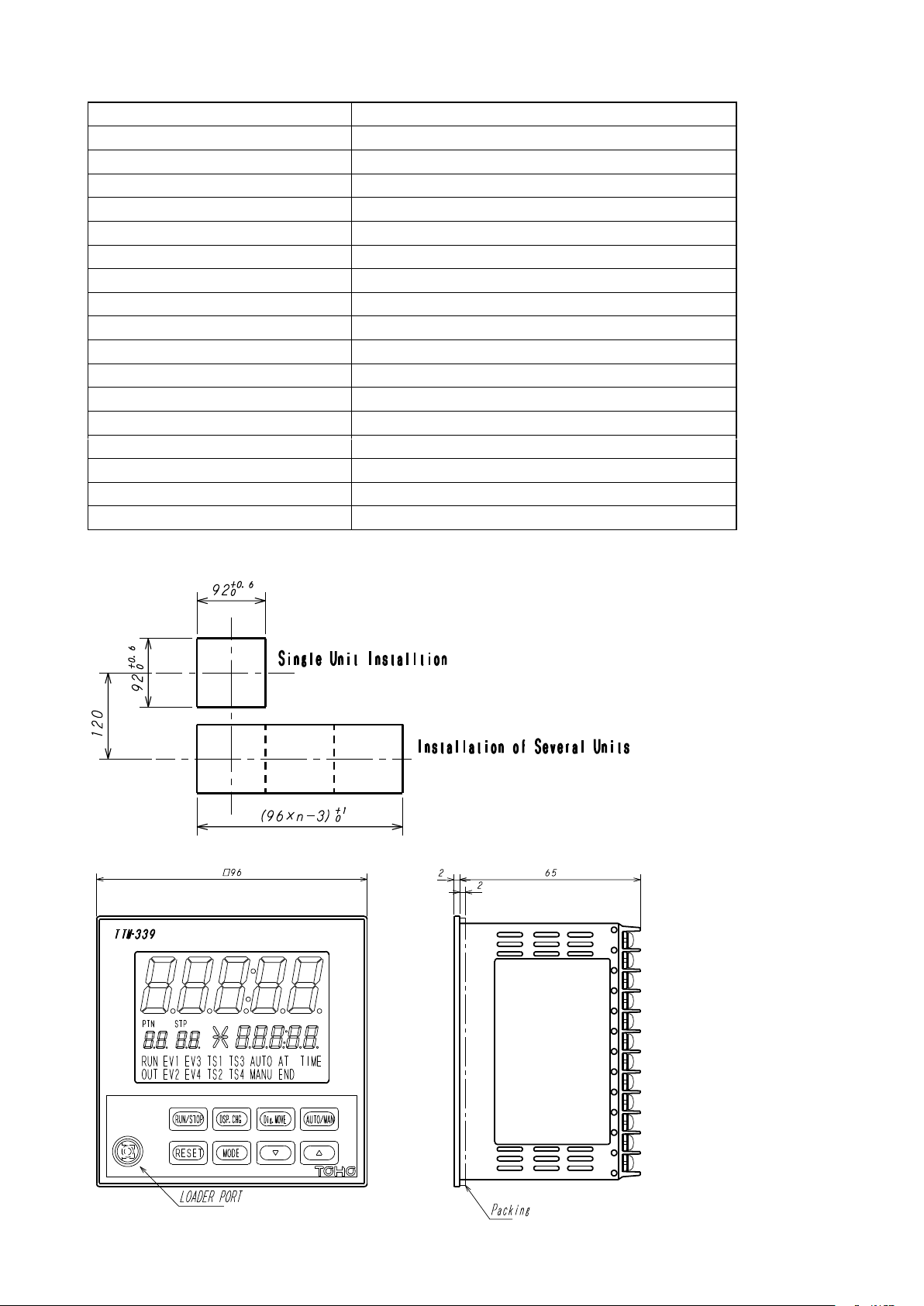
2.6 Outer Dimensions
- 5 -
Page 6
2.7 Precautions on installation
Warning
Ensure to turn the power supply off before beginning removal or reinstallation of the equipment in order to
prevent an electric shock or equipment failure.
★ Ambient temperature and humidity (the equipment to be used in the specified range as listed below)
(1) Temperature range: 0 - 50 °C
(2) Humidity range: 20 - 90% PH (no dew condensation allowed)
(3) Installation gradient: Base plane ± 10 degrees
★ Do not install the equipment in the following places.
(1) Where temperature abruptly changes to generate dew
(2) Where corrosive or flammable gases are generated
(3) Where water, oil, steam or chemicals splatter
(4) Where vibration or noise is directly applied
(5) Where dusty or salty ambience, or many iron scraps is present
(6) Where direct sunlight is received
(7) Where circuits may negatively be affected by static electricity, noise or magnetism
(8) Where direct warm or cool air is received from an air-conditioner
★ Precautions on installation
(1) Provide sufficient space for ventilation so that the ambient temperature does not rise to 50 °C or higher. In case that the
temperature of 50 °C or higher is suspected, use a fan or air-conditioner to cool the ambience.
Take care that no cold air flows directly on the equipment.
(2) Do not install the equipment on a device that may generate large heat, such as heater and transformer.
(3) Install the equipment away as much distant as possible from high-voltage devices, power lines or power equipment.
(4) Do not block off the ventilation opening on the equipment. Ensure a sufficient gap between stacked units of equipment.
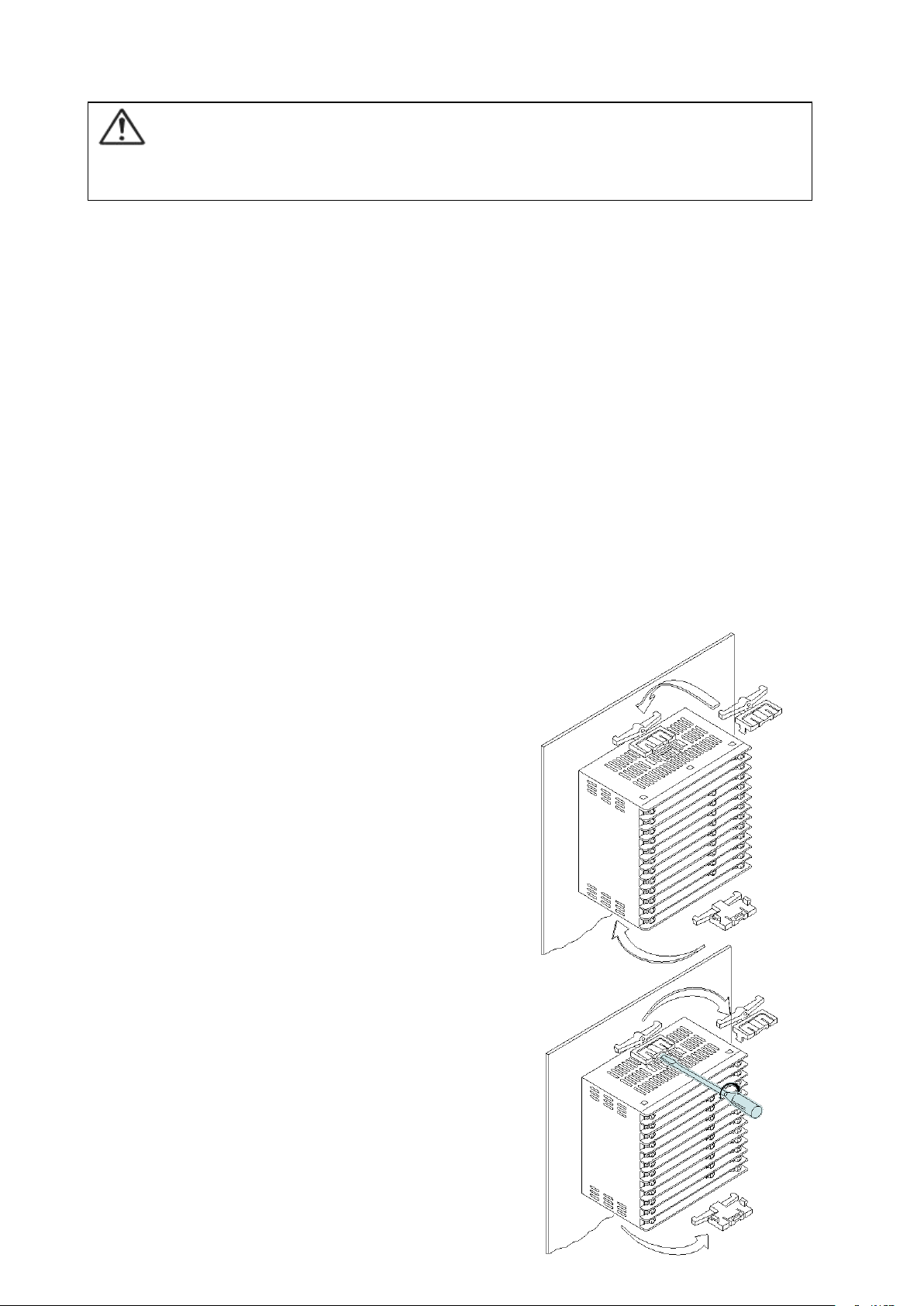
2.8 How to install or remove the equipment
★ Installation on a panel
(1) Make an opening on the panel.
(2) Insert the equipment into the opening.
(3) Install the mounting attachment from behind the panel.
(Ensure that the equipment is securely fixed)
* Conduct wiring after the equipment is installed.
* Turn on the power after the wiring.
★ Removal from the panel
(1) Turn off the power.
(2) Disconnect the wiring.
(3) Insert a flat-head screw driver into the clearance
formed between gabs on the equipment and attachment.
Turn the screw driver clockwise or counterclockwise to
dislocate the gabs to remove the attachment from
the equipment.
(4) Remove the equipment from the panel.
* Ensure to conduct removal work after
turning off the power.
- 6 -
Page 7
3. Terminal connection diagram
Power supply
100 to 240 VAC
① X
A
Communications RS-485
⑬
EV4
Open collector
output
② B ⑭
TS1
Not in use
③
Pattern 1
No-voltage
contact input
⑮
TS2
OUT1
(Relay/SSR/4 -20
mADC)
C
④
Pattern 2
⑯
TS3
NO
⑤
Pattern 3
⑰
TS4
OUT2(None/Relay/
SSR/
4 -20 mADC)
C
⑥
Pattern 4
⑱
TIME
NO
⑦
RUN/RDY
⑲
COM
Not in use
⑧
Operation
switchover
⑳
CT input
Relay contact
output
EV1
⑨
Step feed
EV2
⑩
COM
Sensor input
* See below.
EV3
⑪
END signal
Relay contact
output
COM
⑫ Y
COM
RTD
TC/10 mV
Current/voltage
b
B
A
Warning
Do not turn on the power until all wiring is complete in order to prevent an electric shock
or equipment failure.
Precautions on wiring
★ For inputs from a thermocouple, use the specified wires or compensating leads.
★ For inputs from a resistance temperature detector, use wires that the wire resistance of leads is small and no resistance difference
★ Provide input signal lines distant from power supply lines, power lines or load lines so as not to affect input signal lines with
★ Wire the power supply for instruments such that they do not receive noises from the power supply for power devices.
★ For the power supply, use and twist wires that cause less voltage drop.
★ For the equipment being activated, it takes about 4 seconds after its power turns on. Use delay relays when using the
★ The equipment is not attached with power supply switch fuses. Separately install fuses in proximity of the equipment, as
★ Use crimping terminals that match screw sizes.
is present among 3 wires (3-wire type).
noise induction.
The use of a noise filter is recommended in case that the equipment is vulnerable to noises.
Take care the following when a noise filter is used.
◎ Install the noise filter as close to a temperature controller as possible.
Wire the instruments in as short a distance as possible to output lines (secondary side) of the noise filter and power
terminals for the temperature controller.
◎ Isolate the noise filter input line (primary side) from its output line (secondary side).
High-frequency elements of noises may be induced, resulting in no provision of much noise attenuation effect as expected,
in case of input and output wires being close one another, such as being bundled together or installed in a same duct or
tube.
◎ Wire the grounding wire of the noise filter in as short a distance as possible.
A long grounding wire is equivalent to insert of an inductance, resulting in deteriorated high-frequency characteristics.
◎ Before installing the noise filter, peel off the paint applied on a mounting plate of the noise filter as appropriate, in order to
reduce the contact resistance between the noise filter and equipment housing.
equipment for generating signals for interlocking circuits.
needed.
◎ Recommended fuse rating: Rated voltage of 250 V and rated current of 1 A
◎ Size of crimping terminal: Terminal width of 6 mm or smaller
Crimping terminal recommended
Manufacturer: NICHIFU
Model: ICTV-1.25Y-3N (Y terminal)
ICTV-1.25-3S (round terminal)
◎ Tightening torque recommended: 0.5 Nm
◎ Applicable wire
Use wires in sizes suitable for the terminals.
- 7 -
Page 8
The use of shielded wires is recommended.
Pattern No.
1 2 3 4 5 6 7
8
Step No.
99
49
33
24
19
16
14
12
Pattern No.
9
10
11
12
13
14
15
Step No.
11 9 9 8 7 7 6
RUN
OUT
EV1
EV2
EV3
EV4
TS1
TS2
TS3
TS4
AUTO
MANU
AT
END
TIME
PTN
STP
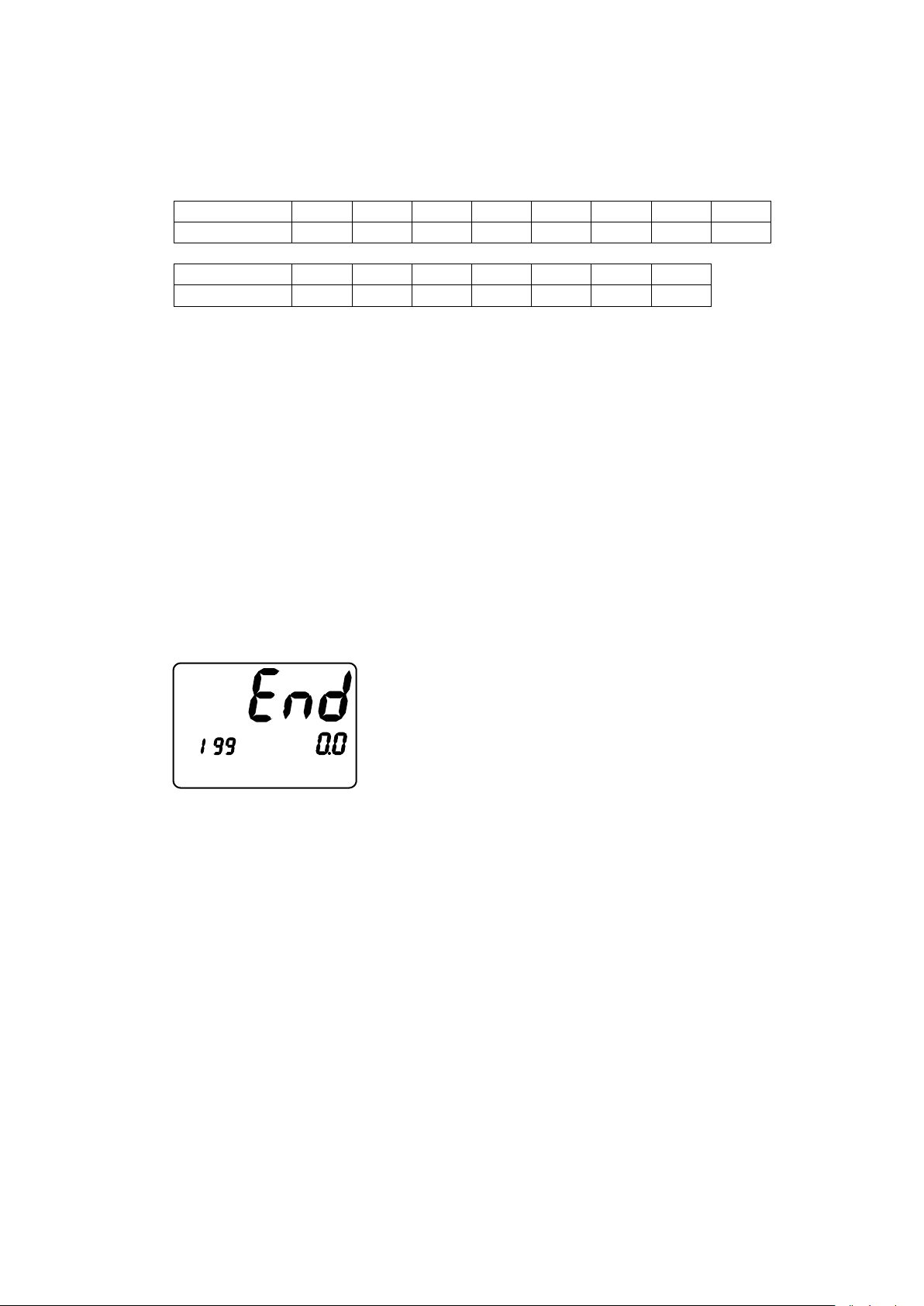
• The screen shown in the left is the normal one.
For Pt100 (resistance temperature detector), use identical wires of low lead resistance and no resistance difference among
3 wires.
4. Terms and Various Functions
4.1 Program run
* The following number of steps is fixedly set, depending on the number of patterns.
To make control, SV is changed parallel to the temperature and time set for each pattern.
If a setting is made to the lower limit within [a setting range - 1] (“----” to be displayed) in the temperature setting for
each step, steps following the said step is ineffective and no setting parameter is displayed.
The pattern run ends at one step prior to the step set as “----.”
Neither the step temperature nor the step time in a run can be changed.
If the setting temperature of the step 1 is set at SLL for a PV start, the time of step 1 is effective and a timer run begins.
(The normal PV start begins with the step 2.)
“TIME” is displayed in the SV display frame.
If the setting temperature for all steps is 0, setting a temperature for a step results in the next step automatically being set
to the same temperature (only at key operation).
If the step time is set above the upper limit within the setting range (“~~~~~” to be displayed), the step continuously runs
at the setting temperature.
Each pattern repeats for the number of times that has been executed. When the setting is set to “0”, it will continue to
repeat until it is stopped with key operation. (max. 9999 times)
During a run, the TIME output is ON.
For display during the program run, see Section 5.3.2 “Auto run (normal mode).”
The following is displayed upon termination of the program.
4.2 Step feed/step return
Holding the “” key pressed for 3 seconds during a run results in the step feed to transfer to the next step.
Holding the “” key pressed for 3 seconds results in the step return to transfer to the step one previous to the current
step.
In the case of the external drive signal selection being ON, the step feed is executed when open of the step feed DI
changes to closed.
Only the timer is reset when the step return is executed at step 1 (or the leading step).
If the step feed is executed at the step for the endless setting, END is established.
*When the External Drive Signal Selection is set to ON, Step Forward/Reverse with key operation will not be
effective.
4.3 Elapsed time increase/decrease
During a program run, pressing the / key on the elapsed time screen results in an increase/decrease of the elapsed
time.
The unit of the elapsed time is minute. Counting the number of seconds continues.
The change range of the elapsed time is 0 to [the setting time in a run - 1].
The change range of the elapsed time for a wait zone is 0 to [the setting time in a run + the wait time - 1].
Execution of an increase/decrease in the wait zone results in an increase/decrease of the elapsed time; however, setting
the elapsed time below the setting time results in a return to the normal step run but not to the wait zone.
This function is ineffective for an end signal.
- 8 -
Page 9
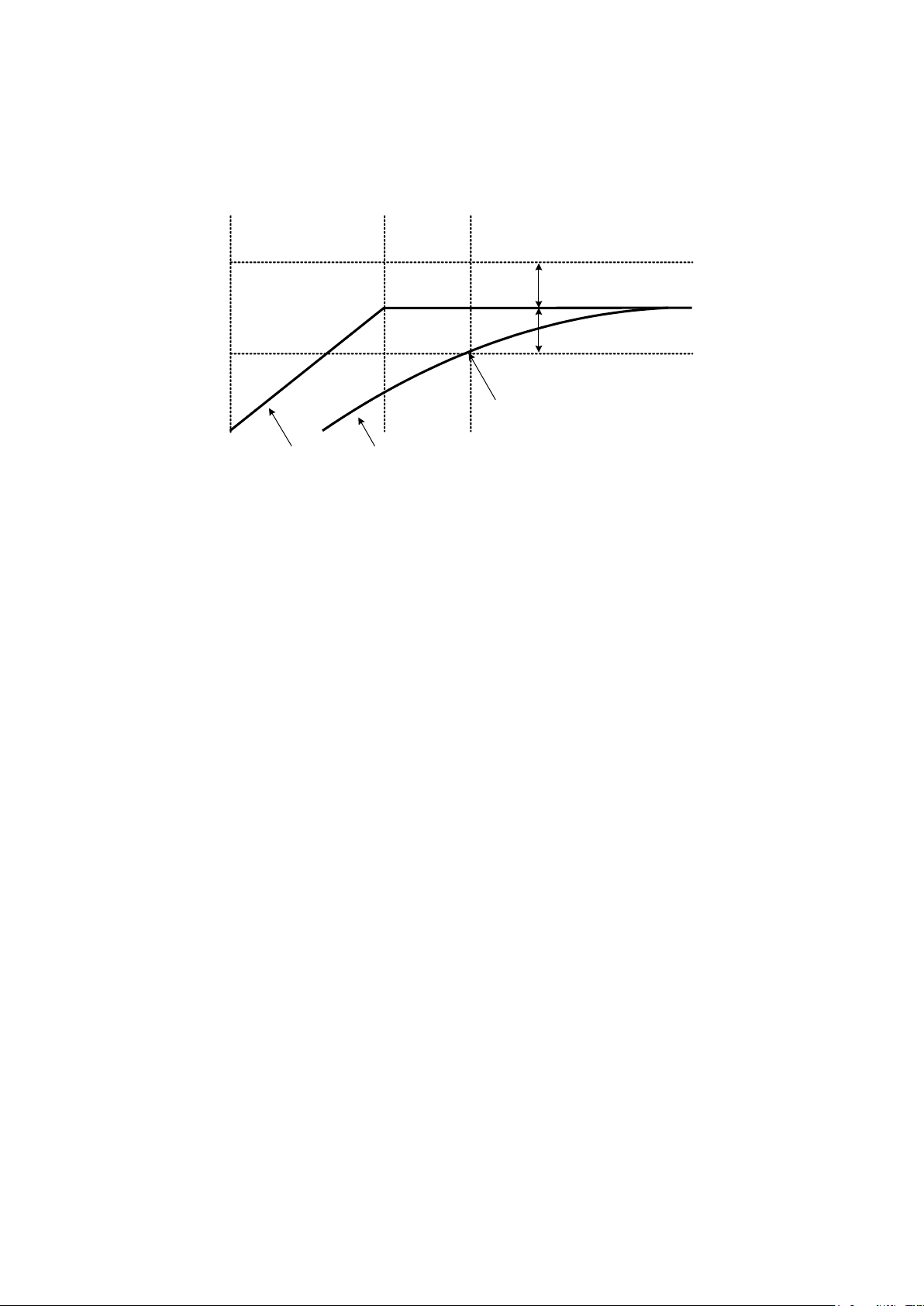
4.4 Wait function
Wait zone
Wait zone
Present step Next step
SV PV
In a wait
As PV enters into the wait zone, a transfer to
the next step is made.
Even if PV does not enter into the wait
zone, a transfer to the next step is
made when the wait time elapses.
For the current step transferring to the next step, the next step does not begin if PV has not reached the wait zone
(similarly, if PV has overreached) after the step time elapsed.
However, if the wait time elapses, the next step begins at that point.
The above operation is executed by selecting 0 to 4 for each step, or by setting value for 1 to 4.
Selecting 0 indicates no function.
In the case of [the wait zone setting = 0], in-a- wait is effective until PV goes beyond SV.
4.5 Three-zone PID function
Numerical values of P, I, D and PC are switched over at each of the low, intermediate and high temperatures.
The ranges of the three zones are as follows:
- Low temperature (PID No. 1): SLL to intermediate point 1
- Intermediate temperature (PID No. 2): Intermediate point 1 to intermediate point 2
- High temperature (PID No. 3): Intermediate point 2 to SLH
4.6 Auto tuning function
Auto tuning starts at each of low, intermediate and high temperatures.
Auto tuning starts when the temperature at which the auto tuning is to be performed is set on each startup screen and the
RUN/STOP key is pressed or by an Auto tuning start command of the communication.
During the auto tuning, AT-1 (to 3) and SV are alternately displayed in the SV display digit ,and ATALL and PV are
alternately displayed in the PV display digit.
Re-pressing the RUN/STOP key results in a stop of the auto tuning.
If the auto tuning has not terminated 3 hours after its start, an AT error is established and the run stops, displaying
“ERR2.”
Attempting an auto tuning during an automatic run results in first a temporary stop and then start of the auto tuning.
During a manual run, the auto tuning is not possible.
4.7 PV start/SV start
At a start of the program run after selecting the PV start and SV start, the start SV indicates the following:
PV start:
The run starts from the ramp step of upward slope in which the measurement temperature is included.
In addition, the run starts from the elapsed time, of which amount is assumed to elapse to come to the start point.
The calculation is made with the start point of 0C /0 digit.
For below 0C /0 digit, the calculation is made with the elapsed time of 0 minute.
SV start: The program run starts from the SV start temperature setting.
- 9 -
Page 10
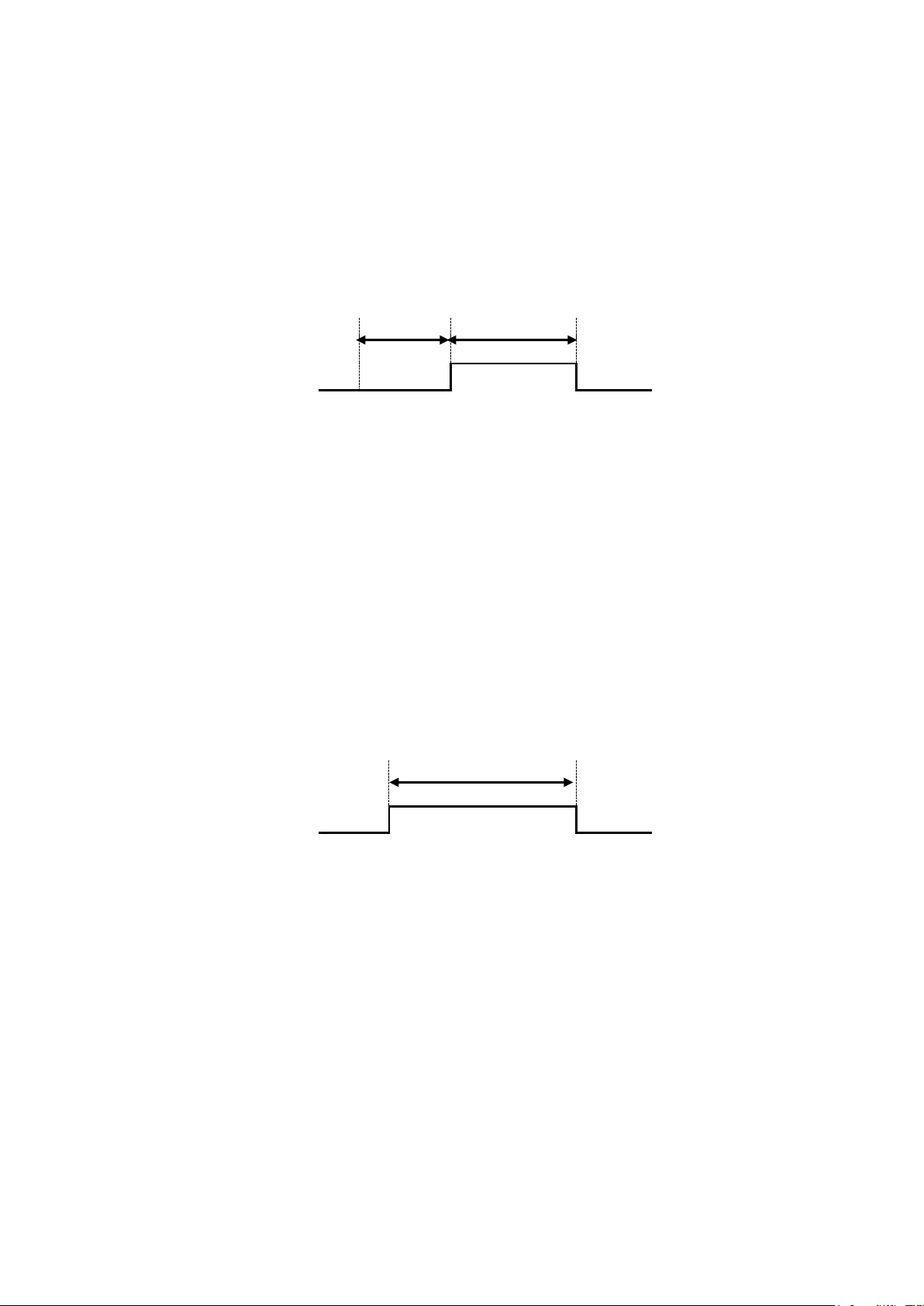
4.8 Time signal output
ON time
OFF time
Output
ON time
Output
At starting each step, the time signals 1 to 4 are turned on upon elapse of the time set on the ON delay timer.
Then, the output is turned off upon elapse of the time set on the OFF delay timer.
During the time signal output ON, corresponding lamps of TS1 to TS4 light up.
Select the function selection among 0 to 5 of TS 1 to 4 at each step; if either one of 1 to 4 is selected, the above
operation is performed with the setting; if 0 is selected, no function is available; if 5 is selected, ON is always set
during the selection step.
If the time is set backward by using the or key, even after elapse of time, the output returns to the one
corresponding to the point at which the time set backward and time counting starts at that point, i.e., in the middle
of the way.
Example: If the elapsed time is returned by 5 minutes by using the key 3 minutes after the OFF delay
terminates, the output turns on and the OFF delay counts for 2 minutes.
△
Step start
4.9 Time output
During a program run, the Time output is always ON as in-a-run signal output.
4.10 In-a-run signal output/end signal output selection function
The use purpose of one relay output is selected from either in-a-run signal output or end signal output.
4.10.1 When selecting the in-a-run signal output
During a run, the relay output is always ON as in-a-run signal output.
4.10.2 When selecting the end signal output
At termination of the program run, the output as the end signal output is turned on or off according to the
following flow.
If the setting is above the maximum value within the setting range (“~~~~~” to be displayed), the output remains
turned on until the reset status described in Section 5.3.1 is established.
Also, the END lamp lights up.
△
Termination of the program run
4.11 DI (external input)
Operation including run can be performed via DI through the external drive signal selection.
For the function of each DI, see Sections 4.10.1 to 4.10.4.
No operation is performed for [external drive signal = OFF].
4.11.1 Run/reset DI
The following operation is performed when ON continues for 2 seconds after the external contact open (OFF)
changes to the external contact closed (ON):
During a run: The run stops.
During a stop: A run starts.
4.11.2 Hold DI
The following operation is performed when ON continues for 2 seconds after the external contact open (OFF)
changes to the external contact closed (ON):
During a run: The run stops momentarily.
During a momentary stop: The run restarts.
4.11.3 Step feed DI
- 10 -
Page 11

The step changes when the external contact open (OFF) changes to the external contact closed (ON) during a
program run.
4.11.4 Patterns 1 to 4 DI
A pattern is selected from 1 to 15, which are configured by combination of the external contacts 1 to 4 closed (ON)
and open (OFF).
No switchover of a pattern No. is possible during a run.
If all external contacts 1 to 4 are open (OFF), choose the pattern No. selected in the pattern No. setting mode.
Pattern 1 DI: 1
Pattern 2 DI: 2
Pattern 3 DI: 4
Pattern 4 DI: 8
Example: If both pattern 1DI and pattern 3DI are ON, selected pattern No. is: 1 + 4 = 5.
4.12 Auto run (AUTO)/manual run (MANU)
The base of a run is the auto run (AUTO); the auto run, however, changes to the manual run (MANU) by
holding the AUTO/MANU key pressed for 3 seconds.
No control is performed during a manual run, but the operation amount is output in a display.
The displayed operation amount is identical to the SV displayed in the lower row on the PV/SV screen in the
normal mode.
Pressing the / key in this status results in a change of the operation amount to be output.
The operation amount and step time are as follows at the start of a manual run:
Operation amount
In the case of in-a-stop: Starts with the operation amount of 0.0%.
In the case of in-a-run: Starts with the operation amount at the time of switchover
Step time
In the case of in-a-stop: Remains in a stop (no step time counting begins).
In the case of in-a-run: The step time elapses (remains in a stop during a momentary stop).
Re-holding the AUTO/MANU key pressed for 3 seconds results in a return to the auto run.
The AUTO and MANU lamps lights up as follows:
During an auto run: The AUTO lamp turns on and the MANU lamp turns off.
During a manual run: The AUTO lamp turns off and the MANU lamp turns on.
The output interval during a manual run is fixed to 10 seconds.
4.13 Operation amount limiter
By using the operation amount function selection, “no limit function” can be set or two types of operation
amount limiters can be effective.
In addition, two types of limiters can be effective by using the other operation amounts limiter setting described
in Section 4.13.3.
4.13.1 Operation amount limiter
The operation amount is limited by using the primary/secondary control operation amount upper limiters and
Primary/secondary control operation amount lower limiters selected by the operation amount limiter function
selection at each step.
If the operation amount limiter function selection is 0, then 0.0 to 100.0 % is applicable.
- 11 -
Page 12

4.13.2 Operation amount current limiter
100%
Operation amount
0
Temperature
0℃
=SLL
1200℃
=SLH
120℃ 240℃ 360℃ 480℃ 600℃ 720℃ 840℃ 960℃ 1080℃
30A
Current
0
- For an input below the table range, the SLL operation amount and the current value are used for calculation.
- For an input above the table range, the SLH operation amount and the current value are
used for calculation.
Temperature
0℃
=SLL
1200℃
=SLH
120℃ 240℃ 360℃ 480℃ 600℃ 720℃ 840℃ 960℃ 1080℃
AHC
* The limiter on the current side is at the location indicated by
([setting value - sensitivity]) at each point.
The operation amount and current value are limited at each point obtained by dividing SLL to SLH into 10.
At the operation amount limiter points 1 to 11, the operation amount resulted from calculation is limited.
At the current value limiter points 1 to 11, the operation amount is limited by the operation amount at the
current value limiter point determined from a measured current value and present operation amount if the
measured current value at each point exceeds the value [setting value - current limiter sensitivity].
This operation amount changes each time when measuring the current value.
The final operation amount is limited by using either smaller limit of the above two.
The function is effective when [OUT 2 selection = 4 to 20mA], CT existent, [CNT = 1] and operation amount
current limiter effective. OUT2 outputs MV1 (equivalent to OUT1).
- 12 -
Page 13

Example:
15A
Current
0% 60.0%
15A
Current
0% 60.0%36.0%
(10A-1A =)9A
0A0A
Operation
amount
Operation
amount
Calculated operation
amount
Limited operation
amount
100%
100%
0%
0%
Time
Assume the following for various settings and PV:
PV = 120 C, operation amount limiter point 2 = 75.0%, current value limiter point 2 = 10.0 A, present operation
amount = 60.0% and AHC = 1.0 A.
If measured current valued = 15 A:
Based on the relation [0 to present operation amount (60.0%) = 0.0 to measured current value (15.0 A)], the
operation amount [current value limiter point 2 (10.0 A) - current limiter sensitivity (1.0 A)] is to be determined.
The calculation results in the operation amount of 36.0%.
* The operation limiter point 2 = 75.0%; as this amount is larger than the operation amount resulted from the
calculation, the operation amount is eventually limited at 36.0%.
4.14.3 Other operation amounts limiter setting
4.14.3-1 Primary/secondary control operation amount change limiter increase setting
Setting items:
Primary/secondary control operation amount change limiter increase setting: 0.0 to 549.9 [%] (no function by
setting at 0.0 [%])
Operation description:
The increase rate of variation of a calculated operation amount is limited.
The operation amount allowed to increase for a second is set in percent.
The setting is effective during AT.
If the setting is changed, control results also changes; redo AT.
If the setting is 100%, the variation increases only up to 20 % for input sampling (200 ms).
To increase up to 100% for input sampling (200 ms), set at 500%.
(1 second 200 ms) 100% = 500%
- 13 -
Page 14

4.14.3-2 Primary/secondary control operation amount increase time
100%
Operation amount
Time
0
oHtM
Calculated operation amount
Limited operation amount
0%
oHtM
RDY
RUN
* No compensation applies
after the setting time.
Calculated operation
amount
Limited operation
amount
100%
100%
0%
0%
Time
RUN
OUT
EV1
EV2
EV3
EV4
TS1
TS2
TS3
TS4
AUTO
MANU
AT
END
TIME
PTN
STP
Setting items:
Primary/secondary control operation amount increase time: 0 to 3600 [second] (no function by setting at 0
[second])
Operation description:
For a remote run, apply a limit on the operation amount such that the ratio of the operation amount to the
calculated operation amount is from 0% at the start to 100% at the setting time.
The setting is effective also during AT.
If the setting is changed, control results change; redo the AT.
Operation is performed only at the control start (RDY to RUN or MAN or AT)
Care must be used, as no limit applies by the operation amount increase time after the setting time.
4.15 Key lock
When a change of each parameter is attempted in a lock after lock ON/OFF is elected, “LOC” is displayed in the
SV display section.
- 14 -
Page 15

4.16 PV filter setting
Input signal
0%
100%
100%
0%
100%
0%
Damping time constant (PdF1)
63%
Read-in input
(No filter)
Read-in input
(With a filter)
100%
0%
100%
0%
Damping time constant (PdF1 + PdFS)
63%
63%
Damping time constant (PdF1)
Normal PV filter
(PV filter setting only)
Special PV filter
Time added for PdFS
Input signal
0%
100%
4.16.1 PV filter setting
This setting is a function to achieve the CR filter effect on the software by performing a primary delay
calculation on the PV of the input 1.
The filter effect is set with the damping time constant [t].
(Damping time constant is defined as time when PV reaches about 63% in a stepwise change of input.)
* CR filter: Filter of first order lag
Application of a PV filter:
(1) By elimination of high-frequency noise, effect of noise is mitigated when electric noise applies to input.
(2) Response can be delayed for an abrupt change of input.
4.16.2 B thermocouple/PR40-20 special PV filter setting
This setting is a function for the input 1 to add the PV filter setting time further with a limitation of a particular
range on the B thermocouple and PR40-20.
Filter effect is set by the damping time constant [t].
The effective range of the set filter is as follows:
(1) B thermocouple: In the case of 400C or below
(2) PR40-20: In the case of below 800C
- 15 -
Page 16

4.17 Event alarm
RUN
OUT
EV1
EV2
EV3
EV4
TS1
TS2
TS3
TS4
AUTO
MANU
AT
END
TIME
PTN
STP
RUN
OUT
EV1
EV2
EV3
EV4
TS1
TS2
TS3
TS4
AUTO
MANU
AT
END
TIME
PTN
STP
RUN
OUT
EV1
EV2
EV3
EV4
TS1
TS2
TS3
TS4
AUTO
MANU
AT
END
TIME
PTN
STP
Press the MODE key.
Hold the MODE key pressed as is although a
change is made to the common parameter
setting 3 seconds after pressing the MODE key.
Holding the MODE key pressed for 10
seconds on the PV/SV screen results in
blinking display. Pressing the MODE key
and then the RESET key results in a change
to the blind mode.
MODE key
Input 1 type
MODE key
△・▽ key
△・▽ key △・▽ key
△・▽キー
To PID
To PV-SV
To SET 3
to SET 11
To the following
items
Three-second prolonged
press of the MODE key
MODE key
function setting
MODE key
To the following
items
Setting temperature
MODE key
By setting the events 1 to 4 function setting, outputs of EV 1 to 4 are turned on if PV is located within the alarm range.
Corresponding EV1 to EV4 lamps light up.
By switching over the events 1 to 4 polarities, selection of open/closed is possible at the turn-on.
Output is also turned on at occurrence of a loop abnormality when the events 1 to 4 function 2 setting is effective.
* For loop abnormality, see Section 8.17 “ Loop abnormality.”
The setting can be released by using the key or reset DI, provided that the following condition is met:
(1) Normal status at the release
(2) Standby existent even if abnormality status at the release
Judgment process is performed only during a run (no judgment made during a stop).
Restoration from a power outage is made for the status previous to the outage.
4.18 Loop abnormality
When the primary/secondary control loop abnormality PV change amount setting is not 0, the PV change amount is
determined every loop abnormality time setting time if the present step is a soak.
Consequently, “loop abnormality” occurs if the following condition is met: ⊿PV Primary/secondary control loop
abnormality PV change amount setting.
Function OFF is established if the primary/secondary control loop abnormality PV change amount setting is 0.
4.19 Blind Function
Holding the MODE key pressed for 10 seconds on the PV/SV screen results in the blind mode.
In the blind mode, “ON” and “OFF” are displayed in the lower row for each character (SV display section). “ON”
indicates display and “OFF” indicates no display (blind). Note that a batch setting applies for the PV/SV screen,
elapsed time screen and operation amount screen.
For a character change in the blind mode, use the DSP.CHG key.
To terminate the blind setting mode, either turn off the power or hold the MODE key pressed for 10 seconds on the
PV/SV screen.
For blind items, see “L/B” in the column of “Command” in Operation Specifications “List of communications
items.”
- 16 -
Page 17

4.20 Electric Power Outage Function
1) 2) 3)
During
END
4)
During a
timer run
PV
Time
Upon recovery of the electric power after its outage during a run, the status at the time of the outage is restored
under the following conditions. Note that, if the PV at restoration is out of the range of [PV electric power
outage restoration temperature width], the restoration is made as a stop.
Alarm statuses of the event function are also restored.
1) If the step 1 is in the status of a timer run (SV=SLL):
Restored at the location at the time of the outage.
2) In the case of in-a-ramp of SV increase or in-a-soak:
Restored with the PV start.
Restored with the run end “END” if no SV present.
3) In the case of in-a-ramp of a SV decrease or in-a-soak after the decrease:
Restored with the PV start at the step of the decrease if PV decrease point.
Restored with the run end “END” if PV decrease point.
4) In the case of in-“END”:
Restored to “END.”
5) Restored with a temporary stop for the items 1 through 3 if a power outage occurs during a temporary stop.
6) In the case of in-a-manual-run:
Restored with a stop status.
- 17 -
Page 18

5. Flow of Mode Change Operation and Run Operation
5.1
Primary Power Source in
the OFF status
5.2
Initial mode
Primary power
source ON
5.3
Normal mode
5.4
Pattern No. setting mode
5.5
Program setting mode
4 seconds
elapsed
In a stop: Display switchover key only
In a run: Display switchover key: 3
seconds
5.6
Common parameter setting
mode
5.7
Alarm temperature setting
mode
5.8
PID setting mode
Reset
MODE key
Reset
MODE key: 3 seconds
Reset
MODE key +▽ key: 3 seconds
Reset
MODE key + △ key: 3 seconds
Reset
5.3.1
Reset
5.3.2
Auto run
5.3.3
Temporary stop
< Normal mode >
RUN/STOP key: 2 seconds
RESET key: 2 seconds
RUN/STOP key
5.3.4
Manual run
AUTO/MAN key: 3 seconds
AUTO/MAN key: 3 seconds
It takes about 2 seconds from the primary
power source ON until the initial mode.
Primary power
source OFF
- 18 -
Page 19

Flow of the program setting mode
Pattern No. setting mode
MODE key
Step 1 temperature
setting
Step 1 time setting
Step 2 temperature setting
Step 2 time setting
MODE key
Step □ temperature setting
Step □ time setting
Similarly make settings up to the
maximum step.
(Varies, depending on the number of
patterns.)
□
□
MODE key
END signal ON time setting
DSP.CHG key +
MODE key
MODE key MODE key
Step 1 wait function
existence/nonexistence
setting
Step 1 time signal 4
function existence/
nonexistence setting
MODE key MODE key
MODE key
MODE key
MODE key MODE key
□ □
MODE key
Step 1 operation
amount limiter function
setting
MODE key
MODE key
□
MODE key + △ key
MODE key + △ key
MODE key + △ key
MODE key + △ key
MODE key
Step 1 time signal 1
function existence/
nonexistence setting
MODE key
MODE key
□
* There are time signals 1 to 4.
MODE key
MODE key + △ key
DSP.CHG key +
MODE key
DSP.CHG key +
MODE key
Step 2 wait function
existence/nonexistence
setting
Step 2 time signal 4
function existence/
nonexistence setting
Step 2 operation
amount limiter function
setting
Step 2 time signal 1
function existence/
nonexistence setting
Step □ wait function
existence/nonexistence
setting
Step □ time signal 4
function existence/
nonexistence setting
Step □ operation
amount limiter function
setting
Step □ time signal 1
function existence/
nonexistence setting
- 19 -
Page 20

Flow of the Common parameter setting mode
Normal mode
△ key
MODE key
MODE key
MODE key
MODE key: 3 seconds
MODE key
MODE key
MODE key
MODE key
MODE key
MODE key
MODE key
MODE key
▽ key
△ key▽ key
△ key▽ key
△ key▽ key
△ key▽ key
△ key▽ key
△ key▽ key
△ key▽ key
△ key▽ key
△ key▽ key
△ key▽ key
△ key▽ key
MODE key
MODE key
△ key▽ key
To settings of
SET1
To settings of
SET2
To settings of
SET3
To settings of
SET4
To settings of
SET5
To settings of
SET6
To settings of
SET7
To settings of
SET8
To settings of
SET9
To settings of
SET10
To settings of
SET11
To settings of
SET12
To settings of
SET13
Normal mode
MODE key
MODE key
MODE key
MODE key
MODE key
MODE key
MODE key
MODE key
Event 1 upper limit setting
Event 1 lower limit setting
MODE key + ▽ key: 3 seconds
Event 2 upper limit setting
Event 2 lower limit setting
Event 3 upper limit setting
Event 3 lower limit setting
Event 4 upper limit setting
Event 4 lower limit setting
Normal mode
MODE key
MODE key
MODE key
MODE key
Proportional band setting of PID No. 1 (low temperature)
Integral time setting of PID No. 1 (low temperature)
MODE key + △ key: 3 seconds
Derivative time setting of PID No. 1 (low temperature)
Intermediate point 1 setting for the PID range
MODE key
MODE key
MODE key
Proportional band setting of PID No. 2 (intermediate temperature)
Integral time setting of PID No. 2 (intermediate temperature)
Derivative time setting of PID No. 2 (intermediate temperature)
Intermediate point 2 setting for the PID range
MODE key
MODE key
MODE key
MODE key
Proportional band setting of PID No. 3 (high temperature)
Integral time setting of PID No. 3 (high temperature)
Derivative time setting of PID No. 1 (high temperature)
Flow of the Alarm temperature Flow of the PID setting mode
setting mode
- 20 -
Page 21

5.1 List of settings in the pattern No. setting and program setting modes
Name
Setting content
Initial value
1
SV *
Setting temperature (*1)
- (Termination of a run); SLL to SLH
0
2
W *
Wait function setting (*1)
0 to 4 (0 stands for no function)
0
3
TS1 *
Time signal 1 function setting (*1)
0 to 5 (0 stands for no function and 5 for in-a-selection step ON)
0
4
TS2 *
Time signal 2 function setting (*1)
0 to 5 (0 stands for no function and 5 for in-a-selection step ON)
0
5
TS3 *
Time signal 3 function setting (*1)
0 to 5 (0 stands for no function and 5 for in-a-selection step ON)
0
6
TS4 *
Time signal 4 function setting (*1)
0 to 5 (0 stands for no function and 5 for in-a-selection step ON)
0
7
ML *
Operation amount limiter function setting (*1)
0 to 4 (0 stands for no function)
0
8
T *
Setting time (*1)
0:00 to 99:59 (hour: minute); ~ (endless setting)
00:00
9
RNC
running times
0 - 99 times (0 for infinite number)
1
10
E ON
End signal ON time
0:00 to 99:59 (hour: minute); ~ (ON hold)
00:00
SET01
Name
Setting content
Initial value
1
PAT
Number-of -patterns setting (*2) (*3)
1 to 15 (pattern)
1
2
PVSV
PV start/SV start selection (*2)
PV
PV start
PV
SV
SV start
3
SVSV
Start temperature setting at SV start (*2)
Thermocouple/RTD input SLL to SLH (C)
0
Current/voltage input SLL to SLH (digit)
4
RNES
In-a-run output/end signal output selection
(*2)
0
In-a-run output
0
1
End signal output
5
ERUN
External drive signal selection (*2)
OFF
Internal run
OFF
ON
External run
6
TPV
Power outage restoration temperature width
setting
Thermocouple/RTD input 0.0 to 2999.9 (C) or 0 to 2999 (C)
0
Current/voltage input 0 to 29999 (digit)
SET02
Name
Setting content
Initial value
* Below, 1 and 2 are for the wait function setting, i.e., effective when 1 is selected.
1
WZ1
Wait zone 1 setting
Thermocouple/RTD input 0.0 to 999.9 (C) or 0 to 999 (C)
0
Current/voltage input 0 to 9999 (digit)
2
WT1
Wait time 1 setting
0:00 to 99:59 (hour: minute)
00:00
* Below, 3 and 4 are for the wait function setting, i.e., effective when 2 is selected.
3
WZ2
Wait zone 2 setting
same as Wait zone 1
0
4
WT2
Wait time 2 setting
00:00
* Below, 5 and 6 are for the wait function setting, i.e., effective when 3 is selected.
5
WZ3
Wait zone 3 setting
same as Wait zone 1
0
6
WZ3
Wait time 3 setting
00:00
* Below, 7 and 8 are for the wait function setting, i.e., effective when 4 is selected.
7
WZ4
Wait zone 4 setting
same as Wait zone 1
0
8
WT4
Wait time 4 setting
00:00
SET03
Name
Setting content
Initial value
* Below, 1 and 2 are for the time signal function setting, i.e., effective when 1 is selected.
1
ONT1
Time signal ON delay timer 1
0:00 to 99:59 (hours:minutes)
00:00
2
OFT1
Time signal OFF delay timer 1
0:00 to 99:59 (hours:minutes)
00:00
* Below, 3 and 4 are for the time signal function setting, i.e., effective when 2 is selected.
3
ONT2
Time signal ON delay timer 2
0:00 to 99:59 (hours:minutes)
00:00
4
OFT2
Time signal OFF delay timer 2
0:00 to 99:59 (hours:minutes)
00:00
* Below, 5 and 6 are for the time signal function setting, i.e., effective when 3 is selected.
5
ONT3
Time signal ON delay timer 3
0:00 to 99:59 (hours:minutes)
00:00
6
OFT3
Time signal OFF delay timer 3
0:00 to 99:59 (hours:minutes)
00:00
* Below, 7 and 8 are for the time signal function setting, i.e., effective when 4 is selected.
7
ONT4
Time signal ON delay timer 4
0:00 to 99:59 (hours:minutes)
00:00
8
OFT4
Time signal OFF delay timer 4
0:00 to 99:59 (hours:minutes)
00:00
5.2 Common parameter setting mode SET 1
5.3 Common parameter setting mode SET 2
5.4 Common parameter setting mode SET 3
- 21 -
Page 22

SET04
Name
Setting content
Initial value
1
SLH
SV limiter upper limit (*2) (*3)
Thermocouple/RTD input (SLL + 5.0) to SV setting range upper limit (C)
(SLL + 5) to SV setting range upper limit (C)
1200
Current/voltage input (SLL + 50) to SV setting range upper limit (digit)
12000
2
SLL
SV limiter lower limit (*2) (*3)
Thermocouple/RTD input SV setting range lower limit to (SLH - 5.0) (C)
SV setting range lower limit to (SLH - 5) (C)
0
Current/voltage input (SLH - 50) to SV setting range lower limit (digit)
3
CNT
Control type setting
1
Primary...pid control
Secondary---None
1
2
Primary---onoff control
Secondary---None
3
Primary---pid control
Secondary---pid control
4
Primary---pid control
Secondary---onoff control
5
Primary---onoff control
Secondary---onoff control
4
DIR
Forward/reverse operation setting
0
Reverse operation
0
1
Forward operation
5
MV1
Primary control operating amount
0.0 to 100.0 (%)
0.0
6
TUN
Tuning type setting
1
Primary auto-tuning
1
2
Secondary auto-tuning
3
Primary/secondary auto-tuning
7
ATG
AT coefficient setting
0.1 to 10.0 (times)
1.0
8
ATC
AT sensitivity setting
Thermocouple/RTD input 0.0 to 999.9 (°C) 0 to 999 (°C)
2
Voltage/current input 0 to 9999 (digit)
9
AT1
AT startup screen for PID No. 1 (low
temperature)
Startup starts/stops by setting a SV and using the RUN/STOP key.
Characters and PV are alternately displayed in the PV digit during AT.
The SV range is SLL to PM1.
0
10
AT2
AT startup screen for PID No. 2
(intermediate temperature)
Startup starts/stops by setting a SV and using the RUN/STOP key.
Characters and PV are alternately displayed in the PV digit during AT.
The SV range is PM1 to PM2.
0
11
AT3
AT startup screen for PID No. 3 (high
temperature)
Startup starts/stops by setting a SV and using the RUN/STOP key.
Characters and PV are alternately displayed in the PV digit during AT.
The SV range is PM2 to SLH.
10
12
ATALL
AT startup screen for PID No. 1~3
Use the RUN/STOP key for start and stop.
During the auto tuning, Character//PV is alternately displayed at PV
display, and No. 1 – 3/SV are alternately displayed at SV display.
13
P1
Proportional band setting for PID No. 1 (low temperature)
0.1 to 200.0 (%)
3.0
14
I1
Integral time setting for PID No. 1 (low temperature)
0 to 3600 (seconds)
0
15
D1
Derivative time setting for PID No. 1 (low temperature)
0 to 3600 (seconds)
0
16
PM1
Intermediate point 1 setting for the
PID range
Thermocouple/RTD input SLL to SLH- 5.0 (C) SLL to SLH - 5 (C)
0
Current/voltage input SLL to SLH - 50 (digit)
0
17
P2
Proportional band setting for PID No. 2 (intermediate
temperature)
0.1 to 200.0 (%)
3.0
18
I2
Integral time setting for PID No. 2 (intermediate temperature)
0 to 3600 (seconds)
0
19
D2
Derivative time setting for PID No. 2 (intermediate
temperature)
0 to 3600 (seconds)
0
20
PM2
Intermediate point 2 setting for the PID range
PM1 to SLH (C)
10
21
P3
Proportional band setting for PID No. 3 (high temperature)
0.1 to 200.0 (%)
3.0
22
I3
Integral time setting for PID No. 3 (high temperature)
0 to 3600 (seconds)
0
23
D3
Derivative time setting for PID No. 3 (high temperature)
0 to 3600 (seconds)
0
24
T1
Primary control proportional cycle
0.1 to 120.0 (seconds)
1.0
25
ARW
Anti-reset windup
0.0 to 110.0 (%) Function turned off at 110.0 (%) setting
110.0
26
PS1
Primary control loop abnormalityPV
variation setting
Thermocouple/RTD input 0.0 to 999.9 (C) or 0 to 999 (C)
0
Current/voltage input 0 to 9999 (digit)
27
LOP1
Primary control loop abnormality time
setting
0 to 3600 (seconds)
0
28
CMOD
Primary control off-point position
selection setting
0
SV unit setting 0 1
Upper
2
Middle
3
Lower
29
C1
Primary control sensitivity control
Thermocouple/RTD input 0.0 to 999.9 (C) 0 to 999 (C)
1
Current/voltage input 0 to 9999 (digit)
10
30
CP1
Primary control off-point position
Thermocouple/RTD input -999.9 to 999.9 (C) -999 to 999 (C)
0
Current/voltage input -9999 to 9999 (digit)
5.5 Common parameter setting mode SET 4 (1)
- 22 -
Page 23

SET04
Name
Setting content
Initial value
31
MV2
Secondary control operating amount
0.0 to 100.0 (%)
0.0
32
PC1
Secondary control proportional band setting for PID
No. 1 (low temperature)
0.10 to 10.00 (times)
1.00
33
PC2
Secondary control proportional band setting for PID
No. 2 (intermediate temperature)
0.10 to 10.00 (times)
1.00
34
PC3
Secondary control proportional band setting for PID
No. 3 (high temperature)
0.10 to 10.00 (times)
1.00
35
T2
Secondary control proportional cycle
0.1 to 120.0 (seconds)
1.0
36
PS2
Secondary control loop abnormality
PV variation setting
Thermocouple/RTD input 0.0 to 999.9 (C) or 0 to 999 (C)
0
Current/voltage input 0 to 9999 (digit)
37
LOP2
Secondary control loop abnormality time setting
0 to 3600 (seconds)
0
38
C2
Secondary control sensitivity setting
Thermocouple/RTD input 0.0 to 999.9 (C) 0 to 999 (C)
1
Current/voltage input 0 to 9999 (digit)
10
39
CP2
Secondary control off-point position
Thermocouple/RTD input -999.9 to 999.9 (C) -999 to 999
(C) 0 Current/voltage input -9999 to 9999 (digit)
40
PBB
Manual reset
0.0 to 100.0 (%) when CNT = 1
-100.0 to 100.0 (%) when CNT = 3 and 4
0.0
41
DB
Dead band
Thermocouple/RTD input -999.9 to 999.9 (C) -999 to 999
(C) 0 Current/voltage input -9999 to 9999 (digit)
42
O1F
Target connection output 1 selection
Connection content selection
0
MV1 0 1
MV2
2
Transmission output
43
TRN1
Transmission output function setting
Transmission content selection
03
*1
PV (measurement value) output
*2
SV (setting value) output
*3
MV 1 (Primary Control Amt.) output
*4
MV 2 (Secondary Control Amt.) output
Forward/reverse operation selection
0*
Forward operation
1*
Reverse operation
44
TRH1
Transmission scaling upper limit setting
TRL1~2999.9(℃) or TRL1~2999(℃)
1200
45
TRL1
Transmission scaling lower limit setting
-1999.9~TRH1 (℃) or -1999~TRH1 (℃)
0
46
O2F
Target connection output 1 selection
Connection content selection
0
MV1 1 1
MV2
2
Transmission output
47
TRN2
Transmission output function setting
Transmission content selection
04
*1
PV (measurement value) output
*2
SV (setting value) output
*3
MV1 (Primary Control Amt.) output
*4
MV2 (Secondary Control Amt.) output
Forward/reverse operation selection
0*
Forward operation
1*
Reverse operation
48
TRH2
Transmission scaling upper limit setting
TRL2~2999.9(℃) or TRL2~2999(℃)
1200
49
TRL2
Transmission scaling lower limit setting
-1999.9~TRH2 (℃) or -1999~TRH2 (℃)
0
5.5 Common parameter setting mode SET 4 (2)
- 23 -
Page 24

5.6 Common parameter setting mode SET 5 to 8
SET05 to SET08
Name
Setting content
Initial value
1
E*F1
Event function 1 setting
Function
Add-on function
00
*0
None
0*
None
*1
Deviation upper and lower limits
1*
Hold
*2
Deviation upper limit
2*
Standby
*3
Deviation lower limit
3*
Delay
*4
Deviation range
4*
Hold + standby
*5
Absolute value upper and lower limits
5*
Hold + Delay
*6
Absolute value upper limit
6*
Standby + Delay
*7
Absolute value lower limit
7*
Hold + standby + Delay
*8
Absolute value range
2
E*H
Event upper limit setting
Thermocouple/RTD input -1999.9 to 2999.9 (C) -1999 to 2999 (C) Note that for
R, B and PR40-20 of thermocouple, the following is to be applied. -1999 to 9999 (C)
0
Current/voltage input -19999 to 29999 (digit)
3
E*L
Event lower limit setting
Thermocouple/RTD input -1999.9 to 2999.9 (C) -1999 to 2999 (C) Note that for
R, B and PR40-20 of thermocouple, the following is to be applied. -1999 to 9999 (C)
0
Current/voltage input -19999 to 29999 (digit)
4
E*C
Event sensitivity setting
Thermocouple/RTD input 0.0 to 999.9 (C) 0 to 999 (C)
0
Current/voltage input 0 to 9999 (digit)
5
E*T
Event Delay timer setting
0 to 9999 (second)
0
6
E*F2
Event function 2 setting
(loop abnormality)
Function
Add-on function
00
*0
Nonexistent
0*
None
*1
Existent
1*
Hold
7
E*P
Event polarity setting
0
Normal open
1
Normal close
0
SET09
Name
Setting content
Initial value
1
MLF
Operation amount function
setting
0
None 2 Operation amount current limiter(average)
0
1
Operation amount limiter
3
Operation amount current limiter(R.M.S)
With the selection of [MLF =1], the following 2 to 9 are selectable for [CNT =1]; the following 2 to 17 are selectable for [CNT = 3 or 4].
* Below, 2 and 3 are for the operation amount limiter function setting, i.e., effective when 1 is selected.
2
MLH11
Primary control operation amount limiter upper limit 1
MLL11 to 100.0(%)
100.0
3
MLL11
Primary control operation amount limiter lower limit 1
0.0 to MLH11(%)
0.0
* Below, 4 and 5 are for the operation amount limiter function setting, i.e., effective when 2 is selected.
4
MLH21
Primary control operation amount limiter upper limit 2
MLL21 to 100.0(%)
100.0
5
MLL21
Primary control operation amount limiter lower limit 2
0.0 to MLH21(%)
0.0
* Below, 6 and 7 are for the operation amount limiter function setting, i.e., effective when 3 is selected.
6
MLH31
Primary control operation amount limiter upper limit 3
MLL31 to 100.0(%)
100.0
7
MLL31
Primary control operation amount limiter lower limit 3
0.0 to MLH31(%)
0.0
* Below, 8 and 9 are for the operation amount limiter function setting, i.e., effective when 4 is selected.
8
MLH41
Primary control operation amount limiter upper limit 4
MLL41 to 100.0(%)
100.0
9
MLL41
Primary control operation amount limiter lower limit 4
0.0 to MLH41(%)
0.0
* Below, 10 and 11 are for the operation amount limiter function setting, i.e., effective when 1 is selected.
10
MLH12
Secondary control operation amount limiter upper limit 1
MLL12 to 100.0(%)
100.0
11
MLL12
Secondary control operation amount limiter lower limit 1
0.0 to MLH12(%)
0.0
* Below, 12 and 13 are for the operation amount limiter function setting, i.e., effective when 2 is selected.
12
MLH22
Secondary control operation amount limiter upper limit 2
MLL22 to 100.0(%)
100.0
13
MLL22
Secondary control operation amount limiter lower limit 2
0.0 to MLH22(%)
0.0
* Below, 14 and 15 are for the operation amount limiter function setting, i.e., effective when 3 is selected.
14
MLH32
Secondary control operation amount limiter upper limit 3
MLL32 to 100.0(%)
100.0
15
MLL32
Secondary control operation amount limiter lower limit 3
0.0~MLH32(%)
0.0
* Below, 16 and 17 are for the operation amount limiter function setting, i.e., effective when 4 is selected.
16
MLH42
Secondary control operation amount limiter upper limit 4
MLL42 to 100.0(%)
100.0
17
MLL42
Secondary control operation amount limiter lower limit 4
0.0 to MLH42(%)
0.0
5.7 Common parameter setting mode SET 9 (1)
- 24 -
Page 25

5.7 Common parameter setting mode SET 9 (2)
SET09
Name
Setting content
Initial value
With the selection of [MLF = 2,3], the following 18 to 41 are selectable.
18
CM1
CT1 current value monitor
0.0 to 50.0 (A) Displays the average at MLF=2.
Displays the R.M.S at MLF=3.
19
OH01
Operation amount limiter point 1
A point is defined as a location corresponding to the number resulted from
calculation of divided values of SLL to SLH into 10 equal segments
multiplied by the point No.
0.0 to 100.0 (%)
100.0
20
OH02
Operation amount limiter point 2
21
OH03
Operation amount limiter point 3
22
OH04
Operation amount limiter point 4
23
OH05
Operation amount limiter point 5
24
OH06
Operation amount limiter point 6
25
OH07
Operation amount limiter point 7
26
OH08
Operation amount limiter point 8
27
OH09
Operation amount limiter point 9
28
OH10
Operation amount limiter point 10
29
OH11
Operation amount limiter point 11
30
AH01
Current value limiter point 1
Upper current limit at the operation amount limiter point
0.0 to 30.0 (A)
30.0
31
AH02
Current value limiter point 2
32
AH03
Current value limiter point 3
33
AH04
Current value limiter point 4
34
AH05
Current value limiter point 5
35
AH06
Current value limiter point 6
36
AH07
Current value limiter point 7
37
AH08
Current value limiter point 8
38
AH09
Current value limiter point 9
39
AH10
Current value limiter point 10
40
AH11
Current value limiter point 11
41
AHC
Current value limiter sensitivity
0.1 to 30.0 (A)
0.2
42 and 43 are always effective; 44 and 45 are selectable when [CNT = 3].
42
OU1
Primary control operation amount
increase rate
0.0 to 549.9 (%): 0.0% indicates the function turned off.
0.0
43
OUTM1
Primary control operation amount
increase time
0 to 3600 (second): 0 indicates no function.
0
44
OU2
Secondary control operation
amount increase rate
0.0 to 549.9 (%): 0.0% indicates the function turned off.
0.0
45
OUTM2
Secondary control operation
amount increase time
0 to 3600 (second): 0 indicates no function.
0
- 25 -
Page 26

5.8 Common parameter setting mode SET 10
SET10
Name
Setting content
Initial value
1
INP1
Input type setting (*2) (*3)
0
K thermocouple
11
PR40-20
0
1
J thermocouple
12
PLII
2
T thermocouple
13
Pt100
3
E thermocouple
14
JPt100
4
R thermocouple
15
0 - 10 mV DC
5
S thermocouple
16
0 - 1 V DC
6
B thermocouple
17
0 - 5 V DC
7
N thermocouple
18
1 - 5 V DC
8
U thermocouple
19
0 - 10 V DC
9
L thermocouple
20
4 - 20 mA DC
10
WRe5-26
2
FSH1
Scaling upper limit setting (*2) (*3)
Current/voltage input only
FSL1 to 29999 (digit)
10000
3
FSL1
Scaling lower limit setting (*2) (*3)
Current/voltage input only
-19999 to FSH1 (digit)
-10000
4
PVG1
PV compensation gain setting
0.500 to 2.000 (times)
1.000
5
PVS1
PV compensation zero setting
Thermocouple/RTD input
-999.9 to 999.9 (C)
-999 to 999 (C)
0
Current/voltage input
-9999 to 9999 (digit)
6
PDF1
PV filter setting
0.0 to 99.9 (seconds)
0.0
7
PDFS
Special PV filter setting
0.0 to 99.9 (seconds)
0.0
8
DP1
Decimal point position
setting (*2) (*3)
Thermocouple/RTD input
0
0
Unit of 1C
0.0
Unit of 0.1C
Current/voltage input
0
1/digit
0.0
0.1/digit
0.00
0.01/digit
0.000
0.001/digit
0.0000
0.0001/digit
SET11
Name
Setting content
Initial value
1
BKUP
Backup of a setting value (*2) (*3)
Backup begins by holding the and keys pressed for 2 seconds.
During the backup, “SAVE” is displayed; turn-off of the display indicates
ended backup.
2
RESET
Initialization of a setting value (*2)
Initialization of the backup setting begins by holding both and keys
pressed for 2 seconds.
During initialization, “LoAd” is displayed and turn-off of the display
indicates ended initialization.
5.9 Common parameter setting mode SET 11
- 26 -
Page 27

5.10 Common parameter setting mode SET 12
SET12
Name
Setting content
Initial value
1
PRT
Communication protocol setting
Press the MODE key for making a setting effective.
0
0
TOHO protocol
1
MODBUS protocol (RTU mode)
2
MODBUS protocol (ASCII mode)
2
COM
Communication parameter
***1
1 bit
B8N2
***2
2 bits
**N*
None
**O*
Odd No.
**E*
Even No.
*7**
7 bits For MODBUS(RTU) setting, 7bits is ineffective
*8**
8 bits
N***
Nonexistent (settable for TOHO protocol)
B***
Existent (settable for TOHO protocol)
3
BPS
Communication speed setting
2.4
2400 bps
9.6
4.8
4800 bps
9.6
9600 bps
19.2
19200 bps
38.4
38400 bps
4
ADR
Communication address setting
TOHO protocol
1 to 99 (stations)
1
MODBUS protocol
1 to 247 (stations)
5
AWT
Communication response delay time setting
0 to 250 (ms)
0
6
MOD
Communication switchover setting
0
Write inhibit
1
Writable
1
7
SLV
Number-of -sub-controller-connections setting (*2)
0 to 10 (unit)
0
SET13
Name
Setting content
Initial value
1
LOC-1
Normal screen lock setting
During the lock ON, an attempt of changing a
setting results in “LOC” displayed on the screen.
0
2
LOC-2
Pattern No. setting mode lock setting
3
LOC-3
Alarm temperature setting mode lock setting
0
Lock turned off
4
LOC-4
PID setting mode lock setting
1
Lock turned on
5
LOC01
Common parameter setting mode SET01 lock setting
6
LOC02
Common parameter setting mode SET02 lock setting
7
LOC03
Common parameter setting mode SET03 lock setting
8
LOC04
Common parameter setting mode SET04 lock setting
9
LOC05
Common parameter setting mode SET05 lock setting
10
LOC06
Common parameter setting mode SET06 lock setting
11
LOC07
Common parameter setting mode SET07 lock setting
12
LOC08
Common parameter setting mode SET08 lock setting
13
LOC09
Common parameter setting mode SET09 lock setting
14
LOC10
Common parameter setting mode SET10 lock setting
15
LOC11
Common parameter setting mode SET11 lock setting
16
LOC12
Common parameter setting mode SET12 lock setting
17
LOCS1
Setting temperature (All steps in a batch)
18
LOCS2
Wait function setting (All steps in a batch)
19
LOCS3
Time signal 1 function setting (All steps in a batch)
20
LOCS4
Time signal 2 function setting (All steps in a batch)
21
LOCS5
Time signal 3 function setting (All steps in a batch)
22
LOCS6
Time signal 4 function setting (All steps in a batch)
23
LOCS7
Operation amount limiter function setting (All steps in a batch)
24
LOCS8
Setting time (All steps in a batch)
25
LOCS9
Run times
26
LOCSA
End signal ON time
5.11 Common parameter setting mode SET 13
- 27 -
Page 28

5.12 List of the alarm temperature setting mode setting
Name
Setting content
Initial value
1
E1H
Event 1 upper limit setting
See Section 6.6 “Common parameter setting mode SET 5 to 8.”
2
E1L
Event 1 lower limit setting
3
E2H
Event 2 upper limit setting
4
E2L
Event 2 lower limit setting
5
E3H
Event 3 upper limit setting
6
E3L
Event 3 lower limit setting
7
E4H
Event 4 upper limit setting
8
E4L
Event 4 lower limit setting
Name
Setting content
Initial value
1
P1
Proportional band setting for PID No. 1 (low temperature)
See Section 6.5 “Common parameter setting mode SET 4.”
2
I1
Integral time setting for PID No. 1 (low temperature)
3
D1
Derivative time setting for PID No. 1 (low temperature)
4
PM1
Intermediate point 1 setting for the PID range
5
P2
Proportional band setting for PID No. 2 (intermediate
temperature)
6
I2
Integral time setting for PID No. 2 (intermediate temperature)
7
D2
Derivative time setting for PID No. 2 (intermediate temperature)
8
PM2
Intermediate point 2 setting for the PID range
9
P3
Proportional band setting for PID No. 3 (high temperature)
10
I3
Integral time setting for PID No. 3 (high temperature)
11
D3
Derivative time setting for PID No. 3 (high temperature)
Input type
Standards
Measurement/measurement range
Indicator resolution
Thermocouple
K
JIS C 1602-1995
-200.0 to +1372.0
1C / 0.1C
J
JIS C 1602-1995
-200.0 to +1200.0
1C / 0.1C
T
JIS C 1602-1995
-200.0 to +400.0
1C / 0.1C
E
JIS C 1602-1995
-200.0 to +1000.0
1C / 0.1C
R
JIS C 1602-1995
-50 to +1768
1C
S
JIS C 1602-1995
-50 to +1768
1C
B
JIS C 1602-1995
0 to 1800
1C
N
JIS C 1602-1995
-200.0 to +1300.0
1C / 0.1C
U
DIN
-200.0 to +400.0
1C / 0.1C
L
DIN
-200.0 to +900.0
1C / 0.1C
WRe5-26
ASTM
0 to 2300
1C
PR40-20
ASTM
0 to 1880
1C
PLII
ASTM
0.0 to 1390.0
1C / 0.1C
Resistance temperature
detector
Pt100
JIS C 1604-1997
-200.0 to +850.0
1C / 0.1C
J Pt100
JIS C 1604-1997
-200.0 to +510.0
1C / 0.1C
Voltage
0 - 1 VDC
-19999 to +29999
Display range of 20000
or less
Random change of
decimal point position
allowed
0 - 5 VDC
1 - 5 VDC
0 - 10 VDC
0 - 10 mVDC
Current
4 - 20 mADC
5.13 List of the PID setting mode setting
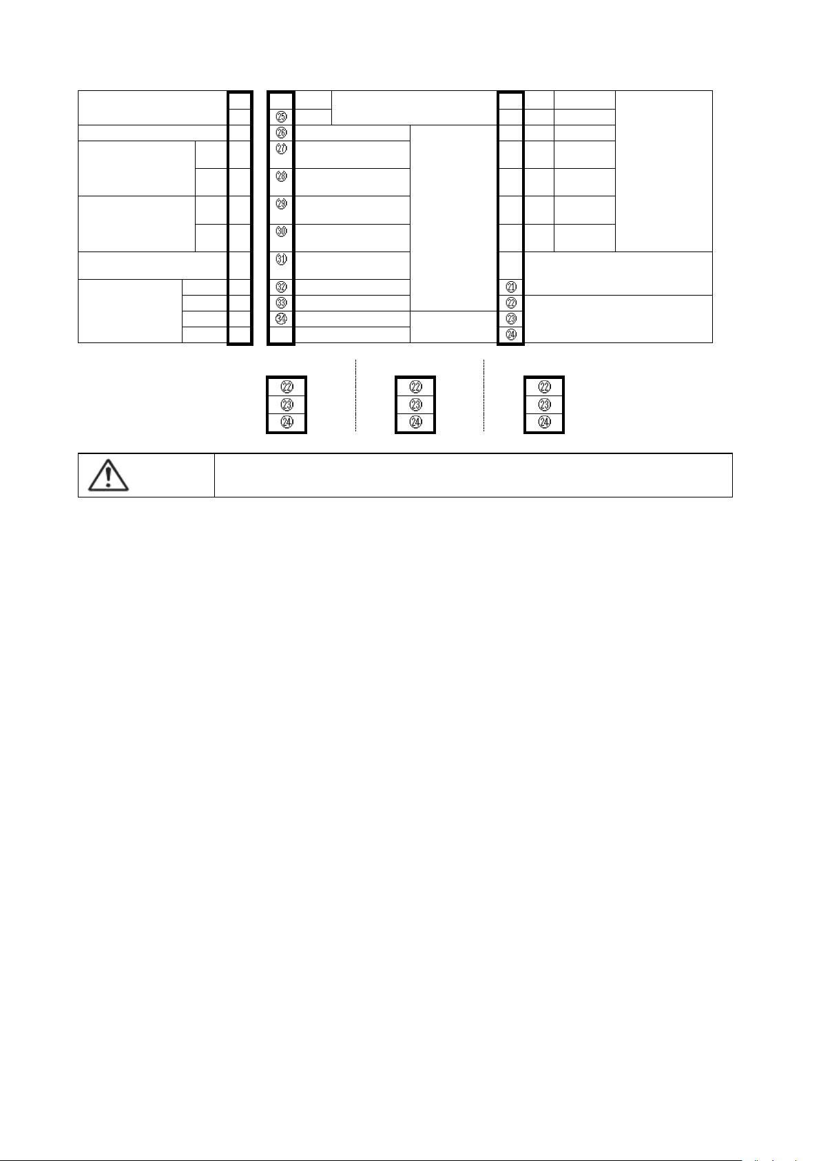
5.14 Caution
Care must be used for the names with suffixes as described below:
*1: Setting related to steps in a run cannot be changed.
*2: No change is possible during a run.
*3: SAVE (all settings writing) is performed.
6. Measurement range and indicator resolution
- 28 -
Page 29

7. List of models
TTM-339-□ □-□□□□□□
① ② ③
Symbol
Item
Description
Size
96 x 96
Input
Multi-input: Thermocouple, resistance temperature detector, voltage and current
①
OUT1 (Primary
control)
R
Relay contact output
P
SSR drive voltage output (0 to 12 VDC)
I
Current 4 to 20 mADC output
②
OUT2
(Primary/secondary
control)
N
None
R
Relay contact output
P
SSR drive voltage output (0 to 12 VDC)
I
Current 4 to 20 mADC output
③
Option
A
Relay contact outputs EV1 to EV3 *1
B
Relay contact output END signal output
C
Open collector outputs TS1 to 4, TIME, EV4 output *2
D
CT input *3
E
No-voltage contact input
M
Communications RS-485
T
English version panel sheet
*1 No EV3 if a relay contact output is selected for OUT1. No EV2 if a relay contact output is selected for OUT2.
*2 No EV4 if a relay contact output is selected for OUT1 or OUT2.
*3 Select I for OUT1 or OUT2. This CT is of a type to limit the operation amount but not to detect disconnection. It is
effective for the PID control of the heat control.
Memory element
EEPROM
Input/Output isolation
Between Output area(control, event output) and Input area (process, CPU) and Power source
Power voltage
100 - 240 VAC, 50/60 Hz (Allowable voltage range: 85 - 110 %)
Power consumption TTM-339
10VA(AC264V)
Momentary power cut off
Within 1 cycle(20mS), Cut 100% power off on 100V AC at max. power consumption
Isolation resistance
Measurement terminal - case 500 VDC, 20 M.
Power terminal - case 500 VDC, 20 M.
Withstand voltage
Measurement terminal - case 1500 VAC for a minute.
Power terminal - case 500 VAC for a minute.
Operation
environment
Temperature
0~50℃
Humidity
20 - 90 %RH (no dew condensation allowed)
Set angle
Datum surface ±10 degrees
Vibration
0~0.2G
Transportation/sto
rage condition
Temperature
-20 - +70 °C (no freeze or dew condensation allowed)
Humidity
5 - 95 %RH (no dew condensation allowed)
PV input area
Input type
Thermocouple
K,J,T,E,R,S,B,N,U,L,WRe5-26,PR40-20,PLⅡswitchable.
Effect of outer resistance approx.0.5μV/Ω
Indicating over, when wire is disconnected
R.T.D.
Pt100, JPt100 switchable
Allowable lead wire resistance 10Ωor less(per wire)
Indicating over, when wire is disconnected(for all of A, B and b)
Sampling time
0.2 sec. (same as output change frequency)
PV correct.
-199.9~999.9℃( ) or -199~999℃( )
Display/
Setting
Display type
PV/character
5-digit 7 segment LCD(back light colors of red, green and orange) letter height
20mm
Set value
5-digit 7 segment LCD(back light colors of red) letter height 8mm
Status
1-digit 6 segment LCD(back light colors of red)
Pattern display
2-digit 7 segment LCD(back light colors of green)
Step display
2-digit 7 segment LCD(back light colors of green)
8. STANDARD SPECIFICATIONS
8.1 General specifications
8.2 Standard and performance
- 29 -
Page 30

Display/
Setting
Display type
LCD lamp red
15 pcs RUN,OUT,EV1,EV2,EV3,EV4、TS1,TS2,TS3,TS4,TIME,AUTO,MAN
U,AT,END
LCD lamp green
2 pcs PTN,STP
Accuracy of
Indication /Set
ting
Thermocouple
Thermocouples of K, J, T, E, R, S, B and N
Either larger ± (0.3 % + 1 digit) or ± 2 °C of the indicated value
Note: ± 3 °C for -100 to 0 °C and ± 4 °C for -200 to -100 °C
No specification for 400 °C or lower for B thermocouple
* In standard environment conditions (23 ± 10 °C)
Thermocouples of U and L:
Either larger ± (0.3 % + 1 digit) or ± 4 °C of the indicated value
± 6 °C for 0 °C or lower
WRe 5-26
Either larger ± (0.6 % + 1 digit) or ± 4 °C of the indicated value
PR 40-20
± 9.4 °C ± 1 digit No accuracy specified for lower than 800 °C
PL II
Either larger ± (0.3 % + 1 digit) or ± 2 °C of the indicated value
R.T.D.
Either larger ± (0.3 % + 1 digit) or ± 0.9 °C of the indicated value
* In standard environment conditions (23 ± 10 °C)
Voltage
± 0.3 % ± 1 digit of FS * In standard environment conditions (23 ± 10 °
C)
Only 0-10mV, ± 0.5 % ± 1 digit of FS
Current
± 0.3 % ± 1 digit of FS * In standard environment conditions (23 ± 10 °
C)
Setting method
Set all parameters with the front keys.
Lock
functions
Normal screen lock setting, Pattern No. setting mode lock setting, Alarm temperature setting mode lock setti
ng, PID setting mode lock setting ,26 kinds.
Control/
output
Control type
Select from ON/OFF control, PID control .
Power ON
Relay contact output, SSR drive voltage output Approx. 4 sec output 0%.
4~20mA DC output Approx. 4 sec. 1mA output
PV abnormal
Relay contact output, SSR drive voltage output : output: 0% output (output OFF)
4~20mA DC : output: 0%
Standards
Relay contact output : contact specification 1a contact capacity 250VAC 3A(resistance load).
SSR drive voltage output: OFF time; 0V DC ON time; 12V DC Loaded resistance over 600Ω.
(It may vary according to a calculation with SSR inner resistance.)
4~20mA DC output: Output current 4~20mA DC Loaded resistance below 600Ω.
Output range:DC2.4~21.6mA
Communication
Loader
communication
Communication specification : TTL level
Network: point to point (1 vs 1 station)
Communication distance : Use TOHO loader cable.
Address : 1 - 99 stations
Program sect
ion
No. of patterns
No. of steps
No. of patterns 15max
No. of steps 99max * The maximum No. varies depending on the selected
Step time
0 to 99 hours 59 minutes
Time accuracy
(0.5% + 0.5 seconds) of setting time
running times
0 - 99 times (0 for infinite number)
wait
Wait zone : 0.0 to 999.9C Wait time : 0 to 99 hours 59 minutes
Option
Event output
Relay contact output : contact specification 1a contact capacity 250VAC 1A(resistance load).
No-voltage contac
t input
OFF time voltage: 6V DC ON time current: 6mA DC
Minimum input time: 200mSEC and over
Communication
Communication specification : RS-485
network : Multidrop(1:31)
Communication distance : 500 m
Address : 1 - 99 stations * For MODBUS setting, 1 - 247 stations
- 30 -
Page 31

9.MAINTENANCE AND INSPECTIONS
Troubles
Check points
Display does not come out.
Is instrument correctly inserted in the case?
Are power terminals correctly connected?
Is power sufficiently supplied?
Unable to start
Is the process value appropriate for any of the run steps after selecting PV Start?
Insufficient control
Value setting of PID constant, control sensitivity and fuzzy strength all proper?
Temperature does
not increase(or decrease)
Is output terminal correctly connected?
Is control type correctly set up?
Step Forward/Reverse is
not effective with Key
operation
The External Drive Signal Selection may be switched ON?
When the External Drive Signal Selection is set to ON, Step Forward/Reverse with key operation
will not be effective.
Name
Display
Occurrence conditions/Release method
Memory error
Occurrence condition: Occurs if the recorded setting value is abnormal.
Release method: Repair the board.
Temperature input circuit
error
Occurrence condition: Occurs if the temperature input circuit is abnormal.
Release method: Repair the board.
Auto tuning error
Occurrence condition: Occurs if the temperature sensor disconnected or the temperature
input is out of the display range, or an auto tuning does not end
after 3 hours elapsed from its start.
Release method: Use either key for release.
Secondary machine
communications error
Occurrence condition: Occurs if communications with the secondary machine is
abnormal.
Release method: Use the RESET key for recovery.
FRAM error
Occurrence condition: Occurs if FRAM (memory element) is abnormal.
Release method: Use either key for release. Repair the substrate if re-occurs.
Temperature input upper
limit error
Occurrence condition: Occurs if the temperature sensor disconnected or the temperature
input is beyond the display range upper limit.
Release method: Check the temperature sensor connection; restored if the
temperature input returns to within the normal range.
Temperature input lower
limit error
Occurrence condition: Occurs if the temperature input is below the display range lower
limit.
Release method: Check the temperature sensor connection; restored if the
temperature input returns to within the normal range.
LOC Indication
Occurrence Condition: It happens when changing parameter is attempted during Key Lock
Release method: Release Key Lock.
If any of the troubles still exists after following the above instruction, or for any other cases, contact our Sales Department.
Display methods, etc. as follows are used at an abnormality.
The PV digit turns to red at occurrence of an abnormality. The lower row turns off..
- 31 -
Page 32

TOHO ELECTRONICS INC.
WEB.site http://www.toho-inc.com E-mail overseas@toho-inc.co.jp
Head office:1-13-21,Tanashioda,Tyuuohku,Sagamihara Kanagawa 252-0245 Japan
TEL +81-42-777-3311 FAX +81-42-777-3751
(C)2010 TOHO ELECTRONICS INC. ALL rights reserved.
48-8364-F
- 32 -
 Loading...