

Page 1

Digital Controller
TTM-200 series
User’s Manual
TOHO ELECTRONICS INC.
Page 2
User’s manual for digital controller TTM-200 series
Danger
Improper handling of the
equipment may cause fatality or
serious injury for an impending
reality.
Caution
Improper handling of the
equipment may cause injury or
physical damage on it.
Warning
Improper handling of the
equipment may cause fatality or
serious injury.
Reminder
Care should be taken for
ensuring safety.
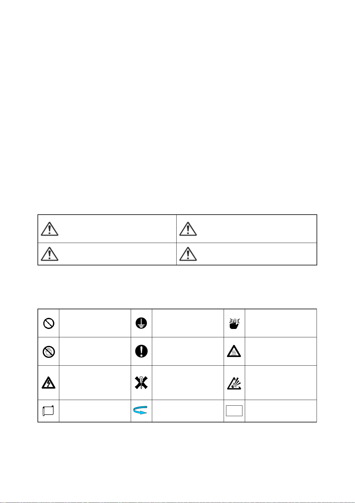
General caution, warning or
prohibition without
particularity
Instruction on ground
connection for the
equipment with safety
grounding terminals
Hazard of pinched fingers
on a particular portion of the
equipment
Possible injury caused by
touching a particular portion
of the equipment under
specific conditions
Unspecific behaviors of
general users
Hazard of injury due to high
temperature under specific
conditions
Hazard of an electric shock
under specific conditions
Hazard of injury such as an
electric shock due to
disassembling or
modification of the
equipment
Hazard of burst under
particular conditions
Supplementary explanation
Designation of reference for
explanation
Care for use or operation
Note
Introduction
Thank you for purchasing Toho Electronics’ TTM-200 series.
Before using the products, thoroughly read this manual for a better understanding of them.
Ensure to store this manual and use it whenever needed.
Precautions on the use of the products
Ensure to read this manual before using the equipment.
Take care to understand the following for the safe use of the equipment.
Ensure this manual to be in hands of a person using the equipment.
★ Precautions on safety
Alarms are defined and categorized into either one of four groups in this manual, depending on degrees of
importance or risk in terms of the safe use of the equipment or prevention of accident or damage on the
equipment. For each alarm, symbol is assigned as shown below.
★ Alarm symbols
An alarm categorized in the group of Caution may still yield to serious result, depending on circumstances.
Any symbol for the four groups intends to raise user’s attention for important description. Carefully observe
it.
★ Other symbols
48-7009-E i
Page 3
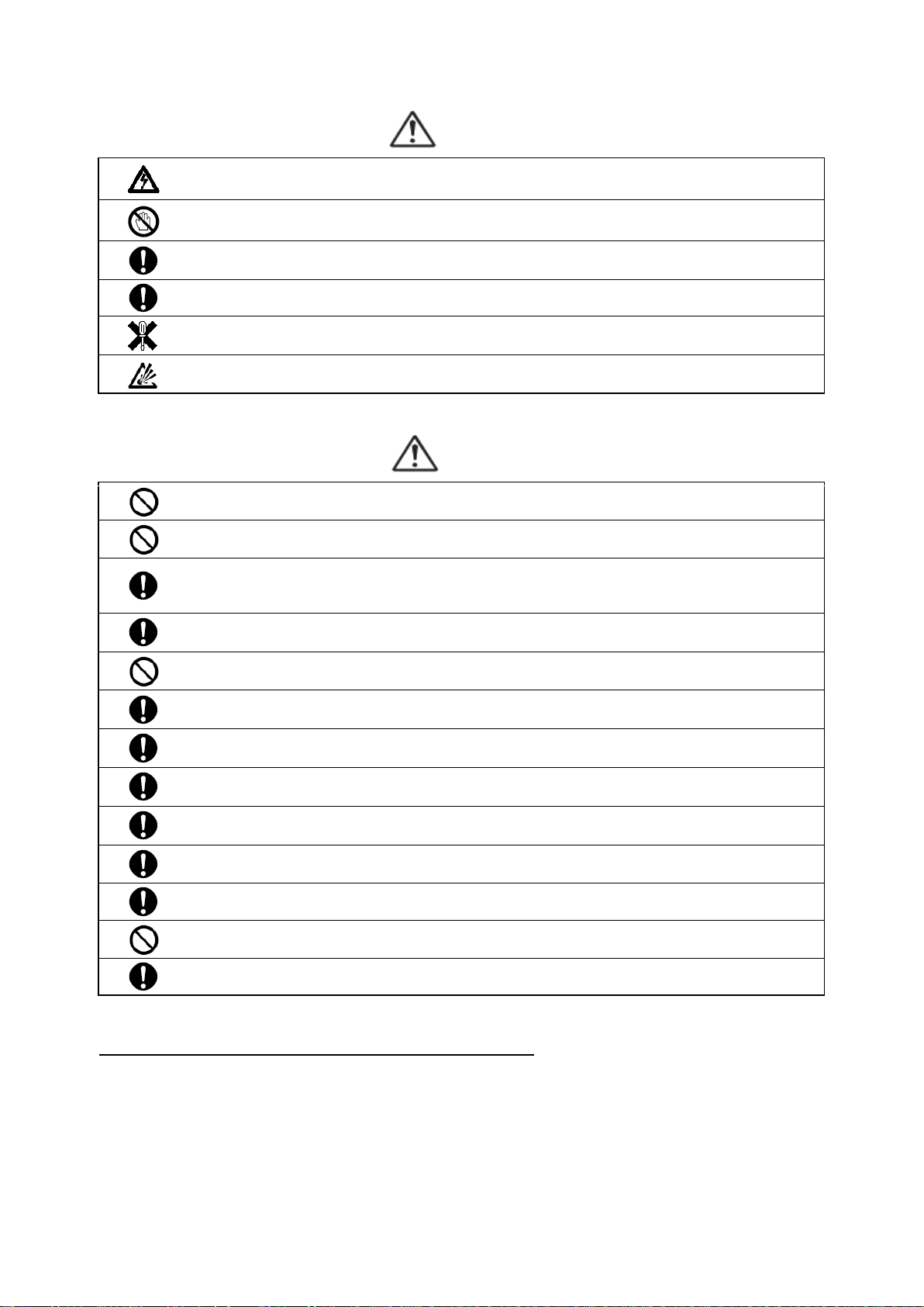
Warnings
Improper wiring to the equipment may cause a failure, such as fire. Upon completion of wiring,
ensure to verify the proper wiring before turning on electricity.
Do not turn on electricity until all wiring is complete. Do not touch portions of high voltages such as
power supply terminals, as an electric shock may be resultant.
Install appropriate protective circuits externally if a failure or abnormality of the equipment may
seriously affect related systems.
Do not use the equipment out of the specified range, as it may fail or catch fire.
Do not under any circumstance to modify or disassemble the equipment, as a failure may be caused,
resulting fire or an electric shock.
Do not use the equipment in ambience of flammable or explosive gases.
Do not use the vacant terminals for wiring.
Do not use a pointed object to operate keys.
Do not turn on the power supply until wiring is fully complete in order to prevent an electric shock,
failure or malfunctioning. For replacing a component connected on the equipment, ensure to turn off
the power supply. For turning back on the power supply, do so after all wiring is complete.
Ensure not to trap heat in the space surrounding the equipment in order to provide sufficient heat
release.
Do not put a metal piece or similar inside the equipment. A fire, an electric shock or failure may be
caused.
The equipment is designed for instrumentation. For its use in environments of high voltages or
intense noises, take appropriate measures on the side of user’s equipment.
The equipment is designed for controlling physical values, such as temperatures, on general industrial
facilities. Do not use it for subjects of control that may seriously affect human life.
Turn off the power supply before cleaning the equipment, and wipe it with a soft dry cloth. Do not use
thinners, as they may cause deformation or discoloration of the equipment.
The equipment may cause radio disturbances in domestic settings. User is required to take
appropriate measure.
Ensure to tighten terminal screws at specified torque. Insufficient tightening the screws may cause
an electric shock or fire.
Ensure to observe precautions listed in this manual for the use of the equipment.
Reprinting or duplicating this manual is prohibited.
This manual may be revised without prior notice.
Cautions
Precaution regarding Export Trade Control Ordinance
Investigation on client or application by an appropriate party is required so that the equipment is not used for
mass destruction weapons and such (military application, military facilities, etc.).
48-7009-E ii
Page 4
Notation convention in this manual
Abbreviation
Term
PV
Present value
SV
Setting value
AT
Auto-tuning
ENT
Determined
MV1
Primary operating amount
MV2
Secondary operating amount
CT
Current transformer
AI
Remote SV input
0 1 2 3 4 5 6
7 8 9
Minus
Period
Slash
A B C D E F G
H I J K L M N
O P Q R S
T(t)
U
V W X Y Z n v
★ Summary notation
Abbreviations in alphabetical characters are used for the diagrams and text in this manual. Some major
examples are as follows.
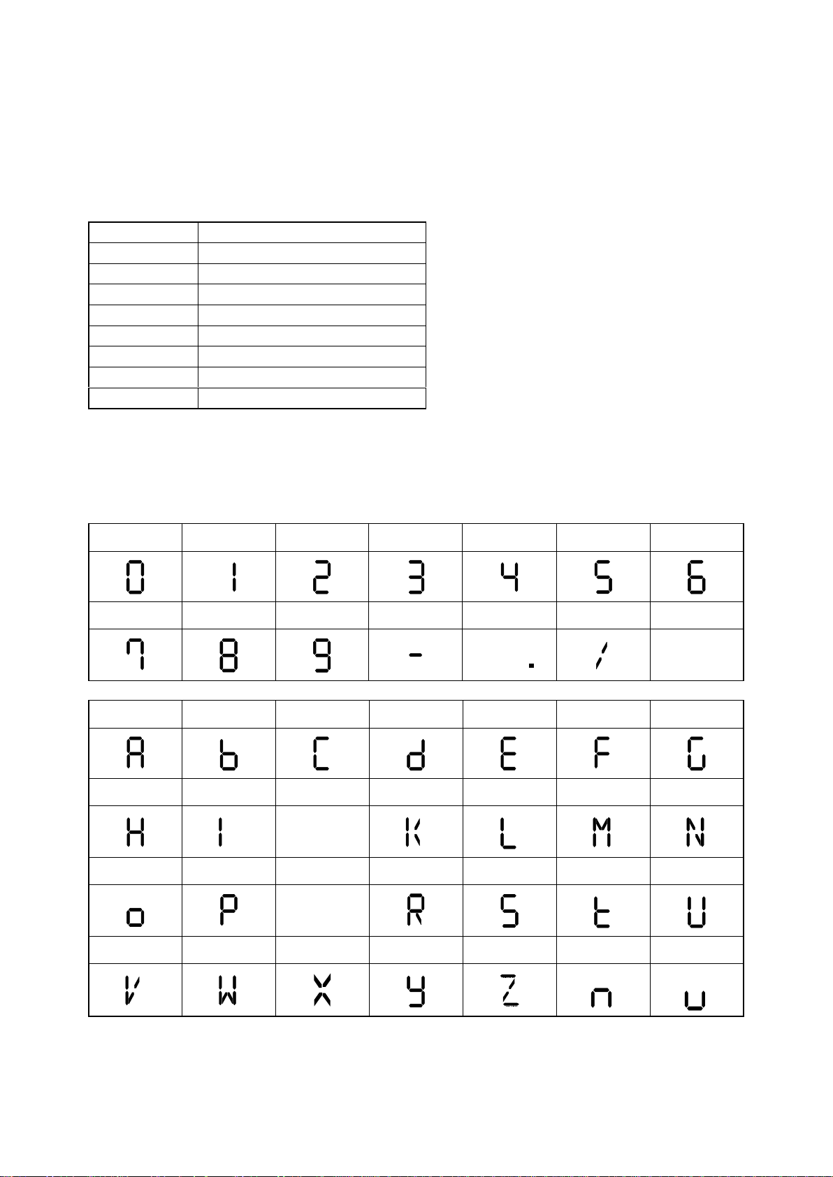
★ Notation of characters
For parameters and settings, numeric and alphabetic characters are inscribed as follows. (For initial setting, a
character is comprised of eleven segments.)
48-7009-E iii
Page 5

Contents
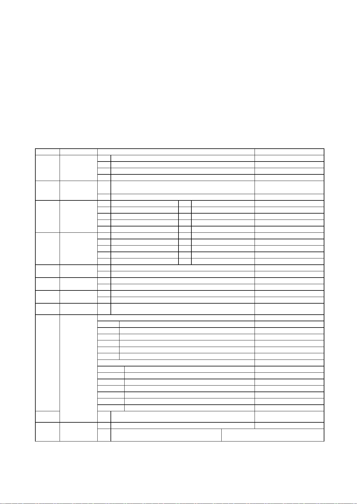
1. Overview
Outline of TTM-200 series is described, in terms of features, model configuration (codes), names of
components and functions. Thoroughly read this chapter prior to the first use.
This manual is applicable for the product of which main body has a firmware of Ver3.xx or later.
The previous manual must be used if the main body firmware of Ver2.xx or earlier is used.
1.1 Feature ..................................................................................................................................................... 1-2
1.2 Checking the product ............................................................................................................................... 1-3
1.3 Model table .............................................................................................................................................. 1-3
1.4 Names of parts and components .............................................................................................................. 1-4
1.5 Input/output function and essential functions .......................................................................................... 1-7
1.6 Basic flow of setting ...............................................................................................................................1-11
2. Installation
How to install TTM-200 series and precautions on the installation are described.
Read this chapter prior to the installation.
2.1 Precautions on installation ....................................................................................................................... 2-2
2.2 How to install or remove the equipment .................................................................................................. 2-3
2.3 Outside dimensions and panel cutting dimensions .................................................................................. 2-4
3. Wiring
Wiring of TTM-200 series is described.
Read this chapter prior to the wiring.
3.1 Precautions on wiring .............................................................................................................................. 3-2
3.2 Terminal arrangement .............................................................................................................................. 3-3
3.3 Wiring to each terminal ........................................................................................................................... 3-7
3-4 Examples of wiring ................................................................................................................................ 3-15
4. Basic functions
Basic operation (setting method) of TTM-200 series is described.
4.1 Flow of setting mode ............................................................................................................................... 4-2
4.2 Basic operation ........................................................................................................................................ 4-4
4.2.1 Switchover of parameters (flow as a whole) .................................................................................. 4-4
4.2.2 Description of setting item selection screen ................................................................................. 4-19
4.2.3 Setting of input types ................................................................................................................... 4-20
4.2.4 Setting of key functions ............................................................................................................... 4-21
4.2.5 How to set the SV limiter setting ................................................................................................. 4-22
4.2.6 How to set control types ............................................................................................................... 4-23
4.2.7 How to set outputs ........................................................................................................................ 4-25
4.2.8 How to set priority screens ........................................................................................................... 4-26
4.2.9 Switchover to the blind setting mode ........................................................................................... 4-27
4.2.10 Switchover to the ON/OFF control .............................................................................................. 4-29
5. Operation
Operation, often-used setting items, how to set each function and description of the function of TTM-200
series are described.
5.1 Precautions on operating the equipment .................................................................................................. 5-2
5.2 Operating monitor display ....................................................................................................................... 5-3
5.2.1 Operating amount monitor: SET 04 (control setting mode) ........................................................... 5-3
5.2.2 Timer remaining time monitor: Run mode ..................................................................................... 5-3
5.2.3 Temperature measurement monitor: Run mode ............................................................................. 5-3
5.2.4 CT monitor: SET 12 (CT setting mode) ......................................................................................... 5-3
48-7009-E iv
Page 6

5.3 How to set run settings............................................................................................................................. 5-4
5.3.1 Target value (SV) setting ................................................................................................................ 5-4
5.3.2 ON/OFF control setting.................................................................................................................. 5-7
5.3.3 PID control setting ......................................................................................................................... 5-9
5.3.4 Heating/cooling PID control setting ............................................................................................. 5-13
5.3.5 Indicator setting ............................................................................................................................ 5-15
5.3.6 Excessive ascent prevention unit (alarm unit) setting .................................................................. 5-17
5.3.7 Event setting ................................................................................................................................. 5-18
5.3.8 How to set MD/READY .............................................................................................................. 5-20
5.4 How to set each function and description of function ........................................................................... 5-22
5.4.1 Auto-tuning (AT) function ........................................................................................................... 5-22
5.4.2 Self-tuning function ..................................................................................................................... 5-25
5.4.3 Mode/manual function ................................................................................................................. 5-27
5.4.4 Bank function ............................................................................................................................... 5-28
5.4.5 Timer function .............................................................................................................................. 5-31
5.4.6 Loop abnormality function ........................................................................................................... 5-38
5.4.7 Current transformer (CT) abnormality function ........................................................................... 5-40
5.4.8 Position proportional control ........................................................................................................ 5-45
5.4.9 Concurrent temperature ascent function ...................................................................................... 5-46
5.5 Explanation of the program run function ............................................................................................... 5-47
5.5.1 Operation flow of the program run .............................................................................................. 5-48
5.5.2 SET 21 program function setting ................................................................................................. 5-49
5.5.3 SET 21 program function setting screen ...................................................................................... 5-52
5.5.4 SET 22 program setting ............................................................................................................... 5-53
5.5.5 SET 22 program setting screen .................................................................................................... 5-55
5.5.6 Explanation of the screen display and operation of a program run .............................................. 5-56
5.5.7 Complementary explanation of the program run ......................................................................... 5-61
5.6 Explanation of the bank automatic switching function .......................................................................... 5-70
5.6.1 Bank automatic switching setting ................................................................................................ 5-71
5.6.2 SET 23 bank automatic switching function setting mode setting screen ..................................... 5-73
5.6.3 Complementary explanation of the bank automatic switching function ...................................... 5-74
6. Parameters
Various parameters of TTM-200 series are described in terms of their functions.
Read this chapter prior to their settings.
6.1 Input 1 type setting .................................................................................................................................. 6-2
6.2 Remote SV input type setting .................................................................................................................. 6-8
6.3 Function key function setting ................................................................................................................ 6-12
6.4 Control function setting ......................................................................................................................... 6-14
6.5 Output (from OUT 1 to OUT 7) type setting ......................................................................................... 6-49
6.6 Current transformer (CT) setting ........................................................................................................... 6-57
6.7 DI setting ............................................................................................................................................... 6-59
6.8 Timer function setting ............................................................................................................................ 6-62
6.9 Communication function setting ............................................................................................................ 6-65
6.10 Initial setting .......................................................................................................................................... 6-67
6.11 Priority screen setting ............................................................................................................................ 6-71
6.12 Bank function setting ............................................................................................................................. 6-72
6.13 Program function setting ........................................................................................................................ 6-73
6.14 Program setting ...................................................................................................................................... 6-77
6.15 Bank automatic switching function setting ............................................................................................ 6-80
7. Appendix
Product specification, errors (troubles) and parameter setting table of TTM-200 series are described.
7.1 Product specifications .............................................................................................................................. 7-2
7.2 Accessories .............................................................................................................................................. 7-9
7.3 Error (abnormality) display ................................................................................................................... 7-10
7.4 Troubleshooting ......................................................................................................................................7-11
7.5 Setting list .............................................................................................................................................. 7-13
48-7009-E v
Page 7

1. Overview
Features of products, confirmation of products, and model coding and the name of each component or part are
described in this chapter.
1.1 Feature .................................................................................................................................................... 1-2
1.2 Checking the product ............................................................................................................................. 1-3
1.3 Model table............................................................................................................................................. 1-3
1.4 Names of parts and components ............................................................................................................. 1-4
1.5 Input/output function and essential functions ........................................................................................ 1-7
1.6 Basic flow of setting ..............................................................................................................................1-11
48-7009-E 1-1
Page 8

1.1 Feature
★ Improved controllability due to new PID algorithm
(1) Time required to stabilize after start of control has been reduced (compared to Toho’s other models).
(2) Jumpless control function is supported, where post-disturbance overshoots are suppressed.
(3) Selection can be made from three types of PIDs.
(PID auto-tuning with the overshoot suppression function is set as factory default.)
★ Full multi-input
Thermocouples (13 types), resistance temperature detector (2 types), voltage (5 types) and current (one
type) are achieved as input specifications on a single unit. Their changes are possible through setting
changes of parameters. (“K thermocouple” is set as factory default)
★ Compact-sized with dimension of 55 mm (TTM-204) or 65 mm (other than TTM-204) in depth
★ Sampling cycle of 200 ms
★ Loader communication function
Best suited for setting various parameters
Dedicated cable: Option (with charge) (See page 7-9 for specifications.)
Dedicated software: Option (free-of-charge)
★ Blind function and priority screen for a simplified operation
Blind function: Among multiple parameters, only those needed can be displayed.
Priority screen: By transferring the necessary parameter screen to the operating mode screen, indication as
well as the setting would be possible without calling the parameter screens. (max. 20 screens)
★ The valve position proportional control is made possible without feedback resistance.
★ Bank function
Each process value (such as SV, PID constants) which varies in each process can be set at every bank,
enabling the setting changes according to the content of the process. (max. 8 points)
★ Simple timer function
Control of “start or stop of control after predetermined time has elapsed” can be done on a single unit.
The independent use of timer is also allowed. (Independent 3 points)
★ Protective structure In compliance with IP66 or equivalent (TTM-204 only)
★ Applicable to various instrumentation systems, using manual control
★ Password function
★ Modification to the settings at factory default is possible.
★ Display colors of PVs (measurement values) can be changed to green, red or orange.
★ Ramp function enables the setting of gradient.
★ Soft-start function
During PID control, a limit can be applied to an operation volume for a predetermined period of time
when the power switched.
★ Delay timer function
During ON/OFF control, the control output (primary/secondary) can be done with a predetermined lag
time.
★ Program run function
A max. of 8-step program operation is possible.
★ Bank auto-switchover run function
A bank auto-switchover run is possible by using 8 banks at most.
48-7009-E 1-2
Page 9
1.2 Checking the product
Symbol
Item
Description
Remarks
①
Size
4
48 x 48
5
96 x 48
7
72 x 72
9 96 x 96
②
Color
Q
Color of case: Black
X
Color of case: Gray
Not available for 205,7,9.
③
Output 1
N
None
J
Voltage 0 - 5 VDC
R
Relay
F
Voltage 1 - 5 VDC
P
SSR drive voltage
G
Voltage 0 - 10 VDC
A
Open collector
I
Current 4 - 20 mADC
K Voltage 0 - 1 VDC
H
Voltage 0 - 10 mVDC
④
Output 2
N
None
J
Voltage 0 - 5 VDC
R
Relay
F
Voltage 1 - 5 VDC
P
SSR drive voltage
G
Voltage 0 - 10 VDC
A
Open collector
I
Current 4 - 20 mADC
K Voltage 0 - 1 VDC
H
Voltage 0 - 10 mVDC
⑤
Outputs 3
and 4
A
Open collector
Common
R
Relay contact
Common
⑥
Outputs 5
and 6
A
Open collector
Not available for 204. *1
R
Relay contact
Not available for 204. *1
⑦
Output 7
A
Open collector
Not available for 204. *3
R
Relay contact (common independent)
Not available for 204. *3
⑧
AI input
Y
Remote SV input: Only voltage and current
Not available for 204.
⑨
Option
Case of TTM-204,207
ST
CT 1,2input
*2
SV
CT 1 input, Event 2 input
*2
UV
Event 1,2 input
STW
CT 1,2input, Event 3 input
Not available for 204.*2,*3
SVW
CT 1 input, Event 2,3 input
Not available for 204.*2,*3
UVW
Event 1,2,3 input
Not available for 204. *3
Case of TTM-205,209
ST
CT 1,2input
*2
SV
CT 1 input, Event 2 input
*2
UV
Event 1,2 input
SVW
CT 1 input, Event 2,3,4 input
*2
UVW
Event 1,2,3,4 input
STUV
CT 1,2 input, Event 1,2 input
*2
STUVW
CT 1,2 input, Event 1,2,3,4 input
*2
⑩
M
Communication (RS-485)
⑪
24 V power
supply
Free power supply
L
24 VAC / 24 VDC
For models 205,207,209 are still under
development.
Prior to the use, check the following.
★ Checking the model
The model number is printed on the box and side of the product. Check that the numbers thereon
matches with the model that had been ordered.
★ Appearance
Check that no scratch or damage is present on the case, front panel or terminal block.
★ Check that accessories are included in the box. (See below for the list of the accessories.)
Mounting tool, brief operation manual and rubber packing (attached to the main frame)
1.3 Model table
TTM20
① ② ③④ ⑤⑥⑦⑧⑨⑩ ⑪
*1 Output6 is not selectable for 207
*2 CT is not selectable, if there are only analogue output.
*3 Either W (only event3) or output7 should be selected for 207.
When the option from ④ is not added, the model code is omitted. Example. TTM-205-Q-RN-M
48-7009-E 1-3
Page 10
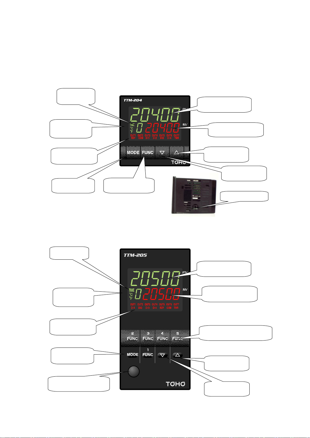
1.4 Names of parts and components
PV display
SV display
Up key
Down key
Function key
Mode key
Bank display
Unit of
temperature and
timer display
Operation display
Loader port
(Located on the bottom wall)
PV display
SV display
Function key (1 to 5)
Up key
Down key
Mode key
Operation display
Unit of
temperature and
timer display
Bank display
Loader port
■ Front panel
★ TTM-204 * The loader port is located in the bottom wall for TTM-204.
★ TTM-205
48-7009-E 1-4
Page 11
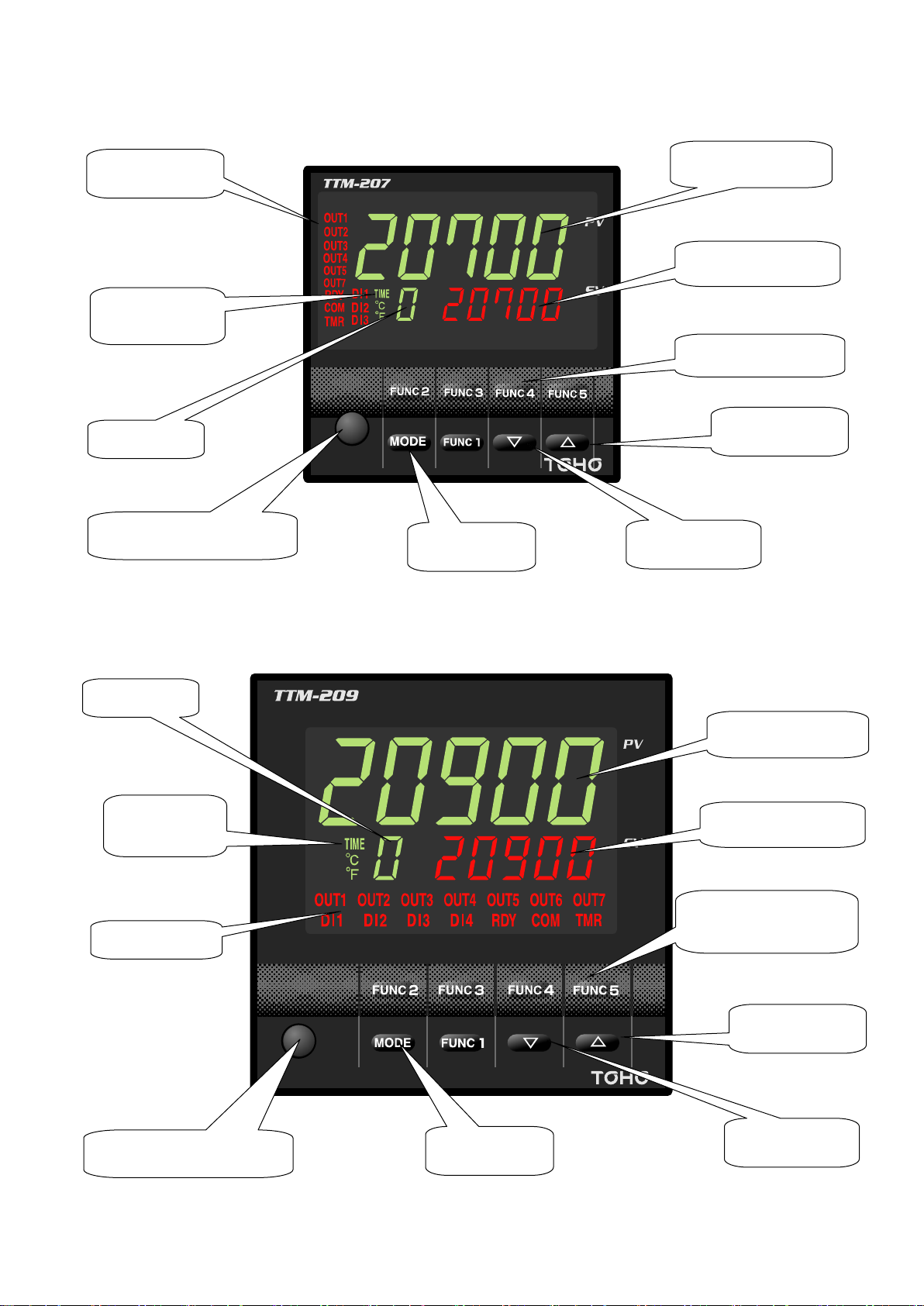
★ TTM-207
Down key
Up key
Function key
(1 to 5)
SV display
PV display
Bank display
Operation display
Unit of
temperature and
timer display
Mode key
Loader port
Bank display
PV display
SV display
Function key
(1 to 5)
Up key
Down key
Mode key
Loader port
Unit of
temperature and
timer display
Operation display
★ TTM-209
48-7009-E 1-5
Page 12

■ What the displays indicate
★ PV display Measurement value (present value) display, each character display and timer setting
time display
★ SV display Setting value (target value) display, output operating amount display, display of
setting value of each character, timer remaining time display and MVI (operating
amount) display
★ Unit of temperature The unit of temperature is displayed when setting data is for temperature. The
display is determined depending on setting for “unit of temperature” in the symbol
“C” or “F.”
Timer display Lights up when timer is set.
★ Bank display The bank selected is displayed.
★ Behaviors of the displays
OUT 1 Output 1 monitor display. Turns on when output is ON.
OUT 2 Output 2 monitor display. Turns on when output is ON.
OUT 3 Output 3 monitor display. Turns on when output is ON.
OUT 4 Output 4 monitor display. Turns on when output is ON.
OUT 5 Output 5 monitor display. Turns on when output is ON.
OUT 6 Output 6 monitor display. Turns on when output is ON.
OUT 7 Output 7 monitor display. Turns on when output is ON.
DI 1 DI 1 monitor display. Turns on when DI 1 is operating.
DI 2 DI 2 monitor display. Turns on when DI 2 is operating.
DI 3 DI 3 monitor display. Turns on when DI 3 is operating.
DI 4 DI 4 monitor display. Turns on when DI 4 is operating.
RDY RDY monitor display. Lights up when operation is in “READY (operation
halted).”
COM Communication monitor display. Blinks on and off when the communication
function is operating (in communication).
TMR Timer monitor display. Lights up when the timer function is operating.
■ Key operations
★ FUNC Function key. Used when a set function is to be executed.
★ MODE Mode key. Used when the screen is to be switched over.
Pressing it for 2 seconds changes the screen to the parameter screen.
Pressing it for 2 seconds changes the screen to the operating mode screen.
★ [△] Up key. Used for increasing setting values.
Used for changing over the input setting mode.
Holding it pressed accelerates the increase speed.
★ [▽] Down key. Used for reducing setting values.
Used for changing over the input setting mode.
Holding it pressed accelerates the reduction speed.
■ Others
★ Loader port Dedicated cables are connected for loader communication.
48-7009-E 1-6
Page 13
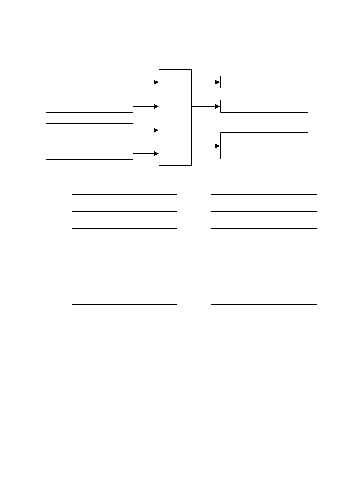
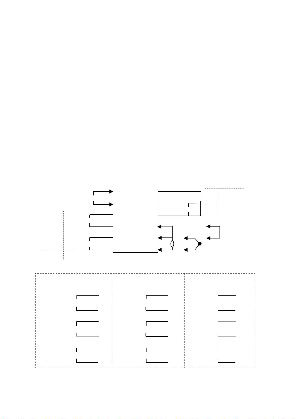
1.5 Input/output function and essential functions
Measurement value (PV) input
CT input (2 points: optional)
DI input (4 points: optional)
AI input (1 point: optional)
Output 1
Outputs 2 to 7 (optional)
Communication output (optional)
TOHO communication
MODBUS communication
Control
section
Outputs
1 and 2
Primary output
Outputs
3 to 7
Primary output
Secondary output
Secondary output
Event output
Event output
RUN output
RUN output
RDY output
RDY output
Timer 1 output
Timer 1 output
Timer 1 ON delay output
Timer 1 ON delay output
Timer 1 OFF delay output
Timer 1 OFF delay output
Timer 1 ON+OFF delay output
Timer 1 ON+OFF delay output
Timer 2 output
Timer 2 output
Timer 2 ON delay output
Timer 2 ON delay output
Timer 2 OFF delay output
Timer 2 OFF delay output
Timer 2 ON+OFF delay output
Timer 2 ON+OFF delay output
Timer 3 output
Timer 3 output
Timer 3 ON delay output
Timer 3 ON delay output
Timer 3 OFF delay output
Timer 3 OFF delay output
Timer 3 ON+OFF delay output
Timer 3 ON+OFF delay output
Transmission output
End output (during program run) *1
End output (during program run)
Input and output functions are described. See corresponding pages for setting each function.
Assignment of outputs
*1: Selectable only for a program run.
48-7009-E 1-7
Page 14
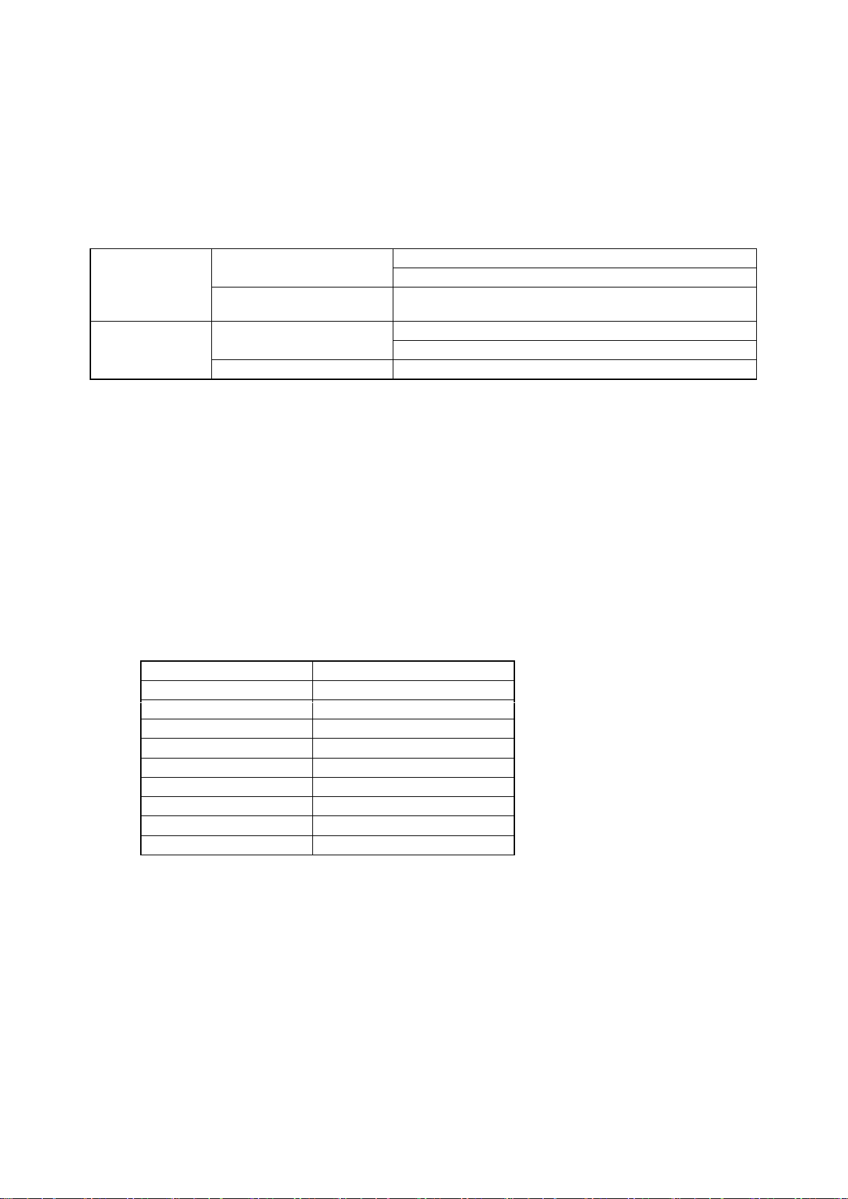
■ Input section
Temperature input
Thermocouple
K, J, T, E, R, S, B, N, U and L
WRe 5-26, PR40-20 and PLII
Resistance temperature
detector
Pt 100 and JPt 100
Analog input
Voltage
0 - 1 VDC, 0 - 5 VDC, 1 - 5 VDC
0 - 10 VDC, 0 - 10 mVDC
Current
4 - 20 mADC
Close
Active
Bank switchover
Bank switchover
MD
READY
AUTO
MANUAL
Reverse operation
Forward operation
AT stop
AT start
Timer stop
Timer start
Step feed *1
Pause *1
Interlock *1
* The following types of inputs can be selected in the input section: measurement value input (1 point),
CT input (2 points), DI input (4 points) and AI input (1 point).
Selectable points depend on models. See the model selection table.
★ Measurement value input
* The input of the controlled objects is selectable with a single unit using parameter setting.
*The K thermocouple is set as factory default.
★ CT input (optional)
* Heater disconnection failure is detected by CT (current detector) when the heater disconnection alarm
is effective.
* Max. 2 points are selectable (to be designated at order placement).
For models TTM-204 and 207, a single point for the CT input is provided when a single point for the
DI input is selected.
* Usable CT is “CTL-6-P-N-(S).” (For product specification, see page 7-9.)
* CT input is not selectable for analog output.
★ DI input (optional)
* The following functions can be executed with DI (digital) input.
The DI Input is an external no-voltage contact signals.
* List of functions due to DI
*1: Selectable only for a program run.
Close: Contact signal OFF
Active: Contact signal ON
* Max. 4 points are selectable (to be designated at order placement).
Up to 2 points are selectable for TTM-204.
DI 3 and DI 4 inputs are not selectable when input 7 is selected for TTM-207.
DI 2 input is to be selected when CT 1 input is selected for TTM-204 and 207.
★ AI input (optional)
* Voltage and current inputs only. (Voltages of 0 - 10 mV are excluded.)
48-7009-E 1-8
Page 15

■ Output section
Relay contact
250 VAC, 3 A (resistance loads) and 1a contact
Voltage for SSR drive
0 - 12 VDC (load resistance: 600 or greater)
Open collector
24 VDC, 100 mA (load current)
Voltage
0 - 5 VDC, 1 - 5 VDC and 0 - 10 VDC
(resistance loads: 1 k or greater)
0 - 1 VDC and 0 - 10 mVDC (load resistance: 500 k or greater)
Current
4 - 20 mADC (load resistance: 600 or less)
Relay contact
250 VAC, 1 A (resistance loads) and 1a contact
Open collector
24 VDC, 100 mA (load current)
Output 1
Output 2
Output 3
Output 4
Output 5
Output 6
Output 7
TTM-204
TTM-205
TTM-207
TTM-209
* The number of outputs is 7 at most, which can be assigned individually for control output, event
output, RUN/RDY output, timer output and transmission output.
(Assignment of outputs is to be designated at order placement.)
★ Output (OUT) 1 and output (OUT) 2
* Target connection of output can be set.
Primary output, secondary output, event output, RUN output, RDY output, timer 1 output, timer 2
output, timer 3 output, transmission output and end output
★ Output (OUT) 3, output (OUT) 4, output (OUT) 5, output (OUT) 6 and output (OUT) 7
* Target connection of output can be set.
Primary output, secondary output, event output, RUN output, RDY output, timer 1 output, timer 2
output, timer 3 output and end output
* Some specifications are not selectable, depending on the model. Check them on the model table.
★ Selection of output types
* Outputs 1 and 2
* Outputs 3, 4, 5, 6 and 7
* Transmission output function selection
PV (measurement value) output
SV (setting value) output
MV 1 (primary operating amount) output
MV 2 (secondary operating amount) output
Control SV (setting value) output
Forward and reverse operations can be switched over for all the outputs above.
★ Selectable outputs for each model
* TTM-204: Outputs 3 and 4 are for common shared.
* TTM-207: Outputs 3 and 4 are for common shared.
When DI 3 is selected, output 7 will not be selectable.
* TTM-205 and 209: Outputs 3 and 4 are for common shared.
48-7009-E 1-9
Page 16

★ Assignment of outputs
Type of output
Output 1
Output 2
Output 3
Output 4
Output 5
Output 6
Output 7
Primary output (heating)
Secondary output (cooling)
Transmission output
Event output
Timer output
End output *1
Output assignment targets
Primary output
Secondary output
Event output
RUN output
RDY output
Timer 1 output
Timer 1 ON delay output
Timer 1 OFF delay output
Timer 1 ON+OFF delay output
Timer 2 output
Timer 2 ON delay output
Timer 2 OFF delay output
Timer 2 ON+OFF delay output
Timer 3 output
Timer 3 ON delay output
Timer 3 OFF delay output
Timer 3 ON+OFF delay output
Transmission output
End output *1
Each output can freely be assigned to output types.
○: Output assignment possible
×: Output assignment not possible
* At factory shipment, the output 1 is assigned to the primary output, and the outputs 2 to 7 to the secondary outputs.
*1: Selectable only for a program run.
★ Details on output assignment targets
Each output can individually be assigned to the following item.
*1: Selectable only for a program run.
■ Communication function
★ Communication
* This function is for communication with a host computer. (The communication function option is
required.)
* Communication protocol TOHO protocol
MODBUS protocol (RTU mode)
MODBUS protocol (ASCII mode)
* Interface RS485
* For detailed specifications, see pages 6-65 and 66.
★ Loader communication
* This communication function is for setting all data of TTM-200 series in a lump.
* In order to use the loader communication, the dedicated software for the communication must be
installed on the personal computer (PC) being used.
* To connect TTM-200 series to your PC, TOHO’s dedicated connection cable “TTM-LOADER” (sold
separately) is required.
(For the product specifications, see page 7-9.)
* When normal communication (or communication in option) is used (or active), the loader
communication cannot be used.
48-7009-E 1-10
Page 17

1.6 Basic flow of setting
Power-on
The mode changes to either “constant value run mode” or “program run mode” when four seconds are
elapsed after the power is turned-on.
Initial screen
4 sec
* Constant run value mode is established with the SET 21 operating type setting (C/P 0).
In addition, the SET 21 and 22 parameters are not displayed.
* With SET 23 bAF 1, the auto bank switchover function is selectable.
With bAF 0, the SET 23 parameters are not displayed.
Constant value run mode
* All setting item selection screens can move to the
constant value run mode screen.
MODE key for 2 seconds
The screen SET 01 appears when the run mode
screen moves to each setting item selection screen.
Each setting item selection screen
SET 01 - SET 23
* Using the ▲ /▼ key, the setting item selection
screens SET 01 to SET 23 are displayed in
sequence.
(In case of no function registered, the
corresponding screen is not displayed.)
(For bank auto-switchover, see page 6-15.)
Blind setting
screen
Parameter setting
screen in each
SET
* Each parameter setting
screen is displayed in
sequence when the MODE
key is pressed on the
parameter setting screen,
which is displayed when the
MODE key is pressed in each
setting item selection screen
(SET**). Holding the MODE
key pressed for at least 2
seconds moves each
parameter setting screen back
to the run mode screen.
Program run mode
* Program run mode is established
with the SET 21 operating type
setting (C/P 0).
* With SET 23 bAF 1,
the auto bank
switchover function
is selectable.
With bAF 0, the
SET 23 parameters
are not displayed.
MODE key for 2 seconds
Each setting item selection
screen SET 01 - SET 23
* Using the ▲ /▼ key, the setting item selection
screens SET 01 to SET 23 open in sequence.
(In case of no function registered, the
corresponding screen is not displayed.)
(For program run, see page 6-13.)
(For bank auto-switchover, see page 6-15.)
Blind setting
screen
Parameter setting
screen in each
SET
* All setting item selection screens can move
to the run mode screen.
* Each parameter setting screen
is displayed in sequence when
the MODE key is pressed on the
parameter setting screen, which
is displayed when the MODE
key is pressed in each setting
item selection screen (SET**).
Holding the MODE key pressed
for at least 2 seconds moves
each parameter setting screen
back to the run mode screen.
* A shortcut to SET 22 can be
made if FU* d is set for the
SET 3 function key function
setting.
(For details, see pages 6-12 and
13.)
* The screen moves back to the run mode screen in case of no key operation in each setting item
selection screen or parameter setting screen in each SET for about 2 minutes.
* For how to set the blind setting, see pages 4-27 and 28, the section 4-2-9 “Ba sic operation.”
48-7009-E 1-11
Page 18

2. Installation
Precautions on installation, installation method and outside dimensions are described in this chapter.
2.1 Precautions on installation ..................................................................................................................... 2-2
2.2 How to install or remove the equipment ................................................................................................ 2-3
2.3 Outside dimensions and panel cutting dimensions ................................................................................. 2-4
48-7009-E 2-1
Page 19

2.1 Precautions on installation
Warning
Ensure to turn the power supply off before beginning removal or reinstallation of the equipment in order to prevent
an electric shock or equipment failure.
★ Ambient temperature and humidity (the equipment to be used in the specified range as listed below)
(1) Temperature range: 0 - 50 °C
(2) Humidity range: 20 - 90% PH (no dew condensation allowed)
(3) Installation gradient: Base plane ± 10 degrees
★ Do not install the equipment in the following places.
(1) Where temperature abruptly changes to generate dew
(2) Where corrosive or flammable gases are generated
(3) Where water, oil, steam or chemicals are received
(4) Where vibration or noise is directly applied
(5) Where dusty or salty ambience, or many iron scraps is present
(6) Where direct sunlight is received
(7) Where circuits may negatively be affected by static electricity, noise or magnetism
(8) Where direct warm or cool air is received from an air-conditioner
★ Precautions on installation
(1) Provide sufficient space for ventilation so that the ambient temperature does not rise to 50 °C or
higher. In case that the temperature of 50 °C or higher is suspected, use a fan or air-conditioner to
cool the ambience.
Take care that no cold air flows directly on the equipment.
(2) Do not install the equipment on a device that may generate large heat, such as heater and
transformer.
(3) Install the equipment away as much distant as possible from high-voltage devices, power lines or
power equipment.
(4) Do not block off the ventilation opening on the equipment. Ensure a sufficient gap between
stacked units of equipment.
48-7009-E 2-2
Page 20
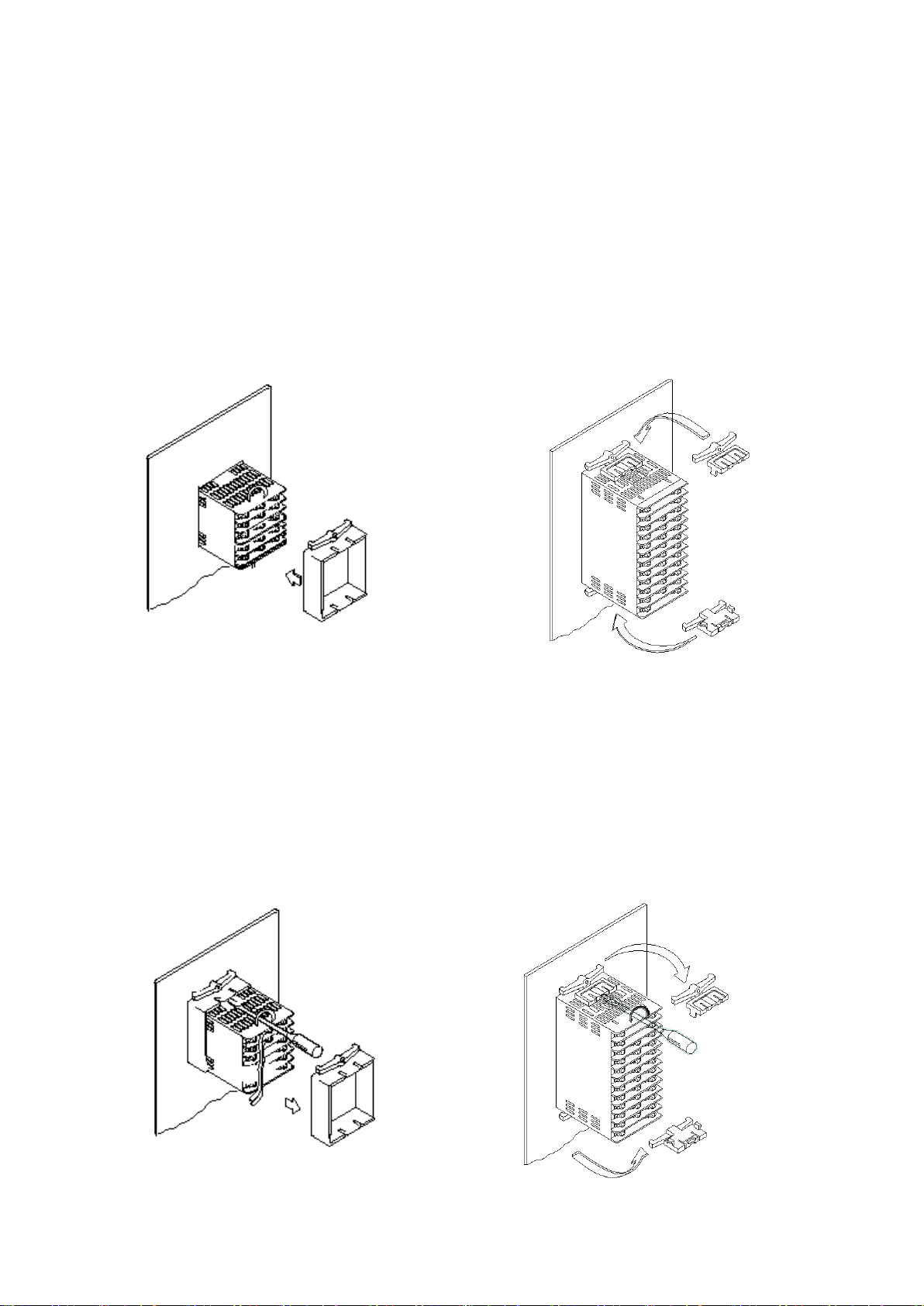
2.2 How to install or remove the equipment
★ Installation on a panel
(1) Make an opening on the panel.
(2) Insert the equipment into the opening.
(3) Install the mounting attachment from behind the panel. Ensure that the equipment is securely
fixed.
* Conduct wiring after the equipment is installed.
* Turn on the power after the wiring.
TTM-204 TTM-205/207/209
★ Removal from the panel
(1) Turn off the power.
(2) Disconnect the wiring.
(3) Insert a flat-head screw driver into the clearance formed between gabs on the equipment and
attachment. Turn the screw driver clockwise or counterclockwise to dislocate the gabs to remove
the attachment from the equipment.
(4) Remove the equipment from the panel.
* Ensure to conduct removal work after turning off the power.
TTM-204 TTM-205/207/209
48-7009-E 2-3
Page 21
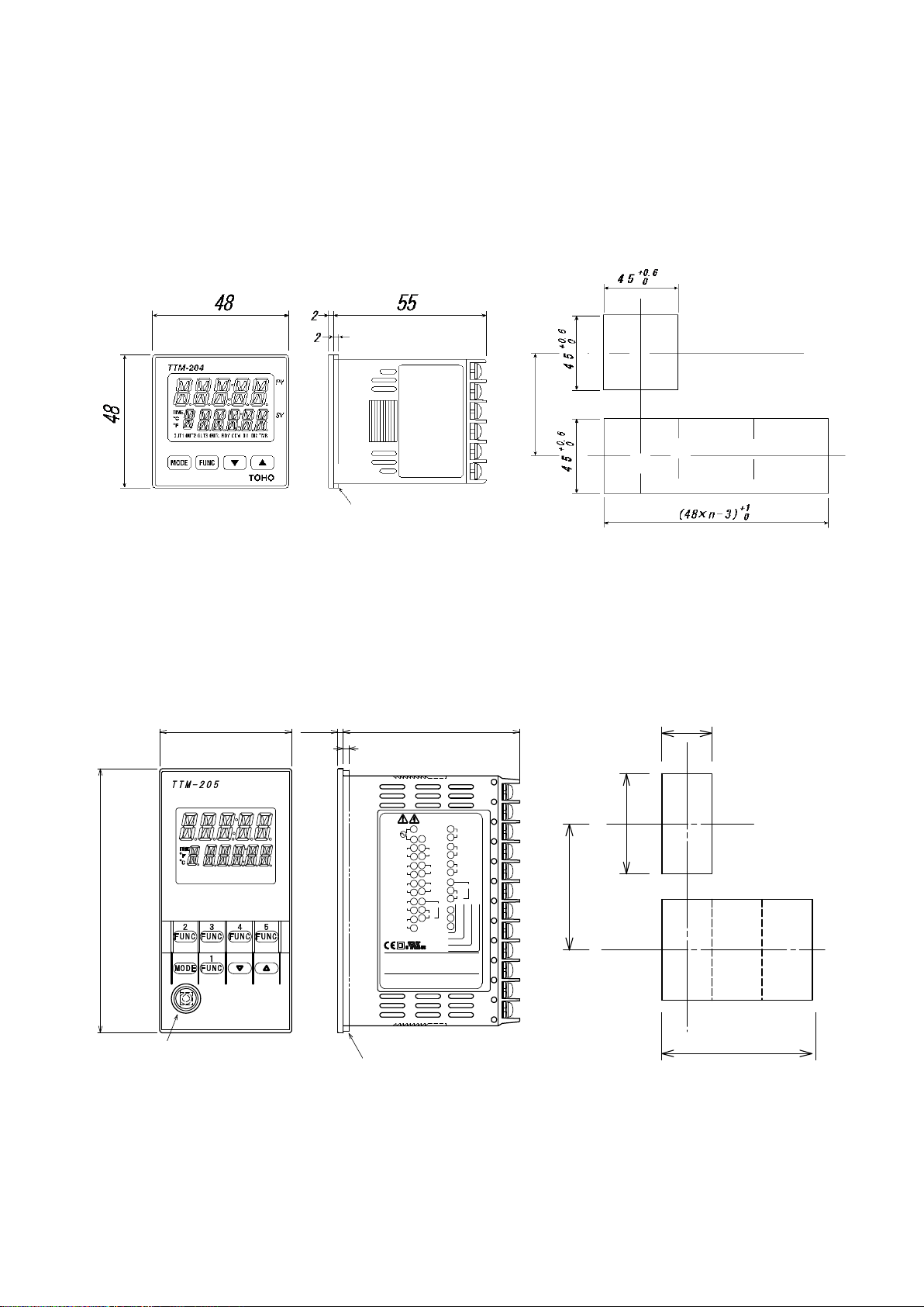
2.3 Outside dimensions and panel cutting dimensions
2
6 52
1
2
3
4
C-
NO+
OUT1
C-
NO+
C-
NO+
C-
NO+
C-
NO+
5
6
7
8
9
10
11
12
MADE INJAPAN
TOHO EL ECTRONICS INC.
++
-
DI4
-
+
DI2
34
33
32
31
30
-
+
DI1
29
28
27
26
(A)+
RS485
(B)-
+
-
DI3
+
A
I/V
RTD
TC/10mV
+ b
-
- B
24
23
22
C-
21
20
19
18
17
AI(I/V)
CT2
CT1
OUT4
C-
NO+
OUT3
NO+
+
-
16
15
14
13
SERIAL : * ****-* ****
100-240Vac~
50/60Hz
T O H O
PV
SV
DI3
OUT3
DI2
OUT2
DI1
OUT1
RDY
OUT5
COM
OUT6
TMR
OUT7
DI4
OUT4
ローダ通信端子
TTM-205-**-**********
48
9 6
OUT2
OUT5
OUT6
OUT7
25
11VA
パッキン
9 2
+0.6
0
4
5
+0.6
0
1
台取付時
n台取付時
(4 8×n - 3 )
+ 1
0
6
0 以上
When installing a single
unit of the equipment
When installing n
units of the equipment
Packing
60 or more
Packing
Loader communication
terminal
When installing a single
unit of the equipment
When installing n
units of the equipment
60 or more
Outside dimensions Panel cutting dimensions
Outside dimensions Panel cutting dimensions
48-7009-E 2-4
TTM-204
TTM-205
Page 22
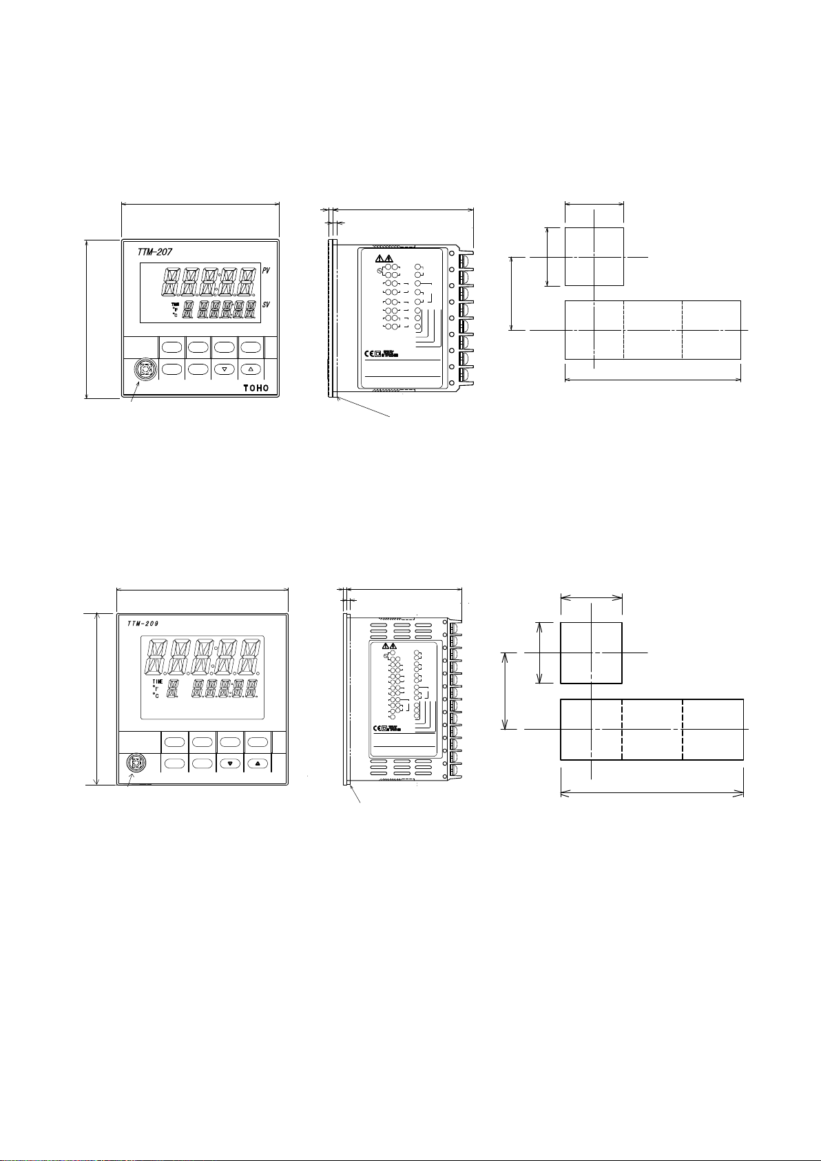
TTM-207
パッキン
2
652
ローダ通信端子
FUNC5FUNC4
MODE
FUNC2 FUNC3
FUNC1
1
2
100-240Vac~
50/60Hz
(A)+
(B)-
3
C-
+
4
NO+
-
C-
5
+
NO+
C-
6
7
-
OUT1
OUT2
DI1CT1
DI2CT2
RS485
AI(I/V)
+
-
NO+
+ b
C-
-
-
B
I/V
RTD
TC/10mV
NO+
8
+
A
NO+
C-
OUT4
OUT3
10
11
12
13
14
15
16
17
18
19
20
21
22
23
24
MADE INJAPAN
TOHO ELECTR O NICS INC.
SERIAL : *****-* * ***
TTM-207-**-**********
9
OUT5
OUT7
+
-
NO+
C-
DI3
11VA
DI3
DI2
DI1
TMR
COM
RDY
OUT5
OUT4
OUT3
OUT2
OUT1
OUT7
72
48
7 2
0
( 7 2× n - 3 )
+ 1
68
+
0
.
6
0
68
+
0
.
6
0
9
0 以上
1
台取付時
n台取付時
2
652
FUNC2
MODE
FUNC3 FUNC4 FUNC5
FUNC1
PV
SV
T O H O
OUT1 OUT2 OUT3 OUT4 OUT5 OUT6 OUT7
DI1 DI2 DI3 DI4 RDY COM TMR
ローダ通信端子
1
2
3
4
C-
NO+
OUT1
C-
NO+
C-
NO+
C-
NO+
C-
NO+
5
6
7
8
9
10
11
12
MADEINJAPAN
TOHO EL ECTRONICS INC.
++
-
DI4
-
+
DI2
34
33
32
31
30
-
+
DI1
29
28
27
26
(A)+
RS485
(B)-
+
-
DI3
+
A
I/V
RTD
TC/10mV
+ b
-
- B
24
23
22
C-
21
20
19
18
17
AI(I/V)
CT2
CT1
OUT4
C-
NO+
OUT3
NO+
+
-
16
15
14
13
TTM-209-**-**********
SERIAL : *****-**** *
100-240Vac~
50/60Hz
OUT2
OUT5
OUT6
OUT7
25
11VA
パッキン
96
96
1 2 0 以 上
9 2
+0.6
0
9 2
+0.6
0
1台取付時
n台取付時
(9 6 × n - 3 )
+1
0
Packing
Loader communication
terminal
When installing a single
unit of the equipment
When installing n
units of the equipment
90 or more
Packing
Loader communication
terminal
When installing a single
unit of the equipment
When installing n
units of the equipment
120 or more
Outside dimensions Panel cutting dimensions
TTM-209
Outside dimensions Panel cutting dimensions
48-7009-E 2-5
Page 23

3. Wiring
Precautions on wiring and arrangement of terminals are described in this chapter.
3.1 Precautions on wiring ........................................................................................................................... 3-2
3.2 Terminal arrangement ........................................................................................................................... 3-3
3.3 Wiring to each terminal ......................................................................................................................... 3-7
3-4 Examples of wiring ............................................................................................................................. 3-15
48-7009-E 3-1
Page 24

3.1 Precautions on wiring
Warning
Do not turn on the power until all wirings are complete in order to prevent an electric shock or equipment failure.
3.7
5.8
★ For inputs from a thermocouple, use the specified wires or compensating leads.
★ For inputs from a resistance temperature detector, use lead wires with small resistance and no resistance
difference is present among the 3 wires (3-wire type).
★ Provide input signal lines away from power supply lines, power lines or load lines so as not to affect input
signal lines with noise induction.
★ Wire the power supply for instruments such that they do not receive noises from the power supply for
power devices.
The use of a noise filter is recommended in case that the equipment is vulnerable to noises.
Take note of the following points when using a noise filter.
◎ Install the noise filter as close to a temperature controller as possible.
Wire the instruments in as short a distance as possible to output lines (secondary side) of the noise
filter and power terminals for the temperature controller.
◎ Isolate the noise filter input line (primary side) from its output line (secondary side).
High-frequency elements of noises may be induced, resulting in no provision of much noise
attenuation effect as expected, in case of input and output wires being close one another, such as
being bundled together or installed in a same duct or tube.
◎ Wire the grounding wire of the noise filter in as short a distance as possible.
A long grounding wire is like inserting an inductance, resulting in deteriorated high-frequency
characteristics.
◎ Before installing the noise filter, peel off the paint applied on a mounting plate of the noise filter as
★ For the power supply, use and twist wires that cause less voltage drop.
★ It takes about 4 seconds for the unit to activate after its power is turned on. Use delay relays when using
★ When using the unit with 24 V power supply, supply the power from a SELV circuit (power supply
★ When using the unit with DC24V power source, set ①-terminal to plus (+), ②-terminal to minus (-).
★ The equipment is not attached with power supply switch fuses. Separately install fuses in proximity of
★ Use crimping terminals that match the screw sizes.
★ For the communication ,use a shielded twisted pair cable.
appropriate, in order to reduce the contact resistance between the noise filter and equipment housing.
the equipment for generating signals for interlocking circuits.
secured with safety).
the equipment, as needed.
◎ Recommended fuse rating: Rated voltage of 250 V and rated current of 1 A
◎ Size of crimping terminal: Terminal width of 6 mm or smaller
Crimping terminal recommended
Manufacturer: NICHIFU
Model: ICTV-1.25Y-3N (Y terminal)
ICTV-1.25-3S (round terminal)
◎ Tightening torque recommended: 0.5 Nm (5 kgfm)
◎ Applicable wire
Use wires in sizes suitable for the terminals.
The use of shielded wires is recommended.
For Pt100 (resistance temperature detector), use identical wires of low lead resistance and no
resistance difference among 3 wires.
48-7009-E 3-2
Page 25
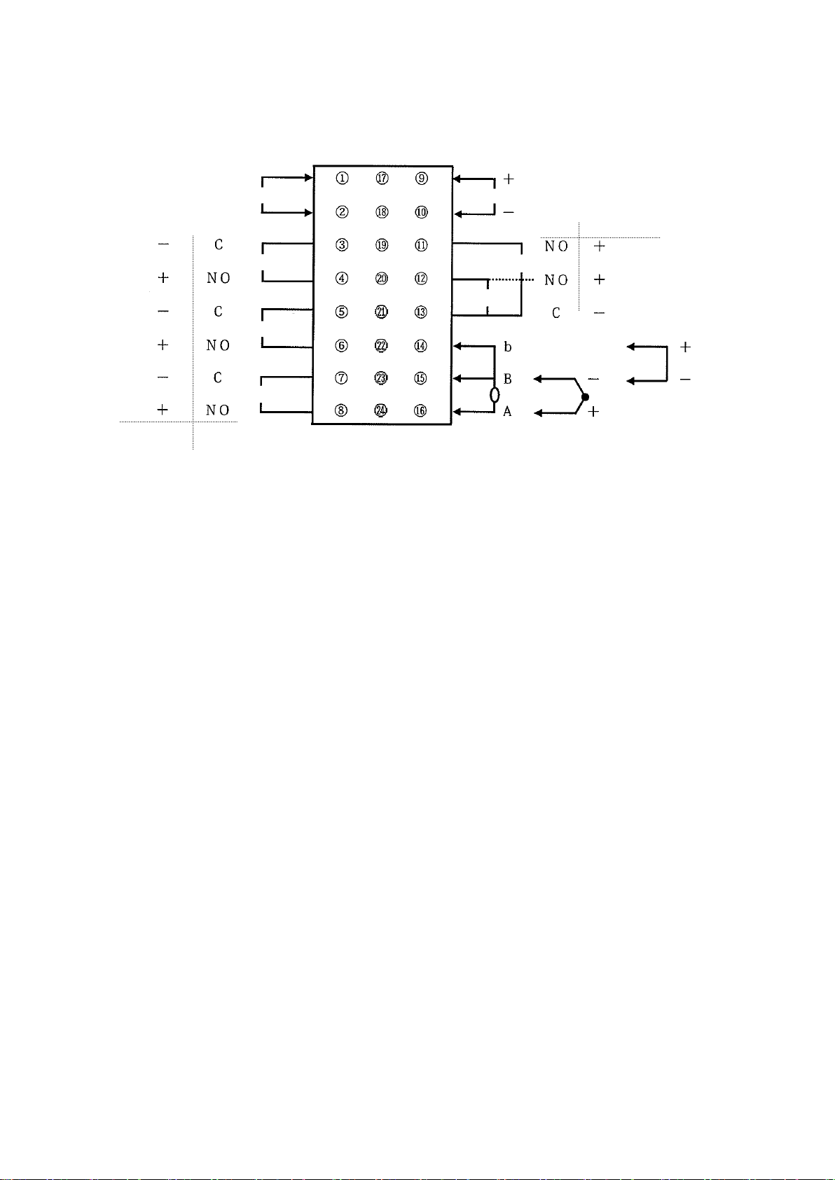
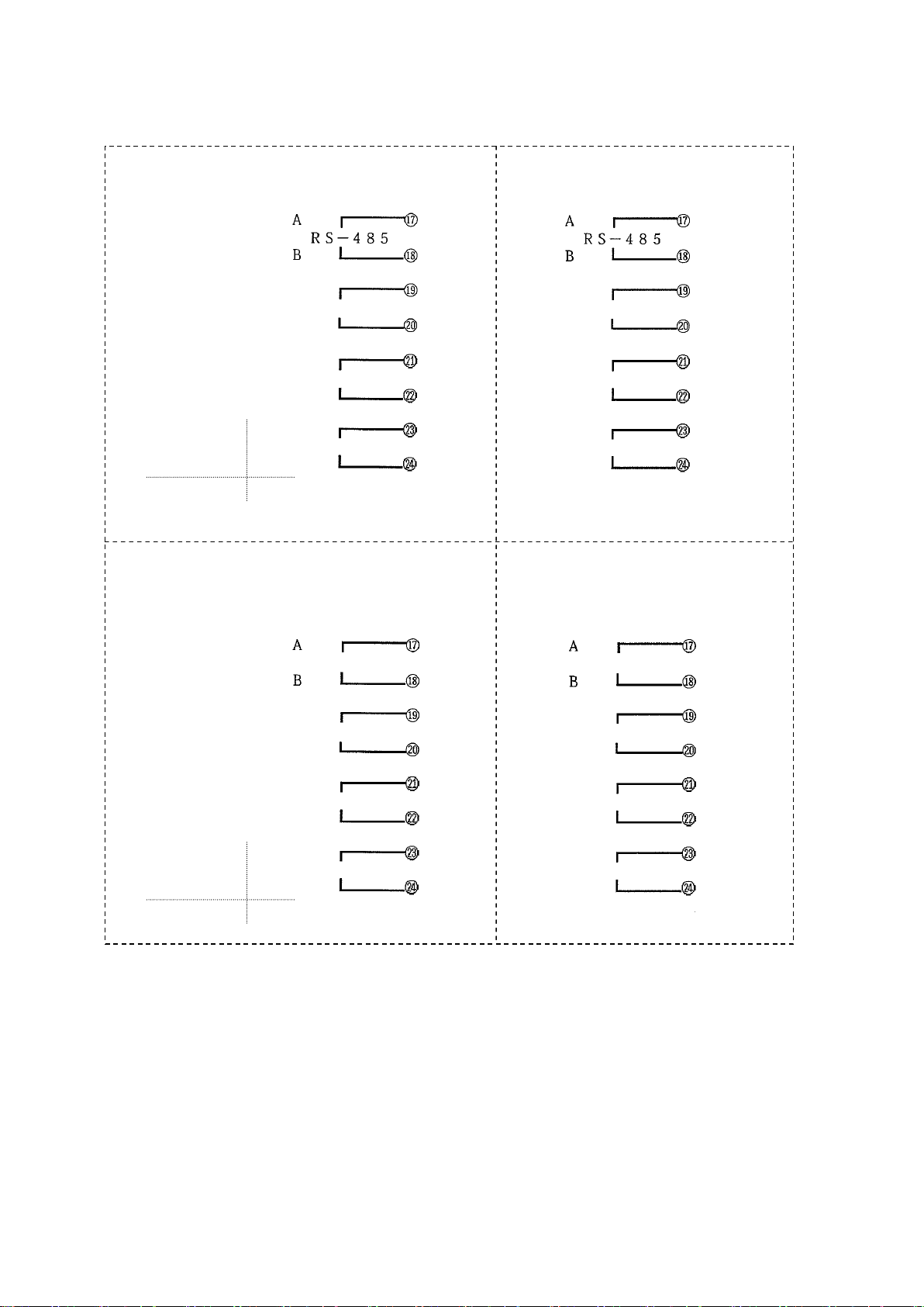
3.2 Terminal arrangement
* Outputs 3 and 4 are for common (C) shared
Relay Open collector
① ⑬ ⑦ NO +
Input power supply
② ⑭ ⑧
NO
+
Output 4
- C ③ ⑮ ⑨ C -
Output 1
+ NO ④ ⑯ ⑩ b +
- C ⑤ ⑰ ⑪ B - -
Output 2
+ NO ⑥ ⑱ ⑫ A +
Relay RTD input TC input Analog input
0 - 10 mV input
Output 3
Other than
relay output
A ⑬ A ⑬ A ⑬
RS-485 RS-485 RS-485
B ⑭ B ⑭ B ⑭
⑮ ⑮ ⑮
CT 1 input DI 1 input CT 1 input
⑯ ⑯ ⑯
⑰ ⑰ ⑰
CT 2 input DI 2 input DI 2 input
⑱ ⑱ ⑱
* Only the above can be selected
for the model with CT and DI.
Specifications for communication
and 2 points of CT
Specifications for communication
and 2 points of DI
Specifications for communication,
1 point of CT and 1 point of DI
Main body rear surface terminals
+ + + - -
-
Notation for terminal arrangement is as follows.
C: Common
NO: Normal open
+, -: There is polarity for wiring.
A, B, b: There is designation for wiring.
CT: Current transformer input (no polarity)
DI: Digital input
RTD: Resistance temperature detector input
TC: Thermocouple input
I: Current input
V: Voltage input (excluding 0 - 10 mV)
* Parameters can be used for changing input types. (Multi-input)
* “NO” and “C” for outputs are for the equipment model with relay contact output. “+” and “-” for
other than the equipment model with relay contact output.
* Terminal block is not provided in case the model selection is not made at the product model.
★ TTM-204
48-7009-E 3-3
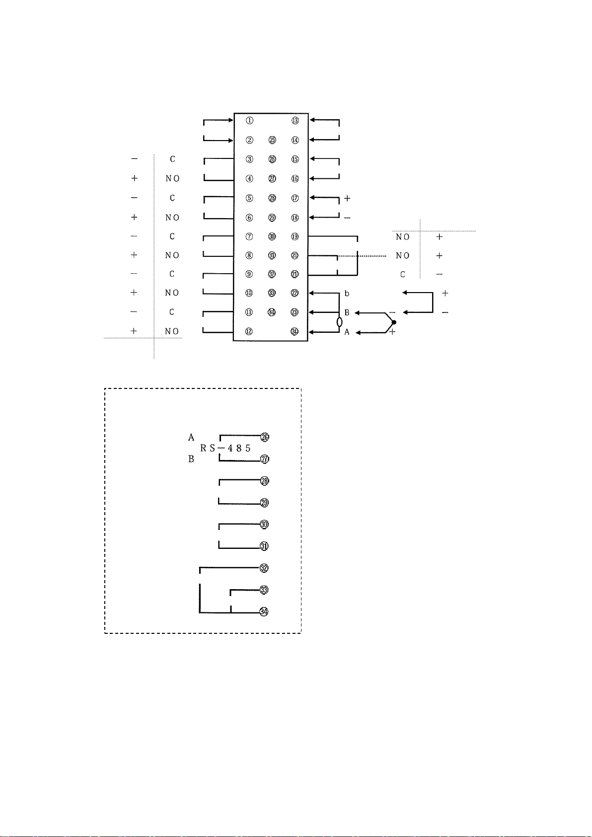
Page 26
★ TTM-207
Input power supply
Output 1
Output 2
Output 5
Other than
relay output
Relay
(The output 5 is only for an open collector.)
AI input (models in voltage and current)
Output 3
Output 4
Relay
Open collector
* Outputs 3 and 4
are for common
(C) shared
RTD input
TC input
0 - 10 mV input
Analog input
Main body rear surface terminals
48-7009-E 3-4
Page 27
CT 1 input
CT 2 input
Output 7
Open collector
Relay
NO
DI 1 input
DI 2 input
DI 3 input
CT 1 input
DI 2 input
Output 7
Open collector
Relay
NO
CT 1 input
DI 2 input
DI 3 input
RS-485
RS-485
+ + + + + + - - - - -
-
+
-
NO
C
+
-
NO
C
Communication + 2 points of CT + Output 7 Communication + 3 points of DI
Communication + 1 point of CT + 1 point of Communication + 1 point of CT +
DI + Output 7 2 points of DI
48-7009-E 3-5
Page 28
★ TTM-205/209
Other than
relay output
Relay
Input power supply
Output 1
Output 2
Output 5
Output 6
Output 7
AI input (models in voltage and current)
Relay
Open collector
* Outputs 3 and 4 are for common (C) shared
Output 3
Output 4
RTD input
TC input
0 - 10 mV input
Analog input
CT 2 input
CT 1 input
DI 1 input
DI 2 input
DI 3 input
DI 4 input
Main body rear surface terminals
+ + +
+ - -
-
Communication + DI
48-7009-E 3-6
Page 29
3.3 Wiring to each terminal
TTM-204
Terminal Nos. ① and ②
TTM-205
TTM-207
TTM-209
Type of power supply
Fluctuation range
Frequency
Power consumption
100 to 240 VAC
85 to 264 VAC
50/60 Hz
10 VA or less
24 VAC
21.6 to 26.4 VAC
50/60 Hz
4 W or less
24 VDC
21.6 to 26.4 VDC
4 W or less
Type of power supply
Fluctuation range
Frequency
Power consumption
100 to 240 VAC
85 to 264 VAC
50/60 Hz
11 VA or less
24 VAC
21.6 to 26.4 VAC
50/60 Hz
6 W or less
24 VDC
21.6 to 26.4 VDC
6 W or less
* Isolation diagram
Where relays and open collectors are included in
outputs
Where outputs are SSRs, current outputs or voltage
outputs
Power supply circuit
Power supply circuit
PV input
CPU circuit
Output 1
PV input
CPU circuit
Output 1
AI input
Output 2
AI input
Output 2
CT input
Outputs 3 to 7
CT input
Outputs 3 to 7
DI
Communication
DI
Communication
In connection diagrams, left side of the terminal number represents inside the equipment while right side
shows the external side of the equipment.
★ Power supply
TTM-204
TTM-205/207/209
* Wire the power supply for instruments in such a way that they don’t receive noise from the power supply of the
power devices.
The use of a noise filter is recommended in case that the equipment is vulnerable to noises.
Take care the following when a noise filter is used.
◎ Install the noise filter as close to a temperature controller as possible.
Wire the instruments in as short a distance as possible to output lines (secondary side) of the noise filter and
power terminals for the temperature controller.
◎ Isolate the noise filter input line (primary side) from its output line (secondary side).
High-frequency elements of noises may be induced, resulting in no provision of much noise attenuation effect as
expected, in case of input and output wires being close one another, such as being bundled together or installed in
a same duct or tube.
◎ Wire the grounding wire of the noise filter in as short a distance as possible.
A long grounding wire is equivalent to insert of an inductance, resulting in deteriorated high-frequency
characteristics.
◎ Before installing the noise filter, peel off the paint applied on a mounting plate of the noise filter as appropriate, in
* For the power supply, use and twist wires that has lesser voltage drop.
* It takes about 4 seconds for the unit to activate after its power is turned on. Use delay relays when
* In case of using the equipment with a 24 V power supply, supply the power from a SELV circuit
* The equipment is not supplied with power supply switch fuses. Separately install fuses in proximity
* The input power supply and the input/output are isolated one anther on the equipment.
order to reduce the contact resistance between the noise filter and equipment housing.
using the equipment for generating signals for interlocking circuits.
(power supply secured with safety).
of the equipment, as needed.
◎ Recommended fuse rating: Rated voltage of 250 V and rated current of 1A
* No. of outputs depends on specifications and models. Isolated
* Outputs 3 to 7 are isolated. ------ Non-isolated
48-7009-E 3-7
Page 30
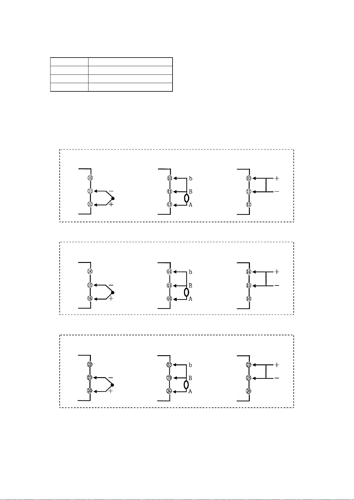
★ Input
TTM-204
Terminal Nos. ⑩, ⑪ and ⑫
* Use sensors that match the types of inputs.
(“K thermocouple” is set as factory default.)
* For thermocouple input, use wires or compensated
leads.
* For input from resistance temperature detector, use
wires that the wire resistance of leads is small and no
resistance difference is present among 3 wires (3-wire
type).
* Provide input signal lines distant from power supply
lines, power lines or load lines so as not to affect input
signal lines with noise induction.
TTM-205
Terminal Nos. ○22, ○23 and ○24
TTM-207
Terminal Nos. ⑭, ⑮ and ⑯
TTM-209
Terminal Nos. ○22, ○23 and ○24
Thermocouple 0 - 10 mV
Resistance temperature
detector
Analog input
TTM-204
Thermocouple 0 - 10 mV
Resistance temperature
detector
Analog input
TTM-205/209
Thermocouple 0 - 10 mV
Resistance temperature
detector
Analog input
TTM-207
48-7009-E 3-8
Page 31

★ AI input (current and voltage only)
TTM-205
Terminal Nos. ⑰ and ⑱
TTM-207
Terminal Nos. ⑨ and ⑩
TTM-209
Terminal Nos. ⑰ and ⑱
TTM-204
Terminal Nos. ⑮, ⑯, ⑰ and ⑱
TTM-205
Terminal Nos. ⑬, ⑭, ⑮ and ⑯
TTM-207
Terminal Nos. ⑲, ⑳, ○21 and ○22
TTM-209
Terminal Nos. ⑬, ⑭, ⑮ and ⑯
* When the event input (DI 1 or
DI 2) is selected, CT 1 or CT 2
are not selectable.
* When the event input (DI 2) is
selected, CT 2 is not selectable.
* When the event input (DI 1 or
DI 2) is selected, CT 1 or CT 2
are not selectable.
* When the event input (DI 2) is
selected, CT 2 is not selectable.
TTM-204
TTM-207
TTM-205/209
TTM-207 TTM-205/209
* AI input is optional.
(TTM-204 is not equipped with AI input.)
* Provide input signal lines distant from power supply lines, power lines or load lines so as not to affect
input signal lines with noise induction.
★ CT (current detector) input
* CT input is optional.
* Heater disconnection failure is detected by CT (current detector) when the heater disconnection alarm
is effective.
* CT possible to be used is “CTL-6-P-N”
* Max. 2 points are selectable (to be designated at order placement).
* CT input is not selectable for analog output.
48-7009-E 3-9
Page 32

★ Event (DI) input
TTM-204
Terminal Nos. ⑮, ⑯, ⑰ and ⑱
TTM-205
Terminal Nos. ○28, ○29, ○30, ○31, ○32, ○33 and ○34
TTM-207
Terminal Nos. ⑲, ⑳, ○21, ○22, ○23 and ○24
TTM-209
Terminal Nos. ○28, ○29, ○30, ○31, ○32, ○33 and ○34
* When CT 1 or CT 2 is
selected, DI 1 or DI 2 are not
selectable.
* When CT 1 is selected, DT 1
is not selectable.
* When CT 1 or CT 2 is
selected, DI 1 or DI 2 is not
selectable.
* When CT 1 is selected, DI 1 is
not selectable.
* When the output 7 is selected,
DI 3 is not selectable.
TTM-204
TTM-207
TTM-205/209
* For TTM-205/209, the common for
DI 3/DI 4 is shared.
Close
Active
Bank switchover
Bank switchover
During constant value run
MD
READY
During program run
Start
Stop
MD
MANUAL
Reverse operation
Forward operation
AT stop
AT start
Timer Stop
Timer Stop
Constant value run
Program run
Step feed (during program run) *1
Pause (during program run) *1
Interlock *1
- - - - - - - - + + + + +
+ + +
+
* DI input is optional.
* Max. 4 points are selectable (to be designated at order placement).
* The following functions can be executed through the DI (digital) inputs.
The DI inputs are external no-voltage contact signals.
* List of functions due to DI
48-7009-E 3-10
*1: Selectable only for a program run.
Close: Contact signal OFF
Active: Contact signal ON
Page 33

★ Communication function
TTM-204
Terminal Nos. ⑬ and ⑭
TTM-205
Terminal Nos. ○26 and ○27
TTM-207
Terminal Nos. ⑰ and ⑱
TTM-209
Terminal Nos. ○26 and ○27
Communication
TTM-204
TTM-207
TTM-205/209
Communication
Communication
* There are two types of communication functions, the “communication” and “loader communication”.
The “Communication” is optional.
★ Communication
* This function is for communication with a host computer. (The communication function option is
required.)
* Communication protocol
TOHO protocol
MODBUS protocol (RTU mode)
MODBUS protocol (ASCII mode)
* Interface
RS485
★ Loader communication
* This communication function is for setting all data of TTM-200 series in a lump.
* In order to use the loader communication, the dedicated software for the communication must be
installed on the personal computer (PC) being used.
* To connect TTM-200 series to your PC, TOHO’s dedicated connection cable “TTM-LOADER” (sold
separately) is required.
48-7009-E 3-11
Page 34

★ Output
Model
Terminal No.
Output 1
Output 2
Output 3
Output 4
Output 5
Output 6
Output 7
TTM-204
③ and ④
⑤ and ⑥
⑦ and ⑨
⑧ and ⑨
TTM-205
③ and ④
⑤ and ⑥
⑲ and ○21
⑳ and ○21
⑦ and ⑧
⑨ and ⑩
⑪ and ⑫
TTM-207
③ and ④
⑤ and ⑥
⑪ and ⑬
⑫ and ⑬
⑦ and ⑧
○
23
and ○24
TTM-209
③ and ④
⑤ and ⑥
⑲ and ○21
⑳ and ○21
⑦ and ⑧
⑨ and ⑩
⑪ and ⑫
Type of output
Output 1
Output 2
Output 3
Output 4
Output 5
Output 6
Output 7
Primary output
(heating)
Secondary output
(cooling)
Transmission
output
Event output
Timer output
End output
Relay contact
250 VAC, 3 A (resistance loads) and 1a contact
Voltage for SSR drive
0 - 12 VDC (load resistance: 600 or greater)
Open collector
24 VDC, 100 mA (load current)
Voltage
0 - 5 VDC, 1 - 5 VDC and 0 - 10 VDC
(resistance loads: 1 k or greater)
0 - 1 VDC and 0 - 10 mVDC (load resistance: 500 k or greater)
Current
4 - 20 mADC (load resistance: 600 or less)
Relay contact
250 VAC, 1 A (resistance loads) and 1a contact
Open collector
24 VDC, 100 mA (load current)
Output 1
Output 2
Outputs 3 and 4
Relay
SSR/current/voltage/
open collector
Relay
SSR/current/voltage/
open collector
* Outputs 3 and 4 are for common shared
Relay
Open collector
Assignment of outputs
: Output assignment possible
: Output assignment not possible
Type of output and specification
* Outputs 1 and 2
* Outputs 3, 4, 5, 6 and 7
TTM-204
48-7009-E 3-12
Page 35

TTM-207
Output 1
Output 2
Outputs 3 and 4
Output 5
Relay
Output 7
SSR/current/voltage/
open collector
Relay
SSR/current/voltage/
open collector
Relay
Open collector
Relay
Open collector
* Outputs 3 and 4 are for common shared
Relay
Open collector
48-7009-E 3-13
Page 36

TTM-205/209
Output 1
Output 2
Outputs 3 and 4
Output 5
Relay
Output 6
SSR/current/voltage/
open collector
Relay
SSR/current/voltage/
open collector
Relay
Open collector
Relay
Open collector
* Outputs 3 and 4 are for common shared
Relay
Open collector
Output 7
Relay
Open collector
○
19
○
20
○
21
* Max. 7 points of outputs are provided. They are usable for control output, event output, RUN/RDY
output, transmission output, and timer outputs (3 points).
They should be designated at order placement. See the model table on page 1-3.
* No. of outputs selectable depends on models. In the table “★ Output” on page 3-12, cells filled
with diagonal lines indicate that none is selectable. Selection can also be checked on the model table
on page 1-3.
* “NO” and “C” for outputs are for the equipment model of relay contact output. “+” and “-” for
outputs are for other than the equipment model of relay contact output. Properly wire outputs to
target connections, as target connections are designated.
(Take sufficient care the polarity “+” and “-” when wiring.)
48-7009-E 3-14
Page 37

3-4 Examples of wiring
Temperature sensor
(K thermocouple)
External
relay
Heater
★ Connection configuration
★ Configuration example
TTM-204
Heater
External
relay
K thermocouple
* Take care when wiring, as thermocouple
has polarity of “+” and “-.”
Power
supply
(Example) TTM-204
Power
supply
Terminal No.
Description
①
Power supply
②
③
Output 1
Common
④
Normal open
⑤
Output 2
Not used in this case.
⑥
⑦
Output 3
Output 4
Not used in this case.
⑧
⑨
⑩
Input
Not used in this case.
⑪
“-” side
⑫
“+” side
⑬
Communication
Not used in this case.
⑭
⑮
CT or DI input
Not used in this case.
⑯ ⑰ ⑱
1) Input: K thermocouple, output 1: relay contact output and single phase 100 V
Terminal description for the above wiring example
48-7009-E 3-15
Page 38

2) Input: resistance temperature detector, output 1: SSR drive voltage and single phase 100 V
★ Configuration example
Temperature sensor
(resistance
temperature detector)
(Example) TTM-209
TTM-209
Heater
★ Connection configuration
Power
supply
Heater
Resistance
temperature
detector
* Take care wiring, as “A,” “B” and “b” are
designated on a resistance temperature detector.
TRS1245
SSR
Power
supply
Terminal
No.
Description
Terminal
No.
Description
①
Power supply
⑲
Output 3
Output 4
Not used in this case.
② ⑳ ③
Output 1
“-” side
○
21
④
“+” side
○
22
Input
b
⑤
Output 2
Not used in this case.
○
23
B ⑥
○
24
A
⑦
Output 5
Not used in this case.
○
25
This terminal is not used.
⑧
○
26
Communication
Not used in this case.
⑨
Output 6
Not used in this case.
○
27
⑩
○
28
DI input
Not used in this case.
⑪
Output 7
Not used in this case.
○
29
⑫
○
30
⑬
CT input
Not used in this case.
○
31
⑭
○
32
⑮
○
33
⑯
○
34
⑰
AI input
Not used in this case.
⑱
Terminal description for the above wiring example
48-7009-E 3-16
Page 39

3) Input: resistance temperature detector, output 1: SSR drive voltage and 3-phase 200 V
Temperature sensor
(resistance temperature
detector)
(Example) TTM-204
* Usable SSR in 3-pahse 200 V is a product
with the input current of 10 mA or less.
Heater
★ Connection configuration
★ Configuration example
Heater
* Take care when wiring,
as SSR has polarity of
“+” and “-.”
* Take care wiring, as “A,” “B”
and “b” are designated on a
resistance temperature detector.
Power
supply
Resistance
temperature
detector
-
SSR
+
-
SSR
+
Power
supply
Terminal No.
Description
①
Power supply
②
③
Output 1
“-” side
④
“+” side
⑤
Output 2
Not used in this case.
⑥
⑦
Output 3
Output 4
Not used in this case.
⑧
⑨
⑩
Input
b
⑪
B
⑫ A ⑬
Communication
Not used in this case.
⑭
⑮
CT or DI input
Not used in this case.
⑯
⑰
⑱
* SSR may be shorted out
due to its internal failure.
The use of “temperature
fuses” or an
“over-temperature
prevention device” is
recommended to cut off the
output circuit of SSR.
Terminal description for the above wiring example
48-7009-E 3-17
Page 40

4) Input: K thermocouple, output 1: SSR drive voltage, output 2: relay contact output and single phase 100
Temperature sensor
(K thermocouple)
★ Configuration example
(Example) TTM-205
External
relay
Refriger-
ator
Heater
Power
supply
★ Connection configuration
* SSR may be shorted out due to its internal failure. The use of temperature
fuses or an over-temperature prevention device is recommended to cut off
the output circuit of SSR.
K
thermocouple
* Take care when wiring,
as thermocouple has
polarity of “+” and “-.”
Refriger-
ator
External
relay
Heater
TRS1245
Power
supply
Terminal
No.
Description
Terminal
No.
Description
①
Power supply
⑲
Output 3
Output 4
Not used in this case.
②
⑳
③
Output 1
“-” side
○
21
④ “+” side
○
22
Input
Not used in this case.
⑤
Output 2
Common
○
23
“-” side
⑥
Normal open
○
24
“+” side
⑦
Output 5
Not used in this case.
○
25
This terminal is not used.
⑧
○
26
Communication
Not used in this case.
⑨
Output 6
Not used in this case.
○
27
⑩
○
28
DI input
Not used in this case.
⑪
Output 7
Not used in this case.
○
29
⑫
○
30
⑬
CT input
Not used in this case.
○
31
⑭
○
32
⑮
○
33
⑯
○
34
⑰
AI input
Not used in this case.
⑱
V (heating/cooling control)
Terminal description for the above wiring example
48-7009-E 3-18
Page 41

5) Input: K thermocouple, output 1: relay contact output, output 2: transmission output and single phase
★ Configuration example
(Example) TTM-204
TTM-204
Temperature sensor
(K thermocouple)
External
relay
Heater
Recorder
★ Connection configuration
External
relay
Heater
K
thermocouple
* Take care when wiring, as
thermocouple has polarity of “+”
and “-.”
Power
supply
Power
supply
Terminal No.
Description
①
Power supply
②
③
Output 1
Common
④
Normal open
⑤
Output 2
“-” side
⑥
“+” side
⑦
Output 3
Output 4
Not used in this case.
⑧ ⑨ ⑩
Input
Not used in this case.
⑪
“-” side
⑫
“+” side
⑬
Communication
Not used in this case.
⑭
⑮
CT or DI input
Not used in this case.
⑯
⑰
⑱
100 V
Terminal description for the above wiring example
48-7009-E 3-19
Page 42

4. Basic operation
Basic operation is described in this chapter.
4.1 Flow of setting mode .............................................................................................................................. 4-2
4.2 Basic operation ....................................................................................................................................... 4-4
4.2.1 Switchover of parameters (flow as a whole) .................................................................................. 4-4
4.2.2 Description of setting item selection screen ................................................................................. 4-19
4.2.3 Setting of input types ................................................................................................................... 4-20
4.2.4 Setting of key functions ............................................................................................................... 4-21
4.2.5 How to set the SV limiter setting ................................................................................................. 4-22
4.2.6 How to set control types ............................................................................................................... 4-23
4.2.7 How to set outputs ........................................................................................................................ 4-25
4.2.8 How to set priority screens ........................................................................................................... 4-26
4.2.9 Switchover to the blind setting mode ........................................................................................... 4-27
4.2.10 Switchover to the ON/OFF control .............................................................................................. 4-29
48-7009-E 4-1
Page 43

4.1 Flow of setting mode
PROG
25
0
25
0
INP1
The equipment does not operate for
about 4 seconds after power-on.
At SET 21 program mode setting
In (C/P = 0) constant value run mode
Power-on
Initial screen
Constant value run mode screen
4 seconds
4 seconds
At SET 21 program mode setting
In (C/P 0) program run mode
Program run mode screen
The following is possible in this mode: display of PV value
(present value), setting of SV value (setting value) which is
the target value of control, display of remaining time
monitor for timer 1, 2 and 3, display of priority screens 1 to
16, display of the bank No. that is presently set and various
functions in effect (output, CT, communication, DI, AI, etc.)
The following is possible in this mode: display of PV
value (present value), program run status for SV value,
display of remaining time monitor for timer 1, 2 and 3,
display of priority screens 1 to 16, display of the bank
No. that is presently set and various functions in effect
(output, CT, communication, DI, AI, etc.)
MODE key for
2 seconds
At SET 21 program mode setting
Transition is made one another
according to the C/P setting.
MODE key for
2 seconds
Setting item selection screen (SET 01 - SET 23) (See the page 6-1 and thereafter.)
Various parameters regarding SET 01 - SET 23 are set.
SET 21 and 22 are settings for the program run.
MODE key
Parameter setting screen in each SET
Various parameters are set. (See pages 6-2 to 6-xx.)
* Using the MODE key, parameter screens for each setting mode is displayed in sequence, and the screen
returns to the SET** screen.
* Using the ▲ /▼ key, the setting item selection screens SET 01 to SET 23 is displayed in sequence.
(In case of no function registered, the corresponding screen is not displayed.)
(For program run mode, see pages 6-13 to 6-xx.)
* The screen moves back to the operating mode screen when holding the MODE key pressed for 2 seconds in
parameter screens for each SET screen.
Blind setting screen
The screen for setting items to be “blinded”
(non-displayed) by using parameters appears.
For details, see pages 4-27 and 28.
MODE key for
10 seconds
MODE key for
10 seconds
★ No key operation for about 2 minutes automatically moves the screen back to the operating mode screen.
★ If a function is not specified, corresponding SET screen is not displayed.
★ Holding the MODE key pressed for at least 2 seconds moves the setting item selection screen back to the
operating mode screen or vice versa.
★ Use the ▲/▼ key to move the parameter setting screens.
★ Use the MODE key to move each parameter setting screen.
48-7009-E 4-2
Page 44

■ Initial screen
Initial screen
Parameter for input display
Input type No.
(“0” is set at factory shipment.)
4 seconds
0
INP1
0
25
Constant value run
PV value (present value)
SV value (target value)
Power-on
Initial screen
Parameter for input display
Input type No.
(“0” is set at factory shipment.)
4 seconds
0
INP1
Program run mode screen
PV value (present value)
SV value (PROG)
Power-on
PROG
25
Input type No. and input type
No.
Input type
0
K thermocouple
1
J thermocouple
2
T thermocouple
3
E thermocouple
4
R thermocouple
5
S thermocouple
6
B thermocouple
7
N thermocouple
8
U thermocouple
9
L thermocouple
10
WRe5-26 thermocouple
11
PR40-20 thermocouple
12
PLII thermocouple
13
Pt100
14
JPt100
15
0 - 10 mVDC
16
0 - 1 VDC
17
0 - 5 VDC
18
1 - 5 VDC
19
0 - 10 VDC
20
4 - 20 mADC
The input type number is displayed right after the power turns on, and in 4 seconds, the run mode screen is
displayed.
At SET 21 program mode setting
A (C/P 0) program run mode is established.
48-7009-E 4-3
Page 45

4.2 Basic operation
* The ▲/▼ key is used for switching over setting item selection screens.
* The MODE key is used for switching over screens in each setting mode.
The screen loops back to the setting item selection screen.
* Some mode screens are not displayed, depending on product specifications.
Operating mode
MODE key held pressed
for 2 seconds
Input 1 setting mode
Key function setting
mode
Control setting mode
OUT 1 setting mode
Bank setting mode
MODE key
S04 -51
MODE key
MODE key
▲key
▼key
Input 2 setting mode
MODE key
MODE key
MODE key
▲key
▼key
▲key
▼key
▲key
▼key
▲key
▼key
▲key
▼key
▲key
▼key
MODE key
MODE key
MODE key
MODE key
MODE key
MODE key
MODE key
MODE key
MODE key
MODE key
MODE key
MODE key
MODE key
Program run function setting
* Setting parameters of SET 21 C/P or after and those of SET 22 are not
displayed if SET 21 C/P 0.
For details, see pages 6-13 and 14.
Bank auto-switchover function setting
* Setting parameters of SET 23 are not displayed if SET 23 bAF 0.
For details, see page 6-15.
Flow of each setting item selection screen and each setting mode is described.
4.2.1 Switchover of parameters (flow as a whole)
* Nos. located in upper left of each parameter screen is identical to the Nos. for items in each parameter screen.
Notation example S20-1: First item in the parameter screen SET 20.
48-7009-E 4-4
Page 46

Flow of each setting mode
Constant value run mode
SET21 program mode setting
A (C/P = 0) constant value run mode is established.
1. PV/SV screen
2. Timer 1 monitor
3. Timer 2 monitor
4. Timer 3 monitor
5. Priority screen 1
(The priority screens
from 1 to 16 displayed
in sequence)
20. Priority screen 16
To item 1
Program run mode
SET21 program mode setting
A (C/P = 1) program run mode is established.
To item 1
MODE key
MODE key
MODE key
MODE key
MODE key
1. Program run screen
2. Step SV value screen
3. Step time monitor
4. Program run start/stop screen
5. Timer 1 monitor
6. Timer 2 monitor
7. Timer 3 monitor
8. Priority screen 1
(The priority screens from 1
to16 displayed in sequence)
23. Priority screen 16
MODE key
MODE key
MODE key
MODE key
MODE key
MODE key
MODE key
MODE key
48-7009-E 4-5
Page 47

SET 1: Input 1 setting mode
0. Setting item selection screen
1 Input 1 type setting
2. Scaling upper limit setting
* Displayed with current/voltage
input.
3. Scaling lower limit setting
* Displayed with current/voltage
input.
5. PV compensation gain setting
* Displayed during PV gain zero
point compensation.
4. PV compensation function
setting *1
6. PV compensation zero setting
* Displayed during PV gain zero
point compensation.
7. Lower limit setting before PV
compensation
* Displayed during PV X-Y
2-point compensation
To SET 01, item 9
8. Upper limit setting before PV
compensation
* Displayed during PV X-Y
2-point compensation
9. Lower limit setting after PV
compensation
* Displayed during PV X-Y
2-point compensation
10. Upper limit setting after PV
compensation
* Displayed during PV X-Y
2-point compensation
11. Input filter setting
12. Decimal point setting
To SET 01, item 0
*1: PV compensation function setting
When (PVF1 0) is selected, select PV gain zero point compensation.
When (PVF1 1) is selected, select PV X-Y 2-point compensation.
For details, see pages 6-4 to 6-6.
MODE key
MODE key
MODE key
MODE key
MODE key
MODE key
MODE key
MODE key
MODE key
MODE key
MODE key
MODE key
48-7009-E 4-6
Page 48

SET 2: Input 2 setting mode
1. Input 2 type setting
2. Scaling upper limit setting
* Displayed with
current/voltage input.
3. Scaling lower limit setting
* Displayed with
current/voltage input.
5. PV compensation
zero setting
4. PV compensation gain
setting
6. Input filter setting
7. Local/remote switchover
To SET 02, item 0
0. Setting item
selection screen
SET 3: Key function setting mode
0. Setting item
selection screen
1. Function key 1
function setting
2. Function key 2
function setting
3. Function key 3
function setting
4. Function key 4
function setting
5. Function key 5
function setting
6. Key lock setting mode
To SET 03, item 0
48-7009-E 4-7
Page 49

SET 4: Control setting mode
0. Setting item selection
screen
1. Bank setting
3. Control setting
4. SV limiter upper limit
setting
5. SV limiter lower limit
setting
6. Control mode setting
7. Control type setting
8. PID control type
setting
9. Type B mode setting
10. Forward/reverse
operation setting
To S04-11
To S04-21
11. Primary control
operating amount
12. Primary control
output gain setting
13. Tuning type setting
14. AT coefficient setting
15. AT sensitivity setting
16. AT start screen
17. Proportional band
setting
18. Integral time setting
19. Derivative time setting
20. Primary control proportional
cycle
Initial value Relay: 20 seconds
SSR: 2 seconds
Continued to the next page
2. Bank upper limit
setting
MODE key
MODE key
MODE key
MODE key
MODE key
MODE key
MODE key
MODE key
MODE key
MODE key
MODE key
MODE key
MODE key
MODE key
MODE key
MODE key
MODE key
MODE key
MODE key
MODE key
MODE key
48-7009-E 4-8
Page 50

21. Anti-reset windup
22. Setting of primary
control operation
amount limiter upper
23. Setting of primary
control operation amount
limiter lower limit
24. Setting of primary control
operation amount change
rate limiter ascending
25. Setting of primary control
operation amount change
rate limiter descending
26. Setting of primary
controller soft start
output
27. Setting of primary
controller soft start
time
28. Setting of primary
control operation
amount at fault
29. Setting of primary
control loop anomaly
PV threshold
31. Setting of primary
control loop anomaly PV
threshold
30. Setting of primary
control operation amount
at fault and control
amount threshold
32. Setting of primary
control loop fault time
33. Setting of primary
control OFF point
position selection
34. Setting of primary control
sensitivity
35. Setting of primary control
OFF point position
36. Primary control safeguard
off timer
(0 to 99 minutes)
37. Primary control
safeguard on timer
(0 to 99 minutes)
38. Secondary control
operation amount
39. Setting of secondary
control output gain
40. Setting of secondary
control proportional band
(0.10 to 10.00 times)
41. Setting of secondary control
proportional interval
To S04-32
MODE key
To S04-42
MODE key
MODE key
MODE key
MODE key
MODE key
MODE key
MODE key
MODE key
MODE key
MODE key
MODE key
MODE key
MODE key
MODE key
MODE key
MODE key
MODE key
MODE key
MODE key
MODE key
Continued to the next page
48-7009-E 4-9
Page 51

42. Setting of secondary
control operation amount
limiter upper limit
To S04-52
MODE key
43. Setting of secondary
control operation amount
limiter lower limit
44. Setting of secondary
control operation amount
change rate limiter
ascending
45. Setting of secondary
control operation amount
change rate limiter
descending
46. Setting of secondary
control operation amount
at fault
47. Setting of secondary
control loop anomaly PV
threshold
48. Setting of secondary
control loop anomaly MV
threshold
49. Setting of secondary
control loop anomaly PV
change threshold
50. Setting of secondary
control loop fault time
51. Setting of secondary
control sensitivity
52. Setting of secondary
control OFF point
position
53. Secondary control
safeguard off timer
(0 to 99 minutes)
54. Secondary control
safeguard on timer
(0 to 99 minutes)
55. Setting of manual reset
56. Setting of dead band
57. Setting of Ramp time
58. Setting of valve motor
stroke time
59. Setting of valve motor
drive dead band
60. Initial open ratio after AT
completion
To SET 04, item 0
MODE key
MODE key
MODE key
MODE key
MODE key
MODE key
MODE key
MODE key
MODE key
MODE key
MODE key
MODE key
MODE key
MODE key
MODE key
MODE key
MODE key
MODE key
48-7009-E 4-10
Page 52

SET 5: OUT 1 setting mode
0. Setting item selection
screen
1. Target connection
setting
2. Event function 1
setting
3. Event upper limit
setting
4. Event lower limit
setting
5. Event sensitivity setting
6. Event delay timer
setting
7. Event function 2 setting
(PV abnormality)
8. Event function 3 setting
(CT abnormality)
9. Event function 4 setting
(Loop abnormality)
To S05-10
To SET 05, item 0
10. Event polarity setting
11. Transmission output
function setting
12. Transmission scaling
upper limit setting
13. Transmission scaling
lower limit setting
MODE Key
48-7009-E 4-11
Page 53

SET 6: OUT 2 setting mode
0. Setting item selection
screen
1. Target connection
setting
2. Event function 1
setting
3. Event upper limit
setting
4. Event lower limit
setting
5. Event sensitivity setting
6. Event delay timer
setting
7. Event function 2 setting
(PV abnormality)
8. Event function 3 setting
(CT abnormality)
9. Event function 4 setting
(Loop abnormality)
To S06-10
To SET 06, item 0
10. Event polarity setting
11. Transmission output
function setting
12. Transmission scaling
upper limit setting
13. Transmission scaling
lower limit setting
48-7009-E 4-12
Page 54

0. Setting item selection
screen
1. Target connection
setting
2. Event function 1
setting
3. Event upper limit
setting
4. Event lower limit
setting
5. Event sensitivity setting
6. Event delay timer
setting
7. Event function 2 setting
(PV abnormality)
8. Event function 3 setting
(CT abnormality)
9. Event function 4 setting
(Loop abnormality)
To SET 07, item 0
10. Event polarity setting
SET 7: OUT 3 setting mode
0. Setting item selection
screen
1. Target connection
setting
2. Event function 1
setting
3. Event upper limit
setting
4. Event lower limit
setting
5. Event sensitivity setting
6. Event delay timer
setting
7. Event function 2 setting
(PV abnormality)
8. Event function 3 setting
(CT abnormality)
9. Event function 4 setting
(Loop abnormality)
To SET 08, item 0
10. Event polarity setting
SET 8: OUT 4 setting mode
48-7009-E 4-13
Page 55

0. Setting item selection
screen
1. Target connection
setting
2. Event function 1
setting
3. Event upper limit
setting
4. Event lower limit
setting
5. Event sensitivity setting
6. Event delay timer
setting
7. Event function 2 setting
(PV abnormality)
8. Event function 3 setting
(CT abnormality)
9. Event function 4 setting
(Loop abnormality)
To SET 09, item 0
10. Event polarity setting
SET 9: OUT 5 setting mode
0. Setting item selection
screen
1. Target connection
setting
2. Event function 1
setting
3. Event upper limit
setting
4. Event lower limit
setting
5. Event sensitivity setting
6. Event delay timer
setting
7. Event function 2 setting
(PV abnormality)
8. Event function 3 setting
(CT abnormality)
9. Event function 4 setting
(Loop abnormality)
To SET 10, item 0
10. Event polarity setting
SET 10: OUT 6 setting mode
48-7009-E 4-14
Page 56

0. Setting item selection
screen
1. Target connection
setting
2. Event function 1
setting
3. Event upper limit
setting
4. Event lower limit
setting
5. Event sensitivity setting
6. Event delay timer
setting
7. Event function 2 setting
(PV abnormality)
8. Event function 3 setting
(CT abnormality)
9. Event function 4 setting
(Loop abnormality)
To SET 11, item 0
10. Event polarity setting
SET 11: OUT 7 setting mode
SET 12: CT setting mode
0. Setting item selection
screen
1. CT 1 target connection
setting
2. CT 1 current value
monitor
3. CT 1 abnormal current
value setting
4. CT 2 target connection
setting
5. CT 2 current value
monitor
6. CT 2 abnormal current
value setting
0. Setting item selection
screen
1. Function setting
2. Polarity setting
SET 13: DI setting mode
To SET 13, item 0
To SET 12, item 0
48-7009-E 4-15
Page 57

SET 14: Timer 1 setting mode
0. Setting item selection
screen
1. Function setting
2. Unit setting
3. SV permissible range
setting
4. ON delay timer
setting
5. OFF delay timer
setting
6. Repeat count
setting
7. Remaining time
monitor
To SET 14, item 0
To SET 15, item 0
SET 15: Timer 2 setting mode
0. Setting item selection
screen
1. Function setting
2. Unit setting
3. SV permissible range
setting
4. ON delay timer
setting
5. OFF delay timer
setting
6. Repeat count
setting
7. Remaining time
monitor
48-7009-E 4-16
Page 58

SET 16: Timer 3 setting mode
0. Setting item selection
screen
1. Function setting
2. Unit setting
3. SV permissible range
setting
4. ON delay timer
setting
5. OFF delay timer
setting
6. Repeat count
setting
7. Remaining time
monitor
To SET 16, item 0
To SET 17, item 0
SET 17: Communication setting mode
0. Setting item selection
screen
1. Communication
protocol setting
2. Communication
parameter setting
3. Communication speed
setting
4. Communication
address setting
5. Response delay time
setting
6. Communication
switchover setting
48-7009-E 4-17
Page 59

SET 18: Initial setting mode
0. Setting item selection
screen
1. Password cancel
2. PV normal display color
3. PV color auto-display low
(0: green, 1: red, 2: orange)
4. PV color auto-display middle
(0: green, 1: red, 2: orange)
5. PV color auto-display high
(0: green, 1: red, 2: orange)
6. Switchover width for
PV display color
7. PV event at-output
display color
8. PV at-abnormality
display color
9. CT at-abnormality
display color
10. Loop at-abnormality
display color
To S18-11
11. Blind temporary call
setting
12. Setting value backup
14. Password setting
13. Initialization of setting
value
To SET 18, item 0
SET 19: Priority screen setting mode
0. Setting item selection
screen
1. Priority screen 1 setting
To SET 19, item 0
* Priority screens 1 - 16
displayed in sequence
SET 20: Bank setting mode
0. Setting item selection
screen
1. Bank selection 1 setting
16. Bank selection 16 setting
* Bank selections 1 - 16
displayed in sequence
To SET 20, item 0
16. Priority screen 16
setting
48-7009-E 4-18
Page 60

4.2.2 Description of setting item selection screen
Setting item
selection screen
Description
SET 01
Mode regarding input 1 setting
P6-2 to 7
SET 02
Mode regarding input 2 setting
P6-8 to 11
SET 03
Mode regarding key function setting
P6-12 and 13
SET 04
Mode regarding control content setting
P6-14 to 48
SET 05
Mode regarding output (OUT) 1 setting
P6-49 to 56
SET 06
Mode regarding output (OUT) 2 setting
SET 07
Mode regarding output (OUT) 3 setting
SET 08
Mode regarding output (OUT) 4 setting
SET 09
Mode regarding output (OUT) 5 setting
SET 10
Mode regarding output (OUT) 6 setting
SET 11
Mode regarding output (OUT) 7 setting
SET 12
Mode regarding CT setting
P6-57 and 58
SET 13
Mode regarding DI setting
P6-59 to 61
SET 14
Mode regarding timer 1 setting
P6-62 to 64
SET 15
Mode regarding timer 2 setting
SET 16
Mode regarding timer 3 setting
SET 17
Mode regarding communication setting
P6-65 and 66
SET 18
Mode regarding initial setting
P6-67 to 70
SET 19
Mode regarding priority screen setting
P6-71
SET 20
Mode regarding bank setting
P6-72
SET 21
Mode regarding program function setting
P6-73 to 76
SET 22
Mode regarding program setting
P6-77 to 79
SET 23
Mode regarding bank auto-switchover
P6-80 to 83
* For details of setting value content, see above-mentioned parameter settings (P6-2 to 83).
* For details of SET 21 to 23 setting modes, see P5-47 to 75.
* For setting screens for SET 21 to 23, see P5-52 (SET 21), P5-55 (SET 22) and P5-72 (SET 23).
48-7009-E 4-19
Page 61

4.2.3 Setting of input types
Power-on
Initial screen
Parameter for input display
Input type No.
(“0” is set at factory shipment.)
SET 21 program mode setting
A (C/P 0) constant value run mode
is established.
SET 21 program mode setting
A (C/P 0) program run mode is established.
4 seconds
Constant value run mode screen
Hold MODE key pressed for 2 seconds
PV value (present value)
SV value (target value)
Hold MODE key pressed for 2 seconds
Input 1 setting mode
Each set screen
Each setting mode
Press MODE key.
S01-1 Input type setting screen
Input type No.
For program run mode screen:
PV value (present value)
SV value (PRoG)
Hold MODE key pressed for 2 seconds
Setting mode is the same as that for
constant value run mode.
(To input 1 setting screen)
Input type No. and input type
No.
Input type
0
K thermocouple
1
J thermocouple
2
T thermocouple
3
E thermocouple
4
R thermocouple
5
S thermocouple
6
B thermocouple
7
N thermocouple
8
U thermocouple
9
L thermocouple
10
WRe5-26 thermocouple
11
PR40-20 thermocouple
12
PLII thermocouple
13
Pt100
14
JPt100
15
0 - 10 mVDC
16
0 - 1 VDC
17
0 - 5 VDC
18
1 - 5 VDC
19
0 - 10 VDC
20
4 - 20 mADC
Settings for matching the input types being used is done.
* The factory default is set at “0: K thermocouple”.
* Input types are set in this screen.
Numbers for input types are identical to those located in upper
right of the input type number table.
In addition, what each number means is coincident with what
is described in the input type number table.
* Use the ▲/▼ key for setting the numbers.
The following is displayed when “0: K thermocouple,” which
is set at factory shipment, is changed to “1: J thermocouple.”
* Holding the MODE key pressed for 2 seconds moves each setting screen to the operating mode screen.
* In about 2 minutes, each setting screen (or any setting screen) automatically moves back to the operating mode screen.
48-7009-E 4-20
Page 62

4.2.4 Setting of key functions
Constant value run mode screen
PV value (present value)
SV value (target value)
Hold MODE key pressed for 2 seconds.
Input 1 setting screen
Hold MODE key pressed for 2 seconds.
Each set screen
Each setting mode
Press the ▲ key twice.
Press it, however, once for TTM-204.
Key function setting screen
Press MODE key.
S03-1 Function key 1 function setting screen
* The function key functions are set in this screen.
For content of key functions, see the function key function assignment table as shown below.
* The number displayed in the screen is coincident with that listed in the assignment table.
* Use the ▲/▼ key for setting the numbers.
* At factory shipment, “00: no function” is set.
* Use the MODE key to move the screen for the setting screen to set the function keys 2 to 5.
The screens change in sequence each time when the MODE key is pressed.
(Note that only the function key 1 is available for TTM-204.)
Each set screen
Each setting mode
No.
Pressing time setting
No.
Function setting
★☆
★☆
0*
N/A
*0
No function
1*
Pressing time of 1 second
*1
Digit shift
2*
Pressing time of 2 seconds
*2
Control mode/control stop
3*
Pressing time of 3 seconds
*3
AT start/AT stop
4*
Pressing time of 4 seconds
*4
Timer start/reset
5*
Pressing time of 5 seconds
*5
Screen reverse feed
*6
ENT
*7
Bank switchover
*8
AUTO/MANUAL switchover
*9
SV/MV screen switchover
*A
Constant value run/program run switchover
*B
Step feed
*C
Pause
*D
SET 22 call-up function
For program run mode screen:
PV value (present value)
SV value (PRoG)
Hold MODE key pressed for 2 seconds
Setting mode is the same as that for constant
value run mode.
(To input 1 setting screen)
How to set key functions is described.
Function key function assignment table
Example 1: 23 Two-second prolonged pressing makes the key effective, enabling the PID auto-tuning
Example 2: 44 Four-second prolonged pressing makes the key effective, enabling the timer function
* Holding the MODE key pressed for 2 seconds moves each setting screen to the operating mode screen.
* In about 2 minutes, each setting screen (or any setting screen) automatically moves back to the operating
mode screen.
* The function key functions A to D are active only during a program run. They are also settable during a
48-7009-E 4-21
constant value run.
start/stop key setting.
start/reset key setting.
Page 63

4.2.5 How to set the SV limiter setting
Constant value run mode screen
PV value (present value)
SV value (target value)
Hold MODE key pressed for 2 seconds.
Input 1 setting screen
Each set screen
Each setting mode
Press the ▲ key three times.
Press it, however, twice for TTM-204.
Control setting mode
Press MODE key three times.
S04-3 SV limiter upper limit setting screen
* The SV limiter upper limit is set in this screen.
* Use the ▲/▼ key for the setting.
* The set value is a value of MAX (upper limit) for which the SV setting is allowed.
* The value is set at “1200” at factory shipment.
* A small value of SLH contributes to prevent erroneous setting operation, resulting in
prevention of fire or failure.
S04-4 SV limiter lower limit setting screen
* The SV limiter lower limit is set in this screen.
* Use the ▲/▼ key for the setting.
* The set value is a value of MIN (lower limit) for which the SV setting is allowed.
* The value is set at “0” at factory shipment.
* Holding the MODE key pressed for 2 seconds moves each setting screen to the operating mode screen.
* In about 2 minutes, each setting screen (or any setting screen) automatically moves back to the operating
mode screen.
Hold MODE key pressed for 2 seconds.
For program run mode screen:
PV value (present value)
SV value (PRoG)
Hold MODE key pressed for 2 seconds
Setting mode is the same as that for constant
value run mode.
(To input 1 setting screen)
The SV limiter is for setting a settable range with upper and lower limits.
The range is a basis for setting the proportional band for the PID control.
48-7009-E 4-22
Page 64

4.2.6 How to set control types
Constant value run mode screen
PV value (present value)
SV value (target value)
Hold MODE key pressed for 2 seconds.
Input 1 setting screen
Each set screen
Each setting mode
Press the ▲ key three times.
Press it, however, twice for TTM-204.
Control setting mode
Press MODE key six times.
S04-6 Control type setting screen
* Set the control types in this screen.
* The number displayed in the screen is coincident with that listed in the control type setting table.
* Use the ▲/▼ key for the setting.
* The value is set at “1” at factory shipment.
S04-8 PID control type setting screen
Press MODE key.
Continued to the next page
* The PID control types are set in this screen.
* The number displayed in the screen is coincident with that listed in the PID control type setting table.
* Use the ▲/▼ key for the setting.
* The value is set at “1” at factory shipment.
Hold MODE key pressed for 2 seconds.
Control type setting table
No.
Primary control
Secondary control
0
N/A
N/A 1 PID
N/A
2
ON/OFF
N/A 3 PID
PID 4 PID
ON/OFF
5
ON/OFF
ON/OFF
6
Position proportional
Position proportional
PID control type setting table
No.
Control type
0
Type A (normal)
1
Type B (overshoot suppression)
2
Type C (disturbance suppression)
For program run mode screen:
PV value (present value)
SV value (PRoG)
Hold MODE key pressed for 2 seconds
Setting mode is the same as that for constant
value run mode.
(To input 1 setting screen)
How to set control types is described.
48-7009-E 4-23
Page 65

Continued from the previous page
S04-9 Type B mode setting screen
* The type of the PID Type B mode is set in this screen.
* The number displayed in the screen coincident with that listed in the Type B mode setting table.
* Use the ▲/▼ key for the setting.
* The value is set at “1” at factory shipment.
Press MODE key.
S04-10 Forward/reverse operation setting screen
* Forward/reverse operation is set in this screen.
* The number displayed in the screen coincident with that listed in the forward/reverse operation
setting table.
* Use the ▲/▼ key for the setting.
* The value is set at “0” at factory shipment.
Press MODE key
three times.
S04-11 Tuning type setting screen
* The tuning types are set in this screen.
* The number displayed in the screen coincident with that listed in the tuning type setting table.
* Use the ▲/▼ key for the setting.
* The value is set at “1” at factory shipment.
* If the function is not specified for the equipment, corresponding screen is not displayed.
Type B mode setting table
No.
Overshoot
0
Overshoot suppression - Moderate
1
Overshoot suppression - Intermediate
2
Overshoot suppression - Intense
Forward/reverse operation setting table
No.
Operation type
0
Forward operation
1
Reverse operation
Tuning type setting table
No.
Type
1
Primary auto-tuning
2
Primary self-tuning
3
Secondary auto-tuning
4
Secondary self-tuning
5
Primary/secondary auto-tuning
* Holding the MODE key pressed for 2 seconds moves each setting screen to the operating mode screen.
* In about 2 minutes, each setting screen (or any setting screen) automatically moves back to the operating mode screen.
48-7009-E 4-24
Page 66

4.2.7 How to set outputs
Constant value run mode screen
PV value (present value)
SV value (target value)
Hold MODE key pressed for 2 seconds.
Input 1 setting screen
Each set screen
Each setting mode
Press the ▲ key five times.
Press it, however, four times for TTM-204.
OUT (output) 2 setting screen
Press MODE key once.
S06-1 Target connection setting
* The target connection (output function) is set for OUT 2 (output 2) in this screen.
* Use the ▲/▼ key for the setting.
* The value is set at “2” at factory shipment.
Changing the setting from “2” to “1” results in the secondary output (cooling).
* Holding the MODE key pressed for 2 seconds moves each setting screen to the operating mode screen.
* In about 2 minutes, each setting screen (or any setting screen) automatically moves back to the operating
mode screen.
Each set screen
Each setting mode
Hold MODE key pressed for 2 seconds.
For program run mode screen:
PV value (present value)
SV value (PRoG)
Hold MODE key pressed for 2 seconds
Setting mode is the same as that for constant
value run mode.
(To input 1 setting screen)
The description in this section is on how to set the OUT (output) 2 from the event output, which is set at
factory shipment, to the secondary output.
48-7009-E 4-25
Page 67

4.2.8 How to set priority screens
Constant value run mode screen
PV value (present value)
SV value (target value)
Hold MODE key pressed for 2 seconds.
Input 1 setting screen
Each set screen
Each setting mode
Press ▼ key twice.
Priority screen setting screen
Each set screen
Each setting mode
Press MODE key once.
S19-1 Priority screen 1 setting screen
* A parameter switched over to the priority screen is set in this screen.
* Use the ▲/▼ key for the setting.
* The value is set at “OFF” at factory shipment.
* Each parameter is displayed in sequence. When a desired parameter
is displayed in the priority screen, press the MODE key to move to the
next screen.
Press MODE key 15 times.
S19-16 Priority screen 16 setting screen
* A parameter switched over to the priority screen is set in this screen.
* Use the ▲/▼ key for the setting.
* The value is set at “OFF” at factory shipment.
* A parameter that is already set for the priority screen is not displayed.
* Parameters are displayed in the operating mode screen in the sequence that they are set.
* Holding the MODE key pressed for 2 seconds moves each setting screen to the operating mode
screen.
* In about 2 minutes, each setting screen (or any setting screen) automatically moves back to the
operating mode screen.
Hold MODE key pressed for 2 seconds.
For program run mode screen:
PV value (present value)
SV value (PRoG)
Hold MODE key pressed for 2 seconds
Setting mode is the same as that for constant
value run mode.
(To input 1 setting screen)
How to set priority screens is described.
48-7009-E 4-26
Page 68

4.2.9 Switchover to the blind setting mode
Constant value run mode screen
PV value (present value)
SV value (target value)
Hold MODE key pressed for 10 seconds.
Input 1 setting screen
Each set screen
Each setting mode
When blinks, press the FUNC key, and then press the MODE key.
PV/SV blind setting screen
* Use the FUNC key for its setting.
In a blind state, characters in the lower row (red) are not displayed.
(Pressing the FUNC key results in displaying “PVSV,” “PV,” “SV” and
“PVSV” in sequence.)
MODE key
Timer 1 blind setting screen
* Use the FUNC key for its setting.
When the character “OFF” in the lower row (red) is displayed, the screen is
in a blind state.
Timer 2 blind setting screen
* Use the FUNC key for its setting.
When the character “OFF” in the lower row (red) is displayed, the screen is
in a blind state.
Timer 3 blind setting screen
* Use the FUNC key for its setting.
When the character “OFF” in the lower row (red) is displayed, the screen is
in a blind state.
Continued to the next page
For program run mode screen:
PV value (present value)
SV value (PRoG)
Hold MODE key pressed for 2 seconds
Setting mode is the same as that for constant
value run mode.
(To input 1 setting screen)
How to set the blind function is described.
48-7009-E 4-27
Page 69

Continued from the previous page
Hold MODE key pressed for 3 seconds.
Holding the MODE key pressed for 3 seconds in any
screen above results in changing the screen.
Use the ▲/▼ key to change
the item to be displayed.
(Some items are not
displayed depending on the
equipment specification.)
Use the MODE key to change
the item to be displayed.
(Some items are not
displayed depending on the
equipment specification.)
Use the MODE key to change
the item to be displayed.
(Some items are not displayed
depending on the equipment
specification.)
MODE key
MODE key
MODE key
MODE key
MODE key
* Each SET item is also set for blind setting after moving the screen to the
parameter screen, using the MODE key.
* Always use the FUNC key to set screens for the blind settings.
When the character “OFF” in the lower row (red) is displayed, the
screen is in a blind state.
* Holding the MODE key pressed for 3 seconds in each screen results in
returning to .
* How to terminate the blind setting mode
1) After turning the power off, turn it back on. After the initial screen is displayed, the operating mode screen is
displayed again.
2) Holding the MODE key pressed for 3 seconds in each SET screen moves the screen to the PV/SV blind setting
screen.
Then, holding the MODE key pressed for about 10 seconds results in displaying the operating mode screen again.
* In the diagram above, only SET1 and SET20 are shown; other SET** are skipped.
The blind status of each parameter can also be settable for other SET**.
48-7009-E 4-28
Page 70

4.2.10 Switchover to the ON/OFF control
Constant value run mode screen
PV value (present value)
SV value (target value)
Hold MODE key pressed for 2 seconds.
Input 1 setting screen
Each set screen
Each setting mode
Press the ▲ key three times.
Press it, however, twice for TTM-204.
Control setting mode
Press MODE key once.
S04-1 Bank setting mode
Hold MODE key pressed for 2 seconds.
For program run mode screen:
PV value (present value)
SV value (PRoG)
Hold MODE key pressed for 2 seconds
Setting mode is the same as that for constant
value run mode.
(To input 1 setting screen)
The ON/OFF control is set in BANK 1 for the initial setting at factory shipment.
How to set the ON/OFF control is described.
* Setting change to the ON/OFF control is conducted in the bank setting screen.
Changing “0” to “1” using the ▲ key results in the setting of the ON/OFF control.
Then, holding the MODE key pressed for 2 seconds, the screen moves back to the operating mode screen.
(In about 2 minutes, the screen automatically moves back to the operating mode screen.)
* The sensitivity range for the ON/OFF control is set at 1 °C at factory shipment.
* Setting the ON/OFF control results in displaying no items related to the PID control.
48-7009-E 4-29
Page 71

5. Operating the equipment
How to operate the equipment is described in this chapter.
5.1 Precautions on operating the equipment ................................................................................................ 5-2
5.2 Operating monitor display ...................................................................................................................... 5-3
5.2.1 Operating amount monitor ............................................................................................................. 5-3
5.2.2 Timer remaining time monitor: Run mode ..................................................................................... 5-3
5.2.3 Temperature measurement monitor: Run mode ............................................................................. 5-3
5.2.4 CT monitor: .................................................................................................................................... 5-3
5.3 How to set run settings ........................................................................................................................... 5-4
5.3.1 Target value (SV) setting ................................................................................................................ 5-4
5.3.2 ON/OFF control setting.................................................................................................................. 5-7
5.3.3 PID control setting ......................................................................................................................... 5-9
5.3.4 Heating/cooling control setting .................................................................................................... 5-13
5.3.5 Indicator setting ............................................................................................................................ 5-15
5.3.6 Excessive ascent prevention unit (alarm unit) setting .................................................................. 5-17
5.3.7 Event setting ................................................................................................................................. 5-18
5.3.8 How to set MD/READY .............................................................................................................. 5-20
5.4 How to set each function and description of function .......................................................................... 5-22
5.4.1 Auto-tuning (AT) function ........................................................................................................... 5-22
5.4.2 Self-tuning function ..................................................................................................................... 5-25
5.4.3 Mode/manual function ................................................................................................................. 5-27
5.4.4 Bank function ............................................................................................................................... 5-28
5.4.5 Timer function .............................................................................................................................. 5-31
5.4.6 Loop abnormality function ........................................................................................................... 5-38
5.4.7 Current transformer (CT) abnormality function ........................................................................... 5-40
5.4.8 Position proportional control ........................................................................................................ 5-45
5.4.9 Concurrent temperature ascent function ...................................................................................... 5-46
5.5 Explanation of the program run function ............................................................................................. 5-47
5.5.1 Operation flow of the program run .............................................................................................. 5-48
5.5.2 SET 21 program function setting ................................................................................................. 5-49
5.5.3 SET 21 program function setting screen ...................................................................................... 5-52
5.5.4 SET 22 program setting ............................................................................................................... 5-53
5.5.5 SET 22 program setting screen .................................................................................................... 5-55
5.5.6 Explanation of the screen display and operation of a program run .............................................. 5-56
5.5.7 Complementary explanation of the program run ......................................................................... 5-61
5.6 Explanation of the bank automatic switching function ........................................................................ 5-70
5.6.1 Bank automatic switching setting ................................................................................................ 5-71
5.6.2 SET 23 bank automatic switching function setting mode setting screen ..................................... 5-73
5.6.3 Complementary explanation of the bank automatic switching function ...................................... 5-74
48-7009-E 5-1
Page 72

5.1 Precautions on operating the equipment
Input type
Display on the
equipment
Operation of control
output
Operation of event
output
Thermocouple
Overscale
Operating amount
limiter lower limit
Analogous to the
setting for at-input
abnormality.
(See pages 6-39 to
41.)
Resistance temperature detector
0 - 10 mVDC
0 - 1 VDC
Underscale
0 - 5 VDC
1 - 5 VDC
0 - 10 VDC
4 - 20 mADC
1 cycle
50 Hz
20 ms
60 Hz
16.7 ms
Before beginning operation or turning on the power, check the following.
★ Operation for turning on the power
The equipment is not equipped with a power switch. Connecting a power will turn the power of the
unit ON. The initial screen is displayed for about 4 seconds, and then the equipment operates.
The control mode for the control setting mode is set for RUN (control start) in factory default. After
wiring is complete and the setting value (SV) is set, the control starts.
At factory default, the control method is set for the PID control.
* Proportional band: 3.0 %
Integration: 0 second
Derivation: 0 second
Proportional cycle: Relay contact output 20 seconds
SSR drive output 1 second
★ Behavior during input abnormality
Open or short (only for a resistance temperature detector) of input signals is determined as an input
abnormality (such as burnout) by the equipment.
* Burnout function: A function to forcibly move outputs of a controller toward upper limit or lower
limit (safety side) in case the wires are disconnected on a thermocouple or resistance temperature
detector.
★ Checking each parameter
Set each parameter such as setting value (SV) or PID to a value that is appropriate for the subject of
control.
For details of setting each parameter, see the item 6 “Parameter setting.”
For details of switchover setting of RUN (control start) and READY (control stop), see pages 5-20 and
21.
★ Operation at power-outage (momentary outage)
There is no effect on operation in case of outage in 1 cycle or less.
For DC power with the outage for 40 ms or shorter, there is no effect on operation.
In case of the outage for longer than 40 ms, the equipment is reset.
48-7009-E 5-2
Page 73

5.2 Operating monitor display
* Smaller number indicates smaller operating (output) amount; larger number
indicates larger operating (output) amount.
* The control (output) amount is provided as output within the operating amount
setting limiter setting range.
For setting the operating amount setting, see page 6-20.
* Smaller number indicates smaller operating (output) amount; larger number
indicates larger operating (output) amount.
* The control (output) amount is provided as output within the operating amount
setting limiter setting range.
For setting the operating amount setting, see page 6-29.
* Upper row: ON delay
Lower row: OFF delay
* While operating, [:] blinks.
* ▲/▼ key to change remaining time
* Analogous to the remaining time monitor screens for timers 2 and 3
* Upper row: Measurement value
* Lower row: Target value
* The present value being measured by the current transformer (CT) is displayed.
* Measurement value: 0.0 - 50.0 A
* The present value being measured by the current transformer (CT) is displayed.
* Measurement value: 0.0 - 50.0 A
5.2.1 Operating amount monitor: SET 04 (control setting mode)
★ Output percentage at control is displayed.
1) Primary control operating amount monitor screen
S04-10 Primary control operating amount
2) Secondary control operating amount display screen
S04-33 Secondary control operating amount
5.2.2 Timer remaining time monitor: Run mode
★ Remaining time is displayed when the timer is operating.
Timer 1 remaining time monitor screen
Operating mode items 2, 3 and 4
5.2.3 Temperature measurement monitor: Run mode
★ The present value being measured by the sensor is displayed.
Present measurement value monitor screen
5.2.4 CT monitor: SET 12 (CT setting mode)
★ The present value being measured by CT (current transformer) is displayed.
1) CT 1 measurement value monitor screen
S12-2 CT 1 current value monitor
2) CT 2 measurement value monitor screen
S12-5 CT 2 current value monitor
48-7009-E 5-3
Page 74

5.3 How to set run settings
Power-on
Initial screen
4 seconds
Constant value run mode screen
Measurement value (PV)
Target value (SV): Set to “0” at factory shipment
Press the ▲ key until the target value changes to “450.”
The digit automatically shifts up.
Constant value run mode screen
Measurement value (PV)
Target value (SV) = 450C
The target value (SV) setting, control setting and event setting are described as examples for constant value run
settings.
5.3.1 Target value (SV) setting
When the target value (SV) to be set at 450 °C
① Where setting it as is
48-7009-E 5-4
Page 75

② When setting the digit shift function by assigning it on the FUNC key
Content of the function of the function key
* The function key (FUNC) is set on the digit shift function in this screen.
Use the ▲/▼ key to change “00” t o “*1.”
The symbol “ *” represents the i tem to be designated for time for which t he
function key (FUNC) is held pressed.
0: None, 1: 1 second, 2: 2 seconds, 3: 3 seconds, 4: 4 seconds and 5: 5 seconds
* Exampl e for setting: “ 11” indicates that holding the FUNC k ey pressed for 1
second enables it effective.
* Holding the MODE key pressed for 2 seconds moves each setting screen to the operating mode screen.
* In about 2 minutes, each setting screen (or any setting screen) automatically moves back to the
operating mode screen.
Continued to the next page
Initial screen
4 seconds
Input 1 setting screen
Hold MODE key
pressed for 2 seconds.
Press the ▲ key twice.
Press it, however, once for TTM-204.
Hold MODE key pressed for 2 seconds.
Power-on
4 seconds
Hold MODE key
pressed for 2 seconds.
Key function setting screen
Press MODE key once.
S03-1 Function key 1 function setting screen
SET 21 program mode setting
A (C/P 0) constant value
run mode is established.
SET 21 program mode setting
A (C/P 0) program run
mode is established.
For constant value run mode screen:
Measurement value
(PV)
Target value (SV):
Set to “ 0” at factory
shipment
For program run mode screen:
PV value (present value)
SV value (PRoG)
Hereinafter, to the input 1 setting
screen similarly to that for the
constant value run mode
48-7009-E 5-5
Page 76

Continued from the previous page
Operating mode screen
Measurement value (PV)
Target value (SV): Set to “0” at factory shipment
Target value setting screen
* Pressing the FUNC key blinks on and off the numerical character located rightmost.
Pressing the MODE key changes the blinking character to lighting, which indicates
determination of the setting.
In addition, the blinking automatically changes to lighting in about 3 seconds to determine
the setting.
Blinking
Target value setting screen
* Pressing once the FUNC key blinks on and off the second digit from right.
In this state, change “0” to “5” using the ▲ key.
Pressing the MODE key changes the blinking character to lighting, which indicates
determination of the setting.
In addition, the blinking automatically changes to lighting in about 3 seconds to determine
the setting.
Blinking
* Pressing once the FUNC key blinks on and off the third digit from right.
In this state, change “0” to “4” using the ▲ key.
Pressing the MODE key changes the blinking character to lighting, which indicates
determination of the setting.
In addition, the blinking automatically changes to lighting in about 3 seconds to determine
the setting.
Target value setting screen
Run mode screen
Measurement value (PV)
Target value (SV) = 450C
Blinking
48-7009-E 5-6
Page 77

5.3.2 ON/OFF control setting
For constant value run mode screen:
PV value (present value)
SV value (target value)
Hold MODE key pressed for 2 seconds.
Input 1 setting screen
Each set screen
Each setting mode
Press the ▲ key three times. Press it, however, twice for TTM-204.
Control setting mode
Press MODE key once.
S04-1 Bank setting mode
* Setting change to the ON/OFF control is conducted in the bank setting screen.
Changing “0” to “1” using the ▲ key results in the setting of the ON/OFF control.
Then, holding the MODE key pressed for 2 seconds, the screen moves back to the run
mode screen.
(In about 2 minutes, the screen automatically moves back to the operating mode screen.)
* The sensitivity range for the ON/OFF control is set at 1 °C at factory shipment.
* Setting the ON/OFF control results in displaying no items related to the PID control.
Continued to the next page
Hold MODE key pressed for 2 seconds.
For program run mode screen:
PV value (present value)
SV value (PRoG)
Hold MODE key pressed for 2 seconds.
Setting mode is the same as that for Hereinafter,
to the input 1 setting screen similarly to that for
the constant value run mode
When a measurement value (PV) being controlled reaches the target value (SV), the control output is turned
off. Then, the control output is turned on when the measurement value (PV) goes beyond the peak value,
approaches the target value (SV), and goes beyond it. This move is repeated at a particular position.
The adjustment sensitivity (sensitivity range), in this case, is defined as the difference between the point where
the control output turns off (measurement value) and point where the control output turns on.
★ Setting the ON/OFF control
The PID control is set as factory default.
As the ON/OFF control is preset at “1” of the bank function, the ON/OFF control can be set by changing
the setting in the bank setting screen of the control setting mode.
1) How to change the setting in the bank
48-7009-E 5-7
Page 78

Continued from the previous page
For constant value run mode screen:
PV value (present value)
SV value (target value)
Move of the adjustment sensitivity (reverse operation)
Adjustment sensitivity
(heating)
Target value
Hold MODE key pressed for 2 seconds.
Input 1 setting screen
Each set screen
Each setting mode
Control setting mode
S04-30 Primary control sensitivity range setting screen.
Press the ▲ key three times.
Press it, however, twice for TTM-204.
Press MODE key 13 times.
* Adjustment sensitivity is set in this screen.
Use the ▲/▼ key to change the setting.
Then, holding the MODE key pressed for 2 seconds, the screen moves back to the
operating mode screen.
(In about 2 minutes, the screen automatically moves back to the operating mode screen.)
* The sensitivity range for the ON/OFF control is set at 1 °C at factory shipment.
* Setting the ON/OFF control results in displaying no items related to the PID control.
* Holding the MODE key pressed for 2 seconds moves each setting screen to the run mode screen.
* In about 2 minutes, each setting screen (or any setting screen) automatically moves back to the run mode screen.
Hold MODE key pressed for 2 seconds.
For program run mode screen:
PV value (present value)
SV value (PRoG)
Hold MODE key pressed for 2 seconds.
Setting mode is the same as that for Hereinafter,
to the input 1 setting screen similarly to that for
the constant value run mode
2) How to set the adjustment sensitivity
In order to stabilize the equipment operation, a particular range is provided for switching on and off in
the ON/OFF control. This range is called “adjustment sensitivity (hysteresis or sensitivity range).”
What is described below is how to set the adjustment sensitivity after the control method is changed to
the ON/OFF control in the bank setting. (Adjustment sensitivity of 1 °C is set at factory shipment.)
48-7009-E 5-8
Page 79

5.3.3 PID control setting
For constant value run mode screen:
PV value (present value)
SV value (target value)
Hold MODE key pressed for 2 seconds.
Input 1 setting screen
Each set screen
Each setting mode
Press the ▲ key three times. Press it, however, twice for TTM-204.
Control setting mode
Press MODE key 15 times.
S04-15 AT start screen
* Auto-tuning is started in this screen.
Use the ▲/▼ key for start and stop settings.
* During auto-tuning, the target value and “At” is alternately displayed for SV (red).
Upon completion of auto-tuning, the target value is displayed.
(The screen returns to the operating mode screen.)
* No operation is possible during auto-tuning, except operation of the ▲/▼ key.
* “OFF” is set at factory shipment.
For program run mode screen:
PV value (present value)
SV value (PRoG)
Hold MODE key pressed for 2 seconds.
Setting mode is the same as that for Hereinafter,
to the input 1 setting screen similarly to that for
the constant value run mode
★ Setting the PID control
The “PID Control” is set as factory default, and the values for P = proportional band, I = integration, D
= derivation and proportional cycle are provisional values.
Those values are as follows: P1 = 3.0, I = 0, D = 0, proportional cycle = 1 second (SSR type) or 20
seconds (relay type).
1) How to start auto-tuning (AT)
* Execution of auto-tuning results in automatic setting of the most appropriate PID constant to the
target value.
* Auto-tuning cannot be executed in the RDY state or ON/OFF control.
* Results of the auto-tuning are reflected to values of P, I and D.
* For details of auto-tuning, see pages 5-22 to 24.
① In the auto-tuning start screen
48-7009-E 5-9
Page 80

② Start using the function key
★
☆
For constant value run mode screen:
PV value (present value)
SV value (target value)
Hold MODE key pressed for 2 seconds.
Input 1 setting screen
Each set screen
Each setting mode
Press the ▲ key twice. Press it, however, once for TTM-204.
Key function setting screen
Press MODE key.
S03-1 Function key 1 function setting screen
Each set screen
Each setting mode
* The function key functions are set in this screen.
For content of key functions, see the function key function assignment table on page 4-20.
* The number displayed in the screen is coincident with that listed in the assignment table.
* Use the ▲/▼ key for setting the numbers.
* At factory shipment, “00: no function” is set.
* Set the items as follows: ★ = time period in which the function key is pressed and ☆ =
3 (AT start/stop function).
* Use the MODE key to move the screen for the setting screen to set the function keys 2 to 5.
The screens change in sequence each time when the MODE key is pressed.
(Note that only the function key 1 is available for TTM-204.)
* With the above operation, the function key (FUNC) is set to the AT start/stop function key.
* AT starts and stops by pressing the function key (FUNC) in the run mode screen.
In addition, AT stops when the ▲/▼ key is pressed during AT being effective.
* During auto-tuning, the target value and “At” is alternately displayed for SV (red).
* Upon completion of auto-tuning, the target value is displayed.
* Any function key is settable for the AT start/stop function, except on the model TTM-204.
* Holding the MODE key pressed for 2 seconds moves each setting screen to the run mode screen.
* In about 2 minutes, each setting screen (or any setting screen) automatically moves back to the run mode screen.
Hold MODE key pressed for 2 seconds.
For program run mode screen:
PV value (present value)
SV value (PRoG)
Hold MODE key pressed for 2 seconds.
Setting mode is the same as that for Hereinafter,
to the input 1 setting screen similarly to that for
the constant value run mode
Set the function key function to the AT start/stop function as the first step.
48-7009-E 5-10
Page 81

2) How to start self-tuning
For constant value run mode screen:
PV value (present value)
SV value (target value)
Hold MODE key pressed for 2 seconds.
Input 1 setting screen
Each set screen
Each setting mode
Press the ▲ key three times. Press it, however, twice for TTM-204.
Press MODE key 12 times.
S04-12 Tuning type setting screen
Control setting mode
* Tuning types are set in this screen.
* The number displayed in the screen matches with that listed in the tuning type
setting table.
* Use the ▲/▼ key for the setting.
* “1: primary auto-tuning” is set at factory shipment.
Changing the setting to “2: primary self-tuning” results in self-tuning.
Tuning type setting table
No.
Type
1
Primary auto-tuning
2
Primary self-tuning
3
Secondary auto-tuning
4
Secondary self-tuning
5
Primary/secondary auto-tuning
* Holding the MODE key pressed for 2 seconds moves each setting screen to the run mode screen.
* In about 2 minutes, each setting screen (or any setting screen) automatically moves back to the run mode
screen.
Hold MODE key pressed for 2 seconds.
For program run mode screen:
PV value (present value)
SV value (PRoG)
Hold MODE key pressed for 2 seconds.
Setting mode is the same as that for Hereinafter,
to the input 1 setting screen similarly to that for
the constant value run mode
* Self-tuning is a function to determine the PID constant when starting operation of the controller and
when changing the target value.
After determining the PID constant, self-tuning is not executed in the next start of operation, unless
the target value is changed.
* Self-tuning is executed when so set in the tuning type setting in SET 04 (control setting mode).
Auto-tuning is set at factory shipment.
48-7009-E 5-11
Page 82

3) How to manually set the PID constant
For constant value run mode screen:
PV value (present value)
SV value (target value)
Hold MODE key pressed for 2 seconds.
Input 1 setting screen
Each set screen
Each setting mode
Press the ▲ key three times. Press it, however, twice for TTM-204.
Press MODE key 16 times.
S04-16 Proportional band (P) setting screen
Control setting mode
Each set screen
Each setting mode
* Proportional band (P) is set in this screen.
* Use the ▲/▼ key for the setting.
* The value is set at “3.0” at factory shipment.
Press MODE key once.
S04-17 Integral time (I) setting screen
* Integral time (I) is set in this screen.
* Use the ▲/▼ key for the setting.
* The value is set at “0” at factory shipment.
“0” indicates no integral operation.
Press MODE key once.
S04-18 Derivative time (D) setting screen
* Derivative time (D) is set in this screen.
* Use the ▲/▼ key for the setting.
* “0” indicates no derivative operation.
* Holding the MODE key pressed for 2 seconds moves each setting screen to the run mode screen.
* In about 2 minutes, each setting screen (or any setting screen) automatically moves back to the run mode
screen.
Hold MODE key pressed for 2 seconds.
For program run mode screen:
PV value (present value)
SV value (PRoG)
Hold MODE key pressed for 2 seconds.
Setting mode is the same as that for Hereinafter,
to the input 1 setting screen similarly to that for
the constant value run mode
* The PID constant is set manually and individually in SET 04 (control setting mode).
48-7009-E 5-12
Page 83

5.3.4 Heating/cooling PID control setting
For constant value run mode screen:
PV value (present value)
SV value (target value)
Hold MODE key pressed for 2 seconds.
Input 1 setting screen
Each set screen
Each setting mode
Press the ▲ key three times. Press it, however, twice for TTM-204.
Press MODE key six times.
S04-6 Control type setting screen
Control setting mode
Each set screen
Each setting mode
Press MODE key six times.
Continued to the next page
* Control types are set in this screen.
* Use the ▲/▼ key for the setting.
* The value is set at “1” at factory shipment.
Changing “1” to “3” results in setting heating/cooling PID.
Hold MODE key pressed for 2 seconds.
For program run mode screen:
PV value (present value)
SV value (PRoG)
Hold MODE key pressed for 2 seconds.
Setting mode is the same as that for Hereinafter,
to the input 1 setting screen similarly to that for
the constant value run mode
★ Setting the heating/cooling PID control
For the heating/cooling control, the output is selected and set for the subject of control to other than the
output 1, as well as the output function must be set to the secondary output, since the function is set, at
factory shipment, to the event output.
In addition, the control type setting for the secondary output must be set to PID, since it is set to “N/A”
at factory shipment.
At factory shipment, values for heating is set to the PID control with tentative values for P =
proportional band, I = integration, D = derivation and proportional cycle.
Those values are as follows: P1 = 3.0, I = 0, D = 0, proportional cycle = 1 second (SSR model) or 20
seconds (relay model).
Values of PID for cooling are as follows: P2 = 1.00 (a multiplication factor to the primary control
proportional band), proportional cycle = 20 seconds for both SSR and relay models, and values of I and
D being identical to those for the primary control.
* Setting when the output 1 (OUT 1) is for the heating control and the output 2 (OUT 2) for the
cooling control
◎ Types of controls and how to set the output function
48-7009-E 5-13
Page 84

Continued from the previous page
S04-12 Tuning type setting screen
* Tuning types are set in this screen.
* Use the ▲/▼ key for the setting.
* The value is set at “1” at factory shipment.
Changing “1” to “5” results in “PID auto-tuning” for both primary and secondary
controls.
Press ▲ key twice.
Control setting mode
Each set screen
Each setting mode
Press MODE key once.
OUT 2 setting screen
Each set screen
Each setting mode
S06-1 Target connection setting screen
The above operations determine the setting of control types.
Output function (target connection) is to be set next.
Move the tuning type setting screen to the control setting mode screen, using the MODE key.
Hold MODE key pressed for 2 seconds.
* The target connection (output function) is set for OUT 2 (output 2) in this screen.
* Use the ▼ key for the setting.
* The value is set at “2” at factory shipment.
Changing the setting from “2” to “1” results in the secondary control (cooling)
output.
* For how to set PID, see page 5-9, item 5-3-3, “PID control setting.”
For the heating/cooling control, no self-tuning function is provided.
* Holding the MODE key pressed for 2 seconds moves each setting screen to the run mode screen.
* In about 2 minutes, each setting screen (or any setting screen) automatically moves back to the run mode
screen.
48-7009-E 5-14
Page 85

5.3.5 Indicator setting
Hold MODE key pressed for 10 seconds.
Constant value run mode screen
PV value (present value)
SV value (target value)
Input 1 setting screen
Each set screen
Each setting mode
PV/SV blind setting screen
* Use the FUNC key for its setting.
In a blind state, characters in the lower row (red) are not displayed.
(Pressing the FUNC key results in displaying “PVSV,” “PV,” “SV” and “PVSV” in
sequence.)
Pressing once the FUNC key displays only characters of “PV” in the lower row (red).
By turning the power off and back on, or holding the MODE key pressed for about
10 seconds in this state, only the upper row (green) is displayed.
The above operations determine the blind-setting of the target value (SV).
Setting for no provision of outputs is conducted next.
Constant value run mode screen
Hold MODE key pressed for 2 seconds.
PV value (present value)
SV value (target value)
Input 1 setting screen
Each set screen
Each setting mode
Press the ▲ key three times. Press it, however, twice for TTM-204.
Continued to the next page
Hold MODE key pressed for 2 seconds.
When blinks, press the FUNC key, and then press the MODE key.
★ Setting as an indicator
Blinding the target value (SV) enables to use the screen as an indicator.
48-7009-E 5-15
Page 86

Control setting mode
Press MODE key six times.
Each set screen
Each setting mode
S04-6 Control type setting screen
Hold MODE key pressed for 2 seconds.
Continued from the previous page
* Control types are set in this screen.
* Use the ▲/▼ key for the setting.
* The value is set at “1” at factory shipment.
Changing the setting from “1” to “0” results in no provision of outputs.
* Holding the MODE key pressed for 2 seconds moves each setting screen to the run mode screen.
* In about 2 minutes, each setting screen (or any setting screen) automatically moves back to the run
mode screen.
48-7009-E 5-16
Page 87

5.3.6 Excessive ascent prevention unit (alarm unit) setting
Hold MODE key pressed for 2 seconds.
Constant value run mode screen
PV value (present value)
SV value (target value)
Press the ▲ key four times. Press it, however, three times for TTM-204.
Input 1 setting screen
Each set screen
Each setting mode
OUT 1(output 1) setting screen
Hold MODE key pressed for 2 seconds.
Each set screen
Each setting mode
Press MODE key once.
S05-1 Target connection selection screen
* Target connection is set in this screen.
* Use the ▲/▼ key for the setting.
* The value is set at “0” at factory shipment.
Changing the setting from “0” to “2” results in the event output.
S05-2 Event function 1 setting screen
Press MODE key once.
Press MODE key once.
* Event function is set in this screen.
* Use the ▲/▼ key for the setting.
* The value is set at “000” at factory shipment.
Set the screen “006” or “016” for the use of the excessive ascent prevention unit
(alarm unit). In case of the setting of “016,” the displayed value may exceed the
target value, and it stays as is even when it decreases below the target value.
The setting is reset by turning on the power again.
S05-3 Event upper limit setting mode
* Event upper limit is set in this screen.
* Use the ▲/▼ key for the setting.
* The value is set at “0” at factory shipment.
Set a specific target value.
* Holding the MODE key pressed for 2 seconds moves each setting screen to the run mode screen.
* In about 2 minutes, each setting screen (or any setting screen) automatically moves back to the run mode
screen.
★ Setting for the excessive ascent prevention unit
Setting to use the OUT 1 (output 1) as the excessive ascent prevention unit in constant value run mode
48-7009-E 5-17
Page 88

5.3.7 Event setting
Hold MODE key pressed for 2 seconds.
For constant value run mode screen:
PV value (present value)
SV value (target value)
Press the ▲ key five times. Press it, however, four times for TTM-204
Input 1 setting screen
Each set screen
Each setting mode
OUT 2 (output 2) setting screen
Hold MODE key pressed for 2 seconds.
Each set screen
Each setting mode
Press MODE key twice.
S06-2 Event function 1 setting screen
* Event functions are set in this screen.
* Use the ▲/▼ key for the setting.
* The value is set at “000” at factory shipment.
Setting “000” to “023” results in the type of alarm for the deviation lower limit and standby
function.
Deviation lower limit: Range from the setting value (SV) being set
Standby function: Function that no alarm is generated until a value exceeds the alarm range.
Press MODE key once.
S06-4 Event lower setting screen
* Event lower target value is set in this screen.
* Use the ▲/▼ key for the setting.
* The value is set at “0” at factory shipment.
Setting “0” to “30” results in setting the deviation lower limit alarm value to 30 °C.
An alarm is generated in case that a value reaches 30 °C below the setting value (SV).
Example: SV = 200 °C and lower limit alarm = 170 °C or lower
Press MODE key six times.
Continued to the next page
For program run mode screen:
PV value (present value)
SV value (PRoG)
Hold MODE key pressed for 2 seconds.
Setting mode is the same as that for Hereinafter,
to the input 1 setting screen similarly to that for
the constant value run mode
★ Setting the event setting value (alarm value)
When setting OUT 2 for the event setting value (alarm value)
Setting condition: Deviation lower limit, with standby function, 30 °C and sensitivity of 1 °C (no
other functions)
This setting is not possible in case that no selection is made for outputs as an option.
48-7009-E 5-18
Page 89

5. Event sensitivity setting screen
* Event sensitivity is set in this screen.
* Use the ▲/▼ key for the setting.
* The value is set at “0” at factory shipment.
Setting “0” to “1” results in setting the sensitivity range of the lower limit alarm to 1 °C.
Temperature that an alarm enters: 170 °C
Temperature that an alarm cancels: 169 °C
Continued from the previous page
* Holding the MODE key pressed for 2 seconds moves each setting screen to the run mode screen.
* In about 2 minutes, each setting screen (or any setting screen) automatically moves back to the run mode screen.
48-7009-E 5-19
Page 90

5.3.8 How to set MD/READY
★
☆
For constant value run mode screen:
PV value (present value)
SV value (target value)
Hold MODE key pressed for 2 seconds.
Input 1 setting screen
Each set screen
Each setting mode
Press the ▲ key twice. Press it, however, once for TTM-204.
Key function setting screen
Press MODE key.
S03-1 Function key 1 function setting screen
Each set screen
Each setting mode
* The function key functions are set in this screen.
For content of key functions, see the function key function assignment table on page 4-21.
* The number displayed in the screen is coincident with that listed in the assignment table.
* Use the ▲/▼ key for setting the numbers.
* The value is set at “00” at factory shipment.
* To be set as follows: ★ = Time of holding the function key pressed and ☆ = 2 (control
start/control stop).
★ = 0: None, 1: 1 second, 2: 2 seconds, 3: 3 seconds, 4: 4 seconds and 5: 5 seconds
* Use the MODE key to move the screen for the setting screen to set the function keys 2 to 5.
The screens change in sequence each time when the MODE key is pressed.
(Note that only the function key 1 is available for TTM-204.)
* The above operations determine the setting of the function (FUNC) key to be the control start (RUN) and control
stop (READY).
* Pressing the function (FUNC) key in the operating mode screen results in operations of RUN and READY.
* Any function key can be assigned for RUN or READY on all equipment models except TTM-204.
* Holding the MODE key pressed for 2 seconds moves each setting screen to the run mode screen.
* In about 2 minutes, each setting screen (or any setting screen) automatically moves back to the run mode screen.
Hold MODE key pressed for 2 seconds.
For program run mode screen:
PV value (present value)
SV value (PRoG)
Hold MODE key pressed for 2 seconds.
Setting mode is the same as that for Hereinafter,
to the input 1 setting screen similarly to that for
the constant value run mode
★ Start of control (RUN) or stop of control (READY) is selected.
Switchover of RUN/READY can be executed through the key operation with the FUNC key assigned,
or through optional digital (DI) input or communication function.
① Setting with the function key
48-7009-E 5-20
Page 91

② Setting with the DI function (event input)
For constant value run mode screen:
PV value (present value)
SV value (target value)
Hold MODE key pressed for 2 seconds.
Input 1 setting screen
Each set screen
Each setting mode
Call up the DI setting screen by pressing the ▲ key.
(The number of pressing times varies depending on the number of optional selection points.)
DI setting screen
Press MODE key.
S13-1 DI function setting screen
Each set screen
Each setting mode
Hold MODE key pressed for 2 seconds.
* The DI function is set in this screen.
* Use the ▲/▼ key for the setting.
* The value is set at “0000” at factory shipment.
Setting to “2” results in the READY setting in the active state.
DI 1 setting
DI 2 setting
DI 3 setting
DI 4 setting
Press MODE key.
The number of points usable for DI varies
depending on the equipment.
S13-2 DI polarity setting screen
* The DI function is set in this screen.
* Use the ▲/▼ key for the setting.
* The value is set at “0000” at factory shipment.
Each digit is set to “0: close active” or “1: open active.”
DI 1 setting
DI 2 setting
DI 3 setting
DI 4 setting
* Holding the MODE key pressed for 2 seconds moves each setting screen to the run mode screen.
* In about 2 minutes, each setting screen (or any setting screen) automatically moves back to the run
mode screen.
For program run mode screen:
PV value (present value)
SV value (PRoG)
Hold MODE key pressed for 2 seconds.
Setting mode is the same as that for Hereinafter,
to the input 1 setting screen similarly to that for
the constant value run mode
Optional DI function (event input) is required.
48-7009-E 5-21
Page 92

5.4 How to set each function and description of function
① As AT forcibly executes turn-on and -off operations, PV greatly varies depending on a subject of control.
Do not use AT for a subject of control that cannot accept great fluctuation of PV.
② Do not use AT for a subject of control that provides fast response, such as pressure control or flow rate
control.
③ Do not use AT for a subject of control that may have a problem when a great change is applied to the
subject’s outputs, such as heater and solenoid valve.
The operating amount limiter is effective for analog outputs but not for digital outputs during AT.
The operating amount change limiter is not effective during AT.
① The AT start screen is not displayed when the ON/OFF control is set for the control type setting.
② The AT start screen is not displayed when the self-tuning is set for the tuning type setting.
③ The time from start to completion of AT varies depending on subjects of controls.
④ Best suited PID parameters may not be obtained depending on subjects of controls.
For such cases, manually adjust the PID parameters.
⑤ AT starts also when the manual control mode is set. The mode, however, returns to the manual control
mode when AT stops. Set the control start in the control mode in order to reflect the AT result.
⑥ In case that abnormality, such as disconnected wire, is generated during AT, “ERR 02” is displayed and
AT is forcibly stopped. Repeat AT.
⑦ No change of any setting is allowed during AT.
⑧ AT may not properly complete its operation in case of subjects of controls for which temperature change
is very slow or in case of AT being executed in temperatures close to the ambience temperature due to
incorrect provision of temperature change. (“ERR 02” is displayed 3 hours after AT starts.) For such
a case, manually adjust the PID parameters.
⑨ Incompletion of AT in 3 hours may be caused by incorrect wiring of inputs and outputs, incorrect setting
of input type or incorrect setting of forward/reverse switchover. Recheck the wiring and parameters.
⑩ Best suited PID parameters may not be obtained by AT in case that the operating amount limiter is set.
The operating amount limiter is not effective during AT for digital outputs.
⑪ Best suited PID parameters may not be obtained by AT in case that the operating amount change limiter
is set.
⑫ AT for the primary control is not allowed in case that the secondary self-tuning is set for the tuning type
setting.
⑬ Parameters of the anti-reset windup are also automatically calculated in case that AT is executed for the
PID control type C.
Change the parameters to the initial values in case of changing the setting to type A or B, or not
particularly using the anti-windup.
⑭ Appropriately set the loop abnormality, since it may be caused also during AT. AT does not stop at
generation of the loop abnormality. The loop abnormality is not released even when AT stops.
5.4.1 Auto-tuning (AT) function
■ What the auto-tuning is
• Auto-tuning (AT) is a function to operate turning on and off a subject of control so that the PID
parameter best suited for a set temperature is automatically calculated and set.
• For AT, ensure to wire the input 1 terminal and output terminal (such as power supply for heater), set
the setting temperature (SV), and use the equipment in a state possible to be controlled.
• For the control type setting, select the PID control {forward operation (cooling)/reverse operation
(heating)}, heating cooling PID control and position proportional control for using them when PID
parameters are desired to be automatically set.
• Upon completion of the AT setting, the automatically set PID parameters are recorded and stored
even when the power turns off. Repeat the operation, however, in case of power-off, halted AT or
AT error during setting AT, since it causes no change of the PID parameters.
Prohibition of the use of AT
Note Precautions on the use of AT
48-7009-E 5-22
Page 93

Re-execution of AT
Changes on other than this
equipment
Changes on this equipment
Sensor (changed to different
type)
Setting of input type
Control type setting
Forward/reverse operation
setting
Output (heater or power
supply)
Great change of SV
PID control type
Tuning type setting
Change of operation of
controlled subject
SV limiter upper limit and
lower limit
Type B mode
Primary/secondary control
operating amount limiter
Primary/secondary control
proportional band setting
Integral time setting
Derivative time setting
Anti-reset windup
Valve motor stroke time
PID parameters calculated by AT are not necessarily best suited for all states.
Re-execute AT because best suited control may not be possible for cases listed below where settings or
states are changed.
■ Special operation of AT
① AT starts also when READY is set for DI, using the AT start screen or AT start/stop based on the
key function setting.
② AT continues when the control is changed from RUN to READY or vice versa, or changed from
Manual to Auto or vice versa for DI during AT.
③ The operation switches over from reverse to forward or vice versa for DI even during AT.
■ How to start/stop AT
AT can start in any state, such as control stop, temperature in rise or control in stability, as long as the
control is effective after power-on.
① Move to the setting item selection screen by prolonged pressing of the MODE key in the run
mode (power-on initial screen).
② Have the control setting mode (SET 04) displayed by pressing the ▽/△ key in the setting item
selection screen.
③ Have the AT start screen displayed by pressing the MODE key several times.
④ AT is executed by pressing the ▽/△ key. SV and AT alternately blinks on and off in the SV
screen during AT. Press the ▽/△ key to stop AT. The screen returns to the AT start screen.
⑤ The screen returns to the AT start screen when AT is complete. Upon the completion, PID
parameters are automatically set.
⑥ Prolonged pressing of the MODE key returns the mode to the operating mode.
48-7009-E 5-23
Page 94

■ Post-AT control characteristics per control type
Time
Measurement value (PV)
Type A
Type B
Type C
Control setting
value (SV)
Control start point
Time
Measurement value (PV)
Type B - Moderate
Type B - Intermediate
Type B - Intense
Control setting
value (SV)
Control start point
Note The control characteristics graph is an example and may differ depending on subjects of controls.
Take care it.
Post-AT control characteristics for setting of PID control types A to C
Post-AT control characteristics for setting of PID control type B moderate to intense
48-7009-E 5-24
Page 95

5.4.2 Self-tuning function
Available range of step response
Start
temperature
Setting
value
Elapsed time
Temperature
Proportional
band * 1.25
AT sensitivity/2
Range of hunting
Setting
value
Elapsed time
Temperature
AT sensitivity/2
■ What the self-tuning is
• Self-tuning is defined as a function that automatically executes tuning without requiring operator to
provide instructions and corrects the PID constant at the time of operation start (including power-on),
change of setting value or generation of hunting.
• Ensure to execute the self-tuning in a controllable state after the input 1 terminal and output
terminals (such as the power supply for heater) are wired, and the setting temperature (SV) is set.
• Use the self-tuning function when automatic setting of PID parameters are desired after selecting the
PID control {forward operation (cooling)/reverse operation (heating)}, heating cooling PID control
and position proportional control for the control type setting.
• The values are recorded for automatically-set PID parameters for which self-tuning is complete even
when the power turns off.
PID parameters, however, does not change in case that the power turns off during self-tuning.
Tuning using step response
Self-tuning that uses the step response method starts if the following conditions are met at the time of
starting operation (including power-on) or changing the setting values.
1) Tuning has not been executed for the present setting values. (Tuning was executed for the
previous values.)
2) Deviation > proportional band × 1.25
Tuning due to hunting
Auto-tuning starts when the following conditions are met for hunting generated after the setting values
are reached.
1) Where the range of hunting is greater than the value of [AT sensitivity]/2 and the hunting does not
terminate
48-7009-E 5-25
Page 96

Note Precautions on the use
Self-tuning is affected by the present control results, as it is a function to correct the PID constant using
responses from the normal control.
Under the following environments, precise compensation may not be possible.
(1) Control system with large disturbances (when hunting-like operation appears due to disturbances)
(2) Control system with much time required for providing control outputs
Under the following cases, use auto-tuning.
(1) Where overshoot suppression is focused
(2) Where target follow-up characteristics are focused
(3) Where disturbance response is focused
(4) Control system with fast response (soldering gun, etc.)
(5) Control system with much dead time (constant-temperature bath, etc.)
48-7009-E 5-26
Page 97

5.4.3 Mode/manual function
0
100
Time
Operating amount (MV)
Operating amount (MV)
Auto-control
Manual control
Switchover
Change of
operating
0
100
0
Time
Operating amount (MV)
Operating amount (MV)
Manual control
Auto-control
℃
OUT1
℃
OUT1
■ Mode (MD)/manual (MAN) function
Controls set in the control mode and manual controls can be switched over using the FUNC key, DI or
communication.
Changeable controls are RUN, READY, MANUAL and timer controls in the control mode (MD) of
SET 4. The control mode (MD) can be changed using the ▽ key or △ key.
The following explanation is for switching over the control mode (MD) to RUN.
In the manual control, a control amount (outputs for control) is randomly set and provided as output
regardless of the state of the subject of control.
The manual control is used when checking operations of operation ends such as heater and valve at the
initial operation of a system, or when the normal control is not possible due to a sensor failure.
With the PID control, abrupt change of operating amount (control outputs) is suppressed when the
auto-control and manual control are switched over one another. In addition, the
balance-less/bump-less function is mounted for suppressing chances of damage on peripheral devices
and negative effects to the control system due to such an abrupt change, resulting in control at ease.
PV/SV screen at auto/manual
At RUN and READY At manual
Control setting value (SV) can be set. Operating amount can be set.
Note Use “SET 4/SV” for changing the control setting value (SV) in the manual control.
48-7009-E 5-27
Page 98

5.4.4 Bank function
Bank 0
Bank 1
Bank 2
Bank 3
Bank 4
Bank 5
Bank 6
Bank 7
Only 16 types of random parameters that are set in the
bank setting mode are changeable with settings.
Only 16 types of random parameters that are set in the
bank setting mode are changeable with settings.
Only 16 types of random parameters that are set in the
bank setting mode are changeable with settings.
Only 16 types of random parameters that are set in the
bank setting mode are changeable with settings.
Only 16 types of random parameters that are set in the
bank setting mode are changeable with settings.
Only 16 types of random parameters that are set in the
bank setting mode are changeable with settings.
Only 16 types of random parameters that are set in the
bank setting mode are changeable with settings.
Only 16 types of random parameters that are set in the
bank setting mode are changeable with settings.
■ What the bank function is
• The bank function is a function that enables a desired control to be effective through changing the
bank settings for which parameters are preset in each bank and thereby no change of temperatures,
PID values or alarm settings are required each time when different temperature controls or alarm
settings are set on a single unit of this equipment.
Eight memory banks, or banks 0 to 7, are available. A memory bank is what particular groups of
setting values are integrated. In one setting value group, max. 16 types of parameters with bank
functions can be set.
Sixteen types of parameters are those set in the “bank setting mode.”
The parameters that are not set in the “bank setting mode” are common parameters for each bank.
48-7009-E 5-28
Page 99

< How to set >
Power-on
Run mode
About 4 seconds (automatic)
MODE key: 2 seconds
Input 1 setting mode
SET 01 screen
△/▽ key
Bank setting mode
SET 20 screen
MODE key
Bank selection 01 setting
Selection of parameters to be set
in the bank, using △/▽ key
Bank selection
02 setting?
Not required, MODE key,
to SET 20 screen
Bank selection 02 setting
Required, MODE key
Bank selection
03 setting?
Max. 16 pcs selectable
When no selection to be
made: OFF
Not required, MODE key,
to SET 20 screen
Bank selection 16 setting
Selection of parameters to be set
in the bank, using △/▽ key
Selection of parameters to be set
in the bank, using △/▽ key
Bank setting mode
SET 20 screen
MODE key
To ①
Bank selection 03 to 16
For setting the control setting mode (SET 04) ---see the page 6-12.
For setting the bank setting mode (SET 20) --- see the page 6-60.
■ Operation flow
48-7009-E 5-29
Page 100

Set corresponding parameters into each bank.
Set the bank as the one to be used.
From ①
△/▽ key
Control setting mode
SET 04 screen
MODE key
Bank switchover
bANK * screen
bANK *: 0 to 7
Parameter setting
Other bank setting to be made
Bank already set
Control setting mode
SET 04 screen
Bank switchover
bANK * screen
MODE key
MODE key
Recording the switchover of banks
① Change of the control setting mode using “bank switchover” ---
The change is recorded when the MODE key is pressed (or when the screen moves to a next
screen.)
Take care that none is recorded when the △/▽ key is used for switchover.
② FUNC key .............. The change is recorded when the FUNC key is pressed.
③ DI ........................... The change is recorded when switchover is made in DI.
④ Communication ...... Only parameters for which limits are set when communication is used for
switchover. Recording is executed absolutely with “STR (store)” command.
STR .....See the chapter for communication in the operation manual.
Note Take care the switchover according to the items 2 to 4, since limiters may interfere with
setting values for parameters.
< Parameters with limits >
① Input type setting .................... INP 1, INP 2
② Decimal point position ........... dP 1, dP 2
③ Celsius/Fahrenheit .................. °C/°F
Example: Where the input type is changed from K thermocouple to T thermocouple
Setting values of SV limiter upper limit and lower limit change due to the setting range
narrower with T thermocouple.
<Measure> Set the parameter that interferes with the limits into the bank setting mode.
48-7009-E 5-30
 Loading...