

Page 1
TOI{O
trLECTRONICS
INC.
Thank
Please
This
you
go
Instruction
r\:
T}is chapter
Controller
B:
This chapter B
'lhis
C:
NOTICBNVARNING
O
'
Conftrnt
For confinrration
purchasing
for
through
Manual
chapter
merchandises
tlte
this Instruction
model TtM-1
model
is composed
indicates
explains how
indicates
TTM-I525
Manual carefully
necassary
2 5in
5
the specifications,
BETORB
hand
at
of model nzune,
DIGITAL
CONTROLLBR
TTM-1s2s
INSTRUCTION
Digital
of
the following
NoticeMaming,
proper
operate
to
manner.
the
USAGE
show the
please
refer
Controller.
and use the
parameter
maintenance/inspection
correct
to
the
MANUAL
(3)
three
Installation
for
model
and
following
unit in proper
chapters:-
and
using
this digital controller
optional function.
ORDENNG INFORMATION.
minner.
Wiring method
and example
to
of usage.
use
the Digital
efficiently.
1
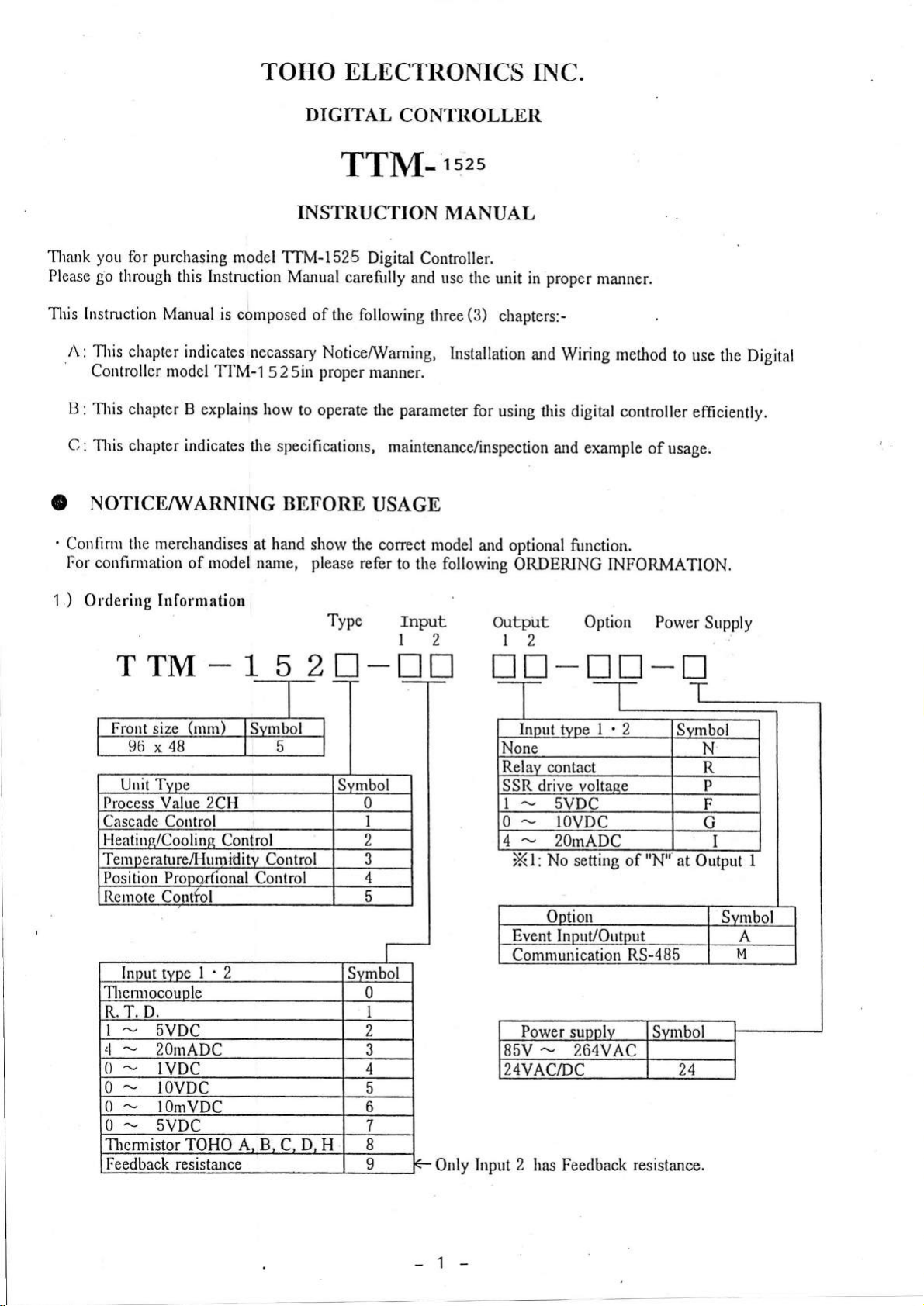
)
Ordering
Information
TTM
peratu
Tem
I
-
5VDC
15 ?rf-tr
relHumiditv
Control
Type
fnput
|
2
Output
Option
t2
SSR drive volt
No
Xt:
Communication RS-485
85V
-
setting
264
of
Power
"N''
Supply
at Output
1
Only Input
1-
2
Feedback resistance.
has
Page 2
2) Pacl<irtg Contents:
'
Check,
if all the
'
Instruction Manual(This
attachments are at
'FittingMetals"
Unit seal
'
your
booklet)
hand.
'lset
'I
'
1
booklet
sealpaper
Iu case anv of
'
Please bc
the
noted
above are
that types of
missins or
Input
l-lou,cver, the types of Thermocouple and
' Please
'
Copy or
hand
Reprint
over this
Instruction
of this
Manual
manual,
a
different
Output cannot be
and
R. T. D. input
to the
wholly or
partially,
' T'he contents of this manual may change without
'
Plcasc bc
3)
noted
that rve
Notice/Warning before usage:
' The
following symbol marks
not be responsible to all of the
shall
In case of
WARNINC
A
operator such as death, electrocution
In case of mishandling, it may
CAUTION
A
unit
or
are used
mishandling,
to the operator
included,
operator of unit and
is
prior
notice
in
serious danger may
slight
please
altered after receiving the
can be changed.
permitted.
not
in future.
defaults resulted
this Instruction
and
cause some damage
injury.
contact our business department.
unit.
keep it
with care.
by using of the
Manual for handling
occur to
a skin bum.
the
to the
unit.
this model
safely.
CAUTION
'
Do not
push
\l/ARNING
Makc
sure the
Mis rviring
Nevcr remodel
(i.
the keys
conect wiring connection before
may
by sharp
cause malfttnction
the
unit for
inq
connection
points
of the unit
prevention
FG
of
of malfunction
terminal.
e. Ball-point-pen,
turning
and may cause
on electricity.
unit
of
metals)
fire.
a
and fire.
prevention
for
of its malfunction.
-2
Page 3
on
I
t, roduc
rr
O
NO'TiCE/WARNING
o
Ordering Information'
1)
Packins
2)
3)
Notice/Warning
INSTALLATION
A.
1.
Panel
l.
l
1.
2 External
l)
t.
l.
4
l.
5
Wiring Method
2.
I 1'ernrinal Iayout
2.
t i
contents'
Installation
Parrel cut
and
of
external
Chart
Installation
Locat.ion
2.2 Notice/Warning
ll
lixarnples
2.
l) ltrput. l'2
0utput I
2)
Output 2
3)
z!)
OPDRATIC)N
B.
Event
Output l'2'
BEFORE
AND
dimensions
USAGE
'
before
lryIRING
Method
usage' '
-----'4
dimensions 4
Panel
cut dimensions
dimensions
--
Method 5
unit installation
of
wiring
for
wiring
at
of eaclt
-
wiring
---'---
IIETHOD
---
3. 0peration Flow and
3.1 Display
3.2
1
2
2
Each
l)BasicMode-
2)Set-up
3)Contro1 ConstanL
4)0ption
5)Feedback
6)Function Key
0ther displays
3.3
4. Definitions
4.1 Auto-tuning
PID Control
4
5
5
6
6
6
7
7
4.2
4.3 Event
4. 4 Additional
l)Event
2)Stand-by sequence
3)Process
4.5 Input
C.
SPECIFICATIONS
1 . General
2, Specification
3 .
Maintenance
conditions
Parameter Information
-
Mode
Setting
resistance Adjustment
Functions
Output
Functions
0utput Hold
Value(PV
display range & Setting
Specifications
Performance'
a.nd Inspect ion
Parameter
Setting
Mode
Setting
&
0N/0FF Control
Abnormal)
Mode
Mode
'
Standard and
--
' '
---'
-
Mode
-' 28
--'--'
range
''
-
-"'
.
1
15
17
20
24
27
27
28
28
29
29
29
4
29
30
31
31
33
I)oscript.ion
1.
0peration
1. I
Information
l.2
Change
I.3
Precaution
2.
Preparation
2. I
Preltaration
2.2
0ther Preparation
2.3
0ption
l)
2) Event.
llvent Input(SV
i
Event
i
Dvent
i
Function
3)
4) Blind
5)
Auto-tuning
of each
and Functions'
Key Information
of
Method
part
Display
of each Display
of Control'
of Set-up Mode
of Remote
Control
Sltting
Input/0utput
Input(RLN/READY)
Mode
Change)
0utput
Setting
Key
Setting
Mode
Setting
part
unit
Mode
--
------'
-----
---
-
-----"'11
-------'
-------'
--'
------
4. Example
7
B
B
B
9
9
12
13
1 3
3
1
3
1
3
1
4
1
Remote
Control
unit
-
33
-3:
Page 4
A. INSTALLATION
AND
WIRING
l. Panel
Installation Method:
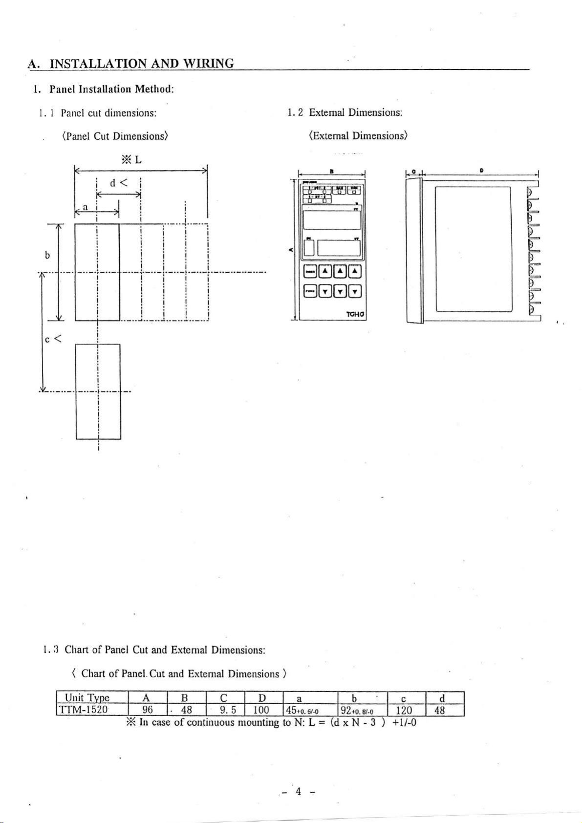
l. I Paucl cut dirneusions:
(Panel
.
Cut Dimensions)
1. 2
Extenral
(Extemal
Dimensrons:
Dimensions)
ll
l.
Chart of Panel
(
Ctrurt
Unit Tvoe A B
TTM-1520 96
Cut and Extental Dimensions:
Panel.Cut
of
and Extemal Dimensions
48 9.5
In case
of continuous
C
D
100 45*0.
mounting
rg
)
a
sr.o
to N: L
-4
=
b
92+0. el-o
xN-3
)
120
+l/-0
c d
4B
Page 5
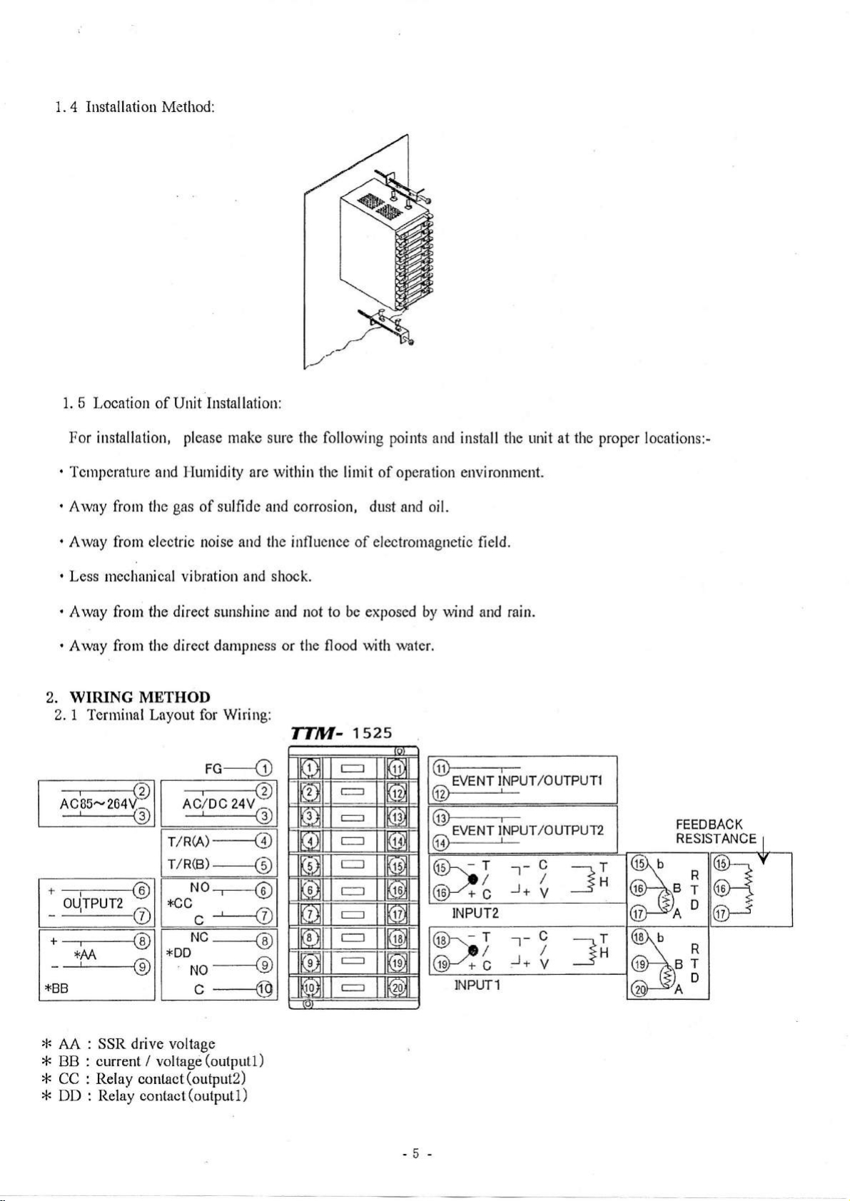
1. 4 Installation Method:
5
1.
Location of Unit Installation:
For
installation,
Tcnrperature and Flurnidity are within the linrit of operation environment.
'
.
Arvny from tlre
.
Alvay from electric
.
Less mechanical vibration
.
Arvay frorn
.
Away from tlre
please
gas
direct sunshine and not to be exposed by vvind and rain.
the
direct
make sure the following points
of sulfide and corrosion,
and the int'lttcnce of electromagnetic
noise
and shock.
darnplless
or the flood with watcr.
dust and oil.
and install thc unit at
field.
2. WIRING METHOD
Z. 1 Terminal Layout for
r/R(A)
r/R(B)
t
-------{O
OUTPUT2
'(D
+
--'--<o
*AA:
--r---tq
-
*BB
:
+CC
+DD
Wiring:
rc---c
----------f)
AC/DC
24V:.
-HU
----{D
----€)
NO
.-,._€
C
Nc
------{A
No
---{o
c
----<D
Y
TTM-
1s2s
ftD----------,-
TVENT TNPUT/OUTPUT1
I
(D-
63a)______]_
] TVeTTINPUT/OUTPUT2
(q+
(rs)----
x>/
(Xt
6d-\-
:
(H*
f
c
INPUT2
T
'D/
c
INPUTl
--
',
--'+
r-
,
--r+
C
/
V
9
/
V
the proper
----r
T
Jn
----Lr
tH
---:
locations:-
FEEDBACK
RESISTANCE
R
T
D
R
T
D
@--..
(6H
/,')
It I
Y
{
5
>F
AA
*
I]B
*CC
*DD
drive
SSR
current /
Relay contact
Relay contact
voltage
voltage
(outputl)
(output2)
(outputl
)
-5
Page 6
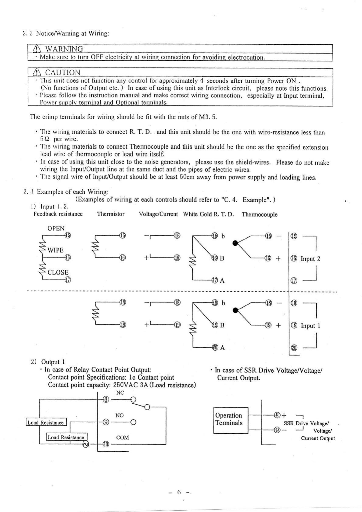
2. 2
NoticeAVaming at Wiring:
CAUTION
flris
uuit does
(No
functions
Please
Porver supply terminal
follow tlie
F
not
filnction any
Output etc.
of
instruction
electricity at
control for
In
)
manual and
Optional
and
wiring connection for
approxirnately
case of using
make
temrinals.
this unit
correct wiring
avoidinc electrocution.
4
seconds after tunring Power
Interlock
as
connection,
circuit,
please
especially
ON
note
this firnctions.
Input
at
.
tenninal,
Thc crirlp terminals
'
The rviring materials
5 O per
'
The rvinng materials
lead
'
ln case
rviring the
'
TIre signal
li
2.
Exanrples
l)
Input
Feedback resistance Thennistor
wire,
wire of thermocouple
of
of
1.2.
OPEN
for wiring should be fit with
connect R. T. D.
to
to connect Thermocouple
using
this
unit close
Input/Output
tvire of
each
Wiring:
(Exarnples
line
Input/Output
of
the nuts of M3.5.
and
this
and flris
lead
or
rviring at each controls
rvire itself.
noise
generators,
least SOcm
to
the
at the same duct ald
should be at
Voltage/Cunent
-r------@
+L@
unit
should
unit
pipes
the
should refer
White Gold R. T. D.
N'<-@-
S
be the
should be
please
use
flre shield-rvires. Please
of electric wires.
away from
to
"C.
s
'@
one with wire-resistance less
one
the
porver
supply
4.
Exampte".
Thermocouple
\---@
L_*^
as the specified
do not
and loading
)
@r
+
@l
than
extensiorr
make
lines.
2
Input
2)
Output
' In
case of Relay
Contact
Contact
I
point
Specifications:
point
capacity:
Contact
Point Output:
1c
Contact
250VAC 3A
NC
_c
-rc-l
Nol
----o
coM
point
(Load
resistance)
I
I
I
N*o
\,
s
L-*^
In
Current Ouput.
Operation
Terminals
^--@
\-*.
case
of SSR
-
Drive
VtlltageA/oltage/
@r
@
+-1
SSR Drive
J
Input
__l
Voltage/
Currcnt
I
Voltagc/
Output
-6
Page 7
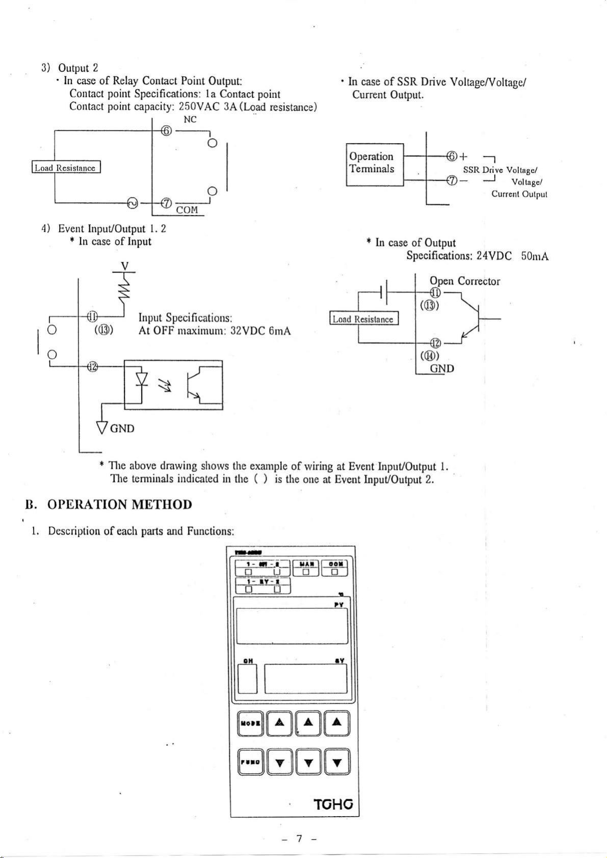
3)
Output
'
4)
Event InpuVoutput l.2
2
In case of Relay
In case
(@)
point
point
of
Contact
Contact
*
Contact Point
Specifications:
capacity:
Output:
la
250VAC
NC
Contact point
3A
o
Input
Input
Specifications:
At OFF maximum: 32VDC
(Load
resistarce)
6rnA
ln
case of SSR Drive
*
In
case of
Output.
Specifications:
Current
Voltagef/oltage/
+--1
SSR
Output
Corrector
Drive Voltagci
Voltage/
Current
24VDC
Output
50mA
GND
*
Tlte
above drawing
The
tenninals
OPBRATION METHOD
B.
l.
Description
of each
parts
indicated
Functions:
and
shotvs
in
the example
(
the
fr- rl
l--E--u-
T-i- rY-r-l
is
)
-i-ll-
of lviring
the one
u^--ll-
lfE_l[
at
tE_:El
o,l
nn
Event Input/Output
at
Event
Input/Output
oorl
-.l
p
i
.Y
1.
2.
@tr8tr
@BtrB
7-
Page 8
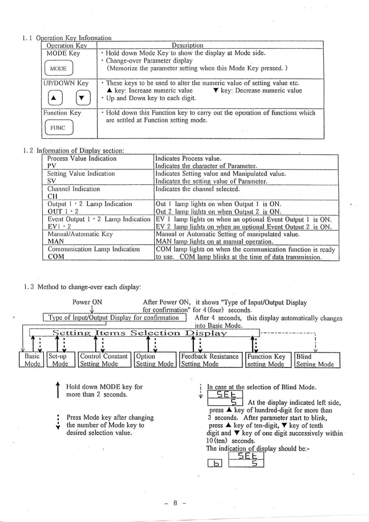
1.10
Ooeration
MODE
Key
In
Kev
' IJold
'
down
Change-over
(Menrorize
Description
Mode Key to show the
Parameter display
parameter
the
setting
display
rvhen
at Mode
Mode Key
this
side.
pressed.
)
1.2 ln
'
UP/DOWN Key
EO
Function Key
fonnation
Process Value Indication
PV
Setting Value Indication
SV
Chanrtel Indication
of
Di
These keys to
A
key: Lrcrease numeric value
and
Up
'
Hold down this
are settled
secilon
ctr
Output
I' 2
La.nrp Indication
ou'[1.2
Everrt
Outptfi
.2
EVt
Manual/Automatic
IVIAN
Corrrntuuication Lanrp Iudication
COM
|' 2
Larnp
I(cy
Indication
Down
at
to
used
be
key to
Futrction key to
Function
Indicates Process
Indicates the
Indicates
Indicates the
Indicates
Out
Out
EV
EV 2 liunp
Mauual
alter the
each digit.
setting
I
lunp lights
2 lamu
I
larnp lights
MAN lanru lishts
COM lanrp lights
to use.
nuureric
Y key:
carry
out the operation of frrnctions which
mode.
value.
character of
Setting
tlie channel selected.
or
COM
value
settins
on
lishts
on rvhen Outout
on when an
lights
on rvhen
Autontatic
on at nranual ooeratiou.
on when the communication
lamp
and
value
rvhen
Setting of ma-uipulated value.
blinks at the time
value of setting value etc.
Decrease numeric value
Pararneter.
Manipulated
Paraueter.
of
Output I is ON.
optional
an
optional Event Output 2
2
value.
is
ON.
Event
of
Output
function
data
trarsmission.
I
is
is ON.
is ready
ON.
l. 3
Method
Sr:ttire
to change-over each display:
Porver
ON After Power
terns
Control
Hold
down MODE key for
nrore
t
I
I
I
V
than
Press Mode key
the
number of Mode
desired
'Constant
2
seconds.
selection
after
value.
Sel
changing
key
to
it
ON,
iotr" for 4
Feedback
shows
After 4
i
i l--trE-tr]
"Type
(four)
secouds, this
Resistance
Il case at
of
seconds.
Function Key
the selection of
f--51
A
press
3
seconds. After
press A
digit and Y key
10(ten)
The indication
key of hundred-digit
key
of ten-digit,
seconds.
rtrtril
tE
l---E-l
InpuUoutput
display automatically
At ilre
parameter
of one digit
of
display
Display
Blind
display indicated
start to
key
V
successively
should be:-
I
I
Blind
ine Mode
Mode.
for more
blink,
of tenth
chzurges
left
side,
than
within
-B
Page 9
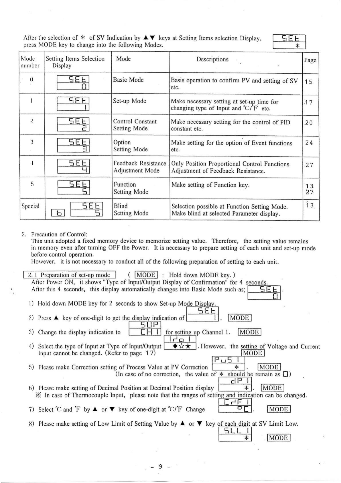
After
the selection of
press
MODE key
*
change into
to
of SV Indication
following
the
by
A
V keys
Modes.
at Setting Items
selection Display,
Modc
ntrnrber
0
I
?.
,)
.)
I
5
Special
Setting Items
Display
E
Selection
Mode
Basic
Mode
Set-up
Control
Setting Mode
Option
Setting Mode
Feedback
Adjustment
Function
Setting
Blind
Setting Mode
Mode
Constant
Resistance
Mode
Mode
Descriptions
Basis
operation
etc.
Make necessary
changing
Make necessary
constant
Make
etc.
Only Position
Adjustment
Make
Selection
Make blind
type of Input
etc.
setting
for
Proportional
of
setting
of Function
possible
at selected Parameter
to confirm PV
setting at set-up
'CI'F
and
setting
Feedback
for
the
the
option of Event
Control
Resistance.
key.
at Function
and setting
of
time for
etc.
control of
Setting Mode.
display.
PID
functions
Functions.
SV
Page
15
17
20
24
.21
13
2l
iz
2.. Precaution of Control:
This unit adopted a
in menrory even
bcfore control operation.
Horvever, it is not
2.rP
ion of
fixed memory device
turning
after
necessary to condnct
set-up
After Porver ON, it shorvs "Type
After this
l) I-lold
))
Pre
3)
Change the display
,l)
Select tlre rype of
Input
5)
ri)
zl
seconds, this display
MODE key for
dorvn
I
key of one-digit to
ss
Input
cannot be changed.
indication
the
OFF
mode
2
set
Type of Input/Output
at
(Refer
Power. It is
(
lMotE I
of
Input/Output Display
automatically
seconds
thediq+#f;Ecation
to
fTFl-l-l
page
to
memorize
to
of the follorving
all
shovv Set-up MolglDjfpley-
to
1
7)
setting
necessary
Hold
:
changes into Basic Mode
value.
to
preparation
dorvn MODE key.
of
Confinnation" for
_EEEI
of
I
for
settinq up Channel
i-l'
tr,
fi7
I
<)**
I.
Therefore,
prepare
I
I
Holever,
the
setting
setting of each
of
setting
such as;
)
to
4
seconds.
each unit.
f!--EEEI
l---Til
.
I
.
lMopE I
value remains
unit and set-up mode
Voltage
remain
as
il )
and Current
lMopEl
can be
changed.
7)
Select
r.t
Please make
)
"C
and
'F
by
setting
A
or V key
Lorv Limit
of
of
one-digit at'CfF
of Setting Value by
9-
Change
A
or V kev
lNropEl
of
'rErrTl
each
diqit
at SV
Limit
f---l lmpEl
Low.
Page 10
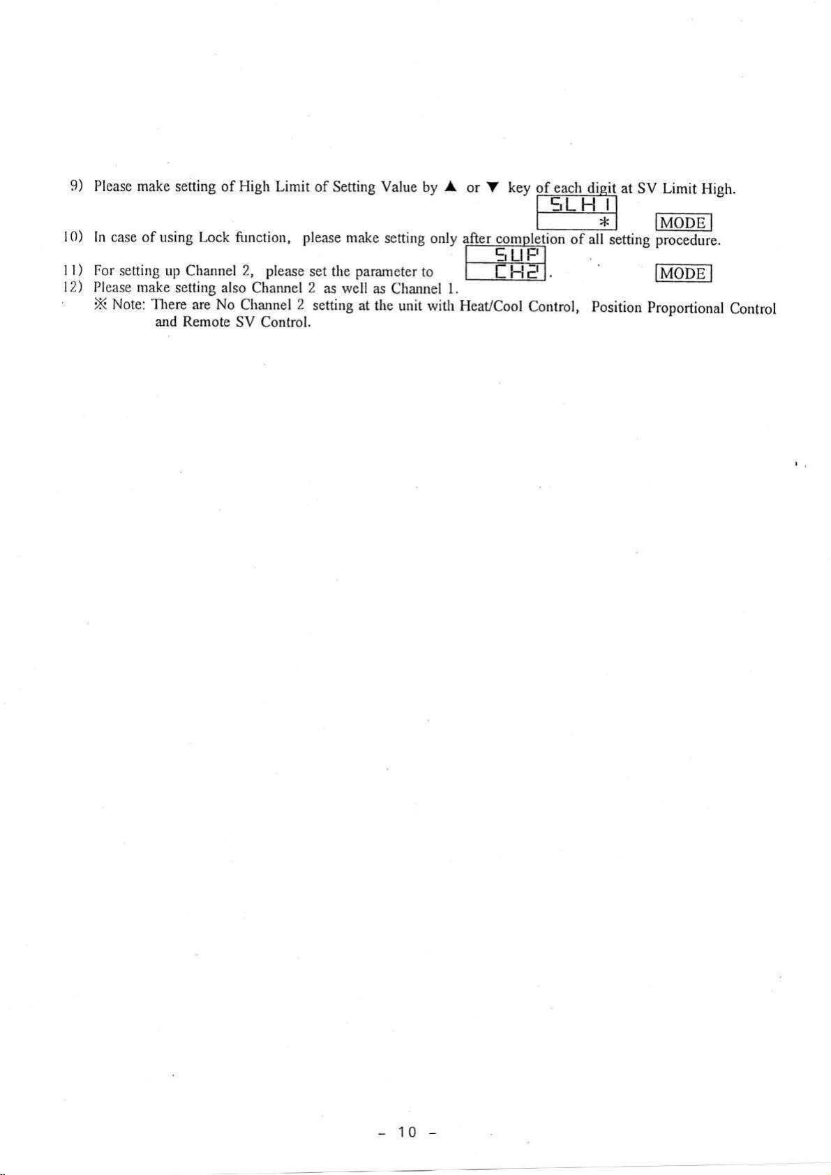
9)
Please make
setting of High Limit
of Setting Value
by
A
or V
key
of each
-rtrtFi-i-l
dieit
at SV Limit
High.
l0)
I
12)
t)
In case
For
Please
X
of using Lock
setting up
make setting
Note: There
and Remote
Channel
also
are No
function,
2, please
Channel
Channel
SV Control.
please
set the
2
2
setting
as
well
make
setting
parameter
as
Channel
at the
only
to
1.
unit
with HeaVCool
f--ak I
rmpletion
Ii-F-t
E
Control,
of all
setting procedure.
Position
lMOpEl
mpEl
Proportional
Control
10
Page 11
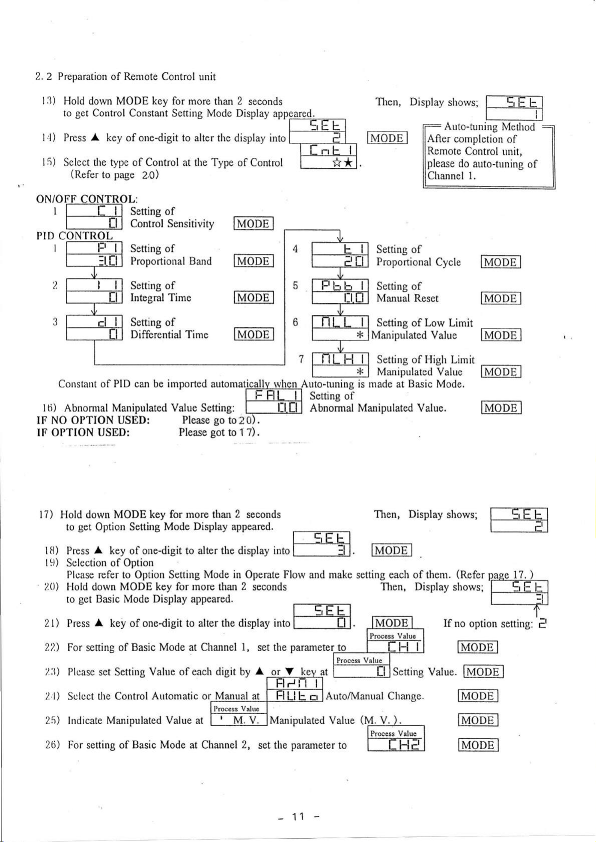
2.2
Preparation of Remote Control
l3)
Hold dorvn MODE key for more
get
to
Control Constant Setting Mode Display
I l)
l5)
ON/OFF CONTROL:
I
PID
CONTROL
I
A
Press
Select
(Refer
f-Tll
l--T1l
key of one-digit to alterthe
the type of Control at the Type
page
to
2,0)
Seftins of
contrSl Sensitivity
Setting of
Proportional Band
unit
2
than
seconds
display intol
of Control
tltloDE I
mopE I
appeared.
rE-TtrI
_LGE-N
I
E
**
I
Then,
lMopEl
I
Setting of
Proportional
Display
shows;
Auto-tuning
After completion
Remote
please
Channel
do
Cycle
f=EE
r--_]-l
Control
auto-tr"rning
1.
tMopEl
Method
of
unit,
of
Setting of
Integral Time
Setting
Differential Time
Coustant of
lti)
Abnomal
PID
can
Manipulated
IF NO OPTION USED:
IF
OPTION
17)
fi)
I
t .L))
20)
I-lold down
to
Press
Sclection
Plcase refer to Option Setting
USED:
MODE key
get
Option Setting
A
key
of Option
of one-digit to
llv(oDE
of
lMopE I
be irnported
Value
Please
for
Mode Display appeared.
autonratically
Setting:
Please
go
to
got
to 1
more than
alter
the
Mode in Operate
Z
2
display into
I
rvhen
ft:J-fif-n
I
0).
7).
seconds
l:l.tl
f{-.ffLl
I
l---Tl. mopE
Flow and
Auto-funing is made at
Sering
Abnormal
I
oI
-tl-l_t
make
Setting
Manual Reset
Setting of Low
Manipulated
Setting of High
Manipulated
Manipulated Value.
Then, Display
setting each of them.
of
Basic
I
Value
Value
Mode.
shows;
Limit
Limit
(Refer
ij"j1,tx?,Y,??IJil'$ru::'.lr2iecondsrE-Tilt1,.n,Displayslrows;ry
IMoDE I
lMopE-]
mopE
lMopEl
page
I
17.
)
2l)
2,?,)
2:i)
21)
25)
26)
A
Press
For setting of
Plcase set Setting Value
Plcase set Setting Value
Sclcct the Control
Indicate
For setting of Basic Mode at
key
of one-digit
Basic Mode at Channel
Manipulated Value ut
to alter the
display into
1,
of each digit by A or V
of each digit by
Automatic or Maqu4[
lrtu.lrlManipulated
Channel
2,
set
the
A
or V
|-FIFN_I
ut_.ff-f
set the
-
l------Ti-|. llvIODE I
parameteUlo
key
at
[-----EIl
crlAuto/I4anual
Lll=
Value
l--EFiJl
Setting
Change.
(V.V:)-,--
[p,*;*,r*l
parameter
11
to
I
t
He
If
Value.
I
no
option
TMODE I
IMODEI
ffiODE I
ffiODE
mopEl
setting:
I
f,
Page 12

2.3
l)
In
:!
tl
5
ri
7
Option
Setting Mode:
Option
OP
:l
Event I
PV Event I
PV Event I
LOW
PV Event I
HIGH
PV
Event
sensitivity
I
DI
(Refer
selection
Number
Function
setting
setting
1
function
to
Select Option function
MODE
B
In
)
Key.
case
4
2
page
F':E
Event
PV
PV
LOW
PV
HIGH
PV
sensitivity
DI
A
by
2
Event 2
Event 2
setting
Event 2
setting
Event 2
2
function
or
V key nnd next
Inc
t4
16
t7
1B
Retunr
go
to next
:El
Communication
Paraneter
Communication
Speed
Communication
Address
Response
Time
Communication/
Local
I
to
Display
Delay
Clrange
by
I
Return
to
I
Retum
to
1
-
12
Page 13

2)
Event Input(SV Change):
I
Event
Input/Output
(At
Event
1)
T-E;;I I
'
Displays only when Event
I
is Digital
Inprrt
and
DI
I
Function
r-ilEt
Plcase nrake setting
'
Displays only
Plcase make
Ptcase make setting
Event Input
?
setting
(RUN/READY)
.PlcasesetDIlfrrnctiontoffiRI.JN/READYwhenEvent1is
i In case
.
Displays when
of using
of SV2
Event 2
when
SV3
of
of SV4
Event Output:
1
Event
[-[[lsvz.
t--T;E]
T-tr;TI
[---TllSvs.
ffi
:
T-E;I
is
I
e
I
is Digital
run.
Digital
llt4ODEl
Input and DI
nutopEl
mopE
Output.
2 Function
I
E-TF-I
|
l_-.t;-=Fl
I
|
SV Ctrange.
lis
I
SV
lis
Change.
.Sclect
'
Please
3) Function
ff--=i-tT:-l
f-T-*Tl
complete each setting.
Key
Plcase set the
r-Fln
I
4) Blind
I At the display of
2 Displays
:]
Blind Mode Selection
tl I
Setting
[]
PV EventOutput
Setting Mode.
parameter
Make setting at
Mode:
to
_
rEEI
I
blinking
V
ald
rEil
f---El
Ih]
I
tunction.
Function Key Setting Mode.
down
A
in
tum within
hold
E
L
parameter. Then,
key
of one-digit
.
n\4oDEl
TEEEEI
f--*l
IMODEI
key of
press quickly
*
:
After setting
one-digit,
parameter.
hundred
A
l0
seconds.
(Refertopage
(Refer
digit
key of ten digit,
press
to
for
of desired Blind mode
MODE key
29)
page
27
more thar
to
Y
)
3
seconds to
key of
A
by
get
appear selected
start
digit
ten
Y key of
4
f----Xl Btind
l--c,l-trI
Tl
After setting of
shut
down the
Settins
Blind,
electric
power.
-
X
trr
c,l:
13
:
Selected Parameter
:
Blind the selected
rr
:
No blind
l:
parameter.
the selected
parameter.
Page 14

5)
Auto-tuning Setting:
No Auto-tuning is
possible when the
control is set at ON/OFF
Control.
I Starting
l)
2.) Fix
3)
nrethod
each
Set
the setting
Shift the
parameter
display to
one-digit
It
takes some time to execute
Auto-tLrning:
of
of
value at
Auto-tuning Starting Display of
for more than
"Control
"Basic
2
Notc: ' Auto-hrning operation should
(lnput/Output
intermediate termination
of
operation.
indication
"E. - il"
of Cancellatiorr
FLOW AND
at l{eating/Cooling
only
Opening
only at
only when Cooling
only at Cascade Control unit.
Charge" is
only when Event Option exists and also more
at Current/Voltage Input
only
only
only when Event
only when Event
only when Event
only when
only when Event 1 is
only rvhen Event
only lvhen Event 2 is set at
only
only when Event 2 is
only when Event 2 is
only when Communication
only at
PARAMETER:
Disulav
SV rvhile
at Remote
Position
at
Heating/Cooling Control unit.
Cooling
Event Option exists and
when
selected.
Current/Voltage Output unit.
at ON/OFF Control.
when Option exists.
Event
when Event 2 is
Feedback Resistance Input.
'
'
' The method
3.
OPERATION
:1,
I Display
Di I
Svnrbol
,<l
>l<
2
>l<
lJ
>l<
4
,F5
>l<
fi
>F7
>l<
ll
>l<
!)
,<lo
*l
I
>l<12
.)
)kl
r)
,<14
*r5
,<lri
>FL7
>1.18
,l<19
4<20
7:21
>l<'2
2
,l-
L t)
>l<24
>F25
d<26
>l<27
*28
d<29
connection
In case
Ar"rto-tun ing
lu case of the snapping of a wire or
error
Auto-tuning operation takes too
Condition
No
display
Displays Process Humidity
Displays Remote
Displays
Displays
No
display at ON/OFF Control.
Displays
No
display when Cooling Output
No display when
Displays
Displays
Displays only
"SV
Displays
"SV Change" are selected.
No display
No
display at
Displays
Displays
Displays
Displays
Displays
Displays
Displays
Displavs
Displays
Displays
Displays
Displays
Displays
Displavs
Constant Setting Mode" and
Mode".
seconds
Auto-tuning.
etc.
to start Auto-tuning.
be
)
only after completion
nrade
of Auto-tuning, PID
disconnection
to be appeared. The same
much times.
is sarne as the one of
Condition
Control unit,
zurd Setting
remote
Control
Proportional
Output
Output is
1
exists.
I
is
set
I
is
set
I
is set at
set
2
exists.
set at
set at
set at
Hurnidity
control on Remote
unit.
Control
is
at
set
ON/OFF Control.
is set at Current/Voltage
at ON/OFF
set
unit.
at
at
"PV
"Low
Event".
Limit"
"High
at
"DI".
Event".
"PV
Limit"
"Low
"High Limit"
"DI".
function exists.
"Basic
of Output while
starting
Position
Temperature/Humidity
at
unit.
also more
of
Limit"
of
of
of
"Option
Mode"
Constant
error
Proportional
and hold down
parameter
of
indication to be
method.
Control unit.
Output unit.
Control.
(one)
I
than
(two)
2
than
Event".
"PV
Event".
"PV
Event".
"PV
Event".
"PV
Setting
remains sanle
Mode".
setting
Auto-tuning
appeared
Control
and Remote
Control unit.
function
of "DI Event"
function of
A
and wiring
as the one set before
or V
key
of
operation, Auto-tuning
when
Control unit.
and
"DI
Event"
and
14
Page 15

3.
2 Each Parameter
l) Basic
No.
I
?,
l
4
Mode
ndications
Parameter
Process Value
Channel
I
Process
Cl{
Setting ValLre(SV)
CHI ,A.Lrto/Manual
C!rq!gq
I
Local/Remote
CIJ
Change
Selection
Value
Information
Descriptions
Select
digit.
f
f
Displays
Setting Value
Settingrange:
Setting unil Thermocouple
Change of Automatic
Channel
Select
digit.
"f l{
I selection: It is
I-l
Process
selection: It
F!E
Process
"Fl
Flur
E rr
I" or
Value at
value at Channel 2
Process
(SV).
5LL
R. T.
D. /Thermistor Input
Current/Voltage
1.
urE
Er"
selection: Automatic
l-lFlr, selection: Manual
Change of
Select
digit.
-
Local
l-lEr"
"r
E
L f L
E
selection: Local
l-ltrr selection: Remote
"f
is
Value
Setting
or
Mode
or'L
HE"
possible
Channel
possible
(PV)
by each
l-ELH
Input
Input I
Control
"ilFlrr"
Remote
and
f
L
AV
by
change
to
1
and Basic Mode.
to change
and Basic Mode.
at Channel
A
I
-'------'----
".'
Manual
and
AV
by
Control
Control
Mode
AV
by
"
operation
operation
key of
the
the
I
and Change
V keys.
0. 1"C
Control
key
ofone-
Channel
at
key
of one-
one-
display of
display of
('F)
1"C
('F)
disit
at
Initial
Value
TC
'rr
R,i.D.rri
-----t]-tl
I.V
Flurtcr
I
[H
L IL
Display
Conditions
Remarks
*1
I
*2
>F3
LI
rt
tl
*4
and
5
ti
7
u
Process
CHI
MrUUp,Ll atgd _V_qlqe_
Manipulated Value
CHI Process Value
Q_ogl_ile _O_uJptlt_ _ _ _
I
CH
Auto-tuning
start.
SV2
CI-II
Value
Displays
Value
Manipulated
percentage.
Displays Process
Value of Cooling
Start Auto-tuning at Channel
of one-digit for more
If
Process
of Output
rr selection: Start Auto-tuning at Channel
trr
of
any
1.
Value of Output
display selected
at Channel
Value
I
to
Value at Channel
Output.
1.
Hold
2
than
to start Auto-tuning.
while Auto-tuning, it
be displayed
r----Frtrl
In
case of cancellation, Cancellation
made same manner as Start of Auto-tunine.
Change
Settingftmse:
Setting unit:
of SV2 Setting Value.
ELL
Thermocouple Input
R. T. D.
Current/Voltage
Settine bv each
l-ELFI I
/Thermistor
AV
kevs.
"""--""'
Input
Input
1
and Manipulated
I
and Manipulated
AY
down
(rr
!: !:
)
1"C
""-"
0.
l"C
I
in
key
L
shows
can be
('F)
('F)
digit
c,l=
TC
R.T.D.TFI
_____t;t-[-
LV
*5
*7
*6
l:
*12
I
n
15
Page 16

I
CIJI SV3
l0
ll
t?.
,)
l
l.)
lrl Auto-huring
SV4CHI
Proccss Value
CI-ll
(SV)
Sclting
CI-I2
ChanAe
Value
Auto/lManual
Process Value
CI-12
pt! qtg{
\4r11r1
f,'r*----
r---i_
hl r rr i nr rl rteA\/r lr re
CH2
start.
""1*
_V_4!'le-
I
r
Change
Settingrange:
Setting unit:
Churge
Settingrange:
Setting unit:
Displays Process
Setting
Change
Channel
Select " Fl
digit.
of SV3
Settine
of SV4 Setting
Settins bv
Value
Settingrange:
Selting unit:
of
2.
Flur
E cr
Setting
ELL
Thennocouple
R. T. D. /Themtistor
Cunentfy'oltage
bv each
5LL
Thermocouple Input
R. T. D. firennistor
Current/Voltage
each
(SV).
l-5LFl
AY
l-EL!-l
AV
Value
Setting by each
5LL
Thennocouple
T. D.
R.
Current/Voltaqe
Automatic Control and
ur t. Er
selection:
firermistor
or " l-l Fl rr
"
ll Flr, selection:
Displays Process Value of
Value
_
Manipulated Value
percentage.
of
at Output
Start Auto-tuning at Channel
one-digit
Auto-tuning.
1.
Output
of
for more than
Value at Channel
""""""'
Input
Input
1.
I
l"C
"""' 0.
Input
keys.
Value at Channel
I
l.
"'-" l"C
"""'
Input
0.
Input
kevs,
(PV)
of Chamel
A
V keys.
2
and
l-ErLl-l I
""""""'
Input
Input
-"""
Iunut
Manual
A
by
"
Automatic Control
Manual Control
Channel 2 and Manipulated
I
to be
2.
Hold dorvn
2
to
start
Control at
Y
key of one-
displayed in
A
(cr
r')
('F)
l"C
1
digit
('F)
l"C
1
digit
Change
l"C
0. l.C
I
disit
Y key
('F)
('F)
('F
('F)
IC
R.T.D.TtI
_-_-_l=1.[-
l.v
1'C
_____--tr.
R.T.D.TI.I
---__l=l.E-
I.V
'lc
R.T.D.TII
)
_____[rE
I.V
Flurtcr
tr.
tl
rr
tt
il
n
crFF
813
,k13
*l
*3
*1
x1
*t
*6
t5
cr-t2 svz Change of
Setting
l6
t7
SV3
CI.Iz
CI12 SV4 Change
In case of cancellation,
made sune
Setting unit:
Settinq bv
Change of
Setting range:
Setting unit:
Settinc bv
Setting Value
Setting
Setting unit:
.
mauner
SV2
range:
Themocouple Input
R. T. D. /Themristor
Current/Voltage
each
SV3 Setting Value at Channel
Themrocouple Input
R. T. D.
Current/Voltage
each
of SVrl Setting Value at
(SV)
range:
R. T.
Current/Voltase
as
Setting
L L E-5L
E
AV
L E
EL
/Thermistor
A
V kevs.
.
Setting by each
5L L E-EL
Thennocouple
D.
firenrristor
Czurcellation
Start of Auto-tunins.
Value
at
(c,
Channel 2.
He
""""""'
"""'
Input
Input I
keys.
-5L
l-lE
Input
Input
Channel 2.
l-!E]
Input
Input
"""-'-""
"""'
"""'-""
A
V keys.
""""""'
"""'
Input 1
F F
0.
2.
0. I'C
)
l,C
l'C
l'C
1
1"C
0.
can be
('F)
('F)
digit
('F)
('F)
digit
('F
l'C
dieit
)
('F)
TC
R. T. D
I.V
TC
R.T.D.TI{
.'ilt
_____l=l.u
_-___l=1.[-
I.V
'tc
.
R.T.D.1'I'I
_____[tn
I.V
*1
*12
fl
fl
>F1
*13
I
rr
*1
)F13
I
n
-
16
Page 17

2.)
Set-up
,-u
ndications
Mode
No.
I
Set-up Mode
C.ha!,r
1.
CHI Type of
lrp_qtlQgtp-u_t
g
lnput
l_e-c!
l_
$ 9
type of
<)
'l
-t
:r :r
_lL!
-r5
:rE
:l '-l
In
I
I JPtl
Select
i-op_
f
f
Displays
Tltermocouple
Input
type
1}enrrocouple
K
"[!-!
digit.
! selection: It is
i-l
Process
selection: It
!*ie
Process
the type of
:
i
Symbol of Input
J Themrocour:le
Thermocouple
E
Thermocouple
T
R Thermocouple
S Themrocouple
Thermocouple
N
WSREAMz6RE
Pr100
00
Descriptions
I
or
"
"f !+I"
possible
Value
of Channel
possible
is
value of Chzurnel
Input/Output.
type
R. T. D. Input
'
AV
by
change
to
I
to change
2
and Basic Mode.
type of
) [nnrrt fvne
I
-5VDC
4-20mADC
O-
O-IOVDC
0-10mVDC
0-5VDC
E
E
,-l
Ll
I.nitial
Value
key
of one-
the display
ald Basic
the display of
of
Mode.
Unit
Type
InpuU
Output
Voltage ' Cunent Input
IVDC
Display
Conditions
Remarks
*1
I
[!-l
used.
of
EE
EI
Select
Mode
(Displays
4
seconds
Power
type of Thermistor
Inout
i
A
fvue
B
I
tvoe
C tvpe
D
I{
tvoe
type
LI
Set-up
tvne
only
after
input.
and
)
r)
CHI
PV
I CHI
P_e_c!rfr+!.
Conection
!99
i_ti_o_n_
:
Symbol of Ouput
*'
each
or
2
tvpe
contact
Output
Vah.re at Channel
100- 100
-
('F)
1"C
1
digit
A
kevs.
V
l:l.fl' by
"
* Output
None
]- Relav
SSR Drive Voltase Outout
i:r
Voltase Output
LI
t
I
Current
Conection
Setting range:
Sening unit:
Settins bv
Display selection of decimal
Select
_
of Process
" fl"
2
type
Output
or
A
100.
or
-
0. 1"C
point
of one-digit.
Y key of
*
1.
0- 100.
('F)
one-digit.
:
Symbol of
*
Relav contact
r
!:l SSR
Voltace Output
LI
I
I
Current
0
Output
Output
Drive
TC
R.T.D.TH
_____l=1.[-
I,V
I.V
R.T.D.TH
type
1
tvpe
Outuut
Voltase Output
Output
-El
n
fl
rtn
-
17
:
Page 18

5
CHl
'Q/'F
ri
CHI
SV Lirnit Low
I
CHI
$!
8
cl-l
Sqt-turg
Change
Lirnit High
I
qf
Lock
Selection of
Select
Setting
Setting
rrEr
l
rrruLUuPtE
Setting range:
range High.
more
be
)'rn f--,,1
r\ r u rrrPul
Setting range:
range High.
more
be
l/^l+^
-^//a..--^,.]
b
Setting
rarge High.
be more
'I'|
r rrLr
^-*:.+^-
trrrJtut rrrPut
Setting range:
range High.
nrore
be
Setting of High Lirnit
Setting
1-t. I
rrrr
l
rrruLUuPrc rrIPu
Setting rzmge:
range High.
be more than
r\ r L,
Setting range:
range High,
more
be
\/^lr^
-^//-.,--^,.+
5L'
Setting range:
range
nrore
be
Tl"^--:.+^- r-^..G
t rrLr
rrllDtur
Setting range:
range
be more
Select the
Select
Symbol
"C
f
Low
by
display
,
or
Limit
AV
rtrlJu
"E
keys.
I'
of
L-r
SV Setting range
But
the
('F).
50'C
than
SV
Setting
But
the difference
5. 0"C
than
range:
than
than
by
rrrpul
than
f
-^,,+
rPu
SV Setting range
But
the difference
50
digits.
I--..+
SV Setting range
But
the difference
5. 0"C
AV
keys.
SV Setting range
But
the difference
('F).
50"C
SV
Setting range
But
the difference
5. 0"C
r-^,.+
SV Setting range
High.
than
But
the difference
50
digits.
rlrPul
SV Setting range
High. But
than
type of
the
5. 0C
Lock function
"fl-E" by
Tvpe
OFF
I
I All
E
Ll
=l
tr,
E, AII Lock
Lock
Basic
Mode
Set-up Mode
Control Constant
Option
'F
and
l=
A
by
"
of Setting
difference
range
('F).
('F).
of
Setting Value
('F).
Pu
difference
('F).
AV
key
of
Loc\
Lock
Lock
Mode Lock
Settinq Lock
except
Settins
display
V
Value
Low
witn
Low
with
Low
rvith
Low
with
Low
with
Low
rvith
Low
with
Low
rvith
at Channel
key
of one-digit.
at
SV
-
5 L F!
SV
-
E
L
SV
-
ErL
SV
-
5 L l-!
at Channel 1.
SV
-
5
L L
SV
-
E L
SV Setting
-
5
L L
SV
-
E
L L
at Channel 1
of one-digit.
Value
Channel
Setting
I
should
Setting
I should
ll
Setting
I
l-l
should
Setting
I
should
Setting
I strould
Setting
I
should
L
I should
Setting
I
should
(SV)
1.
*14
Ef
1.
tl
-tI
l-t.t!
-rI
t:t.[
-tI
t:I.tl
tetlil
t-t.fl
5 il
Ertlfltl
rfl
r:r.il
I
-
1B
Page 19

9
CHZ
lqp-q(Qutp-u-t-
l0
CI.I2
PV
Correction
il
CtI2
Decinral Position
t2
CHz
ll{'n
Type
of
- - -
-Qhqnge----
Same
as the
Same
as CHI PV
Setting
Sarne Decimal
Same as CHI
by each
Select by
Select by
A
A
type
of Input/Output
Correction.
AY
keys.
as the
one of
V key
Y key
"C/'F
of one-digit.
Change
of one-digit.
CH1.
at CHl.
Type
of
Input/
Qutput
used
TC
-______tr.
R.T.D.TH
_____t=LEl-
I.V
TC
R.T.D.TH
_____l=t.E.
I.V
L:If
*1
*1
fl
*1
n
I-l
*1
*14
l3
l4
15
CH2
SV Limit
CH2
SY-
I-j,r,jt_Hjgb_
CI-I2
Setting of
Lorv
Lock
Same
as
CHI
Setting by
Same
as CHl SV
Setting by
Same
as CHI
Select by
SV
AY
AV
Lock
A
V key of
Limit Low.
keys.
Limit
keys.
Setting.
High.
one-digit.
TC
R.T.D.TH
_____l=l.E-
I.V
TC
--l-E'-tltl-
R,T.D
- - -ErE-tl.
I.V
_EJ[!EI
TH
tnnn
*1
tl
fl
)F1
*1
n
-
19
:
Page 20

:t)
Control
lndications
Constant Setti
Mode
No.
t
Set-rrp Mode
Channel Selection
?.
,)
I
CL{
I_vp!r_qleq!!r_ol
CHI
Prqp_q(r_otrgl F_ry_d_
Select
digit.
f
f
Select the
-
"I
selection:
I
Fl
Constalt
selection:
l{
e
Constalt
Select
Select * by
*
* Type of Control
2
noints control
I
Temperature difference
T
Control
*Renrark
Setting
Setting
Setting unit:
Setting
range:0.
of
by
Descriptions
or
I"
l-l
type
by
l:
Proportional Band
A
Percentage
"f Fle"
possible
It is
Mode
at Channel
possible
It is
Mode at Channel 2.
of Control at Channel
A
V key
A
V
Temperature
temperature difference
Cliannel
key
V
1-200.
of one-digit.
key
of ten-digit.
difference
2
SV such as:
of each digit .
0
(%)
AV
by
to change the
L
to cltange
* Tvpe
I
;,
l! ON/OFF
Ll
control: It
between
CHI SV
at Channel
against
EL
Initial
Value
key
of one-
Control
the Control
1.
of Control
PID
Control Nonnal
PID Control Reverse
(Nomral
(Reverse
I
PV
CH2 SV.
ON/OFF
Control
Control
controls the
Channel
-
l.
L
-EL
l-l
Display
Conditions and
Remarks
!
f H
*Remark
IE
operation)
operation)
operation)
operation)
actual value
and
:l.tl
*1
1
of
*6
.l
CFII
!r1t_eg1ql_frpe_ _
;)
6
7
il
I
cll
Differential Time
CHl
1o_po_(
!
CHl
Control Sensitivity
I
CFI
Manual
i_op3r!
Reset
_Cy_cl e
Setting of
Setting by
Setting
Setting
Setting
Setting by
Setting range:
Setting unit: seconds
Setting of
Setting by
Setting range:
Setting
Setting of Control
Setting by
Setting rarlge:
Setting
Setting to add manipulated
value at Channel
Setting by
Seuing
Setting unit:
lntegral Time
A
key
V
range:
unit:
0-3600
seconds
Differential Tirne
of
A
V key of each digit
of each digit
0-3600
Proportional
A
Y key
of each digit
1- 120
unit:
seconds
Sensitivity at Channel 1.
A
key
Y
0-100
unit: Thermocouple Input
R. T. D.
Current/Voltage
A
V key
ftmge:
0.
%
of each digit
or
/Thennistor
1.
of
0-100.0
(percentage)
Channel
at
at Chalnel
Cycle
at Channel
0. 0-100. 0
Input
Input
value to
each digit
I
.
I
.
I
.
.
"""""'-'
'------
0. l"C
the manipulated
.
1"C
I
('F)
dieit
('F)
Relay
Contact
Point
e I
SSR
Drive
Voltagc
TC
-------tt'
R.T.D.TH
___-_l=1.[-
E
I.V
|J.I
*6
I
*6
I
*6
*15
*16
rr
lt
>k6
-20
Page 21

I
CIII
MV Limit Low
I0
ll
I
cl{
Xz! !_ !r11r 1t_llrglr _ _
Cl-ll
Abnonlal
Manipulated
Setting
Setting
Channel
Relay
Sening range: 0. 0
Setting unit:
Setting
Settinc unit:
Setting of Fligh
Charnel
Relay Contact
Setting
Sefting unit:
Setting range:
Setting unit: 7o
Setting of Abnonnal
of
Setting by
value
Setting
Setting unit:
of Low Limit
1.
Contact '
%
b
range:
range:
EE'
range:
-
7o
l.
'
MVLimit Lorv
%
MV Limit
A
0. 0-100.0
%
Manipulated
of
Setting
SSR
(percentage)
10
(nercentase)
Limit
Setting
SSR
(percentage)
(Dercentase)
V key of
(percentage)
by
Drive
MVLimit
-
P
MV Limit
-
of Manipulated
by
Drive
I
-
Manipulated value
each digit
Value
at
A
keys.
Y
Voltage Output
High
High
Value at
A
V keys.
Voltage Output
-100.0
1t0. 0
at Channel
.
*6
l:1.fl
-tn.fl
*6
- - - -
Ifll].tl
I ll:|.tl
I
t:t.I
1?.
I
CFI
Cooling Output
Prouortional Bald
r:-lrn
f---*
l:]
Cooling
llppg,tt-qlglcycle
l.'l
p_o_ol
ilg_
Egrqljetqtiviry
t5 CHI
Dcad Band
t(i
CI-II
9_o_oli1g_Qy1pr4_
MV Linrit Low
1
Output
Q1rlprlt- _ _
Setting of
Channel
Setting range:
Setting unit: Times
Setting of Cooling Output Proportional
Channel
Relay
Setting range:
Setting unit:
YoltaB,c,LurIclll rIrP
Setting range:
Settins unit:
Setting of Cooling
Channel
Sqtturc" range,:
Setting
Setting
Setting by
Settinc
S;ti,[ iu,,t:
Setting
Channel
-
Relay
Setting
Setting
voltage/uurrent
Setting
Settins
Cooling Output Proportional
1.
l.
Contact
l.
unit:
Setting by
0.
l-10.0
Setting
'
SSR
I
-120
seconds
I
-120
seconds
Output Control Sensitiviry at
Setting
(0,
0
0)
flle-ry1o_cp_up.lq
T.-n.
n.
Current/Voltace Input
rni.":'iii6 r-ti,
of Dead Band
A
V key of each digit
ranse:
100(- tCtO. 0)
-
AY
A
by
Drive
Yoltage
A
by
V
100 ( 100. 0)
-
_lnpUt_ _':
at Channel
Tlie;,i-.i-;l,ie- ilrpul
T. D. /Themristor
R.
Current/Voltase
Lorv
of
l.
Contact
raxge:
unit:
range:
unit: %
0.
%
-
Limit of
Setting by
'
SSR
0
-
(percentage)
rnput
10
-
(percentace)
Input
Manipulated Value at
Drive Voltage
MVLimit
MV Limit
key
A
Bzurd
at
key
of each digit.
Cycle at
Y
keys.
Output
each
of
pul
1.
-100(100.0)
j:'jrj:'j:'j
Input
Y
keys.
High
High
digit
-:'_: -::'_t-EG)_
--
r--- :---
0.
.
"""'
0. 1'C
Output
.
-t-.c('
p')
I
dieit
l:"p-(f)-
('F.)
I
dicit
*7
*B
:l.tl
*7
*8
*9
efl
e
x<7
x10
rI
_L:Lt!.
i1.n
l:t.I
LI
rr
ll
ri
*7
t-l
tt
*7
>l:
[J
_
-
-
)1
Page 22

t7
C_o-olipg-Qy!p-ut-
M-Y-Lul!-Ujsh
l8
CI{2
Type of Cqntrql
Setting
Channel
-
-
Relny Contact
Setting
Setting
Y
Setting range:
Settins unit: 7o
Same
of Low
range: Cooling
unit: %
Ortilge/uur[eltI
as
Limit of Mzuripulated
1.
Setting
' SSR Drive Voltage Output
(percentage)
rnput
Cooling
(nercentase)
Type
CHI
of Control.
A
V keys.
by
outllut MV
output MV
Value at
Limit Low
Limit
-110.
-100.0
0
*7
XB
I
t:t.[
I
*1
te
l9
CI{2
Proportional Band
20
cll2
'21
CH?
fle 1e_rltiql JU!e_ _
-D_i
,),)
CII2
po_r1
tq
P
totrg[ _Cy_c]
Same as CHI
Setting
as CHI
Same
Setting by
as
Same
Same
e_
CHI
Setting
as
Setting by
Proportional
A
Y
by
by
CHI
key of each digit
Integral
A
V key of each digit
Differential Time.
A
V key
Proportional Cycle.
A
V
key of each digit
Band
Tirne.
each digit
of
:t1
*6
:l.tl
*1
.
*6
n
*1
.
*6
I
Rclay Contact
.
Point
e n
SSR
Drivc
Voltagc
*1
*6
*15
e
o.)
1, \t
CI{2
Control
L
I
L
I
24
CH2
\,!4r11a.! _(qs_e!
Sensitivity
Same as CHI Control Sensitivity.
A
V
key
Manual Reset.
A
Y key of each digit
-
_ _ _
Setting by
Same
as CHI
Setting by
each digit
of
'tc
R.T.D.TH
____-t;10.
I.V
n
*1
*16
n
*1
*6
n.tl
'25
CI-I2
MV
Lirnit Low
Sarne as CHI
Setting by
MV Limit Low.
A
V key of
each
digit.
.
Rclay
SSR
_____[rI
I.V
-l
[[
x1
*6
-22.-
Page 23

26
CYT?
MV
I,ur:il
Hrglr
Sarne
as CHI MV Limit
Setting by
AV
High.
keys.
.
Relay
SSR
__tIL:rtl
*1
x6
t)1
LI
CHZ Seuing of
Abnonnal
Manipulated
,)o
Ll,
CH2 Cascade
Scaling
?..1)
CI-{2 Cascade
Sqalj,tg_H,gl,_____
:]0
CIl2 SV Setting
for
Cascade
AuJq:tltUUrA
Lorv
value
Same as CHI Abnormal
Setting by
Setting range:
Setting unit:
Setting
at Channel
r
rrcr llruLuul"rrt rulrut
Setting range:
rarge
High. But
be more
y
r\
r
rrrPut
Setting range:
range High. But
be more
\/^l+^-^//r.,....^-l f ......+
b
Setting range:
range High. But the
be more
rrtr
I
lrrrstur
Setting range: SV
range High. But
be more than
Setting of Cascade
at Channel
l uEr ilruGUulJrts
Setting rarlge: SV Setting
range High. But
more
be
|.,
t( r
rlllJul.
Setting range:
range High. But
be more
Y Urrag,c,\-urrtsIlI rup
Setting
range High. But
more
be
r tlErrlrlst.uf rtrput
Setting
range High.
more
be
Setting of Auto-tuning
at Channel
Settinsranse:
Setting unit:
A
key
V
0.
o/o
(percentage)
of Cascade
2.
SV Setting
50"C
than
SV
5. 0'C
than
SV Setting
50
than
rtrlrut
0'C
5.
2.
rulJul,
50"C
than
SV Setting range Low
5. 0'C
than
range:
range:
SV Setting range Low
50
than
SV Setting range Low
But
5. 0.C
than
2.
f
flle-ry1o-c_o_uplq
R.
-1.-D,.
Current/Voltage Input
of each digit
0-100.
Scaling Low
Sening
the
difference
('
F).
Setting range
the difference
('
Pur
differenbe
digits.
Setting range Lorv
the difference
('
Scaling
Setting
the difference
("
the
difference with
('
the difference
digits.
the
difference
("
Setting
FlSL-f
[lte-rygi5t-o-r-IppU!
Manipulated
0
AV
by
range Lorv
rvith
Lorv
with
F).
range Low
with
with
F).
High
A
by
V key of
range Lorv
with
F).
F).
with f FIE
F).
setting
by
value
AV
FlEl-!
hpUt_ _':'j:'_
Value
.
of Manipulated
key
-
I
-
f
-
f
-
f
of Manipulated
,'
f
-
I
-
Setting.
of each digit.
SV Setting
Fl
5 !-l
SV Setting
FlS
l-!
SV
Setting
FIE
!-!
SV Setting
FI5l-i should
each digit,
SV Setting
Fl5
L
SV Setting
FIE
L
SV Setting
L
SV Setting
-
with
Fl5
I
on Cascade
key of each digit
-'
L
_ : _ _l_ECF)_
:
:':
:':
-0-.-i-'g-Cf') -
I
Value
should
should
should
Value
should
should
should
should
Control
.
dieit
_
r il:tn
t:t.I
il
-rI
t:t.il
-!iltlI
r:t.I
IJnt_l
Etll.tl
Ertriltl
l:t.tl
r
il
___H.fl
*1
*1
*11
.J-
I
.t-
I
*t
1
)tl
*11
rr
LI
rr
tt
Page 24

se Mod
No.
I
Option
2
Event I Function
PV Event
Output
Selection Select
E:
El
Setting
setting by
E
Setting the frrnction
i
function
:
i
Svmbol
E]
:l
Descriptions
by
function
l:
"
l,
E, El"
Eventl
Event2 fi.rnction
:
Cornmunication
Input
of
:
Digital
I
:
Digital Output
A
and
V
Output
key
Input
of
Channel Selection
Type
of selection Channels
I
1CH
2CH
I
CFV
2CH
A
V key
Event I
of
of one-digit.
PV
Event
(Set
by
Conrrnon
of
one-digit.
Output
AV
key
Initial
Value
Display
Conditions and
Remarks
*t7
I
*18
I
I
100
of
digit)
:l tl tl
*18
x<19
* Selection of
(Set
Symbol Tvpe
rr
LI
I
E
:l
Ll
E
!l
,l
EI
*
Selection of Additional
(Set
Svmbol Type
l l
I
E
=l
Ll
!'
lI,
,l
A
by
None
Deviation
Deviation
Deviation
Deviation
hieh
Absolute
Absolute
Absolute
Range
hish and low limit'
by
None
Event
Stand-bv sequence
Process
Event
Event
Stand-bv seouence
Event
*
PV
PV
Event
function
V key
of
AV
of ten-digit)
PV Event
h sh/lorv lirnit
h
lor.v limit
range
lorv limit
and
value hiqh/low
value hiqh lirnit
value
ofabsolute value
key
Functiorrs
limit
sh
for
low limit
Functions
of one-digit)
of additional Functions
outout
output hold
output hold
output hold
abnomral
Value
lrold
(PV)
abnomral
+
Stand-by
+
PV
*
PV
+
Stand-by
lirnit
seouence
abnomral
abnomral
sequence
24
Page 25

.,1
5
Event
PV
I
ip1 11
!_o1v_ |
PV Eveut
I
gl1
!-lj
_l 1ry
Output
_S_e_tt_r
Output
it_
$ etlipe_
Setting
Setting by
Setting range:
I
e _
Sefting unit:
Setting of High
Setting by
Setting
Setting
Low
of
R. T. D.
limit
A
V key
Without R. T.
"C
limit of PV
A
V
key of each
ftmge;
R. T. D.
Without R.
unit:
T. D
of PV Event
of each digit.
199.
-
D
1999-9999?
-
Event
digit.
199.
-
1999-9999"C
-
Output l.
9-999.
Output
9"C
('F
1.
9-999. 9"C
('F
("F)
)
('F)
)
*18
*20
I
or
l-l.il
*18
*2r
tl
or
l:1.I
6
7
B
I
PV Event
Sensitivity
I
DI
Function
2
Event
PV Event
Function
I
Function
2
Setting
Setting range:
Setting of Event I
of Sensitivity
Setting
Setting by
Symbol
by
A
A
il
e
function
Same
A
Setting
Sanle function
Setting
by
by
A
V
0-9999"C
0. 0-999.
V key
Type of
No function
SV
RI-JN
as
V key
as
V key
of PV Event
key
of
each digit.
('F)
9"C
Input function.
of one-digit.
DI
functions
chanse
READY
/
Event 1.
of one-digit.
PV Event 1.
of each digit.
('F)
Output 1
or
:l
*18
*20
tr
or
r_t.il
*18
4<22
tr
*23
I
*23
*24
tl tl
r0
PV Event
L-oy_ I irq i1
il PV Event
Hielr lirit
t2
PV Event
gelsili_v!ty_
2
_S_eg_i 1
2
Setting
2
_ _
Same Low limit
g
Setting by
_
Sarne
Setting by
Sarne
Setting
setting as PV
A
V key
High limit
Sensitivity as
by
setting as PV Event
A
V key
A
V key of each digit.
of each digit.
of each
PV Event
-25
Event
digit.
1.
*23
*25
I
or
t:t.I
1
or
l:l.I
or
t:t.fl
*23
*26
n
*23
*24
fl
Page 26

l:l
l.l
2
DI
Comrnunication
Parameter
Function
function as
Same
Setting
Setting
:
O
:
I
:
*
A
V key of each
by
of Communication Parameter.
Selection
Selection of Data length:
Selection of Parity:
DI 1
of
with
BBC
function.
Check
BB
digit.
x23
*27
*28
EElr,I
l5
Cornmunication
Spqqd
lf)
Courmunication
Address
t7
Response
Tinte
Delay
:
>k
Selection of Stop Bit:
Setting
of Communication
Setting
by
Svnrbol
A
te
ELI
Li
E!
EIE;
Setting
Setting range:
Setting
Setting
Setting
of Communication
Setting by
of Response
Setting
by
range:
unit: mSEC
A
A
V key
V
of each digit.
Communication
I2OO
24OO
4BOO
9600
key
of each digit.
1-99
Delay
Y key
of each digit.
0-250
Speed.
BPS
BPS
BPS
BPS
address.
tirne.
Speed
Settins
*28
LtE!Etfl
*28
I
*28
I
-26
Page 27

l8
Comurunication
Local Change
/
Setting
Setting
of Communication
A
by
V key
of one-digit.
Local
/
change.
*28
5
ndications
No.
I
Close down
Feedback
2,
Full
Feedback Resistance Adiustment
t-.----Ftrm
[-;;;l
ed
Open
time:
Resist-
time:
Symbol
L f L
fc'll
At
close down
When all valve closed completely, press
one-digit.
At
close down
When
one-digit.
all valve opened completely, press
Communication/Local
Local
Communication
Descriptions
time, Adjust Feedback
(Memory)
time, Adjust Feedback
(Memory)
Setti ns
resistance.
resistarce.
A
A
key
key
of
of
r rr
t- r.- L-
Initial
Value
Display
Conditions and
Remarks
*29
*29
6)F
No.
I
Ind ir:atinrrs
Function Key
Setting
Setting of
Setting by
Symbol
1-l
tl
I
I Sendine back Settinc Mode
E
:l
Ll
*
Caution:
When
or
on stay.
Lock
Function Key
Descriptions Initial
Function
A
Function
Key.
V key
one-digit.
of
setting
of Function
Key
No ftlnction
UNDO: Retunr the setting to the one
alreadv memorized.
Lock
RTJN/READY
RUN
READY
CHI and
ftinction selected either at Set-up
Parameter
all
*
: Control start.
susDend Control
:
Sirnultaneously
CH2
Setting, Lock condition will
effect.
Mode
keep
Value
Display
Conditions
Remarks
rr
LI
and
-27
Page 28

3. 3
Other
Displays:
l_r-Tl
Displays whenever
Also
displays when
Feedback
Displays rvhenever
the wire
Displays at
please
Displays
please
Displays at Auto-tuning error, such as Over display or
the case rvhen too
For cancellation
In
case this Error display shows after
service.
Displays
resistance input and
is
snapped at Input
Memory
contact
A/D converter error. In case
at
contact us for repairing service.
when the
Input value
the
wire
Input
error.
for repairing service.
us
much
of this
display,
operator tries to change
exceeds the High limit of Display
is snapped
ABb
temtinal at
exceeds the Low limit of Display ralrge.
value
line of
In case this
is
time
spent
press
themrocouple,
at
R. T. D.
l-5V,
for
the
4-20mA, 0-IV, 0-10V
Error
display
this Error display
auto-tuning ard also at
keys for resetting
any
re-input
Parameter
of
power, please
during Key lock.
r:lnge.
0-lOmV
input.
shows after the
Under display
Input, Thennistor,
shows after the
disconnection of output.
ftrnction.
contact us for
AIso
displays when
and
re-input
re-input
while
auto-tuning, or
0-5V.
power,
of
repairing
of
porver,
Fl
I
4.
DEFINITIONS FUNCTIONS
zl.
I
4.2 PID
.
PID
h lDisplays
Auto-tuning
This Auto-tuning
Differential
Control and ON/OFF
Tlris unit is
The characteristics
CONTROL
Advantage
Disadvantage:
.
ON/OFF
CONTROL
Advantage
Disadvantage:
SELECT PID
together with
functions to set the
(D)
Time
equipped
of each
Better result in
:
The life
: Generally,
temperature increase
result
The
CONTROL
normal display
constant of Proportional
automatically in optintum conditions.
Control
PID
with
period
the
in
Control(Time
function
control compared with
are indicated
of replay contact
period
life
control
of
and OFF at temperature
is not
as
altematively while
Proportional
follows
as
ON/OFF
becomes short
replay
good
contact lasts
as PID Control.
auto-tuning.
(P)
Band
Integral Time
,
Control) and ON/OFF
for the
Control.
as
decrease from
SELECT ON/OFF
best selection for
it
switches
long
it
as
switches ON at
On and OFF frequently.
level
the
CONTROL
(I)
and
Control.
the users.
of setting value.
Initial
value of
flt
lrr=
"
:l
initial
sctting, but
be tter result in control.
necessary
of all
[!
"
Parameter
.
Though
please
parameter
the
car be done automatically.
Due
to the above
procedure,
of
"Proportional
control can be done by this
do Auto-Tuning for
While Auto-hrning,
control
for
the
Band"
the setting
(Fr,
J
parameter
is set
getting
d)
,
can be
parameter
The
In
case
the sensitivity flutters
parameter
set to match the
2B
of
of sensitivity is
sensitiviry
objects to be controlled.
to stabilize
set
at control, use larger
initialiy
the fluttering.
at
"f
=
fl".
Page 29

21.
3
Event
Event
PV
ard frtrtctions On
PV
of
Output
Output
(Process
compares the
and
O$ to
Variable)
or
the
to
value
between PV
replay
of Event
Stadstop
(Process
Output. It
the
other systems.
Variable) and
quite
is
effective
Event
to
Output
check
Setting
the
abnormal
value,
figure
Event
Dcviation
Function
Hieh Limit
Chart
A
SV
A
SV
(PV
ute Value Hich
Absolute
Absolute
and Low
Value Hieh Lim
Hieh
Value
and Low Lirnit
Limi
ran
VTWWfTTV
4. 4
Additional Functions
l)
Event
Output Hold
This
fi.rnction holds
Event
Output holds flre condition
For releasing
Additional Function Setting.
at
2)
Stald-by Sequence
This
is the function
at Porver ON.
original conditions, this flrnction
Event
Output at
3)
Process
line of the
This
and displays
above
(PV
Value
flrnction admits the condition
the condition
this function, the Power
When
Power
Event Output Function
Abnormal)
"Under"
Range
not
to
tum on
goes
it
ON. This
or
"Over".
of
Event
output
Event
of
of
out
activates
Event
from the
Output
even
"ON"
to
be turned on again or set flre
Output even if
Event
when the
goes
it
if
out from the condition
it covers the conditions to activate Event
condition to activate Event Output
Output. This fi.rnction
Event
function is valid when the Power turns on
Chart.
of
"Abnormal" whenever
Process
Output started
position
and
is
used for Low Limit
at the
Value(PV)
to activate.
Event
of
Output.
of UNHOLD
again full
part
of a
exceeds
the setting
Output
fill
the
of
slanting
value
-29-
Page 30

4.5
I
Displav
Tvpe
t(
(J
IS/IEC)
J
(JIS/IEC)
E
(JIS/IEC)
t-
(J
IS/IEC)
I
Displav
Type
K
(JIS/IEC)
J
(JIS/IEC)
E
(JIS/IEC)
1'
r IIC/ItrN'I
Input
Display
Ranee
"C
.F
"c
"C
.C
Ranse
"C
-F
.C
"F
,C
,C
.F
Range
&
Setting
Setting
Range
0,0-2500
0-800
0-
0.'800
0-
-200-
-300-
Setting
&
Setting
Ranse
0.
0-999.
0.
0-999.
0.
0-800.
0.
0-999.
0. 0-800.
0. 0-999.
-199.
-199.
& Setting
fu1nss
300
I
1 450
1
450
400
750
Ranee
9-400.
9-750.
Range
6f
nl
Display
Ranse
-40-1372
-40-2501
-31
-24-1563
-27
-16-1531
-231-
-385-7ti5
of
Display
Ranoe
I
9
0
9 -24.
0
9 -16.
0
0
-40-2
-31.0-850.0
-27.
-199.
-199.
-850
-833
407
q.u-
lJ lz
0-999.
0-833.
0-999.
9-,107.
9-765.
501
wi
N
(lrsnec)
W5ReAV26Re
(ASTM)
(JTS/IEC)
(JIS/IEC)
(Wit
Inout
N
(JI.S/tEC)
WbReAV26Re
(ASTM)
9
0
(JIS/TEC)
9
0
(JIS/IEC)
0
Type
R
S
Typ.
R
S
dec
.C
.C
"C
r
"F
t
r
"F
"C
.F
Setting
Ranse
0-
I
300
32-2350
0-2300
32-4200
0,-
I
700
32-3100
0-1700
32-3100
Setting
Ranse
0.
0-999.
32.
0-999.
9
9
32.0{)99.
Display
Ranse
0-
I 335
32-2435
0-2336
32-4236
0-1755
32-3192
0-
I 730
32
146
-3
Display
Ranee
0.
0-999.
9
e
I
Tvpc
PTIOO
(JIS/IEC)
JPtl(X)
(JIS/IEC)
I
Tvpo
Voltagc
Input
I
Tvpe
A
Tvpe
B
Tvpe
C
Tylte
D
Tvtte
H
Tvnc
at,
Ranqe
.
Curent
Rance
,(:
.F
U
.F
.C
.F
'(:
.F
r
.F
.C
.F
Rarr
Without
&
Setting
-199.
-199.
-199.
199.
Senin
-199.
-19.
&
Decirnal
0-
100
32-212
50-
rB0
122-356
100,-280
212-536
-1
0-
50
14-
12.2
Range
Settins
Ranse
9-500.
9-950.
9-500.
9-950.
Settins
-1999-9999
Rarpe
9-999.
99-99.
Setting
Range
With
122.0-320.0
100.
212.0-410.
-10.
of R.
0
0
0
0
D.
In
Displav
-199.
-199.
-199.
199.
of nl
or
9
or
99
istor
Decimal
0.
0-100.
32.0-180.0
50.0-180.0
0-240.
I 4.
0-50.
0-
0
122.
Ranse
9-539.
9-999.
9-529.
9-984.
Displays
Displavs
Without
0
0
0
0
I
9
I
4
Dicnlav R
within
or
approx.
Display
Decimal
-30,-
I
-22-302
-20-230
-4
-446
-20-310
-ul
-590
-30-
100
-22-212
50
settrng
t
12%
Range
range.
wider
than
With
Decirnal
-30.0-130.0
-22.
0-234.0
-20.
0-210.
-4.0
-20. 0-310.
-4.0
-30.
4.0
-37
-464.0
0-100.
-22.0-212.0
settins
0
0
0
ftmse.
-
30
Page 31

C.
SPECFICATIONS
I
Ceneral
Meurory
I nput/Output Isolation Between
device EEP-ROM
ificationsra
(process,
Porr,or
Porver consuurption
lVlomonttrnr
Iusulation rcsistzurce
Voltagc rcsistance
Standard
SrrpDlt,
Environrt.tcrtt
r,oItage
power
Temperature
HLrmiditv
Power
Set Ansle
Vibration condition
Imoact condition
Temperature &
Operation
Environntcnt
Humiditv range
Porver
Set Angle Datum
Vibration condition
cut off Within
&
ralge
Supply
Supply
BSVAC
Below
Dower
Between measuring
and
Between nreasuring
Dower
231-
consunrntion.
t.he case
temrinal
l0'C
l00VAC
Datum
OG
OG
+
Q
B5-264VAC
0-0.2G(10-55H2
to X, Y, Z direction for
hnpact condition
0-1G(lnstall
direction. but not continuous imoact. )
Transportation
Storage
rouutcut
Envi
Mechanical
SDecifications
Temperature &
Hrrnriditv ranrre
Vibration
condition
Impact
condition
Package
Drop
test
Weight
20- 65"C
0-0.5G(10-55H2
to X, Y, Z direction
0-50G(lnstall
direction, but not continuous intpact.
Drop
from the
without
less than
Output
-
lTVA
I
area(Control, Event
CPU)
and
Power
264VAC
(At
264VAC
cycle(20mS)
temrinal
50/60H2
Cut
itself, 500VDC 20M f)
temrinal and the
case itself 1500V
(50H2)
deerees.
l0
desrees.
Install the unit on vertical
2
on
unit
B5%RH
-
Install
2
for
unit on
60cnr
movement.
/
+
5V
surface
55"C
surface
rotation
anv
2509
and the
45-7S%RH
t3
35-85%RH
(50H/60H2)
l-
the
35
/
the
height
Output) and Input
source
100%
Power Off on 100VAC
the case itself, betrveen power
and
case itself 1000V
I
min.
(Avoid
hours.
vertical
the
hours.
vertical
(Once
making
(Avoid
)
panel
(Avoid
unit
)
panel
on
dew)
making derv)
panel
make
and
making
and
panel
make
vertical
)
for every 6 surfaces. Free drop method
)
area
at nraxiurunr
temrirlal
I nrin.
and
make
between
vibration
al impact toX,Y,Z
dew)
rnake
and
an
impact
vibration
toX,Y,Z
?..
INPUT
PV
SECTION
t-
Input
Controli
i_
i
I
I
Input
g-
! 1o_c_e;
I_
_Cpgc_qd_e_
H_ealilglQqqliqe _ _
_?_
3
Teurperature/
r_di ty_
_ H_r.ut
Position
Proportional control
Remote control
Themrocouple
l0
I
t
i_
_
it
I
I
r-;tZ
r-;IJ
-
D.
R. T.
Voltage
i4-
r$
g
al rr s
_Y
' Current
_2_Q H-
qo_qtlq
P-qtte_,I_o-l!rpr[
P_qt!e$_qllrp_uJ-l_
P_qtfe_r!
-
Pattem
l_
_
patG*
Pattem
Pattem of
Pattern of
Possible
_qllrp_uj
Input
of
-(8.-T.-P)-
_ _b_a_c!_r_e_si_sgqqQ _ _(FjX)_
-(-ejx)-
ormpui-i t;
Input 2 to be
of
Input 1 to
Input 2 to
select
to
Input resistance:
Possible to select
Extemal resistance:
-1_ -&!-_tg_b_e_
-Q-2_ -tq_b_e_
_& _2__t9
-L_
I
to be specified
b';i..ifi;a
be specified
be specified
from K, J,
more thzur
I resistance:
from
less
Spe_cjfigd_tqr_n_rlrp_uJ_typg _0j;,_8.
gpe_c_i!9{_frq4r-i_np-u!_typq
qpe_c_i!g{
-b-e_
specified from
_[qU_ Urp]{ _typq _0;;_t}.
frorn Input
til;-rpi;
from input
fype
ttp;b;-B:----
input type
type
from Input type
E, T, R,
lM
approx.
Ptl00 /
5 0
than
S, N, WSReM2tjRe.
f)
p
0. 2
JPtl00.
(per
Yl
I lead
w
I
9
0-8.
2-7 .
Q
L:.!YP..Q..-.......Irpu!.llssh!il,.qq.........r:1sle.11,.+r..5.q9.K..Q.
4-20mADC Inout
0-1VDC Innut
Resistance
Resistance
0- I0VDC Input Resistance
31
-
more than
more thatt
more than
500K 0
_0;;_ti.
(Feed-
500K O
500K
0
Page 32

INPUT
PV
SECTION
DISPLAY &
SETfINC
SECTION
CONTROL
OUTPUT
SECTION
&
i_
t.7
tl
nput
r_
le
Sampling
Cvcle
PV
Correction
Display
Method
Accuracy
specified
Setting
Method
Lock
Fuuctions
Blind
Function
Type
of
Control
Output
special
occasion
TYPe
of
Output
Standard
q_
Voltage
g_
Thennistor
Feedback
0. I
Setting range:
PV Displav
SV Display
CH Disolav I
Control
Event Output
Ma.nual operation
COM
Themrocouple
R.
'
Current
(sarne
sec.
Output LED lanrp
T. D. Allowance of setting range:
Current' Voltage
Themristor
HLrmidiw
Opening
Set
Lock Release/ All Parameter
Control Constant Settins Mode Lock/ Ontion Settinu Mode Lock/ Lock excent SV
Possible not to indicate optional display.
at
All output
Control
parameters
all
elect
Relay
Output
(Output
SSR
Voltaqe Output
Setting from
and
function
Output to be OFF at abnormal Process
contact
l)
Drive
'
Current
Voltage
Output
0-
1VDC Input Resistance
0-10VDC
TOHO A. B.
135 c)
outpnt alteration cycle)
as
Thermocouple:
R.T.D'Thermistor
Current/Voltage:
4
ficures
4
fiAures
fisure
LED
LED larnp red
LED larnp
Allorvance
(Stipulated
Cold contact
(Stioulated
Allowance of setting range:
(Stipulated
Allowance
(Stipulated
According
Allorvance
(Stipulated
by the front keys.
to be
contact
Loaded resistance:
Type
l-SVDC
4-20mADC
0-1OVDC
7
7
7
(red
lamp
Lock/
PID control
OFF for
specification:
contact
Endurance:
Output Voltage:OFF
more
than
lnput Resistance
D. H
C.
('F)
-100-
-100. 0- 100. 0"C
seqmeut LED(creen) I-Ieisht:1Omm
sesrnent LED
sesment LED
x
(red
x
(sreen)
of setting
by the standard environment)
point
bv the standard environment)
bv the standard environment)
of
setting
by the standard
to the setting and specified accuracv of
of
setting
bv the
Basic Mode Lock/ Set-up Mode Lock/
and ON/OFF control.
approximately
capacity:250VAC
Load Resistance
more than
less
100'c
-100-100
(red
digit
(decimal
snecified
(red)
2)
Lichts
2)
Lights on when
start oneration.
Lisht on
Licht on
range:
compensation error: within
range:
range:
standard environment)
1c
more
than
time;
over
lK
600 e)
than
at main
on
manual operation.
at
communication tinre.
at
+
(0.
+
(0.
(0.
t
(0.
t
environment)
-F
(0.
4
seconds after Power
Value.
contact
(load
3A
100,000
0V
600 Q
Common Specifications
(Standard
f)
Output resolving
more
Output
Within
more
than
lK Q
Output Accuracy:
more
('F)
position
Heisht:Bmrn
Heiqht:Bmrn
(sub.
Event
+
l%
I
+
1%
I
+
l%
1
+
l%
I
+
I
I
%
point
resistance)
times
ON time;
than displav
response
600mS.
(aeainst
than
noint. )
control
)
Output
digit)
+
digit)
digit)
digit)
digit)
l2V
Environment)
100%
500K f)
at
2"C
R. T. D
On.
power:
time:
+
0.
Output.
500K O
output
(2)
I
resolvins
3%
-32
Page 33

C. SPECFICATIONS
Menrorv device
I nput/Output Isolation Between
Pou,cr Srronlv
Porver consunrptiotr Below 17VA(At
Nlourcuttrrn
Insulation rcsistance Between
Voltagc
Standard
Euvironurcrrt
voltage
po\ver
resistance
cut off
Temperature
Humiditv ralse
Power
Set Anele
Suonlv
&
Vibration condition
Operation
Enviroruncttt
Transportation
Storage
Env i ronnrcnt
Imnact
Temperature
Humiditv ranse
Porver
Set
Vibration
hnpact condition
Temperature &
Humiditv ranse
Vibration
condition
&
Supplv
Anele Dafum
condition
condition
Impact
condition
Package
I)ron test
Mechanical
Soecihcations
Weight
EEP-ROM
(process,
BSVAC
Within
Dower
and the
Between measuring
pe\irer
23-r-
100VAC
Datum
Output
CPU)
264VAC
-
1
cycle(20mS)
consumotion.
measuring
case itself,
temrinal and
l0"C
/
+
5V
surface
45-7S%RH
l-
OG
OG
,-
Q
B5-264VAC
55'C
surface
35-85%RH
(50H/60H2)
r-
0-0.2G(10-55H2
X, Y, Z
to
0-1G
direction,
20- 65"C
0-0.
X,
to
direction for
(Install
the
but not
/
5G(10-55H2
Y, Z direction
0-50G(lnstall
direction, but not
Drop
from the
without anv rotation movement. )
less than
height
250g
area(Control, Event
and Power
source
50/60H2
264VAC
100% Power
Cut
terminal
500VDC
tenninal
the
(50H2
3
degrees,
and the case itseli betrveen power
20M
and the
case itself 1500V I
(Avoid
rnaking
(Avoid
l0
desrees.
Install
unit on vertical
continuous
35
-
for
the unit on vertical
continuous
2
B5%RH
Install
2
60cm
the unit
hours.
)
panel
imnact.
(Avoid
the unit on verlical
hours.
impact.
(Once
)
for
Output)
f)
case itself
making
on
vertical
and
)
nraking
panel
a-nd make
)
every
and
Off
on
1000V I
min.
dew)
derv)
panel
make
panel
6
surfaces.
Input
area
100VAC
an
dew)
at
rniu.
and make
impact
and
to X,Y,Z
rnake
nraxirnunr
temrinal
betweeu
vibration
vibration
ar impact toX,Y,Z
Free
drop
nrethod
INPUT
PV
SECTION
i_
Input
Controll
Unit
Input
l_l_
i
I
I
:
I
I
I
I
t---
r$
I
I
I
I
and Performance
g_
! 1o_c_eg
9eS._qd_e_
H_ealiug/Qqqljqe _ _
_?_
3
Temperature/
r_d!
_ H_u$
4-
Position
Proportional
ft.;,;;;-;r,t."l-
Themrocouple
T. D.
R.
-r-
r-;rJ
Voltage
:4-
r$
s _Y al rr s _2_Q
qo_qfq
ty_
control
'
Current
P-qtte_a_o_l!np1t
H_
P_qtleJr_r_q|lrp_uJ_l__@_2-_t9_b_e_Spqc_tf_tgd_tq$_r1rplI_typg_0jl-8.
P_qtte_rT
-
Pattem of
l_
_
Pattem of Input
Pattern
-
-
-
Pattem
Pattem of
Possible
_d[np_uj _l_
-(8.-T.-P)-
of
r_e_s
_b_a_c!_
_
of
Current/Voltaqe
to
Input resistance: more
Effect for extemal
Possible to select
_1_
-&-?-_t9-b-e_
_Z__tg_b_e_
-&
1
Input
-Gix)-
Input 2
pJAqqe)
Input
to be specifred
1
be specified from input type
to
to be
_(FjX
-
I
be specified
to
Input 2 to be specif,red
fix.
select from
than
resistance: aprrrox.
from
istance: less than
5pe_c_i!9{_frqqr_i_np_uJ
gpe_c_ifig{
_ftqqr_
from Input
specified from input
)_
from input
from Input type
J,
E,
1M
T,
R,
S, N, WSReM2tiRe.
f)
K,
0.2
Ptl00
JPtl00.
/
5 Q
u
rpp-r1t
type
type
type
YIQ
-typq
_typq
0-8.
.t:.!YP.Q..........[uuI.l]sptsfilr.qs.........qr.ele.1!,.4!.1Q9.K..4.
yt
.1 :. ?.0.r,: A D C . . . . . .llp
BpSjs.tp.,t
0-1VDC Inout Resistance
0-l0VDC
31
-
Input
Resi
gs.
. .
.tq
. .
. . .
-o.r.e.
more
lh ilr. .q
than
I
(Feed-
9
0-8,
2-7.
-0.q
500K
_0;;-[t
_0;;-il.
K. ,]. . .
()
Page 34

ADDITIONAL
FUNCTIONS
Event
Input /
Output
r.2
Transfer
Output
Possible
Event Input:
Input
Event
Output
Output standard:
I
-SVDC
,l'-20nrADC
to change
specifications:
Output: PV Event
specifications:Open
Type
Load Resistalce
nrore
less than
Event Input and Event Output.
No frrnction. SV Change, RIIN/READY
Non Voltage contact
B
mode
collector
lK O
600 Q
50mA
Output resolving
resolving,
Output response
24YDC
than
.
Output
Common Specifications
(Standard
Environment)
power:
titne:
More
Within
Mode
than display
600nrS.
Comrnuni-
cation
Maintenance
3 .
Troubles
Display does
Proccss
No
and
Proccss Value
Value Iuconect
ruratching of
ScttinA value
and
not
appear.
Process
flutters Check whether extemal
lnsulficicrtt
coutrol
No iucrcasc or decrease
Tcnrllerature
of
lf an1, sf
the troubles still
0- IOVDC
Communication
standard
Comrnuuication
paranleter
Comnrunication
speed
Communication
address
Cornmunicatiou
nrofocol
Inspections
value
exists after
more
In
or
Start bit
Start
1200
I
-99
Exclusively
Is
the unit correctly
power
Is
the
Is
the
Is the sensor nonnal'l
Is
the sensor
Is the type of sensor correctly set
Is the
Is
the capacity of Heater
Is
Intesral tinre
Is the value of
Please do Auto-Tuning
Is
output
Is the tvoe of control correctlv set uD?
terminals conectly
Power
proper
sufficientlv
correctly connected'l
figures set at PV conection
tenninal
following the above
lK O
than
accordance
3
wiring
bit
Check
systenl.
1,
Deta length
U2
2400 I 4800
/
designed by Toho
points
mounted and
sunnlied'l
(Does
sufficient
(l)
correctlv set un'l
noise mixed in the
PID conect'i
once again
conectly
Output accuracy:
with RS485.
Maxiurum
BBC CheckNVithout BBC
With
/
inserted into tlre
connected?
another unit
up?
enough'l
corutected'l
instnrctions,
t
0. 3%
Outout.
Multi-drop
3l
stations
7/B
bit, Non Pariry/Odd/
9600BPS
Electronics
the
make
value?
sienal.
please
contact our Sales
(against
)
nrethod
per
Inc.
case'l
same error'l)
100%
with
unit.
Even,
Check.
2
wiring
Departmettt.
4.
Exanrple
Remote
Output
Control
ICH
I
unit
zCH
Extemal
33
Page 35

A
ITOHO
TOHO
i
oll l-z TAI{A
229-1124
TEx.: + 81 427 77 3311
FAX:
ELECTRONICS
sAC,AI'IrHARA
JAPAI{
+
81
427 77
3751
;1,
INC.
KANAGAv'IA
 Loading...