

Page 1

TOHO ELECTRONICS INC.
Operation Manual, Communications
Model: TTM-10L Series
Designation: Digital Board Controller
1
Page 2

Thank you very much for purchasing a TTM-10L Series (with communications). Please read this operation
manual carefully and use this product correctly.
Contents
1. Before using the product......................................................................................................3
1.1 On this operation manual
1.2 Conditions for communications
1.3 What can be done with communications
1.4 Positioning communications (priority ranking)
1.5 Setting before communications
2. Settings regarding communications.....................................................................................4
2.1 Overview
2.2 Setting a communications type
2.3 Setting a data length
2.4 Setting a stop bit length
2.5 Setting a parity
2.6 Setting whether to conduct a BCC check
2.7 Setting a communications speed
2.8 Setting an address
2.9 Setting a response delay time
3. Communications control......................................................................................................6
3.1 Communications procedure
3.2 Message types
3.3 Composition of a request message (transmitted from a high-level
computer to this product)
3.4 Composition of a response message (transmitted from this product to a
high-level computer)
3.5 Description of codes
3.6 Communications precautions
4. Examples of communications............................................................................................13
4.1 Examples of communications to be read
4.2 Examples of communications to be written
5. Specifications.....................................................................................................................15
5.1 Communications standard category
5.2 Communications specifications
6. Connections .......................................................................................................................16
6.1 Connecting TTM-10L in RS-485
6.2 Connecting TTM-10L in RS-232C
7. Table of identifiers (codes) ................................................................................................17
8. Table of ASCII codes.........................................................................................................19
2
Page 3

1. Before using the product
1.1 On this operation manual
This is an operation manual regarding communications with a TTM-10L Series (hereinafter referred
to as "this product").
1.2 Conditions for communications
The communications function of this product is optionally specified. For that reason, you should
specify a communications option (RS-485 or RS-232C) in purchasing this product.
1.3 What can be done with communications
With this product, users can write and read items specified in "7. Table of identifiers (codes)," such
as "reconfiguring, starting, or stopping items that are operable with the front keys" and "reading
information displayable on the display."
However, reading and writing with ordinary commands are performed with regarding to the RAM in
this product. Written data can be turned back into the values before the writing (the values stored on
the EEPROM) by turning power off and on again. To store the written data on the EEPROM of this
product, execute a store request message. (See "Communications precautions" in chapter 3.6.)
Settings regarding options not added and other unnecessary settings cannot be read or written.
1.4 Positioning communications (priority ranking)
Data and parameters in this product can be changed with keys while in operation in the
communications mode.
(Note that any modification related to communications is not permitted.)
While this product is in operation without use of the communications function, readout or setting
change of the data or parameters cannot be executed through communications.
Switchover of the communications type cannot be key-locked.
1.5 Setting before communications
Before performing communications, this product must be set. See "2. Settings regarding
communications."
3
Page 4

2. Settings regarding communications
[MODE key]
Mod
e screen
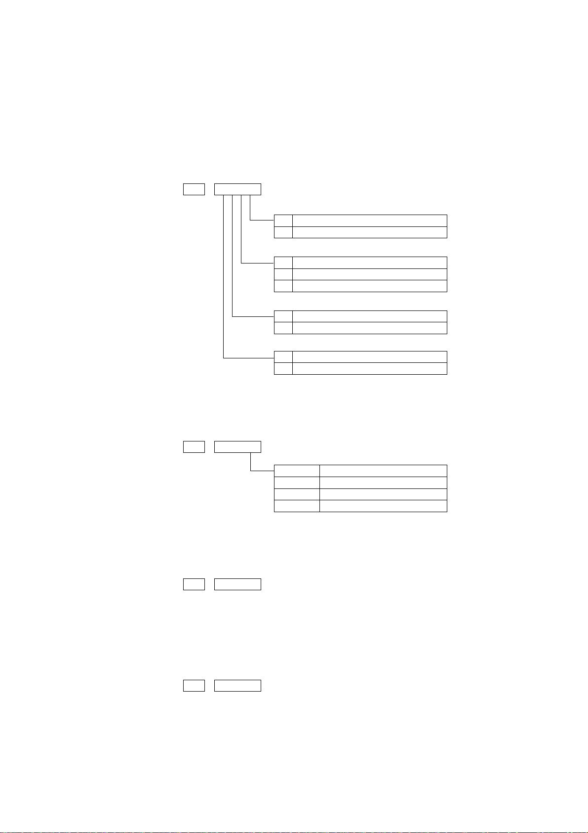
The parameter screen opens by pressing the MODE key for 2 seconds or longer.
Parameter screen
On the parameter screen, the left is displayed.
Press the MODE key several times to open the screen for the communications
2.1 Overview
Before communications is performed, initial settings must be made on this product. Enter such
settings with the keys on the front panel.
(No change can be made during communications.)
Measured
value
Proportional
band
Power-on
[MODE key]
[MODE key]
Initial screen Displayed for 4 seconds upon the power-on.
In 4 seconds from the power-on, the screen automatically opens.
type “###.”
(The number of the presses depends on specifications including options.)
Press the MODE key to open the following screens. Use the p and q keys
to make inputs.
Communications
type
Communications
parameter
Communications
speed
Communications
address
Response delay
time
Upon completion of the settings, press the MODE key for 2 seconds or longer; the screen returns to
the measured value screen.
The parameters shown above are initial values.
MODE key: Press the MODE key once to change a screen.
2.2 Setting a communications type
Press and set the first digit using the p and q keys. The initial setting is "###."
• When RS-485 is specified
Not used (off)
RS-485 (on)
• When RS-232C is specified
Not used (off)
RS-232C (on)
* This screen in not key-locked.
No switchover between RS-232C and RS-485 is possible. (Must be specified at the time of
purchase.)
4
Page 5
2.3 Setting a data length
F
Stop bit 1
I
Stop bit 2
c
No parity
f
Odd parity
D
Even parity
N
Data len
gth, 7 bits
E
Data length, 8 bits
˜
:
BCC check
c
BCC check disabled
j
BCC check enabled
12
00 BPS
2400 BPS
4800 BPS
9600 BPS
2.4 Setting a stop bit length
2.5 Setting a parity
2.6 Setting whether to conduct a BCC check
Operate the ▲ and ▼ keys to make the settings. The initial value is HHHH.
p: Stop bit length
¢: Parity
˜¿¢p
¿: Data length
2.7 Setting a communications speed
Operate the ▲ and ▼ keys to make the settings. The initial value is HH.
****
I
K
E
M
2.8 Setting an address
Operate the ▲ and ▼ keys to make the settings. The initial value is H.
Setting range: 1 to 99 stations (It cannot be set to a 0.)
2.9 Setting a response delay time
Set a time from the time when the high-level computer finished sending a "request message" until
the time when it delivers the line and enters an input state.
Operate the ▲ and ▼ keys to make the settings. The initial value is ###.
Setting range: 0 to 250msec
* If the response delay time is set to a short setting, the communications may not be conducted
normally.
* In a real operation, the processing time for this product will be added, in addition to the response
delay time.
5
Page 6
3. Communications control
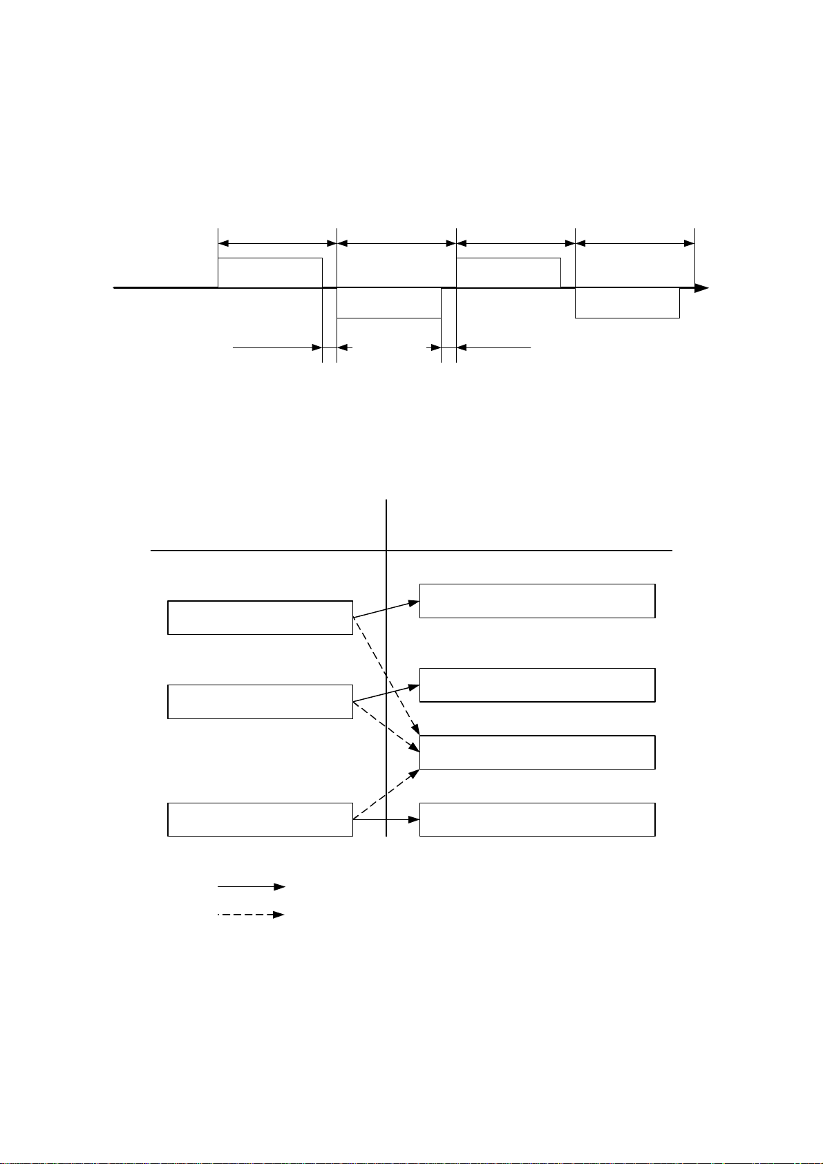
3.1 Communications procedure
This product returns a "response message" in response to a "request message" from a high-level
computer. It therefore does not initiate a transmission.
Transmitted by a high-
level computer
High-level computer
This product (TTM-10L)
See "2.9 Setting a response delay time."
See "3.6.1 Communications timing."
Request message
Response delay time
0-250ms
Transmitted by
TTM-10L
Response message
3.2 Message types
n Messages are roughly divided into the following types:
Request message (transmitted
from a high-level computer)
"3.3.1"
Read request message
Transmitted by a high-
level computer
Request message
1ms or more
See "3.6.2 Interval between requests."
Response message (transmitted
from this product)
"3.4.1"
Receipt acknowledgement and data
response
Transmitted by
TTM-10L
Response message
"3.4.2"
"3.3.2"
Write request message
"3.3.3"
Store request message
"3.4.3"
"3.4.2"
: Response when a normal "request message" is received
: When a received "request message" contains an error
Write complete response
Reception error and error description
response
Store complete response
n All codes (except for BCC) from STX and data to ETX are expressed in ASCII codes.
n In assembling a program for a high-level computer, see "7. Table of identifiers (codes)" and "8.
Table of ASCII codes" at the end of this manual.
6
Page 7

3.3 Composition of a request message (transmitted from a high-level
computer to this product)
n For codes ① to ⑩, see "3.5 Description of codes."
n For specific examples of request messages, see "4.1 Examples of communications to be read"
and "4.2 Examples of communications to be written."
3.3.1 Composition of a read request message
STX
□
①
②
Start code③Contents of the
Address
□
□
request: read/write
R
□
④
|
Identifier
3.3.2 Composition of a write request message
STX
□
①
②
Start code③Contents of the
Address
□
□
W
request: read/write
□
④
|
Identifier
□
□
|
ETX
BCC
□
|
⑥
⑦
End code
BCC data
□
□
□
□
⑤
Numerical data
BCC
ETX
⑥
⑦
End code
BCC data
3.3.3 Composition of a store request message
STX
□
□
S
T
W
②
①
Start code③Contents of the
request: read/write
Address
④
|
Identifier
7
ETX
R
|
⑥
End code
BCC
⑦
BCC data
Page 8

3.4 Composition of a response message (transmitted from this product to a
high-level computer)
n For codes ① to ⑩, see "3.5 Description of codes."
n For specific examples of request messages, see "4.1 Examples of communications to be read"
and "4.2 Examples of communications to be written."
3.4.1 Response message in response to a read request message
STX
ACK
□
□
□
□
□
□
□
□
□
BCC
ETX
□
①
②
Start code⑧Acknowledge code
Address
④
|
Identifier
|
⑤
Numerical data
⑥
⑦
End code
BCC data
3.4.2 Response message in response to a write/store request message
STX
□
□
①
②
Start code⑥End code
Acknowledge code
Address
ACK
⑧
BCC
ETX
⑦
BCC data
3.4.3 Response message in the case of an error
STX
NAK
□
□
BCC
ETX
□
①
②
Start code
acknowledge code
Address
⑨
⑩
End code
Negative
Error type
8
⑥
⑦
BCC data
Page 9

3.5 Description of codes
n The codes from ① STX, ② address to ⑩ ERR type as indicated below are expressed in
ASCII codes.
n For the ASCII codes, see "8. Table of ASCII codes."
n For conversion to ASCII codes, see "4. Examples of communications."
① STX
This code is needed for the receiver to detect the top of the message. It is affixed to the top
of a character string to be sent.
② Address
This is the address of the party (this product) with whom a high-level computer
communicates. The address in the response message from this product indicates the sender
of the response message.
③ Contents requested
Enter a code R or W.
R: to read data from this product
W: to write or store data in this product
④ Identifier
An identifier is a classification code (identifier) for data to be read or written and expressed
in a three-digit alphanumerical ASCII code. See "7. Table of identifiers (codes)."
⑤ Numerical data
These are data to be read or written, and are all expressed in five digits regardless of the
type.
Negative data: The "-" (minus) sign is in a single digit at the largest digit.
Position of the decimal point: 5-digit data does not include a decimal point.
Example: The table below indicates the significances of 5-digit numerical data 00010.
Example Significance of the value
Proportional band (P) →1.0%
Data (PV), etc, whose decimal point can be shifted
When the decimal point setting (DP) is 0 →10
When the decimal point setting (DP) is 0.1 →1.0
Even when "###" is set to "0" on a model with a platinum resistance temperature detector, a
communications data is transmitted with a decimal point.
⑥ ETX
This code is needed for the receiver to detect the end of a message. It is affixed to the end of
a character string to be sent (except for BCC).
⑦ BCC
This is a check code for error detection and is the exclusive OR (EX-OR) of all characters
from STX to ETX.
If the BCC check is set to "Disabled" in the communications settings in this product, this
code (BCC) will not be incorporated in the response message. See "2. Settings regarding
communications."
9
Page 10

⑧ ACK
It is an acknowledge code. If a message received by this product is error-free, this code will
be incorporated in the "response message" from this product and returned.
⑨ NAK
It is a negative acknowledge code. If a "request message" received by this product is
error-ridden, this code will be incorporated in the "response message" from this product and
returned.
If the "request message" received is error-ridden, the error contents (⑩ ERR type) will be
incorporated in the "response message" from this product, following NAK.
⑩ ERR type
If a "request message" received from this product is error-ridden, the error contents (either
of the numbers in the table below) will be incorporated in the "response message" from this
product, following "⑨ NAK."
The error number 0 is an instrument error (memory error or A/D conversion error). It will
be incorporated in the "response message" regardless of whether there is an error in the
"request message."
The error number 9 is an AT error. It will therefore be incorporated in the "response
message" regardless of whether there is an error in the "request message." Remove the
cause of the error immediately and start the AT again.
If there are two or more errors occurring at the same time, the largest error number will be
incorporated.
The table below indicates the error contents and classifications.
Error No.
0 Instrument error (memory error or A/D conversion error)
1 The numerical data deviated from the "range of settings designated specifically with setting
items."
2 The change of requested items is disabled or there are no items to be read.
3 An ASCII code other than the numerical data was specified in the field of numerical data.
An ASCII code other than "0" and "-" was specified in the field of codes.
4 Format error
5 BCC error
6 Overrun error
7 Framing error
8 Parity error
9 A PV error occurred during AT. Or AT will not end 3 hours later.
Error contents in the "request message" received by this product
10
Page 11

3.6 Communications precautions
3.6.1 Communications timing
Set a sufficient response delay time to make sure that this product is switched over from
transmission to reception with regard to a high-level computer in using RS-232C and RS-485.
See the figure in "3.1 Communications procedure" and "2.9 Setting a response delay time."
3.6.2 Interval between requests
In transmitting a series of "request messages" from a high-level computer, allow for an interval of
1msec or more from the reception of a "response message" from this product to a next
transmission.
3.6.3 Response conditions
This product will not return a "response message" unless it receives a "request message" containing
an STX and ETX (BCC).
If, therefore, the "request message" is error-ridden, this product will not return a "response
message" (error reply) containing a NAK and ERR unless the conditions mentioned above are met.
Therefore, the high-level computer transmits the necessary "request message" again if a "request
message" is sent to this product but the latter does not return a "response message" at the end of an
appropriate period.
The moment this product receives an STX, it clears all codes received before that.
3.6.4 Errors in address specification
This product will not respond to any "request message" that specifies an address other than that
specified for itself. If, therefore, the address portion of a "request message" is error-ridden, none of
the mobile units will return a "response message."
Therefore, the high-level computer transmits the necessary "request message" again if a "request
message" is sent to this product but the latter does not return a "response message" at the end of an
appropriate period.
The moment this product receives an STX, it clears all codes received before that.
3.6.5 Number of digits in data and the decimal position
See "3.5 Description of codes, ⑤ Numerical data."
3.6.6 Operation after receiving a store request message
This product starts to store data after correctly receiving a store request message from a high-level
computer.
This product only stores data different from the contents of the EEPROM (data that is changed).
The time (TW) required for storing data is within 500ms.
This product transmits a storage-complete reply (ACK) when the data is stored.
This product will not guarantee that the data is stored if this product is turned off during a storage
operation. Do not turn off this product for 500ms after transmitting a store request message.
3.6.7 Operation after turning on the power
This product will not perform communications (no response) for about 4 seconds after it is turned
on. Allow for a delay until communications is started after this product is turned on.
11
Page 12

3.6.8 Storing data other than a store request message
Store all parameters in the EEPROM in either of the three cases described below, even if no store
request message is received.
1) If a parameter is changed by key operation in the communications mode
2) If auto-tuning is started and stopped normally in the communications mode
3) If the communications mode is switched to the local mode
3.6.9 Changing the settings (SV or SV2) by communications during auto-tuning
If a change of the setting (SV or SV2) used in control is attempted through communications during
the auto-tuning, "NAK" and "2" are responded.
12
Page 13

4. Examples of communications
4.1 Examples of communications to be read
Example: Request message: This requests this product set at address 27 to read the PV.
(High-level computer)
In response to that,
Response message: This returns PV data (00777).
(This product)
Read request message (transmitted from the high-level computer)
STX
2
P
7
V
R
BCC
ETX
1
①
Response message (returned from this product)
STX
2
7
①
②
Code Code, data ASCII code, note 2)
① Start code STX 02H
② Address 27 32H 37H
③ Request contents R (Read) 52H
④ Identifier, note 1) PV1 50H 56H 31H
⑤ Numerical data 00777 30H 30H 37H 37H 37H
⑥ End code ETX 03H
⑦ BCC data request 61H
response 02H
⑧ Acknowledge code ACK 06H
Note 1): See "7. Table of identifiers (codes)."
Note 2): For the ASCII codes, see "8. Table of ASCII codes."
③
②
ACK
P
1
V
⑧
④
⑥
④
0
⑦
BCC
0
7
⑤
ETX
7
7
⑥
⑦
13
Page 14

4.2 Examples of communications to be written
Example: Request message: This requests this product set at address 03 to set "the A1F setting to
(High-level computer) 135" (write 135).
(Set the event 1 function to the following: Error alarm type to be PV
error alarm 1, alarm type to be deviation lower limit alarm 3 and
additional function to be alarm hold + standby sequence (5).)
In response to that,
Response message: This returns a notice that the request message has been received.
(This product)
*Check that it has been written by reading the data separately.
Write request message (transmitted from a high-level computer)
STX
A
0
3
W
①
②
③
F
1
0
0
0
1
④
⑤
BCC
ETX
1
⑥
⑦
Response message (returned from this product)
STX
0
①
Code Code, data ASCII code, note 2)
① Start code STX 02H
② Address 03 32H 33H
③ Request contents W (Write) 57H
④ Identifier, note 1) A2F 41H 33H 46H
⑤ Numerical data 00135 30H 30H 31H 33H 35H
⑥ End code ETX 03H
⑦ BCC data request 56H
response 04H
⑧ Acknowledge code ACK 06H
Note 1): See "7. Table of identifiers (codes)."
Note 2): For the ASCII codes, see "8. Table of ASCII codes."
ACK
BCC
ETX
3
②
⑥⑦⑧
14
Page 15

5. Specifications
5.1 Communications standard category
Compliant with RS-485 and RS-232C
5.2 Communications specifications
Communications
type
Communications
system
Interface system
Character
Information system Half duplex
Synchronization system Asynchronous
Transmission code ASCII code
Signal line 2-line type 3-line type (2 for transmission and
Communications speed 1,200, 2,400, 4,800 and 9,600 bps
Start bit length Fixed at 1 bit
Stop bit length Either 1 or 2 bit can be selected.
Data length Either 7 or 8 bit can be selected.
Parity No, odd or even number can be selected.
BCC check Yes or no can be selected.
Communications address 1 to 99
RS-485 RS-232C
Compliant with RS-485 Compliant with RS-232C Network
Up to 1 pair, 31 stations 1 pair, 1 station
reception, and SG)
15
Page 16

6. Connections
6.1 Connecting TTM-10L in RS-485
High-level computers (parent stations) TTM-10L (child stations)
TTM-10L (child stations)
TTM-10L (child stations)
Install an end of line resistor at both of the farthest devices in the parent station and the mobile unit.
For a resistance value, use one that matches the characteristic impedance of the cable. Provided that
the synthesis is set to at least 75Ω.
6.2 Connecting TTM-10L in RS-232C
High-level computers (parent stations) TTM-10L (child stations)
For actual use, the following connection is required inside the connector in the parent stations: CS
(transmission permission) and ER (data terminal ready), and RS (transmission request) and DR (data
set ready) and CD (reception carrier detection).
16
Page 17

7. Table of identifiers (codes)
¢ For the setting range, selection items, initial values, etc., see "Operation Manual- Standard
Version" separately attached.
a) Character number or symbol in the operation flow described in "Operation
Manual - Standard Version" (separate volume)
é b) Identifier: This code represents an item. Enter this code in the identifier field in the
message. The □ in the frame represents an SP (ASCII code: 20H).
c) Character: The character to be displayed on the screen of this product.
d) Name: Item name
e) R/W: This specifies which is possible: reading, writing, or both.
f) Description:
10
11
12
Identifier
a)
A
B
C
D
E
1
2
3
4
5
6
7
8
9
PV1
□SV
1L1
1H1
□AT
□P1
□I1
□D1
□T1
□C1
□IO
SLL
SLH
CNT
PVS
PBB
□CP
Character
Setting value (PV) R
Control setting value (SV) R/W Target value of control *1
EV lower limit setting R/W R/W the EV lower setting *3, *4
EV upper limit setting R/W R/W the EV upper setting *3, *5
AT start/release R/W
Proportional band R/W R/W the proportional band *1
Integral time R/W R/W the integral time *1, *2
Derivative time R/W R/W the derivative time *1, *2
Proportional cycle R/W R/W the proportional cycle *1, *2
Control sensitivity R/W R/W the control sensitivity *1, *6
Input/output type R/W R/W the input/output type *10
20: Current (4-20 mA)
SV limiter lower limit R/W R/W the SV limiter lower limit
SV limiter upper limit R/W R/W the SV limiter upper limit
Control type R/W R/W the control type *1
PV compensation R/W R/W the PV compensation
Manual reset R/W R/W the manual reset *1, *2
Off point position R/W R/W the off point position *1, *6
Name R/W Description
Use it as monitor for measurements (PV).
When overscale: HHHHH
When underscale: LLLLL
R/W the auto-tuning status *1, *2
At start: 00001
At release: 00000
When "00001" is received, the auto-tuning
starts; when the auto-tuning stops, the
indication becomes "00000."
0 0 0 0 0
Output type
Input type
Input type
00: K thermocouple
01: J thermocouple
02: E thermocouple
03: T thermocouple
04: R thermocouple
05: S thermocouple
06: N thermocouple
07: W5Re/W26Re
10: Pt100
11: JPt100
Output type
0: None
1: Relay contact output
2: SSR drive output
17
Page 18

Identifier
a)
13
14
15
16
17
18
19
20
21
*1 On a model without control, "NAK" and "2" are responded.
*2 When the control output is of an ON/OFF control, "NAK" and "2" are responded.
*3 On a model without EV, "NAK" and "2" are responded.
*4 When the alarm type for EV is not "lower limit alarm or upper/lower limit alarm," "NAK" and "2" are responded.
*5 When the alarm type for EV is not "upper limit alarm or upper/lower limit alarm," "NAK" and "2" are responded.
*6 When the control output is of a PID control, "NAK" and "2" are responded.
*7 A model without EV responds "NAK" and "2."
*8 A model of a thermocouple input responds "NAK" and "2."
*9 A model of current and voltage inputs responds "NAK" and "2."
*10 Only R for output type: The input type cannot be changed for over "----."
A1F
ALC
□DP
□CF
LOC
□CJ
PV2
OM1
STR
Character
EV function R/W R/W the EV function *7
EV sensitivity R/W R/W the EV sensitivity *7
Decimal point position R/W
Switchover between °C and °F R/W
Lock setting R/W
Cold junction compensation
temperature
With a decimal point for a
measured value (PV)
Output status monitor R
Data store W
Name R/W Description
0 0 0 0 0
Additional function
PV event output
PV error event output
Additional function
0: None
1: Event output hold
2: Standby sequence
3: Event output + standby sequence
PV event output
0: None
1: Deviation upper/lower limit event output
2: Deviation upper limit event output
3: Deviation lower limit event output
4: Deviation upper/lower limit range event
output
5. Absolute value upper/lower limit event
output
6: Absolute value upper limit event output
7: Absolute value lower limit event output
8: Absolute value upper/lower limit range
event output
PV error event output
0: None
1: PV error event output
R/W the decimal point position *8
0: 00000
0.0: 00001
0.00: 00002
R/W the switchover between °C and °F *9
°C: 00000
°F: 00001
R/W the lock setting
OFF: 00000
All lock: 00001
Parameter lock: 00002
Used as a monitor for the cold junction
R
compensation temperature.
Indication range: -20 to 80 °C
When overscale: HHHHH
When underscale: LLLLL
Used as a monitor for "with a decimal point for a
R
measured value (PV)"
Indication range: -199.9 to 999.9
When overscale: HHHHH
When underscale: LLLLL
0 0 0 0 0
Output status
EV status
1: ON
0: OFF
Stores a changed data.
18
Page 19

8. Table of ASCII codes
ASCII code 02H 03H 06H 15H
Use symbols STX ETX ACK NAK
ASCII code 30H 31H 32H 33H 34H 35H 36H 37H 38H 39H
Use numerical
characters
2DH 20H
ASCII code 41H 42H 43H 44H 45H 46H 47H 48H 49H 4AH
Use characters A B C D E F G H I J
4BH 4CH 4DH 4EH 4FH 50H 51H 52H 53H 55H
K L M N O P Q R S T
0 1 2 3 4 5 6 7 8 9
−
Minus
SP
Space
55H 56H 57H 58H 59H 5AH 20H
U V W X Y Z
SP
Space
TOHO ELECTRONICS INC.
Head office: 1-13-21, Tanashioda, Sagamihara Kanagawa 229-1125 Japan.
Phone: +81-42-777-3311 Fax: +81-42-777-3751
47‑9929
19
 Loading...