

Page 1

TOHO ELECTRONICS INC.
Multi-Channel Board Controller
Detailed Manual
Thank you very much for purchasing a Multi-Channel Board Controller.
The Multi-Channel Board Controller outputs control signals that match an input from
a thermocouple (a K/J thermocouple) or an input from a temperature input from a
resistance bulb (Pt100/JPt100) to a predetermined setting.
The product comes equipped with an RS-485 or an RS-232C for data
communications with a host computer.
For control output, the product is provided with up to eight open collector outputs,
along with event outputs consisting of 11 open collector outputs (eight temperature
alarm outputs, one heater wire break alarm, one SSR breakdown alarm, and one error
alarm), eight current detector inputs, and one voltage input.
Please read this detailed manual carefully and use this product correctly.
1
Page 2

Contents
1. Operating precautions..........................................................................................................3
2. Names and functions of the components ............................................................................. 4
2.1 Product diagram.........................................................................................................4
2.2 Names and functions ................................................................................................. 4
3. Installation ...........................................................................................................................5
3.1 How to install the product .........................................................................................5
3.2 Where to install the product....................................................................................... 5
3.3 Outside dimensions.................................................................................................... 6
4. Making the connections.......................................................................................................6
4.1 Terminal arrangement diagram.................................................................................. 6
4.2 Terminal arrangement................................................................................................ 7
4.3 Cautions on making the connections......................................................................... 9
5. Before conducting control....................................................................................................9
6. Table of identifiers (codes) .................................................................................................. 9
7. Function description .......................................................................................................... 16
7.1 Display range and set range of temperature input ...................................................16
7.2 Display range and set range of current detector input ............................................. 16
7.3 Voltage input............................................................................................................ 16
7.4 Control output.......................................................................................................... 16
7.5 Temperature alarm output ........................................................................................ 17
7.6 Heater wire break alarm output ............................................................................... 18
7.7 SSR breakdown alarm output.................................................................................. 18
7.8 Error alarm output ................................................................................................... 18
7.9 Communication ....................................................................................................... 18
8. Specifications and ratings ..................................................................................................32
8.1 General specifications.............................................................................................. 32
8.2 Ratings and performance......................................................................................... 32
9. Maintenance and inspection...............................................................................................33
2
Page 3
1. Operating precautions
When the product reaches you, please ensure that the product you have received is of the following
model which you ordered.
Model: TTM−00BT−①−R−②
① Input type.........................0: Thermocouple input
1: Resistance bulb input
② Communication type:.......M1: RS-485
M2: RS-232C
To allow you to use the product safely, this detailed manual uses the following symbols:
Warning:
Caution:
Mishandling despite this warning may result in the user's death, electric shock,
burn, or other risk.
Mishandling despite this caution may result in the user's minor injury or product
damage.
Warnings
• Erroneously wiring a meter will cause a breakdown, possibly resulting in a fire or other incident. After
making the connections, therefore, always ensure that the correct wiring has been made before
energizing the meter.
• Remodeling the product will cause a breakdown, possibly resulting in a fire or other incident. Therefore
do not under any circumstances do any such thing.
• Please make sure that the package for the product contains the following:
* Product proper: 1 unit
* Operation manual: 1 copy
Should you find anything missing or a wrong model or any other inconvenience, please
contact our Sales Department. The contact details are at the end of this manual.
• Please deliver this detailed manual to the user. Please store it with care.
• Unauthorized reproduction or copying of a part or a whole of this manual is prohibited.
• Specifications in this detailed manual are subject to change without notice.
• We may not be able to take responsibility for a nonconformity or trouble resulting from the user's
operation of the product.
3
Page 4
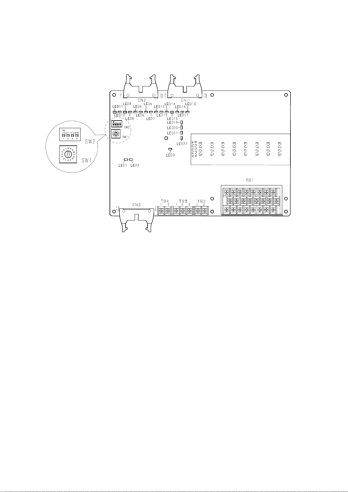
2. Names and functions of the components
2.1 Product diagram
Event output Control output
Voltage
Communi-
input
CT input
cation
Power
Temperature
input
2.2 Names and functions
2.2.1 SW1: Unit number change --- Change product unit numbers with the rotary switch.
Unit number: 0 to F (hexadecimal)
2.2.2 SW2: Communication speed change --- Change the communication speed with DIP
switches.
Communication speed setting: 4800/9600/19200/38400 bps
2.2.3 CN1: Control output connector
Connector: XG4A-1634 (Omron) or equivalent (eight open collector outputs)
2.2.4 CN2: Event output connector
Connector: XG4A-1634 (Omron) or equivalent (eleven open collector outputs)
2.2.5 CN3: CT input connector
Connector: XG4A-1634 (Omron) or equivalent (eight CT inputs)
2.2.6 TB1: Temperature input terminal
Sensor input terminal for thermocouple input or resistance bulb input
Thermocouple input: Two-level terminal block: ML-740-W1BF-16P (a Sato part)
or equivalent
Resistance bulb input: Three-level terminal block: ML-740-W3BF-24P (a Sato
part) or equivalent
2.2.7 TB2: Power terminal
Power voltage terminal (power voltage: 24V DC + 10% - 15%)
Through-type terminal block: ML-40-S1BYF-2P (a Sato part) or equivalent
2.2.8 TB3: Communication terminal
RS-485 or RS-232C communication terminal
Through-type terminal block: ML-40-S1BYF-3P (a Sato part) or equivalent
4
Page 5

2.2.9 TB4: Voltage input terminal
Voltage input terminal (input voltage range: 12 to 24V DC ±10%)
Through-type terminal block: ML-40-S1BYF-2P (a Sato part) or equivalent
2.2.10 LED1: Communication A RXD lamp (green)
2.2.11 LED2: Communication B TXD lamp (green)
2.2.12 LED3: Power lamp (green)
2.2.13 LED4 to 11: Temperature alarm output lamps (red)
2.2.14 LED12: Alarm output lamp for heater wire break (red)
2.2.15 LED13: Alarm output lamp for SSR breakdown (red)
2.2.16 LED14: Error alarm output lamp (red)
2.2.17 LED15 to 22: Control output lamps (orange)
Recommended socket for connector
MIL type socket (with strain relief): XG4M-1630-T (manufactured by Omron)
3. Installation
3.1 How to install the product
• See "3.3 Outside dimensions" and install the product with nine screws (φ3.5).
• Install the board as floated by at least 5mm with a spacer or something similar.
• Install it horizontally. Or install it vertically with its power supply facing upwards.
• When installing two or more products of this kind, install them at least 50mm apart.
• Connecting crimp terminals: Use crimp terminals of specified dimensions (M3, no more than
6.9mm wide).
• Connecting exposed wires: Use wiring of AWG22 to 16.
• Terminal screws: Tighten them to a specified torque (about 0.5N-m). A loose screw may cause a
fire or malfunction.
3.2 Where to install the product
Please install the product in either of the following places:
• Places where the temperature, humidity, and other conditions are within the operating
environmental ranges
• Places free of dust, greasy fumes, and other foreign matter
• Places protected as much as possible from mechanical vibration, impact, and other external forces
• Places as far as possible from devices using high-pressure ignition equipment
• Places away from high-voltage lines, welding machines, and sources of electric noises
• Places free of sulfide gases and corrosive gases
• Places protected from direct sunlight
• Places protected from water splashes
• Places protected as much as possible from electromagnetic effects
5
Page 6
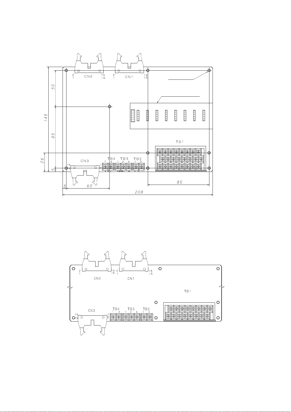
3.3 Outside dimensions
4. Making the connections
9-φ3.5 drill
Sub-board 36 × 114.5
Board height
• Thermocouple input
29.2mm maximum
• Resistance bulb input
39.1mm maximum
(from the bottom of the board
to the top of the part)
4.1 Terminal arrangement diagram
4.1.1 Thermocouple input
Event output
CT input
Voltage
input
Control output
Communi-
cation
Temperature input
Power
6
Page 7
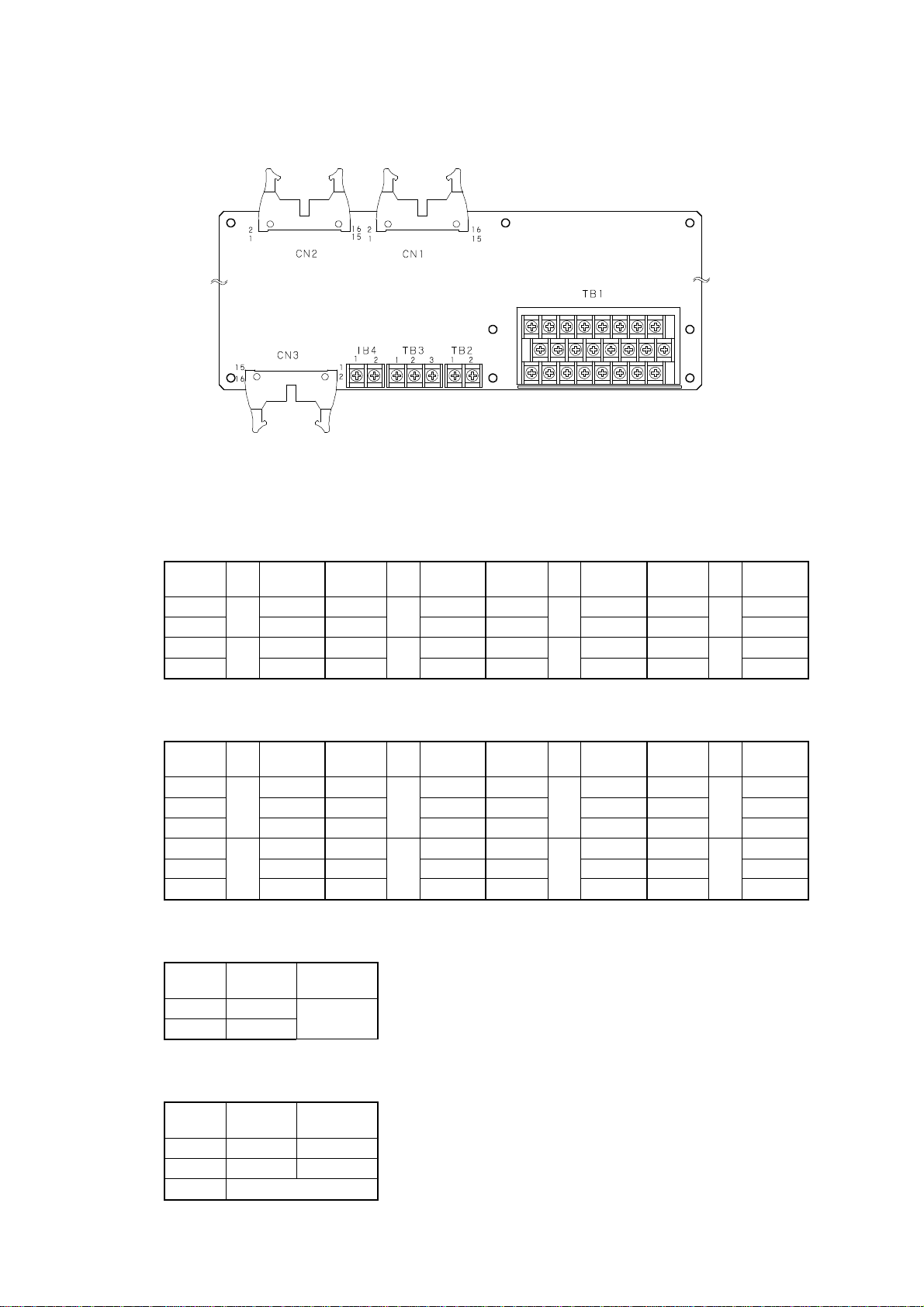
4.1.2 Resistance bulb input
Event output
CT input
Voltage
input
Control output
Communi-
cation
Temperature input
Power
4.2 Terminal arrangement
4.2.1 Temperature input (TB1: terminal block): For thermocouple input
* For terminal numbers, see the carvings in the terminals.
Terminal
No.
A1 + A3 + A5 + A7 +
B1
A2 + A4 + A6 + A8 +
B2
4.2.2 Temperature input (TB1): For resistance bulb input
Terminal
No.
A1 A A3 A A5 A A7 A
B1 B B3 B B5 B B7 B
C1
A2 A A4 A A6 A A8 A
B2 B B4 B B6 B B8 B
C2
4.2.3 Power (TB2: terminal block)
Terminal
No.
1 +
2 −
4.2.4 Communication (TB3: terminal block)
Terminal
No.
1 A RXD
2 B TXD
3 SG
CH
Terminal
name
Terminal
1
− B3
2
− B4
CH
Terminal
name
Terminal
1
b C3
2
b b4
Polarity
Power
voltage
24V
RS-485 RS-232C
No.
No.
CH
3
4
CH
3
4
Terminal
name
− B5
− B6
Terminal
name
b C5
b C6
Terminal
No.
Terminal
No.
CH
5
6
CH
5
6
Terminal
name
− B7
− B8
Terminal
name
b C7
b C8
Terminal
No.
Terminal
No.
CH
7
8
CH
7
8
Terminal
name
−
−
Terminal
name
b
b
7
Page 8

4.2.5 Voltage input (TB4: terminal block)
Terminal
No.
1 +
2 −
Polarity
4.2.6 Control output (CN1: connector)
Connector
No.
1 1 O.C
2 1 COM
3 2 O.C
4 2 COM
5 3 O.C
6 3 COM
7 4 O.C
8 4 COM
9 5 O.C
10 5 COM
11 6 O.C
12 6 COM
13 7 O.C
14 7 COM
15 8 O.C
16 8 COM
O.C.: open collector output
COM: common
CH
Terminal
name
4.2.7 Event output (CN2: connector) 4.2.8 CT input (CN3: connector)
Connector
No.
1 1 Temperature alarm 1 output O.C. 1 1
2 2 Temperature alarm 5 output O.C. 2 1
3 3 Temperature alarm 2 output O.C. 3 2
4 4 Temperature alarm 6 output O.C. 4 2
5 5 Temperature alarm 3 output O.C. 5 3
6 6 Temperature alarm 7 output O.C. 6 3
7 7 Temperature alarm 4 output O.C. 7 4
8 8 Temperature alarm 8 output O.C. 8 4
9 1 Temperature alarm 1 to 4 output COM 9 5
10 2 Temperature alarm 5 to 8 output COM 10 5
11 3 Alarm output O.C. for heater wire break 11 6
12 4 Alarm output COM for heater wire break 12 6
13 5 SSR breakdown alarm O.C. 13 7
14 6 SSR breakdown alarm COM 14 7
15 7 Error alarm O.C. 15 8
16 8 Error alarm COM 16 8
O.C.: open collector output
COM: common
CH Terminal name
Connector
No
CH
8
Page 9

4.3 Cautions on making the connections
configured to a "sensitivity" of 0.
point" to change the ON/OFF point without changing the
Warning
• Before making the connections, turn off this product. Otherwise you may get an electrical shock.
Warnings
• This product will not begin control for about 10 seconds after being turned on. (It will not activate its
outputs or other components.) Be careful if you wish to use the product as an interlocking circuit.
• Check the operation manual and other documents to ensure that you make the correct connections for
the temperature input terminal, power terminal, and other terminals.
• To connect a resistance bulb to this product, use wiring having a line resistance of no more than
5Ω per wire.
• To connect a thermocouple to this product, use a specified kind of compensating lead wire or
element wire.
• Use a shielded wire if you wish to use this product near a noise source. Do not wire an
input/output line in the same duct or conduit tube.
• Separate the input/output signal lines at least 50cm from the power line and load line.
5. Before conducting control
Selecting PID control Selecting ON/OFF control
This product is factory-configured to a "proportional
band" of 3.0. This product can conduct control in that
state. For better control, however, auto-tune (AT) this
product. AT automatically sets settings (values P, I, and
D) required for control. For AT, put this product into an
actual operating state (a state where the sensor input,
control output, and other components are wired). AT
takes some time.
This product is factoryIf conducting control causes the relay to flutter, increase
the sensitivity to reduce the flutter. If conducting
control causes this product to stabilize at a level lower
than the set temperature, increase the parameter "OFF
setting.
6. Table of identifiers (codes)
a) Identifier: A code that represents an item. Enter the code into the identifier field in the message.
(The code is a three-digit figure.) The □ in the frame represents SP (:space:ASCII code...20H).
b) Name: Item name
c) R/W: Specifies which function (read or write) is possible for an identifier into the current memory
bank, or whether both of those functions are possible.
r/w: Specifies which function (read or write) is possible for a memory bank other than the current
one, or whether both of these functions are possible. (This identifier can be read and written in a
memory bank.)
d) Description: Gives a description and specifies a set range and other details.
Note: For the R/W to a character not meeting the display conditions, this product responds with
"NAK2."
9
Page 10

Parameter
a) Identifier b) Name c) R/W d) Description and set range e) Remark
Initial value (communication
numerical data)
TC, thermocouple;
Pt, resistance bulb
SV1
00000
□CF
00000
INP
TC: 00000
Pt: 00010
PVG
00100
PVS
00000
PDF
00001
□DP
TC: 00000
Pt: 00001
□AT
00000
Setting R/W
Set a temperature unit R/W R/W of the °C/°F
Set an input type R/W R/W of the input type settings
Set a PV correction gain R/W
Set a PV correction zero
point
Set an input filter R/W R/W of the input filter setting
Set a decimal point R/W R/W of the decimal point setting
Start/release AT R/W R/W of the AT start/release
R/W of the control settings
r/w
Thermocouple input:
Thermocouple K, 0.0 to 1300.0°C
Thermocouple J, 0.0 to 800.0°C
Resistance bulb input: PT100/JPT, -199.9 to 500.0°C
°C: 00000
°F: 00001
Thermocouple input models:
Thermocouple K: 00000
Thermocouple J: 00001
Resistance bulb input models:
Pt100: 00010
JPt: 00011
R/W of the PV correction gain setting
r/w
Set range: 0.50 to 2.00 times
R/W
R/W of the PV correction zero setting
r/w
Set range: -199 to 999°C/-199.9 to 999.9°C
Set range: 0 to 99 seconds
No decimal point: 00000
Decimal point provided: 00001
Start: 00001
Release: 00000
Channel not specified
Neither the
thermocouple input nor
the resistance bulb
input can be changed.
Measurement
Gain correction
Measurement
Zero correction
The W is not possible
during ON/OFF
control.
10
Page 11
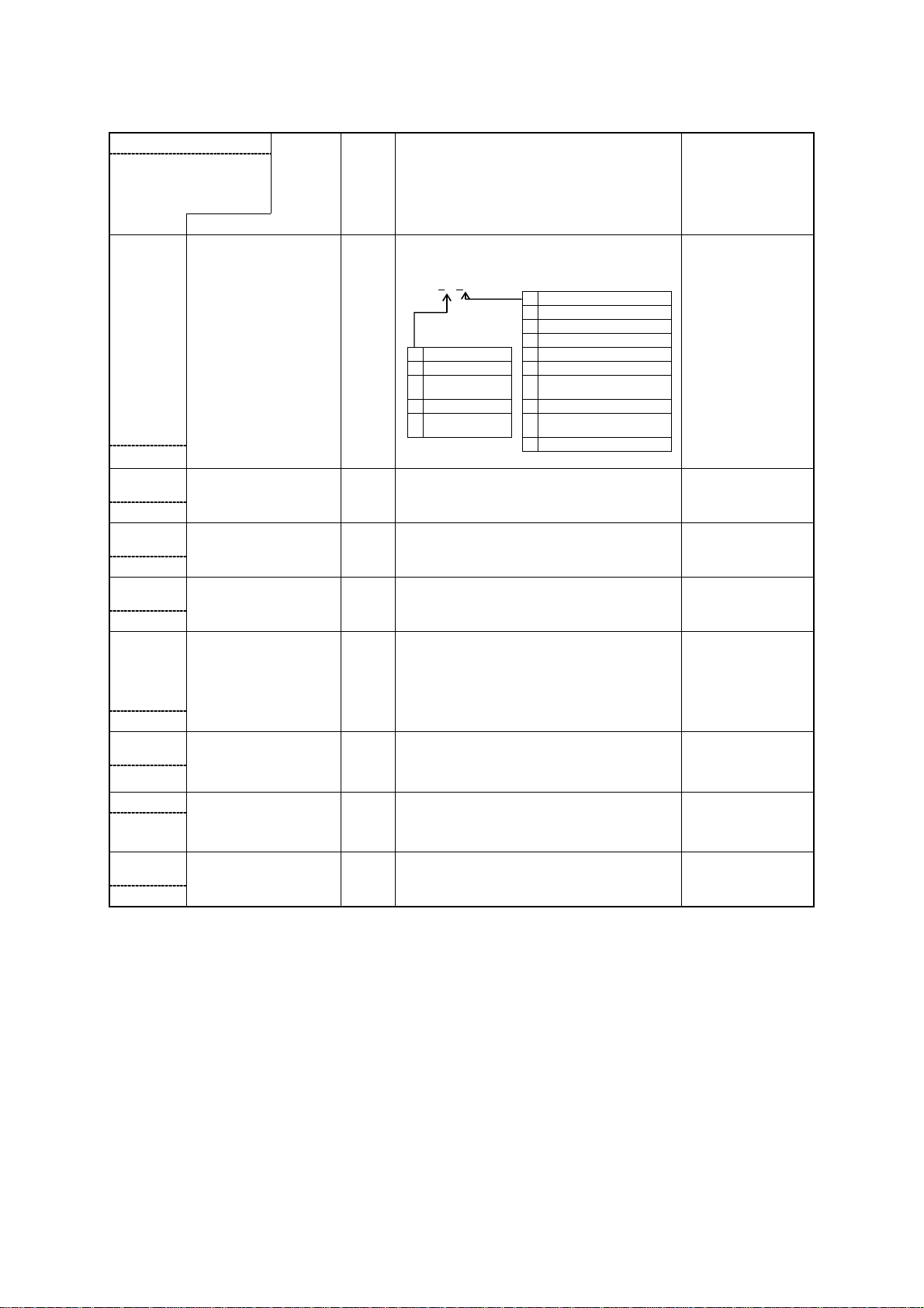
Event output parameters
0
1
2
3
4
5
6
7
8
a) Identifier b) Name c) R/W d) Description and set range e) Remark
Initial value (communication
numerical data)
TC, thermocouple;
Pt, resistance bulb
E * F
*: 1 to 8
00000
E * H
*: 1 to 8
00000
E * L
*: 1 to 8
00000
E * C
*: 1 to 8
00000
CTF
Temperature alarm
output*functional setting
R/W R/W of the temperature alarm output*functional
setting
000 * * PV temperature alarm functions
Additional functions
Type
0 None
1 Hold
2 Standby sequence
3 Hold + standby
sequence
Type
None
Deviation top/bottom limit alarm
Deviation top limit alarm
Deviation bottom limit alarm
Deviation range alarm
Absolute value top/bottom limit
alarm
Absolute value top limit alarm
Absolute value bottom limit
alarm
Absolute value range alarm
Set a temperature alarm
output*top limit
Set a temperature alarm
output*bottom limit
Set a temperature alarm
output*sensitivity
R/W
R/W of the temperature alarm output*top limit setting
r/w
Set range: -199 to1500°C/-199.9 to 1500.0°C
R/W
R/W of the temperature alarm output*bottom limit
setting
r/w
Set range: -199 to1500°C/-199.9 to 1500.0°C
R/W R/W of the temperature alarm output*sensitivity
setting
Set range: -199 to1500°C/-199.9 to 1500.0°C
CT function R/W R/W of the presence or lack of an alarm about heater
wire break and SSR breakdown
00000: None
00001: Heater wire break alarm function
00002: SSR breakdown alarm function
*1
*1
*1
*1
Heater wire break:
LED12
SSR breakdown:
LED13
00003: Heater wire break + SSR breakdown alarm
00000
C * I
*: 1 to 8
00000
ALB
00000
CT allocation channel R/W R/W of the status about the channel to which CT*(1 to
Error alarm function R/W R/W of the presence or lack of memory errors, A/D
function
Channel not specified
8) should be allocated
00000: None (not allocated)
00001 to 00008: (CH)
Error alarm: LED14
errors, and sensor error alarms
00000: None
00001: Present
CT*
*: 1 to 8
Set an output current error R/W R/W of the current of the heater current detector
Set range: 0.0 to 50.0A AC
Channel not specified
00000
11
Page 12

Voltage input parameters
a) Identifier b) Name c) R/W d) Description and set range e) Remark
Initial value (communication
numerical data)
TC, thermocouple;
Pt, resistance bulb
DIF
00000
SV2
00000
Set a voltage input function R/W
Setting 2 R/W
R/W of the voltage input function setting
Numerical
data
00000 None
00001 SV/SV2 function SV2
00002 RUN/READY function READY
00003 Auto/manual function Manual
00004 Forward/reverse operation
00005 Auto-tuning function AT start
00006 Forward operation
Function type
function
(SV2)/reverse operation
(SV) function
R/W of the control setting 2
r/w
Set range: SLL to SLH
When voltage is
applied
Forward
operation
Forward
operation (SV2)
Unit common parameters
a) Identifier b) Name c) R/W d) Description and set range e) Remark
Initial value (communication
numerical data)
TC, thermocouple;
Pt, resistance bulb
AWT
00000
MBK
00001
Response delay setting R/W R/W of the response delay setting
Set range: 0 to 250mS
Memory bank reading R/W Replaces the specified memory bank with the current
memory bank.
00001 to 00008 (example: memory bank 1 is 00001)
Channel not specified
No writing is possible
during AT.
12
Page 13

Monitor window parameters
a) Identifier b) Name c) R/W d) Description and set range e) Remark
PV1 Measurement R Used as a measurement monitor
CM*
*: 1 to 8
DIM DI monitor R R of the voltage input monitoring
OM1 Monitor the control output R R of the control output monitoring
EM1 Monitor the temperature
EM2 Monitor the temperature
ALM Monitor the alarm output R R of the alarm monitoring
CT measurement R R of the measured current of the heater current
alarm outputs 1 to 4
alarm outputs 5 to 8
When over-scale: HHHHH (the same is true when the
sensor has a wire break)
When under-scale: LLLLL
detector
When over-scale: HHHHH
When reading is impossible: -----
00000: State where voltage input is not applied
00001: State where voltage input is applied
000①②
① Output 1 state… 1:ON/0:OFF
② Output 2 state… 1:ON/0:OFF
R R of the temperature alarm output monitoring
0①②③④
①: temperature alarm output 4
②: temperature alarm output 3
③: temperature alarm output 2
④: temperature alarm output 1
R R of the temperature alarm output monitoring
0①②③④
①: temperature alarm output 8
②: temperature alarm output 7
③: temperature alarm output 6
④: temperature alarm output 5
00①②③
① Alarm output of heater wire break (1:ON/0:OFF)
② Alarm output of SSR breakdown (1:ON/0:OFF)
③ Error alarm output (1:ON/0:OFF)
When reading is
impossible: The CT
value cannot be read
unless the output of no
less than 190mS is
turned on.
*2
*3
*3
13
Page 14

Control parameters
a) Identifier b) Name c) R/W d) Description and set range e) Remark
Initial value (communication
numerical data)
TC, thermocouple;
Pt, resistance bulb
SLH
TC: 01200
Pt: 05000
SLL
TC: 0000
Pt: -1000
□MD
00001
CNT
00010
DIR
00000
MV1
00000
TUN
00002
ATG
00010
ATC
00020
□P1
00030
□I1
00000
□D1
00000
□T1
00020
ARW
01000
Set an SV limiter top limit R/W R/W of the SV limiter top limit setting
Set an SV limiter bottom
limit
Set the control mode R/W R/W of the control mode setting
Set a control type R/W R/W of the control type setting
Set a forward/reverse
operation switchover
Control output 1 operation
quantity
Set a tuning type R/W R/W of the tuning type setting
AT factor R/W R/W of the AT factor
AT sensitivity R/W R/W of the AT sensitivity
Set control output 1,
proportional band
Set an integral time R/W
Set a derivative time R/W
Set control output 1,
proportional period
Anti-reset windup R/W
From the bottom limit to the top limit of the set range
Provided that the difference from the SV limiter
bottom limit setting is no less than 50 digits.
R/W R/W of the SV limiter bottom limit setting
From the bottom limit to the top limit of the set range
Provided that the difference from the SV limiter top
limit setting is no less than 50 digits.
00000: Control stop (bottom limit output of the
operation quantity limiter)
00001: Control execution
00002: Manual control
00①②③
① Function
0 Type A
1 Type B (overshoot inhibition function)
② Output 1 control type
0 None
1 PID control
2 ON/OFF control
③ Output 2 control type (only during heating and
cooling control)
0 None
1 PID control
2 ON/OFF control
R/W R/W of the forward/reverse operation switchover
setting
00000: Reverse operation
00001: Forward operation
R/W R/W of the control output 1 operation quantity
Display range: 0.0 to 100.0%
Set range: ML1 to MH1
00001: Auto-tuning output 1
00002: Self-tuning output 1
00003: Auto-tuning output 2
00004: Self-tuning output 2
00005: Auto-tuning output 1/output 2
Set range: 0.1 to 10.0 times
Set range: 0 to 999°C/0.0 to 999.9°C
R/W
R/W of the control output 1, proportional band setting
r/w
Set range: 0.1 to 200.0%
R/W of the integral time setting
r/w
Set range: 0 to 3600 seconds
R/W of the derivative time setting
r/w
Set range: 0 to 3600 seconds
R/W
R/W of the control output 1, proportional period
r/w
setting
Set range: 1 to 120 seconds
R/W of the Anti-reset windup
r/w
Set range: 0.0 to 100.0%
For the range, see 7.1
on page 16.
For the range, see 7.1
on page 16.
Type A:
General and
conventional PID
control
Type B:
Our company's unique
PID control with
reduced overshoot
*4
14
Page 15

Control parameters
a) Identifier b) Name c) R/W d) Description and set range e) Remark
Initial value (communication
numerical data)
TC, thermocouple;
Pt, resistance bulb
MH1
01000
ML1
00000
□C1
00000
CP1
00000
MV2
00000
□P2
00020
□T2
00020
MH2
01000
ML2
00000
□C2
00000
CP2
00000
PBB
00000
□DB
00000
STR Save data W Save data
Set an operation quantity
limiter, top limit
Set an operation quantity
limiter, bottom limit
Set a control output 1,
control sensitivity
Control output 1
Set an OFF point
Control output 2 operation
quantity
Set control output 2,
proportional band
Set control output 2,
proportional period
Set an operation quantity
limiter, top limit
Set an operation quantity
limiter, bottom limit
Set a control output 2,
control sensitivity
Control output 2
Set an OFF point
Manual reset R/W
Set a dead band R/W
R/W
R/W of the operation quantity limiter, top limit setting
r/w
Set range: Operation quantity limiter, bottom limit
setting to 100.0%
R/W
R/W of the operation limiter, bottom limit setting
r/w
Set range: 0.0 to operation quantity limiter, top limit
setting
R/W
R/W of the control output 1, control sensitivity setting
r/w
Set range: 0 to 999°C/0.0 to 999.9°C
R/W
R/W of the OFF point setting of control output 1
r/w
Set range: -199 to 999°C/-199.9 to 999.9°C
R/W
R/W of the control output 2 operation quantity
r/w
Display range: 0.0 to 100.0%
Set range: ML1 to MH1
R/W
R/W of the control output 2, proportional band setting
r/w
Set range: 0.10 to 10.00 times
(Magnification for output 1, proportional band)
R/W
R/W of the control output 2, proportional period
r/w
setting
Set range: 1 to 120 seconds
R/W
R/W of the operation quantity limiter, top limit setting
r/w
Set range: Operation quantity limiter, bottom limit
setting to 100.0%
R/W
R/W of the operation limiter, bottom limit setting
r/w
Set range: 0.0 to operation quantity limiter, top limit
setting
R/W
R/W of the control output 2, control sensitivity setting
r/w
Set range: 0 to 999°C/0.0 to 999.9°C
R/W
R/W of the OFF point setting of control output 2
r/w
Set range: -199 to 999°C/-199.9 to 999.9°C
R/W of the manual reset
r/w
Set range: 0.0 to 100.0%
But -100.0 to +100.0% during heating/cooling control
R/W of the dead band
r/w
Set range: -100 to 100°C/-100.0 to 100.0°C
*1: If the control output 2 control type is ON/OFF control or PID control (if heating/cooling control is conducted), this product cannot be
used as a temperature alarm output.
*2: If the control output 2 control type is used as a temperature alarm output, the monitor for the control output of control output 2 is fixed at
0.
*3: If the control output 2 control type is used as ON/OFF control or as PID control, the temperature alarm output monitor is fixed at 0.
*4: If the control output 2 control type is set to "None": This product produces a temperature alarm output.
For ON/OFF control or PID control: This product performs heating/cooling control.
15
Page 16

7. Function description
7.1 Display range and set range of temperature input
7.1.1 Display range and set range of thermocouple input (JIS C 1602 - 1995)
Set range with a
decimal point
K (JIS) 0.0 to 1300.0°C -40.0 to 1326.0°C 0 to 1300°C -40 to 1326°C
J (JIS) 0.0 to 800.0°C -31.0 to 850.0°C 0 to 800°C -31 to 850°C
Display range with a
decimal point
Set range without a
decimal point
Display range without
a decimal point
7.1.2 Display range and set range of resistance bulb input (JIS C 1604 - 1997)
Set range with a
Pt100 (JIS)
JPt100 (JIS)
decimal point
-199.9 to 500.0°C -199.9 to 539.1°C -199 to 500°C -199 to 539°C
Display range with a
decimal point
Set range without a
decimal point
Display range without
a decimal point
7.2 Display range and set range of current detector input
7.2.1 Display range and set range: 0.0 to 50.0A AC
7.3 Voltage input
7.3.1 Voltage input: Entering a voltage (12 to 24V DC) from outside enables the selection of
functions from "7.3.2. Voltage input functions."
7.3.2 Voltage input functions
Function type When voltage is applied
None
SV/SV2 function SV2
RUN/READY function READY
Auto/manual function Manual
Forward/reverse operation function Forward operation
Auto-tuning function AT start
Forward operation (SV2)/reverse operation (SV) function Forward operation (SV2)
7.4 Control output
Control output is ensured by open collector output. Control operations can be selected from
heating control or heating/cooling control (types A and B). Setting the output 2 control type to
"ON/OFF control" or "PID control" activates heating/cooling control.
Note that heating/cooling control is fixed at control output on the side of heating output, and at
temperature alarm output on the side of cooling output. See the table below for the allocation of
control outputs and temperature alarm outputs for heating control and heating/cooling control.
Input
Control output
1CH
2CH
3CH
4CH
5CH
6CH
7CH
8CH
Heating control Heating/cooling control
Temperature alarm
output
1
2
3
4
5
6
7
8
1
2
3
4
5
6
7
8
Control output
1
2
3
4
5
6
7
8
Cooling output (temperature alarm output
is used as cooling output)
1
2
3
4
5
6
7
8
16
Page 17

7.5 Temperature alarm output
7.5.1 Temperature alarm output: Compare the measurements with the setting value of the
temperature alarm output and turn on and off the temperature alarm output.
• Operation table of temperature alarm outputs
1. Deviation top/bottom limit 5. Absolute value top/bottom limit
E*C
E*C
E*C E*C
E*L E*H
△
SV
0C (°F)
0℃(v)
E*L
E*H
2. Deviation top limit 6. Absolute value top limit
E*C
0℃(v)
0C (°F)
SV
△
E*H
3. Deviation bottom/limit 7. Absolute value bottom limit
E*C
E*L
△
SV
0℃(v)
0C (°F)
E*L
E*C
4. Deviation top/bottom limit range 8. Absolute value top/bottom limit range
E*L
E*C
E*H
E*C
E*L E*H
△
SV
E*C
0C (°F)
0℃(v)
Operation range of temperature alarm output: E*L, bottom limit setting of temperature alarm output; E*H, top
limit setting of temperature alarm output; E*C, temperature alarm sensitivity
7.5.2 Additional functions
• Standby sequence
This function inhibits temperature alarm output even if the conditions are met for temperature
alarm output when this product is turned on. Temperature alarm output is generated only when
this product deviates from the conditions for temperature alarm output and satisfies those
conditions again. This function is used for bottom temperature alarm output when this product
is turned on. This function is enabled when this product is turned on in the shaded portion in
the operation table of temperature alarm outputs.
[How to cancel this function]
This function is canceled when this product is activated or when either of the following setting is
changed: target, temperature alarm, PV correction, and temperature alarm setting.
• Temperature alarm output holding
When a temperature alarm output is generated, this function retains that state. Even if this
product deviates from the conditions for temperature alarm output, the temperature alarm output
will remain on.
[How to cancel this function]
To cancel this function, turn this product off and back on or disable the additional function for
temperature alarm output setting.
E*C
E*H
E*C
17
Page 18

7.6 Heater wire break alarm output
The output will be turned on if a heater wire break (no output even if the output is turned on)
remains for at least 190mS.
7.7 SSR breakdown alarm output
The output will be turned on if an SSR breakdown (there is output even if the output is off) remains
for at least 190mS.
7.8 Error alarm output
The output will be turned on in the case of a memory error, A/D error, or sensor error.
7.9 Communication
7.9.1 What can be done by communication
Communication allows you to read and write data in "Changing settings" and "Reading
information" and other items specified in "6. Table of identifiers."
However, reading and writing with ordinary commands are conducted on the RAM inside this
product. Turning this product off and back on will restore the written data back to what it was
before the writing (the values saved on the EEPROM).
To save written data on the EEPROM of this product, execute the data storage request message
(STR).
(See "7.9.10 Communication precautions.")
7.9.2 Pre-communication settings:
Before communication, this product must be set to initial settings for "setting a communication
speed" and "setting a unit number."
1) "Setting a communication speed": Set this value with DIP switches.
Use DIP switches 1 and 2. Always turn the 3 and 4 to OFF.
Following are the possible combinations.
DIP switch
1 2 3 4
OFF
ON
OFF
ON
Initial setting: 1: ON, 2 to 4: OFF (9600 bps)
OFF
OFF
ON
ON
Reserved Reserved
2) "Setting a unit number": Set this value with the rotary switch.
Set a unit number in a hexadecimal number (0 to F).
Initial setting: 0 (unit No. 00)
3) "Setting a response delay": Set a time to be taken from the time when a high-level computer
finishes transmitting a "request message" to the time when the line is delivered and this
product enters an input state.
• Set range: 0 to 250mS
• Initial value: 0mS
* Notes: An insufficient response delay may result in abnormal communication. Note also
that, in real operations, the processing time of this product will be added to the
response delay.
* Caution: Before "setting a communication speed" and "setting a unit number," always
turn off this product.
Communication
speed
4800 bps
9600 bps
192000 bps
384000 bps
18
Page 19

7.9.3 Communications procedure
This product returns a "response message" in response to a "request message" from a high-level
computer. It therefore does not initiate a transmission.
上位コンピュータが
上位コンピュータ本器要求メッセージ
応答遅延時間
0〜250ms 1ms以上
「2.8応答遅延時間の設定」参照
「3.7.1送受信タイミング」参照
7.9.4 Message types
n Messages are roughly divided into the following types:
Request message (transmitted
from a high-level computer)
"7.9.5 1)", "3.5.1"
Read request message
送信
本器が
送信
要求メッセージ
上位コンピュータが
送信
要求メッセージ
「3.7.2要求間隔」参照
Response message (transmitted
from this product)
"7.9.6 1)"
Receipt acknowledgement and data
response
本器が
送信
要求メッセージ
"7.9.6 2)"
"7.9.5 2)", "3.5.2"
Write request message
"7.9.5 3)"
Store request message
"7.9.6 3)"
"7.9.6 2)"
: Response when a normal "request message" is received
: When a received "request message" contains an error
Write complete response
Reception error and error description
response
Store complete response
n All codes (except for BCC) from STX and data to ETX are expressed in ASCII codes.
n In assembling a program for a high-level computer, see "6. Table of identifiers" and "7.9.13.
Table of ASCII codes" at the end of the book.
19
Page 20

7.9.5 Composition of a request message (transmitted from a high-level computer to
T X □ □ R □ □ □ E T X B C C
Contents of the
request: read
T X □ □ W □ □ □ □ □ □ □ □ E T X B C C
Contents of the
request: write
T X □ □ W S T R E T X B C C
Contents of the
request: write
this product)
n For codes ① to ⑧, see "7.9.9 Code description."
n For specific examples of request messages, see "7.9.11 Examples of communications to be
read" and "7.9.12 Examples of communications to be written."
1) Composition of a read request message
S
① ② ③ ④ ―⑤― ⑦ ⑧
Start code
Unit number
Channel
Identifier
End code
BCC data
2) Composition of a write request message
S
① ② ③ ④ ―⑤― ―――⑥――― ⑦ ⑧
Start code
Unit number
Channel
Identifier
Numerical data
End code
BCC data
3) Composition of a store request message
S
① ② ③ ④ ―⑤― ⑦ ⑧
Start code
Unit number
Channel
Identifier
End code
BCC data
20
Page 21

7.9.6 Composition of a response message (transmitted from this product to a
T X □ □ A C K □ □ □ □ □ □ □ □ E T X B C C
T X □ □ A C K E T X B C C
T X □ □ N A K □ E T X B C C
high-level computer)
n For codes ① to ⑪, see "7.9.9 Code description."
n For specific examples of request messages, see "7.9.11 Examples of communications to b e
read" and "7.9.12 Examples of communications to be written."
1) Response message in response to a read request message
S
① ② ③ ⑨ ―⑤― ―――⑥――― ⑦ ⑧
Start code
Unit number
Channel
Acknowledge code
Identifier
Numerical data
End code
BCC data
2) Response message in response to a write/store request message
S
① ② ③ ⑨ ⑦ ⑧
Start code
Unit number
Channel
Acknowledge code
End code
BCC data
3) Response message in the case of an error
S
① ② ③ ⑩ ⑪ ⑦ ⑧
Start code
Unit number
Channel
Error code
ERR type
End code
BCC data
21
Page 22

7.9.7 Composition of a memory bank function message
T X □ □ r □ □ □ □ E T X B C C
Contents of the
request: read
T X □ □ w □ □ □ □ □ □ □ □ □ E T X B C C
Contents of the
request: write
n For codes ① to ⑫, see "7.9.9 Code description."
n For specific examples of request messages, see "7.9.11 Examples of communications to be
read" and "7.9.12 Examples of communications to be written." Note that the request is in
lowercase characters.
1) Composition of a read request message
S
① ② ③ ④ ⑫ ―⑤― ⑦ ⑧
Start code
Unit number
Channel
Memory bank No.
Identifier
End code
BCC data
2) Composition of a write request message
S
① ② ③ ④ ⑫ ―⑤― ―――⑥――― ⑦ ⑧
Start code
Unit number
Channel
Memory bank No.
Identifier
Numerical data
End code
BCC data
22
Page 23

7.9.8 Setting and reading data collectively
T X □ A R □ □ □ E T X B C C
Contents of the
request: read
T X □ A W □ □ □ □ □ □ □ □ E T X B C C
Co
ntents of the
request: write
T X □ A W S T R E T X B C C
Contents of the
request: write
1) Composition of a read request message
a) All channels
S
① ② ③ ④ ―⑤― ⑦ ⑧
Start code
Unit number
Channel
Identifier
2) Composition of a write request message
a) All channels
S
① ② ③ ④ ―⑤― ―――⑥――― ⑦ ⑧
Start code
Unit number
Channel
Identifier
End code
BCC data
Numerical data
End code
BCC data
3) Composition of a store request message
a) All channels
S
① ② ③ ④ ―⑤― ⑦ ⑧
Start code
Unit number
Channel
Identifier
End code
BCC data
23
Page 24

7.9.9 Code description
n Codes from ① STX to ⑫ memory bank function are expressed in ASCII codes.
n For the ASCII codes, see "7.9.13. Table of ASCII codes."
n For the procedure for conversion to ASCII codes, see communication examples 7.9.11 and
7.9.12.
① STX
This code is necessary for the receiver to detect the top of a message. This is affixed to the
top of the character string to be transmitted.
② Unit number
This code is for a higher-level computer to identify the communication partner (this product).
Unit numbers are changed by using the rotary switch.
Set range: 0 to F (to be set in a hexadecimal number)
*Before changing a setting, always turn off this product.
③ Setting channels
This function is for setting channels for reading and writing data in this product.
Set range: 1 to 8 (each channel), A (all channels 1 to 8)
*Before changing a setting, always turn off this product.
④ Contents of requests
Enter either of the following codes: R, W, r, or w.
R (uppercase, 52H): For reading data from this product
W (uppercase, 57H): For writing data in this product or for saving data in this product
r (lowercase, 72H): For reading data from the memory bank of this product
w (lowercase, 77H): For writing data in the memory bank of this product or for saving data
⑤ Identifier
An identifier is a classification code (identifier) for data to be read or written and expressed in
a three-digit alphanumerical ASCII code. See "6. Table of identifiers."
⑥ Numerical data
These are data to be read or written, and are all expressed in five digits regardless of the type.
Negative data: The "-" (minus) sign is in a single digit at the largest digit.
Position of the decimal point: 5-digit data does not include a decimal point.
Example: The table below indicates the significances of 5-digit numerical data 00010.
Proportional band (P) →1.0%
Data (PV), etc, whose decimal point can be shifted
When the decimal point setting (DP) is 0 →10
When the decimal point setting (DP) is 0.1 →1.0
⑦ ETX
This code is needed for the receiver to detect the end of a message. It is affixed to the end of a
character string to be sent (except for BCC).
in this product
Example Significance of the value
24
Page 25

⑧ BCC
This is a check code for error detection and is the exclusive OR (EX-OR) of all characters from
STX to ETX.
⑨ ACK
It is an acknowledge code. If a message received by this product is error-free, this code will be
incorporated in the "response message" from this product and returned.
⑩ NAK
It is a negative acknowledge code. If a "request message" received by this product is
error-ridden, this code will be incorporated in the "response message" from this product and
returned.
If the "request message" received is error-ridden, the error contents (⑪ ERR type) will be
incorporated in the "response message" from this product, following NAK.
⑪ ERR type
If a "request message" received from this product is error-ridden, the error contents (either of
the numbers in the table below) will be incorporated in the "response message" from this
product, following "⑩ NAK."
The error number 0 is an instrument error (memory error or A/D conversion error). It will be
incorporated in the "response message" regardless of whether there is an error in the "request
message."
The error number 9 is an AT error. It will therefore be incorporated in the "response message"
regardless of whether there is an error in the "request message." Remove the cause of the error
immediately and start the AT again.
If there are two or more errors occurring at the same time, the largest error number will be
incorporated.
The table below indicates the error contents and classifications.
Error No.
0 Instrument error (memory error or A/D conversion error)
1 The num erical data deviated from the "range of settings designated specifically with setting
items."
2 The change of requested items is disabled or there are no items to be read.
3 An ASCII code other than numerical data was specified in the field of numerical data. An
ASCII code other than a numerical value or "-" was specified in the field of the highest digit.
4 Format error
5 BCC error
6 Overrun error
7 Framing error
8 Parity error
9 A PV error occurred during AT. Or AT will not end 3 hours later.
Error contents in the "request message" received by this product
⑫ Memory bank number
Up to eight sets per parameter that can be written in the memory bank can be stored in the
memory bank. This function is to specify which memory bank 1 to 8 is to be used for reading
or writing.
• Number of settings: Up to 8 sets
• Set range: 1 to 8
④ Reading and writing can be done in the memory bank only if the request is "r (lowercase,
72H)" or "w (lowercase, 77H)."
25
Page 26

7.9.10 Communications precautions
1) Communications timing
Set a sufficient response delay to make sure that this product is switched over from
transmission to reception with regard to a high-level computer in using communications.
See "7.9.3 Communications procedure" and "7.9.2 3) Setting a response delay."
2) Interval between requests
In transmitting a series of "request messages" from a high-level computer, allow for an interval
of 1msec or more from the reception of a "response message" from this product to a next
transmission.
3) Response conditions
This product will not return a "response message" unless it receives a "request message"
containing an STX and ETX (BCC).
If, therefore, the "request message" is error-ridden, this product will not return a "response
message" (error reply) containing a NAK and ERR unless the conditions mentioned above are
met.
Therefore, the high-level computer transmits the necessary "request message" again if a
"request message" is sent to this product but the latter does not return a "response message" at
the end of an appropriate period.
The moment this product receives an STX, it clears all codes received before that.
4) Errors in unit number specification
This product will not respond to any "request message" that specifies a unit number other than
that specified for itself. If, therefore, the a unit number portion of a "request message" is
error-ridden, none of the mobile units will return a "response message."
Therefore, the high-level computer transmits the necessary "request message" again if a
"request message" is sent to this product but the latter does not return a "response message" at
the end of an appropriate period.
The moment this product receives an STX, it clears all codes received before that.
5) Number of digits in data and the decimal position
See "7.9.9 Code description, ⑥ Numerical data."
6) Operation after receiving a store request message
This product starts to store data after correctly receiving a store request message from a
high-level computer.
This product only stores data different from the contents of the EEPROM (data that is
changed). The time (TW) required for storing data is within 2 seconds.
This product transmits a storage-complete reply (ACK) when the data is stored.
This product will not guarantee that the data is stored if this product is turned off during a
storage operation. Do not turn off this product for 2 seconds after transmitting a store request
message.
7) Operation after turning on the power
This product will not perform communications (no response) for about 3 to 5 seconds after it is
turned on. Allow for a delay until communications is started after this product is turned on.
26
Page 27

8) Storing data other than a store request message
T X A 4 R R V 1 E T X B C C
T X A 4 A C K P V 1 0 0 7 7 7 E T X B C C
Store all parameters in the EEPROM in either of the three cases described below, even if no
store request message is received.
If auto-tuning is started and ends normally. (Provided that only PID constants are saved.)
9) Changing the settings (SV or SV2) by communications during auto-tuning
Even if the settings (SV or SV2) used in control for auto-tuning are changed by
communications, the settings (SV or SV2) will not be changed until the auto-tuning ends.
Note also that memory banks cannot be changed either, during auto-tuning.
7.9.11 Examples of communications to be read
Example: Request message: Requests the reading of a PV value set in channel 4 of unit number 10.
(High-level computer)
In response to that,
Response message: This returns PV data (00777).
(This product)
Read request message (transmitted from the high-level computer)
S
① ② ③ ⑨ ―⑤― ⑦ ⑧
Response message (returned from this product)
S
① ② ③ ⑨ ―⑤― ―――⑥――― ⑦ ⑧
Code Code, data ASCII code, note 2)
① Start code STX 02H
② Unit number A (10) 41H
③ Channel setting 4 34H
④ Request contents R (Read) 52H
⑤ Identifier, note 1) PV1 50H 56H 31H
⑥ Numerical data 00777 30H 30H 37H 37H 37H
⑦ End code ETX 03H
⑧ BCC data request 11H
response 72H
⑨ Acknowledge code ACK 06H
Note 1): See "6. Table of identifiers."
Note 2): For the ASCII codes, see "7.9.13. Table of ASCII codes."
27
Page 28

7.9.12 Examples of communications to be written
T X 3 1 W E 1 F 0 0 0 1 1 E T X B C C
T X 3 1 A C K E T X B C C
Example: Request message: Requests that the temperature alarm output setting of EIF in channel 1
(High-level computer) of unit number 3 be changed to deviation top/bottom alarm + holding.
In response to that,
Response message: This returns a notice that the request message has been received.
(This product) *Check that it has been correctly written by reading the data separately.
Write request message (transmitted from a high-level computer)
S
① ② ③ ④ ―⑤― ―――⑥――― ⑦ ⑧
Response message (returned from this product)
S
① ② ③ ⑨ ⑦ ⑧
Code Code, data ASCII code, note 2)
① Start code STX 02H
② Unit number 3 33H
③ Channel number 1 31H
④ Request contents W (Write) 57H
⑤ Identifier, note 1) E1F 41H 34H 46H
⑥ Numerical data 00011 30H 30H 30H 31H 31H
⑦ End code ETX 03H
⑧ BCC data request 56H
response 05H
⑨ Acknowledge code ACK 06H
Note 1): See "6. Table of identifiers (codes)."
Note 2): For the ASCII codes, see "7.9.13. Table of ASCII codes."
28
Page 29

7.9.13 Table of ASCII codes
ASCII code 02H 03H 06H 15H
Code used STX ETX ACK NAK
ASCII code 30H 31H 32H 33H 34H 35H 36H 37H 38H 39H
Number used 0 1 2 3 4 5 6 7 8 9
2DH 20H
ASCII code 41H 42H 43H 44H 45H 46H 47H 48H 49H 4AH
Code used A B C D E F G H I J
ASCII code 4BH 4CH 4DH 4EH 4FH 50H 51H 52H 53H 54H
Alphabetical
character used
55H 56H 57H 58H 59H 5AH 20H 72H 77H
Y V W X Y Z
−
Minus
K L M N O P Q R S T
SP
Space
SP
Space
w
Lower case
r
Lower case
7.9.14 Communications specifications
1) Communications standard category: Compliant with EIA standard RS-232C or RS-485
2) Communications systems
: Network.................................. For RS-485: up to 1 pair, 16 stations
For RS-232C: 1 pair, 1 station
: Direction of information......... Half duplex
: Synchronization system..........Asynchronous
: Transmission code.................. ASCII code
3) Interface system
: Signal line............................... For RS-485: Two-wire type (two transmission and
reception lines)
For RS-232C: Three-wire type (two transmission and
reception lines, one SG line)
: Communications speed .......... 4,800, 9600, 19,200 and 38,400 bps
Set this with DIP switches.
: Communications distance ......For RS-485: 500 mm maximum
For RS-232C: 15 m maximum
Provided that it varies somewhat depending on the cable and other ambient conditions.
29
Page 30

4) Character
: Start bit length........................ Fixed at 1 bit
: Stop bit length........................Fixed at 2 bit
: Data length............................. Fixed at 8 bit
: Parity...................................... Fixed at no
: BCC check ............................. Fixed at yes
: Unit number ...........................0 to F (hexadecimal number)
Set this with the rotary switch.
5) Other functions: Memory bank function: This allows each parameter that can be written in the
memory bank to be saved in eight sets.
30
Page 31

7.9.15 Communication wiring
1) Connecting the RS-485 line
上位コンピュータ(親局) 本器(子局)
High-level computer (parent stations)
This product (mobile unit)
T/R(A)
T/R(B)
T/R(A)
T/R(B)
本器(子局)
This product (mobile unit)
T/R(A)
T/R(B)
本器(子局)
This product (mobile unit)
T/R(A)
T/R(B)
Install an end of line resistor at both of the farthest devices in the parent station and the mobile unit.
For a resistance value, use one that matches the characteristic impedance of the cable. Provided
that the synthesis is set to at least 75Ω.
2) Connecting the RS-232C
High-level computer (parent stations)
R
T
This product (mobile unit)
R
T
SG SG
In practice, it is necessary to connect the CS (transmission enable) and the ER (data terminal
ready), and connect the RS (transmission request) and DR (data set ready) and CD (reception
carrier detection) inside the connectors of the parent station.
31
Page 32

8. Specifications and ratings
8.1 General specifications
Power voltage 24V DC + 10% - 15%
Power consumption 8W or less
Insulation resistance Between inputs and outputs, 500V DC, 20MΩ or more
Withstand voltage Between inputs and outputs, 500V AC, 1 minute
Standard
environment
environment
Transportation/
storage
environment
Machine
specifications
Temperature/
humidity range
Power voltage 24V DC + 10% - 15%
Vibration condition 0G
Temperature/
humidity range
Power voltage 24V DC + 10% - 15%
Temperature/humidity
range
Vibration condition 0.5G (10 to 55Hz, 2 hours in each of the directions X, Y, and Z as installed on a
Impact condition 0 to 50G (directions X, Y, and Z as installed on a vertical panel, with no continuous
Package drop Drop height, 60cm (once each of the six sides, free fall without a rotary motion)
Weight Approx. 450g
8.2 Ratings and performance
23±10C° / 45 to 75%RH (non-condensing)
-10 to 55°C / 35 to 85%RH (non-condensing) Operating
-20 to 65°C / 20 to 90%RH (non-condensing, non-freezing)
vertical panel)
impact)
Temperature
input
Sampling period 200mS (at channel 8)
LED display LED type
Control
output/
temperature
alarm output
Voltage input
CT input ±5% of the full span
Input type
Output in a special state All outputs remain off for about 10 seconds after this product is turned on.
Open collector output Output rating: 24V DC, 100mA (maximum) per point
Input voltage range 12 to 24V DC ± 10%
ON-state voltage 10.8V (min)
ON-state current 4mA (min)
OFF-state voltage 4V (max)
Minimum input time 500mS or more
Thermocouple input K and J switchover (JIS C 1602-1995)
Resistance bulb input Pt100/JPt100 switchover (JIS C 1604-1997)
Power supply LED3 Goes on when this product is on (green)
Control output LED15 to 22 Goes on when the control output is turned on (red)
Temperature alarm
output
Heater wire break
alarm output
SSR breakdown alarm
output
Error alarm output LED14 Goes on (red) when there is a memory error, A/D error, or
Communication LED1
Input resistance: 1MΩ or more
Effect of external resistance: 0.4µV/Ω (0.01°C/Ω)
Burnout: Overdisplay
Measurement precision: Measurement ±(0.3% + 1 digit) or ±2°C, whichever
the larger
(to be specified under the standard environmental conditions, including the
cold contact compensation program)
External resistance: 0.2°C/Ω or less (per wire)
Burnout: Overdisplay
Bias current: approx. 2mA (flowing out of terminal A)
Measurement precision: Measurement ±(0.3% + 1 digit) or ±0.9°C,
whichever the larger
(to be specified under the standard environmental conditions)
LED4 to 11 Goes on when the temperature alarm output is turned on
LED12 Goes on (red) when there is a heater wire break (there is no
LED13 Goes on (red) when there is an SSR breakdown (there is
LED2
The control output is turned off when there is a measurement error.
(red)
output even if the output is turned on)
output even if the output is turned off)
sensor error
Blinks while receiving data (green)
Blinks while transmitting data (green)
32
Page 33

9. Maintenance and inspection
Symptom Check item
Inaccurate measurement Is the sensor normal? (Connect a different sensor to the line. Does it show a
similar symptom?)
Is the sensor correctly connected?
Is the correct sensor type set? (Is the sensor the same as the type setting
entered in the product?)
Are all the PV correction values set to the correct levels?
The setting does not match
the measurement.
Poor control Is the PID value correct? Perform auto-tuning again.
Abnormal output
(control/event output)
No communication occurs Are the switches SW1 and SW2 set to the correct unit number and
Does the heater have a sufficient capacity?
Is the integral time (I) set to the correct setting?
Is the output terminal correctly connected?
Is the control type set to the correct setting?
communication speed?
If you find any other question or doubt, contact our Sales Department.
33
Page 34

TOHO ELECTRONICS INC.
Head office: 1-13-21, Tanashioda, Sagamihara Kanagawa 229-1125 Japan.
Phone: +81-42-777-3311 Fax: +81-42-777-3751
47-9926
34
Page 35

35
 Loading...