

Page 1
2016/06/14
Solar Powered Wire less Signal
Torque Wrench System
BL series
Operation M anual
Tohnichi Mfg. Co. , Ltd.
Page 2

Page 3
Safety Symbol
Warning
Safety Precautions
To customers: Before using this product, please read this operating instruction carefully to use it
properly. If you have any question, please contact your nearest distributor or TOHNICHI MFG. CO.,
LTD. This operating instruction should be stored in a safe place.
This symbol is used for drawing attention to "safety precautions". If you see this
symbol in this operating instruction, attention should be paid to safety. Take
preventative actions according to the description and conduct "safety operations
and proper control".
Signal Words
The signal words are the headers which indicate the level of hazard that should be known for
human safety and in handling devices. The signal words for safety are "Danger", "Warning" and
"Caution" depending on the level of hazard to human. The signal words are used with the safety
symbol to indicate the following situations.
“ Danger" Indicates an imminently hazardous situation which, if not avoided, will result in
" Warning" Indicates a potentially hazardous situation which, if not avoided, could result
" Caution" Indicates a potentially hazardous situation which, if not avoided, may result in
The receiver can be operated only with the power voltage of DC18V to 36V specified in this
operating instruction.
Do not drop water or oil on this instrument. Do not use this instrument in an atmosphere of
flammable gas and steam. Use in such an atmosphere may result in fire.
Avoid shock or vibration to this instrument. It may cause a damage or failure.
Before use, make a pre-operation inspection and check the settings.
Be sure to conduct a periodic inspection of torque wrenches.
Use a torque wrench within the measurement range specified in the operating instruction.
Disconnect from power supply if the product needs to be stored for a long period of time.
Avoid using the instrument in a place where there are metal structures around it.
Avoid using the instrument near welding machines, electric discharge machines or machines
producing electromagnetic noise such as PC.
Before wiring, check power supply off.
Contact your nearest distributor or Tohnichi if any trouble.
death or serious injury.
in death or serious injury.
minor or moderate injury.
1
Page 4

INDEX
1 Outline 4
2 Feature 4
3 Components 4
4 Specifications 5
5 External View
5-1 BLE, European and China model 6
5-2 BLA, US model 7
5-3 BL, Japan model 8
5-4 Receiver Display and RS232C 9
5-5 Input and Output terminal 10
6 Preparation for Use
6-1 Solar Cell 11
6-2 Receiver 12
6-3 Antenna 15
6-4 Error on BL receiver 15
6-5 RS232C 16
7 Setting Receiver
7-1 Setting Procedure 17
7-2 Setting Procedure 18
8 Mounting Method of BL transmitter onto LS torque wrench 21
9 Trouble 23
10 Optional Item 23
11 Regulations 24
2
Page 5
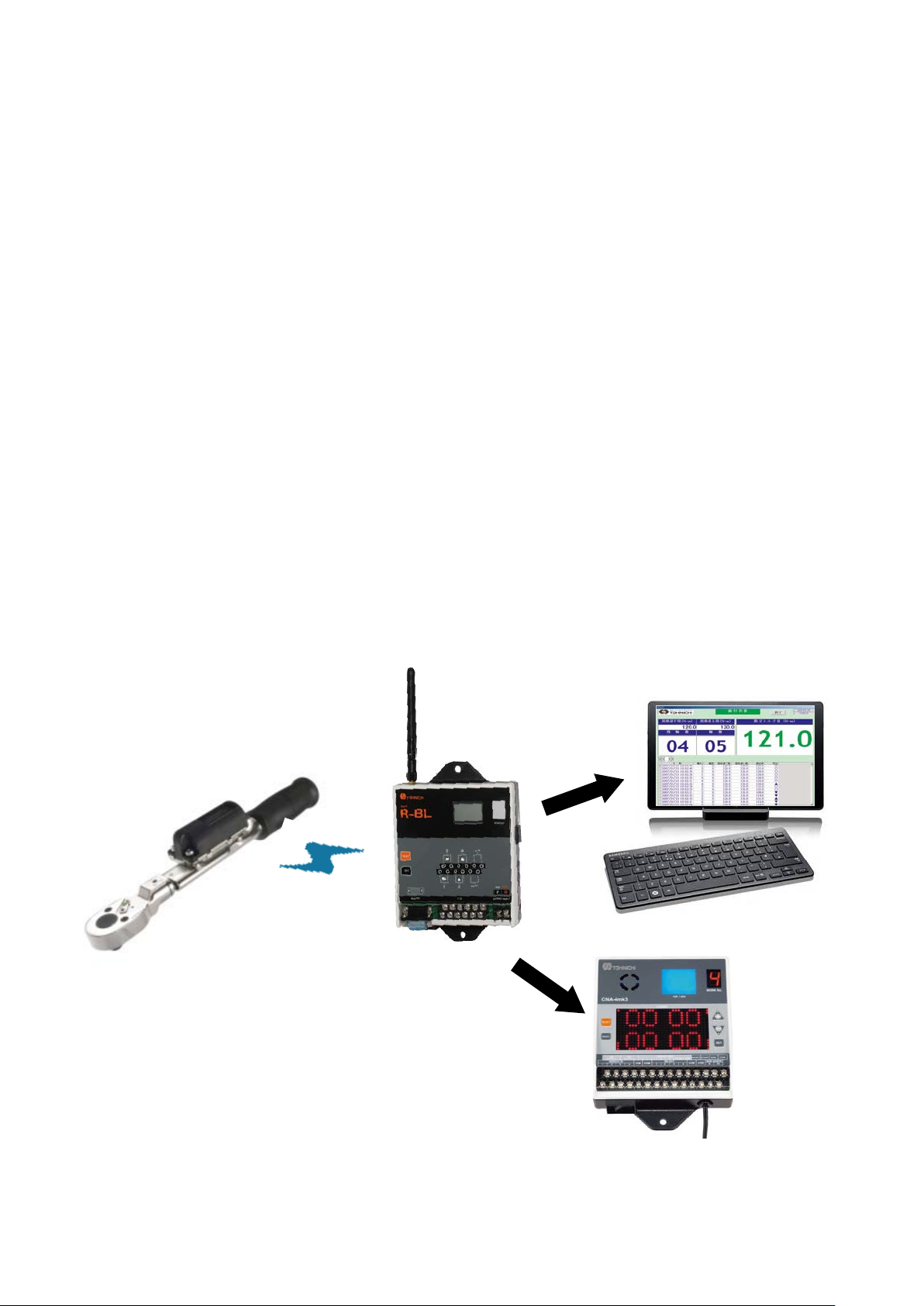
Wireless
PC / PLC
・
RS232C
・
Up to 10 torque wrench
1 Outline
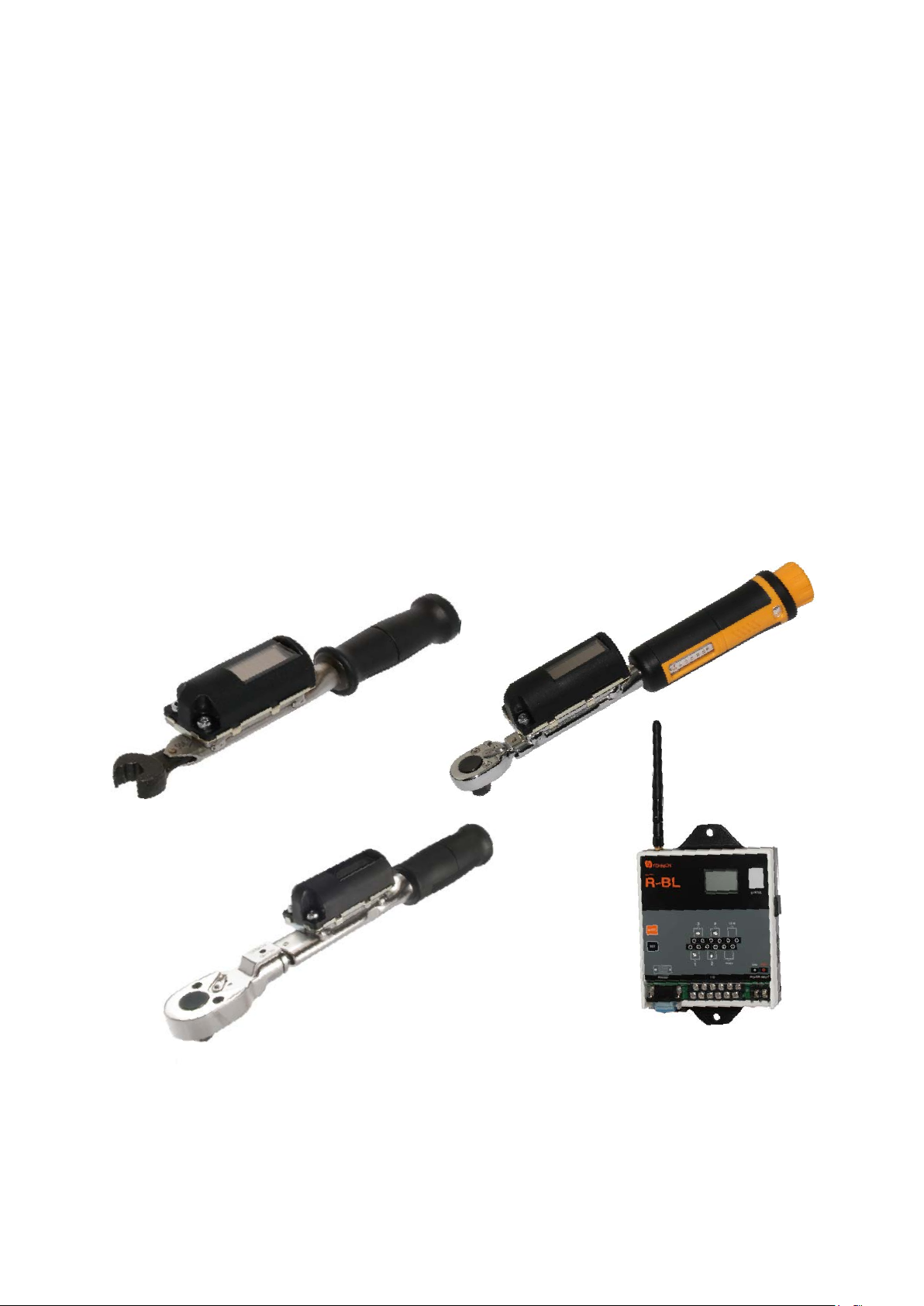
Tohnichi BL series torque wrenches send tightening completion signals by radio waves. The Solar
Panel eliminates need for battery maintenance and costs associated. R-BL receiver models capture
signals from BL wrenches and transfer to external equipment, such as a count checker CNA-4mk3,
Poka-Patrol. The receiver can transfer Completion signals and transmitter serial number to external
equipment. Miss-tightening prevention system can be established with PC or PLC.
2 Feature
• World’s first solar power transmitter
• Create up to 4 contact-free outputs in one receiver
• DC24V power source
• Available AC100V - 240V with optional BA-8 AC adapter
• Upgrading LS type torque wrench to BL type is possible
• Quick communication setting with one click
3 Components
Receiver
Wired
Wired
Option
ID/8-digit
3
Page 6
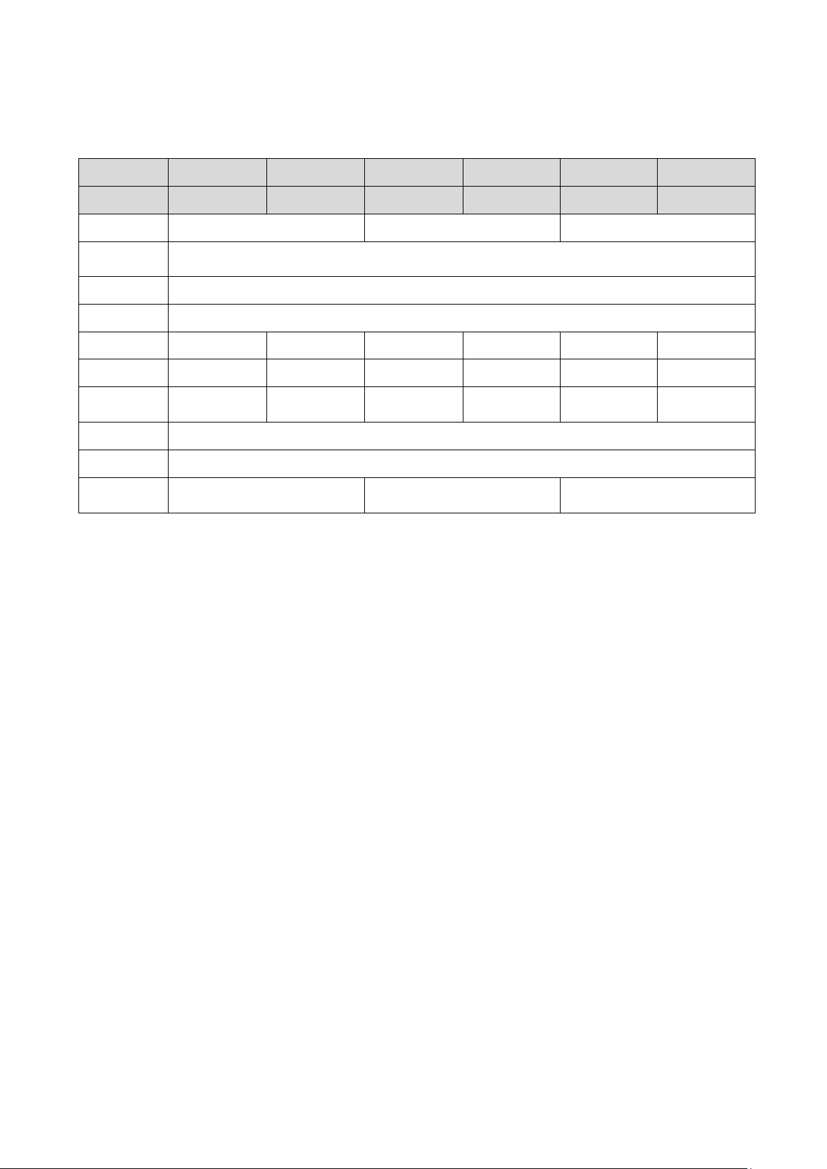
4 Specifications
Model
Description
Frequency
Modulation
System
Rate
ID
Power
Antenna Helix Antenna
Temperature
Distance
Wireless
Certificate
T-BLE R-BLE T-BLA R-BLA T-BL R-BL
Transmitter Receiver Transmitter Receiver Transmitter Receiver
868.3Mhz 902.875Mhz 928.35Mhz
FSK
125kbps
Fixed 8 digit
LED Light #1 LED Li ght #1 #1
Solar Cell DC24V #2 Solar Cell DC24V #2 Solar Cell DC24V #2
Dipole
Antenna
EU, China USA, Cana da Japan
Whip Antenna
0 – 40 degree Celsius
10 – 20 m, 30 – 60 feet #3
Dipole
Antenna
Helix Antenna
#1 4 Contact Signal Outputs and 6 RS232C Outputs, LAN Output by Request
Dipole
Antenna
#2 Connected directly to DC18-36V or with Optional, AC Adapter BA-8, 100 – 240V
#3 Radio frequency communication errors may be caused by electronic noise or a shield placed
between the transmitter and receiver. In addition, radio waves reflected by metal, concrete,
etc. may interfere with radio waves directly sent to the antenna of the receiver and dead
point occurs, resulting in communications errors.
4
Page 7
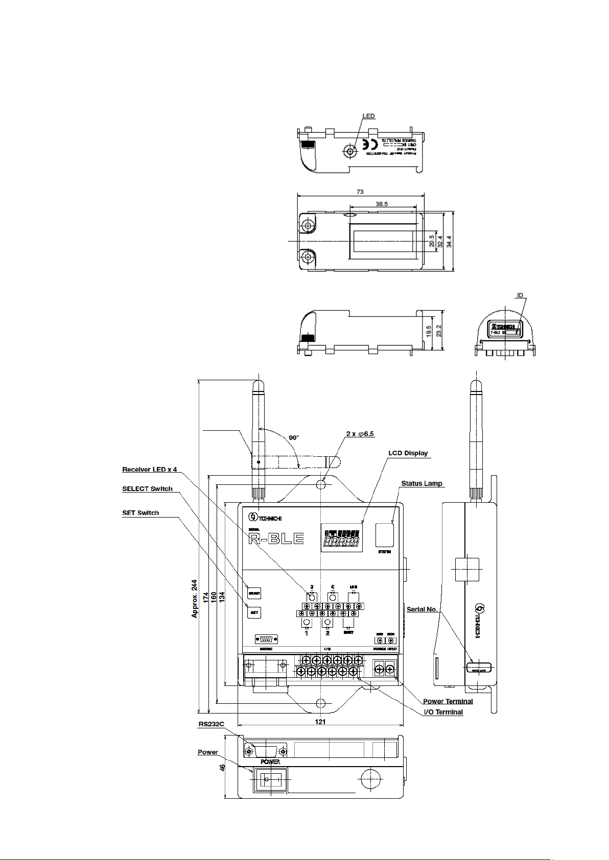
5 External View and Each Part Name
5-1 BLE, European and China model
5
Page 8
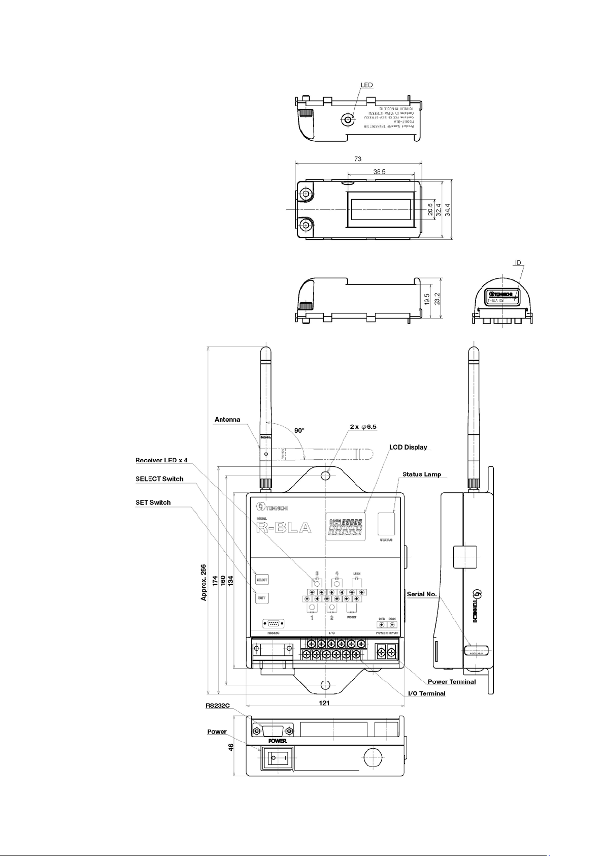
5-2 BLA, US model
6
Page 9
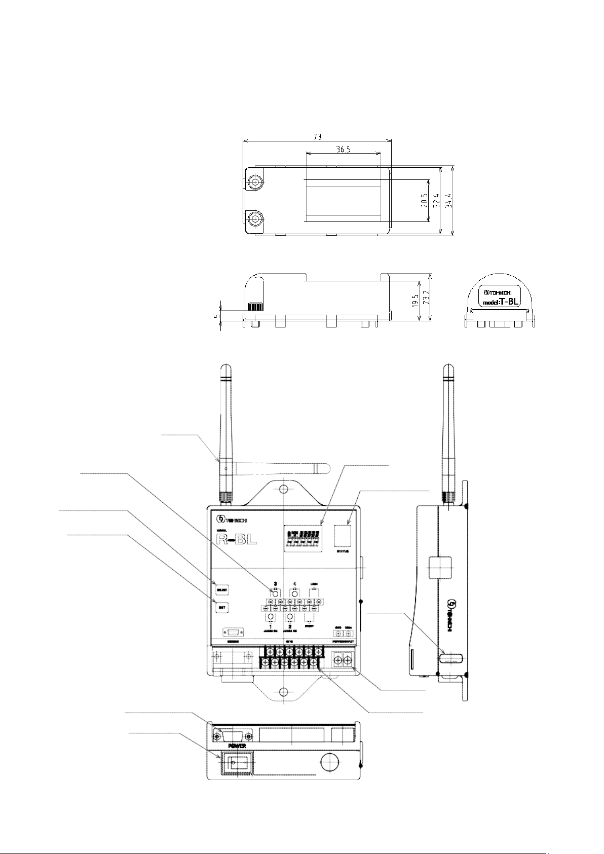
5-3 BL, Japan model
7
Page 10
3
RXD
Received Data Signal
4
5
GND
Ground
9
R-BL
PC/PLC D-Sub9S
Pin #
Signal
Description
Pin #
Signal
Description
1
DCD
2
TXD
TXD
3
RXD
3
RXD
4
4
DTR
5
GND
5
GND
6
6
DSR
7
CTS
7
CTS
8
RTS
8
RTS
9
9
NC
Frame
Shield
Frame
Shield
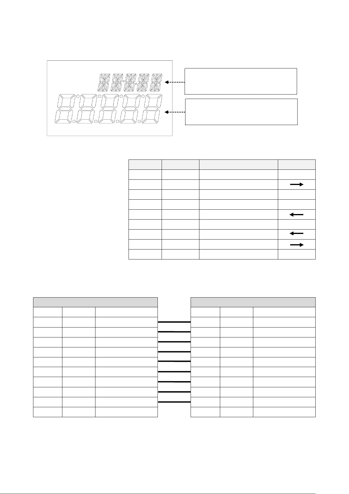
5-4 Receiver Display and RS232C
Indicating “ID”
Preference on mode setting
Indicating ID # when received signal
Status on mode setting
RS232C Pin Assignment
Pin Number Signal Description Direction
1
2 TXD Transmitted Data Signal
6
7 CTS Clear to Send Signal
8 RTS Request to Send Signal
R-BL to PC/PLC
Transmitted Data Signal
Received Data Signal
Ground
Clear to Send Signal
Request to Send Signal
1
2
N/A
Transmitted Data Signal
Received Data Signal
N/A
Ground
N/A
Clear to Send Signal
Request to Send Signal
N/A
8
Page 11
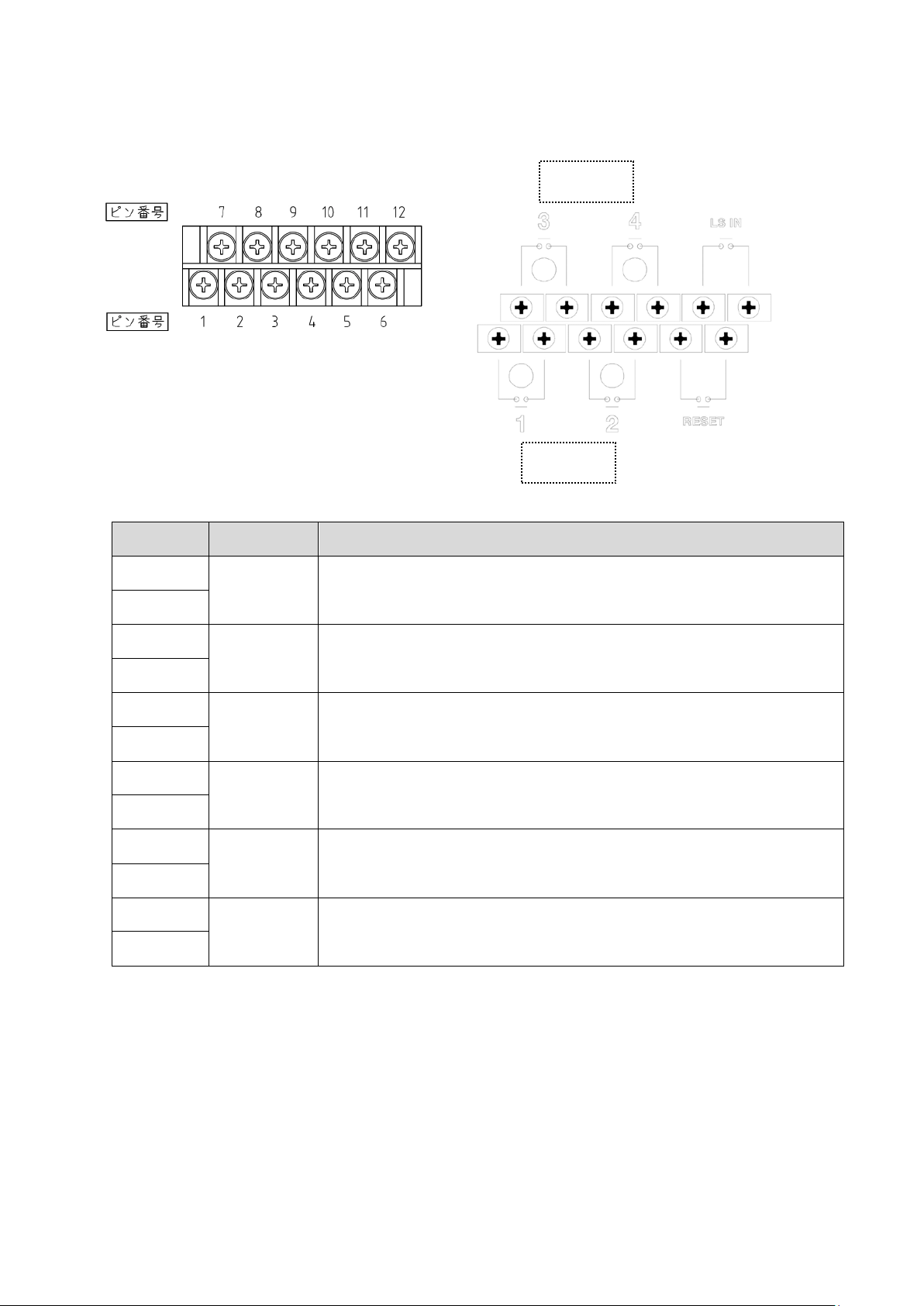
5-5 Input / Output Receiver
Terminal Block
Terminal # Description Features
1
OUT1
2
Outpu t no n-voltage contact signal and LED1 is lit When receiving
completion signal from BL transmitter #1. There is no polarity.
LED light
LED light
3
OUT2
4
5
RESET
6
7
OUT3
8
9
OUT4
10
11
LS IN
12
Outpu t no n-voltage contact signal and LED2 is lit When receiving
completion signal from BL transmitter #2. There is no polarity.
Contact terminal to reset “outputting non-vo lta ge conta ct s ignal”
and “auto-reset”. Required to input pulse, more than 0.1 second.
Outpu t no n-voltage contact signal and LED3 is lit When receiving
completion signal from BL transmitter #3. There is no polarity.
Outpu t no n-voltage contact signal and LED4 is lit When receiving
completion signal from BL transmitter #4. There is no polarity.
When BL torque wrench is down, LS torque wrench can be wired
to LS-IN and COM f or b ack-up.
9
Page 12
6 Precautions for Use
6-1 Solar Cell
Charge the battery before first use and after long periods of nonuse.
BL has available 3000 uses within 8 hours under 500 lux illuminance and 9.6 sec.
communication cycle.
BL can perform 300 uses on a full charge under 0 lux illuminance, No Light Conditions.
A fully charged battery will lose power after approx. 4 days if under no light conditions, 0 lux.
It is recommended to have sufficient light on the line/station to continually recharge the
internal battery cell.
There is no battery level indicator.
Keep the solar panel clean. A dirty panel decreases power generation efficiency.
Do not use a solvent such as paint thinner when you clean up the solar panel.
Recharge to full within 1 and half years even if you do not use BL to prevent the battery from
dying.
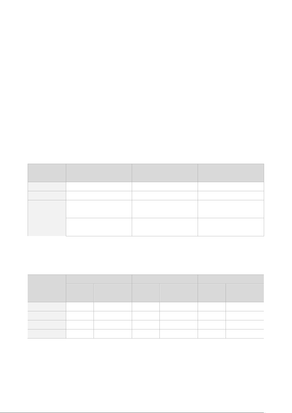
Table 1. Measure of the solar cell cha r ging time
Illuminance
lux
200 - Approx. 3 min. Approx. 144 hours
500 Standard factory Approx. 1.5 min. Approx. 72 hours
1000
2000
of fluorescent light, 30W
of fluorescent light, 30W
Activity
Under 60 to 70 cm
Under 40 cm
Charging time
Charging time for fully charge
for available one use
Approx. 44 sec. Approx. 35 hours
Approx. 22 sec. Approx. 17 hours
1 Above table is an estimate only. It is when BL is being charged under continuous light conditions.
2 BL charges as you are using it, therefore it is not a requirement for to have a fully charged battery
before use.
Table 2. Measure of illuminance by the available uses
Illuminance
lux
200 1500 19.2 1594 18.1 1688 17.1
No pre-charge 30 min. pre-charge 1 hour pre-charge
Available
Uses
Communication
Cycle /s
Available
Uses
Communication
Cycle/s
Available
Uses
Communication
Cycle/s
500 3000 9.6 3188 9.0 3375 8.5
1000 6140 4.7 6524 4.4 6908 4.2
2000 12278 2.3 13045 2.2 13813 2.1
3 Available uses means when BLA is charged under continuous light under each level of illuminance, lux.
4 "No pre-charge" not include the time of available one use on Table 1.
5 "Communication cycle" means 8 hours, 28,800 sec. divided by available uses.
10
Page 13
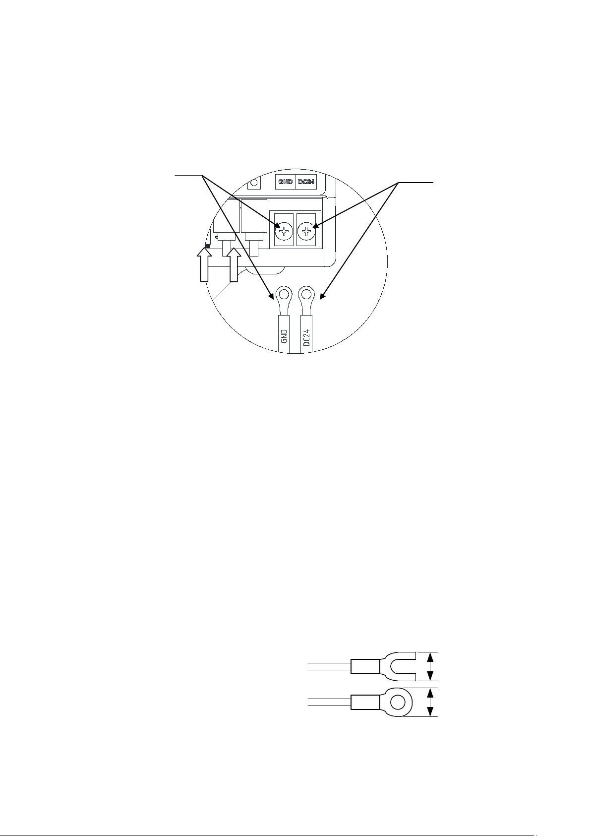
5.8
mm or less
5.8mm or less
GND
DC24V
6-2 R-BL, Receiver
a Power Source
Use the Receiver R-BLA within the range of DC24V.
Make sure to connect DC24V and GND to respective terminal.
The tightening torque of the terminal block is T=50cN.m.
R-BL, Receiver
b Operating environment
Use the device in an environment where no metal structure exits nearby wherever possible.
Do not set the antenna for the receiver close to any metal pole, wire or iron pipe. The BL
receiver antenna is arranged parallel to pipes, the communication status may be worsened.
Do not use the device around welding machines, electric discharge machines or any machine
producing electromagnetic noise such as PC.
c Connection with other equipment
Before wiring, check that the power of the device to be connected with the receiver is in the
OFF position.
Use a solder-less terminal of the size as shown below.
The tightening torque of the terminal block screw is T=50cN.m.
11
Page 14
EMI filter
EMI filter
Internal circuit
RESET
Vcc
LS-IN
Photocouple
r
Photocoupler
Non-voltage
contact switch
Non-voltage
contact switch
Relay
Relay
Internal circuit
OUT
1
OUT
4
Load
External power
Load
External power
・・・・
Resistive Load
1 time as large as the steady-state current
Solenoid Load
10 to 20 times as large as the steady-state current
Motor Load
5 to 10 times as large as the steady-state current
10 to 15 times as large as the steady-state current
About 3 times as large as the steady-state current
1 to 3 times as large as the steady-state current
Capacitor Load
20 to 40 times as large as the steady-state current
Trans Load
5 to 15 times as large as the steady-state current
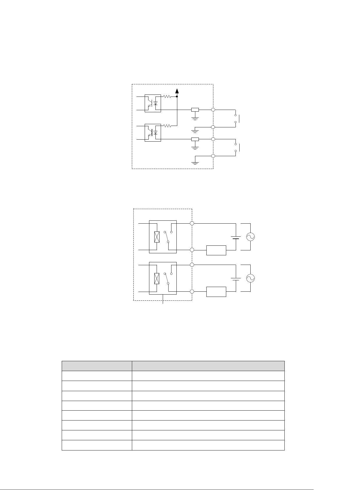
d Connecting “RESET” and “LS IN”
If you would like to connect to the "RESET" and "LS IN" terminal please use a non-contact
voltage switch. Example, LS torque wrench, relay, etc.
Do not feed the external power to input circuit to prevent damage.
e Relay output from OUT1, OUT2, OUT3 and OUT4.
Set the load of the contact output within the rated load. Relay output rating: DC30V 1A, AC125V
0.5A. The above rated contact capacity is according to resistance load. Some kinds of loads have a
big difference between the steady-state current and the inrush current. Typical loads and inrush
currents are as follows:
Kind of Load Inrush Current
Incahdescent Lamp
Mecury Vapor Lamp
Sodium Vapor Lamp
12
Page 15
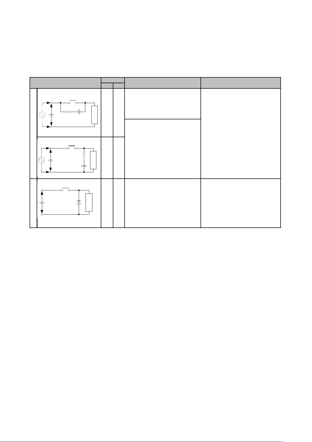
AC DC
If this circuit is used for timer
loads, leakage current flowing
through cr cause faulty operation.
*If used with AC voltage,
impedance of the load should be
○ ○
D
i
o
d
e
t
y
p
e
×
○
Energy stored in the coil is
discharged to the coil by flow of
current by the diode connected in
parallel to the load and is
consumed by joule heat of the
resistance of the inductive
Use a diode with a peak inverse
voltage 10 times higher than the
circuit voltage and a forward current
as high as or higher than the load
current. In an electronic circuit
where the circuit voltage is not so
high, a diode with a peak inverse
voltage about 2 to 3 times higher
Selection of element
Circuit example
C
R
t
y
p
e
※
△
○
The standard c and r are as follows:
c:0.5 to 1 (μF) per contact current
(1A)
r:0.5 to 1(Ω) per contact vaolage
(1V)
The above values vary depending on
the property of load or variations in
relay characteristic. Considering that
the capacitor "c" has the effect of
controlling the discharge when the
contactes are open and the resistor
"r" plays the role fo controlling the
current at the next power-on, check
through experiments is required.
If the load is a relay or solenoid, the
reset time is delayed. It is effective
to connect between the loads when
the power supply voltage is 24 or
48V and to connect between the
contacts when the power supply
voltage is 100 to 200V
Features/others
r
c
Relay contact
I
n
d
u
c
t
i
v
l
o
a
d
r
c
Relay contact
I
n
d
u
c
t
i
v
e
l
o
a
d
Relay contact
Diode
I
n
d
u
c
t
i
v
e
l
o
a
d
f Contact Protection Circuit
When the inductive load is opened or closed, a counter-electromotive voltage is generated
and causes a heavy damage to the contact, resulting in a significant shortening of operating
life. Therefore, a contact protection circuit is required. The examples of contact protection
circuits are as shown in the table below.
13
Page 16
Check if the connector cable is properly connected.
Contact Tohnichi for repairing.
Remove it and register again.
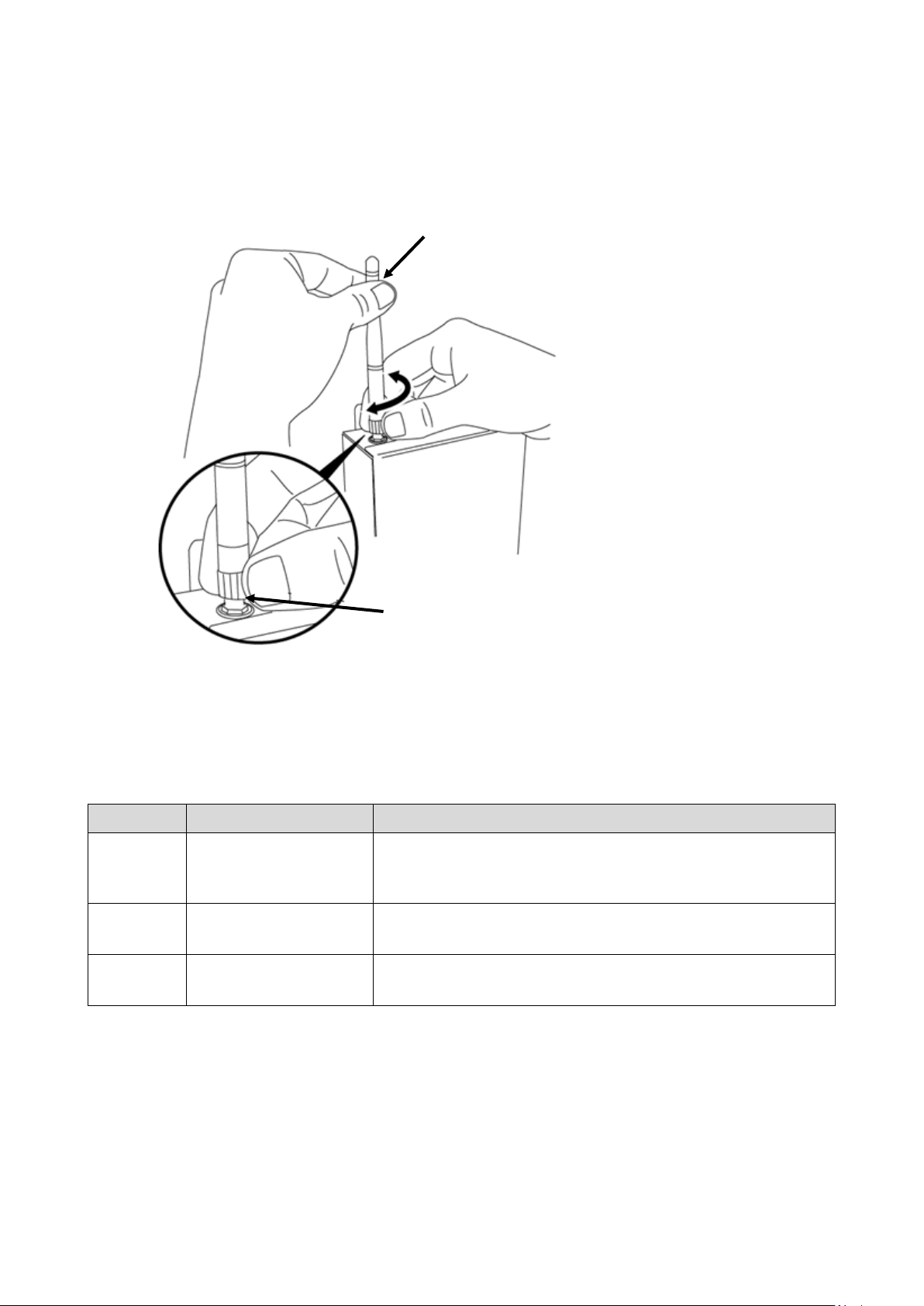
6-3 BL Antenna
Refer to below drawing when mounting or dismounting an antenna on R-BL receiver. Do not
turn antenna itself. Hold the antenna and turn the notched end of the antenna.
Hold the antenna not to rotate
Rotate the jagged part
6-4 Error on R-BL receiver
When following Error codes are indicated on R-BL receiver, cancel each error condition.
Code Description Solution
CTS, Clear to Send signal is undetected.
ERR6 Flow Control Error
ERR8 Memory Abnormality
ERR13 Overlapping
Make sure CTS/RTS flow control.
Memory data is defected. Reset all.
The ID has been registered to a different output already.
14
Page 17
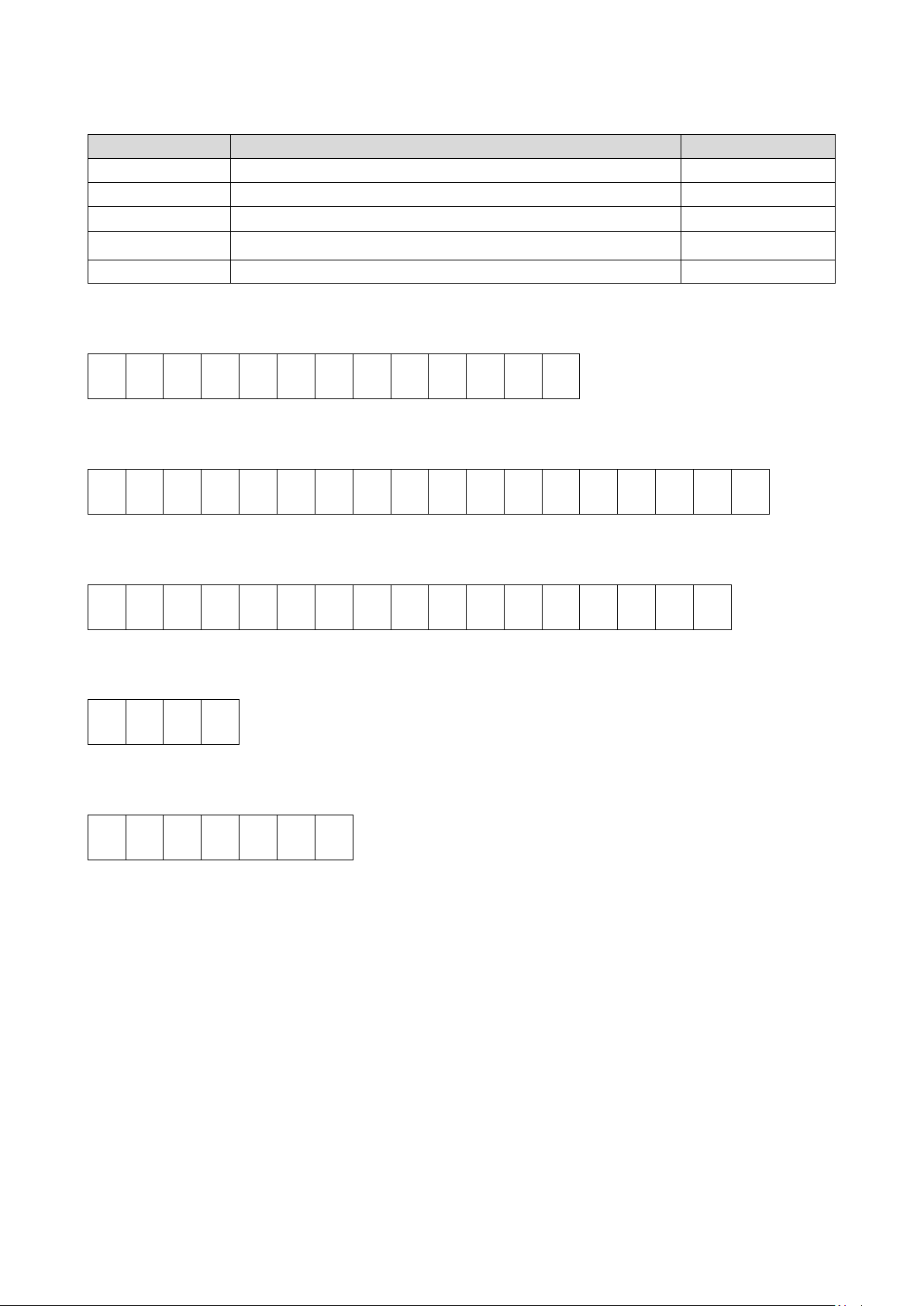
Description
Factory Default
Baud Rate
Selectable 2400/4800/9600/19200/38400/115200bps
115200bps
Parity
Selectable None/Even/Odd
None
Data Length
Selectable 7 or 8 bit
8bit
Flow Control
Selectable ON/OFF, CTS-RTS
off
6-5 RS232C
Stop Bit
Selectable 1 or 2 bit
1bit
Output Format, non registered ID
R E , * * * * * * * * CR LF
Output Format, registered OUT1 to 4
R E , * * * * * * * * , O U T * CR LF
Output Format, registered RS1 to 6
R E , * * * * * * * * , R S * CR LF
Output Format when input LS-IN
R E CR LF
Reset Command Format
A T 1 3 0 CR LF
Input Contact terminal to reset “outputting non-voltag e co ntact s ignal” and “auto-reset”.
15
Page 18
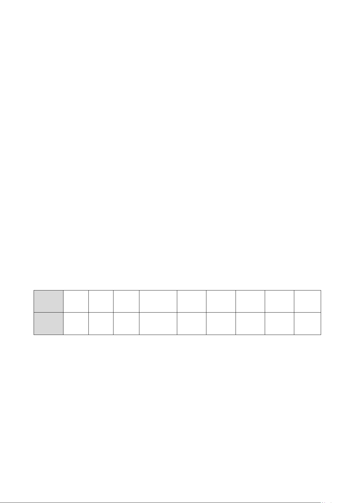
OUT1
RS1
Auto
7 Setting Receiver
7-1 Setting Receiver
As a default setting, BL Receiver receives all signals of BL Transmitter, T-BLA to R-BLA, T-BLE to
R-BLE and T-BL to R-BL. Refer to 7-2, Setting Procedure. ID registered receiver does not receive any
other ID signal. Up to 10 Transmitters can be registered to one receiver. Total 4 IDs output as
non-voltage contact signal and RS232C output. Other 6 IDs output through RS232C only.
OUT1 to OUT4 Register IDs on OUT1 to OUT4
OUT1 to OUT4 outputs ID through contact output and RS232C.
RS1 to RS6 Register IDs on RS1 to RS6
RS1 to RS6 outputs ID through RS232C
Flow Control Select ON/OFF of CTS, RTS control
Baud Rate Select one from 2400, 4800, 9600, 19200, 38400, and 115200bps
Parity Select one from NONE, ODD, and EVEN
Data Length Select one between 7 and 8bit
Stop Bit Select one between 1 and 2bit
Buzzer Sound Select ON/OFF of buzzer sound
Auto Reset Timer Select between 0.0~9.9 seconds
Since R-BL does not receive any signal during the auto reset process, this
function also can be used as double count prevention
Auto reset function will be disabled if set as 0.0 second. In this case, reset can be done only
through reset input or through reset command.
Factory Default
Item
Status Off 115200bps NONE 8bit 1bit ON 0.1 Sec
to
OUT4
To
RS6
Flow
Control
Baud Rate Parity
Data
Length
Stop Bit Buzzer
Reset
Timer
16
Page 19
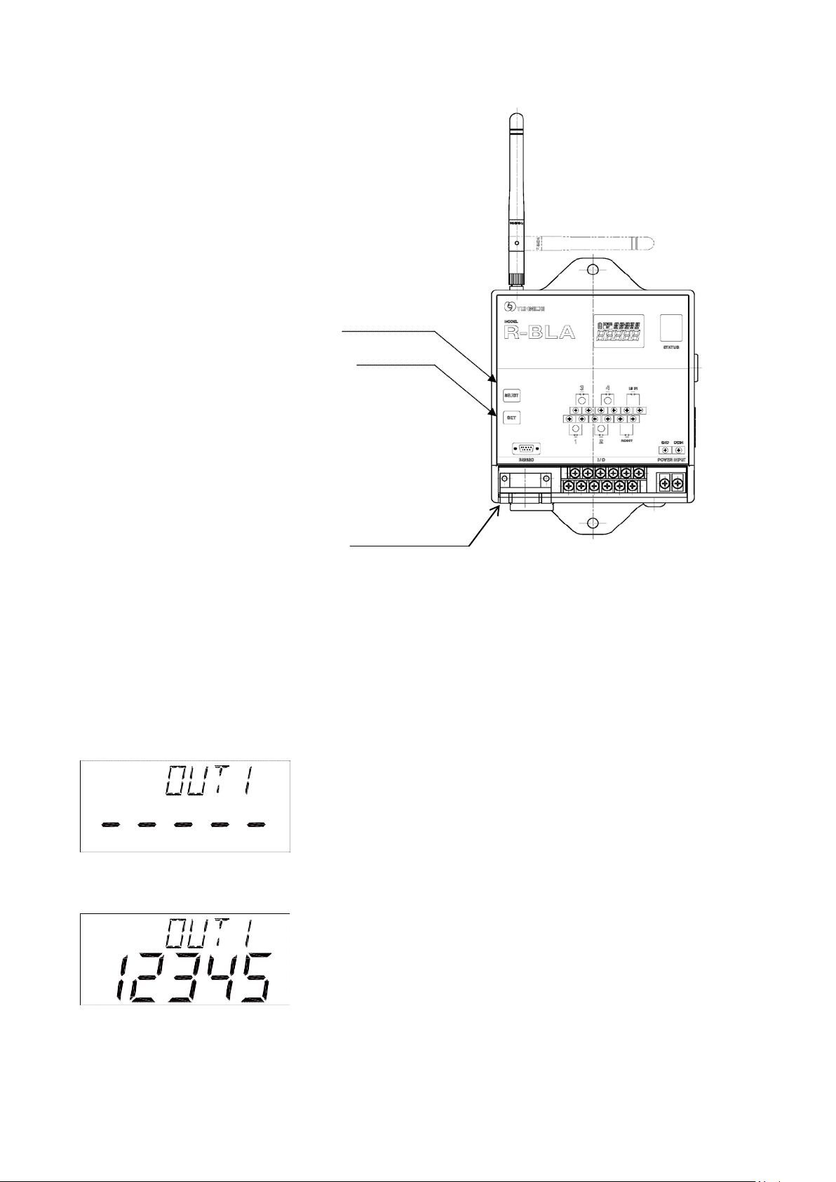
7-2 Setting Procedure
Select Switch
Set Switch
Power Switch
Turn on the power switch while pressing SET key to start mode setting.
Status lamp flashes red and blue when you are in Mode Setting.
In Mode Setting, select BL preference by press “SET” key, from OUT1 to the End.
OUT1-OUT2-OUT3-OUT4-RS1-RS2-RS3-RS4-RS5-RS6-Flow-Baud-Parity-Length-Stop-Buzz-Auto-End
Setting OUT1 to OUT4
“ - - - - -“ is displayed on status screen when no tool is
registered.
Registered 8 digit number of Transmitter ID is displayed.
17
Page 20
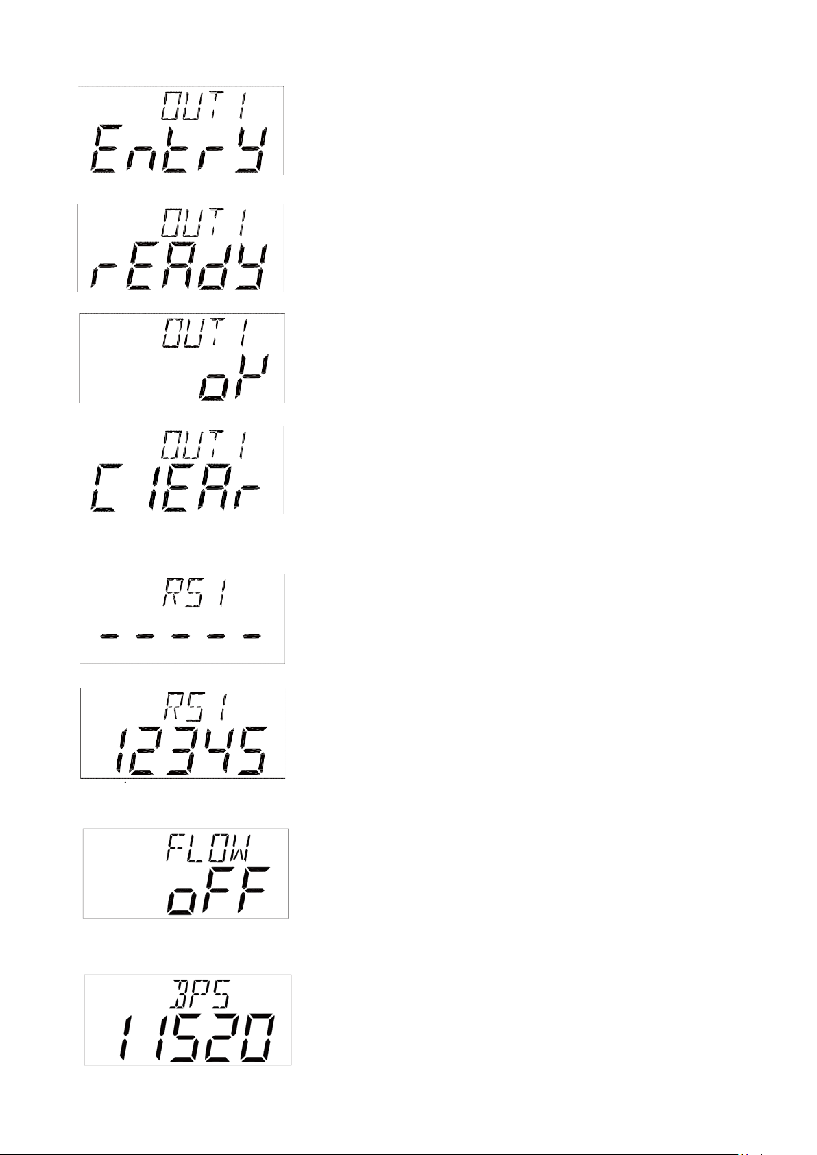
Press The “SELECT” key to choose between “ENTRY”or
“CLEAR”. Select “ENTRY” by pressing the “SET” key.
“READY” appears on screen. Status lamp blinks in red.
Operate BL transmitter and the receiver receives ID. The
registered ID number is displayed on status screen.
To cancel any registered ID, press SELECT key and choose
“CLEAR” and press the SET key.
Setting RS1 to S6
Press “SET” key to register the next tool.
After making a selection, press the “SET” key to go to the
next screen.
Setting Flow Control
Press SELECT key to select ON/OFF of Flow Control.
Setting Baud Rate
Press SELECT key to select a Baud Rate from 2400, 4800,
9600, 19200, 38400, and 115200bps.
18
Page 21
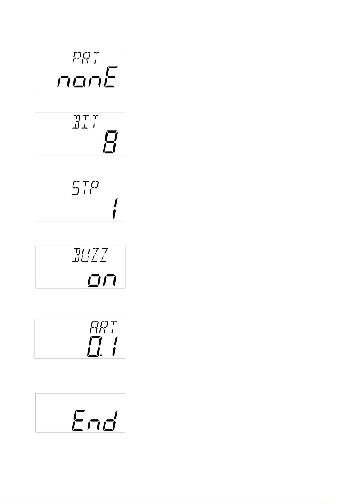
Setting Parity
Setting Data Length
Setting Stop Bit
Press SELECT key to select parity from NONE, ODD, and
EVEN.
Press SELECT key to select data length between 7 and 8 bit.
Press SELECT key to select stop bit between1 and 2 bit.
Setting Buzzer Sound
Setting Auto Reset Timer
END Process
Press SELECT key to select buzzer sound ON/OFF.
SELECT key to increase number. Press SET key to move digit
or end setting. Set 0.0 to 9.9 seconds.
This is the end of settings. Restart the receiver.
19
Page 22
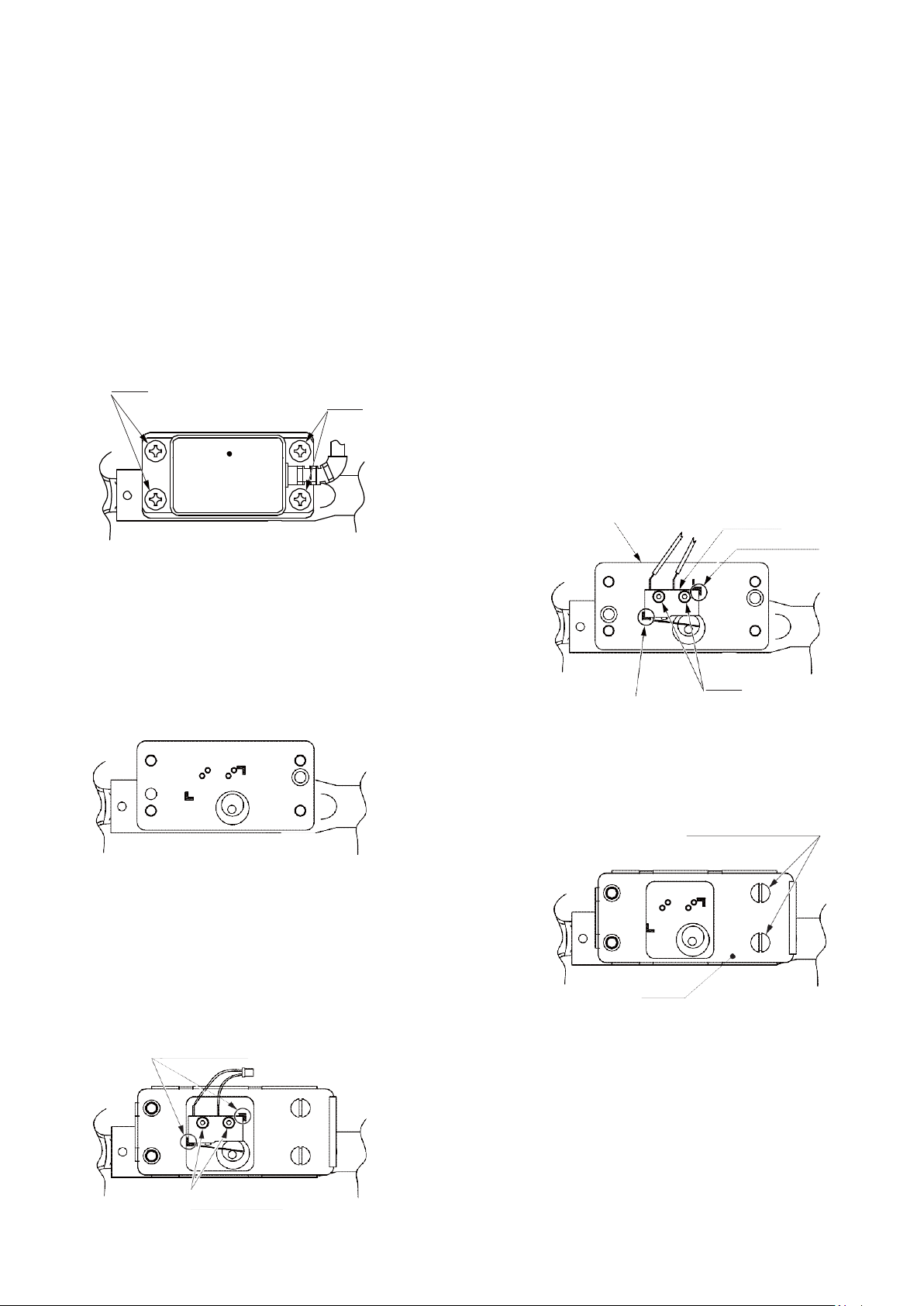
Screws
Screws
Screws
Original Position
Apply Adhesive
Torque 150cN.m
BL Base Plate
Original Position
Apply Adhesive
Torque 25cN.m
8 Mounting Method of BL transmitter onto LS torque wrench
Preparation
T-BL / T-BLA / T-BLE transmitter
Torque drivers 25 and 150 cN.m
e.g. RTD120CN for 25cN.m and RTD500CN for 150cN.m
Hex. Bit w1.5, w3
Minus bit
Philip Driver
LS torque wrench
Loosen 4 screws of LS top cover.
Mark LS position on LS base to make sure the original
position, and loosen two screws of limit switch.
Remove LS Switch
Put attached BL base plate onto LS base. Apply
adhesive and tighten with 150cN.m.
LS Base Plate
Limit Switch
Original Position
Recommended: Three Bond TB1324
Set attached LS switch on the predetermined position.
Apply adhesive and tighten with 25cN.m. There is a
tiny washer for each screw.
Recommended: Three Bond TB1324
Do not pull cables strongly. It may cause short cut.
20
Page 23
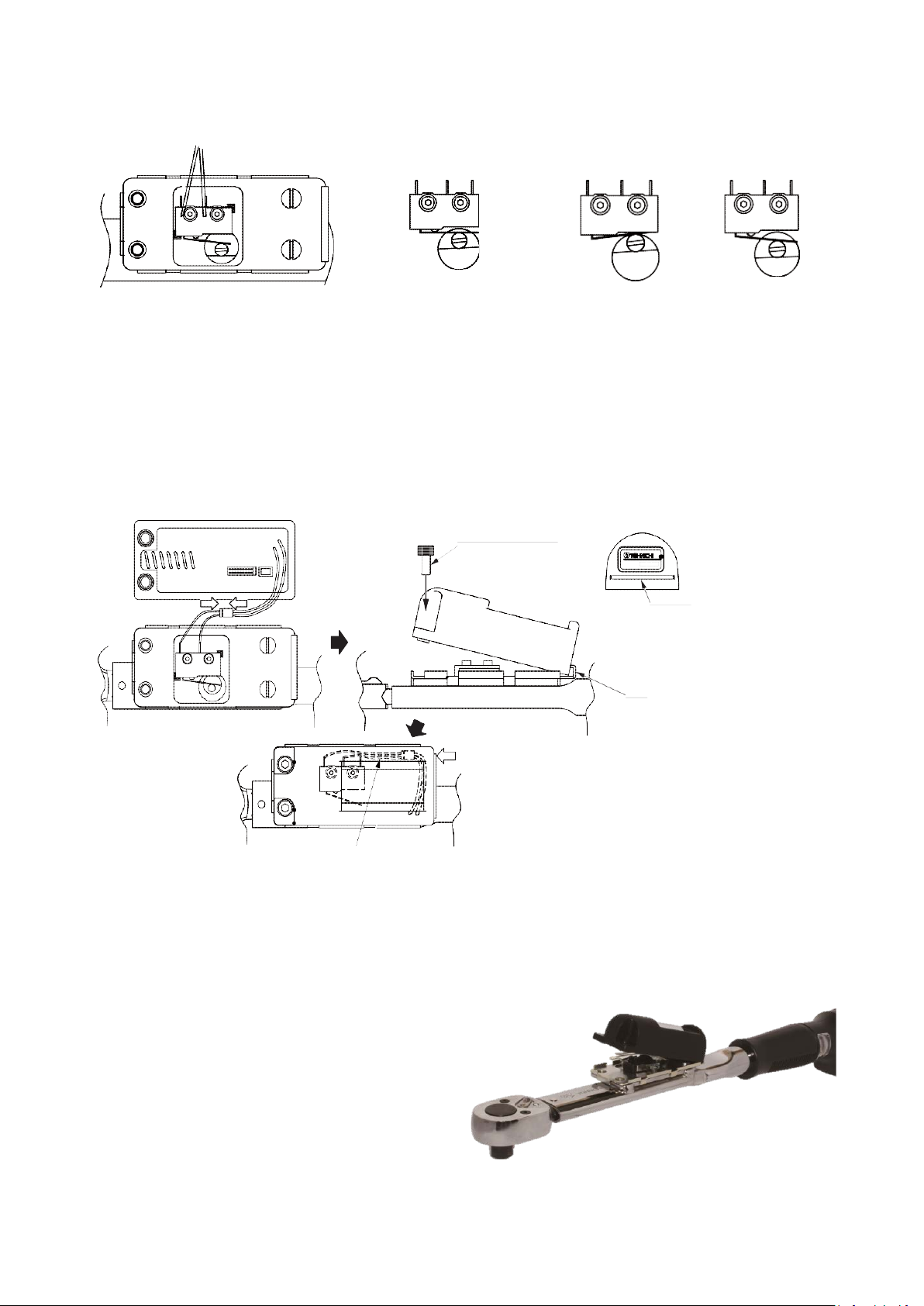
OK, proper position
NG, Too Far
NG, Too Close
Torque 150cN.m
Groove
Jaw
Do not pitch lead wires and connecting coupler.
Figure : Correct wiring of lead cable
After all set, make sure the LS switch position when torque wrench operated.
Connect the coupler and put BL transmitter onto the torque wrench. Hook on jaw and tighten two
screws to 150cN.m. Recommended: Three Bond TB1324
Please perform transmitting test after finishing. If transmission error happens during test, make
sure LS switch position is correct. Check LS lever switch position when torque wrench clicks. If
further problem, contact Tohnichi.
21
Page 24
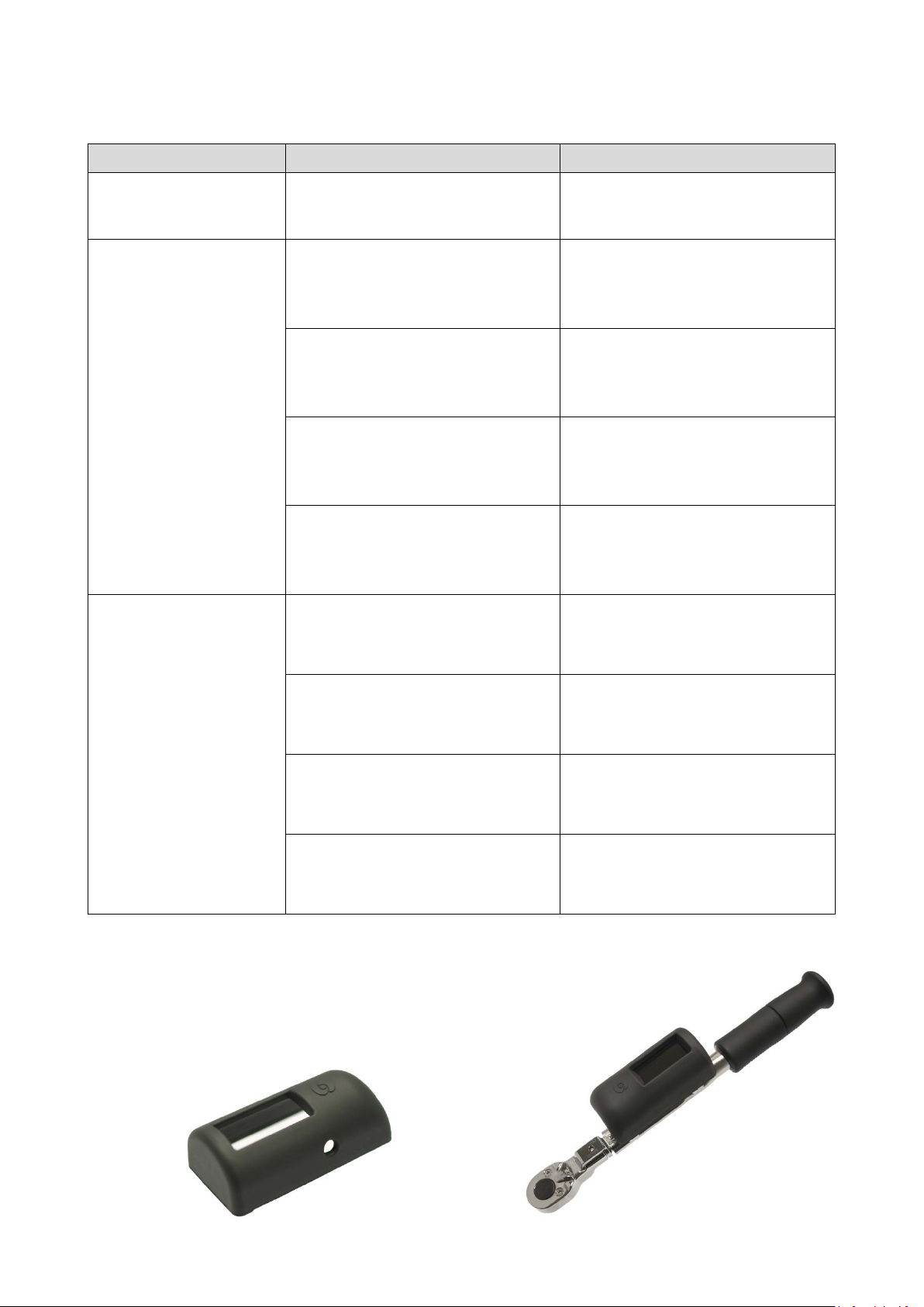
9 Troubleshooting
Phenomenon Causes Solutions
Decreasing number of
transmissions
No signal to BL Receiver
Solar panel is dirty. Remove dirt. Do not use thinner.
No Battery Power. Charge battery. Refer to Page 10.
The transmitter ID is not registered
on the receiver.
Refer to 7-2.
Transmitter switch malfunction Ask Tohnichi for Repair
Reset “Auto-Reset Timer” from
Auto-Reset Timer as 0.0 second.
terminal block. Otherwise, adjust
“Auto-Reset” Time.
Improve the reception
Installation Environment
performance by relocating
receiver.
Obstacles
Short Distance
Radio Wave Environment
Antenna
10 Option
BL-PCV
Protective cover for BL, BLA and BLE transmitters.
Improve the reception
performance by relocating
receiver.
Improve the reception
performance by relocating
receiver.
Confirm whether the appropriate
antenna is attached. Check for
damage.
22
Page 25

11 Regulations
Remote control devices, transmitter and receiver meet each requirement for certification.
BLA
For US
T-BLA, Transmitter module FCC ID:SZV-STM332U
R-BLA, Transceiver module FCC ID:SZV-STM300U
For Canada
T-BLA, Transmitter module IC:5713A-STM332U
R-BLA, Transmitter module IC:5713A-STM300U
This equipment has been tested and found to comply with the limits for a Class B digital device, pursuant to Part 15 of
the FCC rules. These limits are designed to provide reasonable protection against harmful interference in a residential
installation. This equipment generates, uses, and can radiate radio frequency energy and, if not installed and used in
accordance with the instructions, may cause harmful interference to radio communications. However, there is no
guarantee that interference will not occur in a particular installation. If this equipment does cause harmful
interference to radio or television reception, which can be determined by turning the equipment off and on, the user
is encouraged to try to correct the interference by one or more of the following measures:
• Reorient or relocate the receiving antenna.
• Increase the separation between the equipment and receiver.
• Connect the equipment into an outlet on a circuit different from that to which the receiver is connected.
• Consult the dealer or an experienced radio/TV technician for help.
Caution:
Any changes or modifications not expressly approved by the party responsible for product compliance could void the
user’s authority to operate the equipment. To comply with FCC RF exposure compliance requirements, this device
must not be co-located or operating in conjunction with any other antenna or transmitter.
For R-BLA RF TRANSCEIVER
This device complies with Part 15 of the FCC Rules. Operation is subject to the following two conditions:
(1) This device may not cause harmful interference, and (2) This device must accept any interference received,
including interference that may cause undesired operation.
Canada Regulatory Compliance Statement
This Class B digital apparatus complies with Canadian ICES-003.
Cet appareil numériqué de ia classe B est conformé à la norma NMB-003 du Canada.
For Customers in Canada
This device complies with RSS 210 of Industry Canada (IC).
Operation is subject to the following two conditions:
(1) this device may not cause interference, and
(2) this device must accept any interference, including interference that may cause undesired operation of this device.
L’utilisation de ce dispositif est autorisée seulement aux conditions suivantes:
(1) il ne doit pas produire de brouillage et
(2) I’utilisateur du dispositif doit étre prêt à accepter tout brouillage radioélectrique reçu, même si ce brouillage est
susceptible de compromettre le fonctionnement du dispositif.
Exposure to radio frequency radiation
The installer of this radio equipment must ensure that the antenna is located or pointed such that it does not emit RF
field in excess of Health Canada limits for the general population; consult Safety Code 6, obtainable from Health
Canada’s website at
www.hc-sc.gc.ca/rpb.
23
Page 26

BLE
For Europe
Manufacture Tohnichi Mfg. Co., Ltd.
2-12, Omori-kita 2-Chome, Ota-ku, Tokyo 143-0016, Japan
Distributed by N.V. Tohnichi Europe S.A.
Industrieweg 27, Boortmeerbeek, B-3190, Belgium
Product T-BLE, RF Transmitter
Standards R&TTE Directive EN 301 489-3 v1.6.1
EN 301 489-1 v1.9.2
EN 60950-1: 2006 + Amd. 11: 2009
+ Amd.1: 2010 + Amd. 12: 2011
+ Amd.2: 2013
Test Report 1044769S-A and 1044769S-C
R-BLE, RF Receiver
Standards R&TTE Directive EN 301 489-3 v1.6.1
EN 301 489-1 v1.9.2
EN 55022: 2010 Class B
EN 61000-3-2: 2014
EN 61000-3-3:2013
EN 55024: 2010
EN 60950-1: 2006 + Amd. 11: 2009
+ Amd.1: 2010 + Amd. 12: 2011
+ Amd.2: 2013
Test Report 1044769S-A, 1044769S-B and 1044769S-D
The product conformity with EMC Directive 89/336/EEC as amended by 92/31/EEC and 93/68/EEC, based on test
results using harmonized standards in accordance with Article10(1) of the Directive.
For China
In accordance with the provisions on the Radio Regulations of the People’s Republic of China, the
following radio transmission equipment, after examination, conforms to the provisions with its
CMIIT ID: 2016DJ2948
Equipment Name T-BLE
Frequency Range 868.3Mhz
24
Page 27

25
Page 28
Tohnichi Mfg. Co., Ltd.
2-12, Omori-Kita, 2-Chome Ota-ku, Tokyo 143-0016, Japan
Tel +81-3-3762-2455
Fax +81-3-3761-3852
E-mail
Website http://tohnichi.jp
N.V. Tohnichi Europe S.A.
Industrieweg 27, Boormeerbeek, B-3190 Belgium
Tel +32 16 60 66 61
Fax +32 16 60 66 75
E-mail tohnichi[email protected]
Tohnichi America Corporation
1303 Barclay Boulevard, Buffalo Grove, IL 60089-4501 USA
Tel +1 847 947 8560
Fax +1 847 947 8572
E-mail
Website http://tohnichi.com
Tohnichi Shanghai Mfg. Co., Ltd.
东
仁扭矩仪器(上海)有限公司
RM. 5 No. 99 Nong1919, Du Hui Road, Minhang, Shanghai, P.R. China
Tel +86 21 3407 4008
Fax +86 21 3407 4135
E-mail
Website http://www.tohnichi-sh.com
 Loading...