


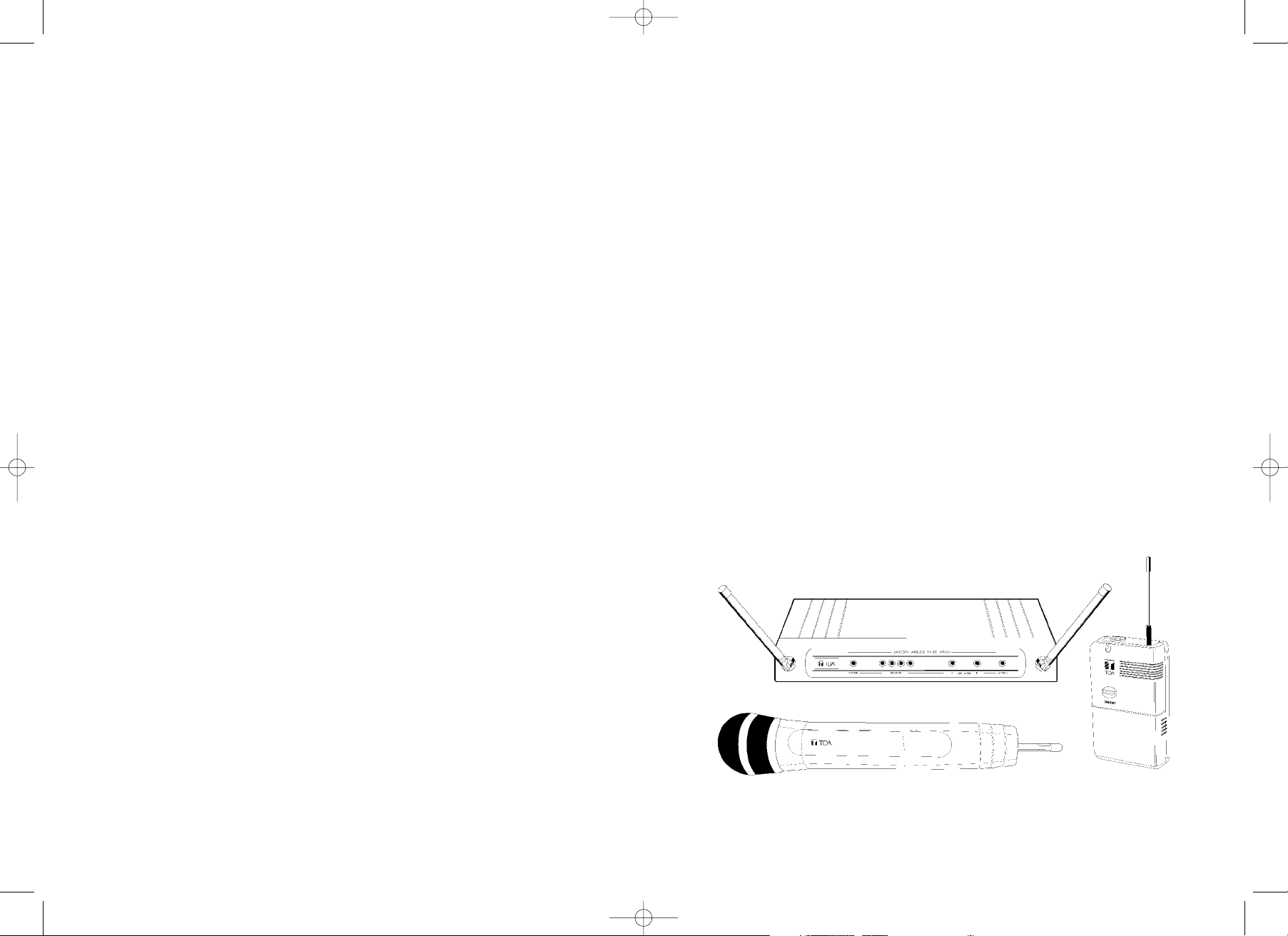
UHF WIRELESS SET
WS-200/300
OPERATING INSTRUCTIONS
Thank you for pur
chasing TOA
’
s UHF Wireless Set.
Please carefully follow the instructions in this manual to ensure long, trouble-free use of your equipment/
Thank you for pur
chasing TOA
’
s UHF Wireless Set.
Please carefully follow the instructions in this manual to ensure long, trouble-free use of your equipment/
Printed in Taiwan
TOA instruction Manual ARTWORK_2 8/5/06 1:22 pm Page 1
CONTENTS
Introduction and Safety
TOA WS System Overview
Receiver Nomenclature and Operation
Handheld Nomenclature and Operation
Lavalier Nomenclature and Operation
General Set-up and Operating Hints and Fault Finding
System Contents Description and System Part Numbers
Technical Specifications
1.
2.
3.
4.
5.
7.
9.
10.
1
TOA instruction Manual ARTWORK_2 8/5/06 1:23 pm Page 3
When Installing the Unit
(Applicable to the Wireless Tuners)
> Do not expose the unit to rain or an environment
where it may be splashed by water or other liquids,
as doing so may result in fire or electric shock.
> Use the unit only with the voltage specified on the
unit. Using a voltage higher than that which is
specified may result in fire or electric shock.
> Do not cut, kink, otherwise damage nor modify
the power supply cord. In addition, avoid using the
power cord in close proximity to heaters, and never
place heavy objects -- including the unit itself -- on
the power cord, as doing so may result in fire or
electric shock.
> A
void installing or mounting the unit in unstable
locations, such as on a
rickety table or a slanted surface. Doing so may
result in the unit falling down and causing personal
injury and/or property damage.
When the Unit is in Use
(Applicable to the Wireless Tuners)
> Should the following irregularity be found during
use, immediately switch off the power, disconnect
the power supply plug from the AC outlet and
contact your nearest TOA dealer. Make no further
attempt to operate the unit in this condition as this
may cause fire or electric shock.
> If you detect smoke or a strange smell coming
from the unit.
> If water or any metallic objects get into the unit.
> If the unit falls, or the unit case breaks.
> If the power supply cord is damaged, (exposure of
the core, disconnection, etc.)
> If it is malfunctioning (no tone sounds.)
> To prevent a fire or electric shock, never open nor
remove the unit case as there are high voltage
components inside the unit. Refer all ser
vicing to
qualified service personnel.
> Do not place cups, bowls, or other containers of
liquid or metallic objects on top of the unit. If they
accidentally spill into the unit, this may cause a fir
e
or electric shock.
(Common to all WS series)
> T
o pr
event the electromagnetic wave from badly
influencing medical equipment, make sure to switch
off the units power when placing it in close
proximity to the medical equipment.
SAFETY PRECAUTIONS
> Before installation or use, be sure to carefully read all the
instructions in this section for correct and safe operation.
> Be sure to follow all the precautionary instructions in this section, which
contain important warnings and/or cautions regarding safety.
> After reading, keep this manual handy for future reference.
Safety Symbol and Message Conventions
Safety symbols and messages described below are used in this manual to prevent
bodily injury and property damage which could result from mishandling. Before
operating your product, read this manual first and understand the safety symbols and
messages so you are thoroughly aware of the potential safety hazards.
WARNING
CAUTION
WARNING
Indicates a potentially hazardous situation which, if
mishandled, could result in death or serious personal injury.
Indicates a potentially hazardous situation which, if
mishandled, could result in in moderate or minor personal
injury, and/or property damage.
CAUTION
When Installing the Unit
(Applicable to the Wireless Tuners)
> Never plug in nor remove the power
supply plug with wet hands, as doing so
may cause electric shock.
> When unplugging the power supply
cord, be sure to grasp the power supply
plug; never pull on the cord itself.
Operating the unit with damaged power
supply cord may cause a fire or electric
shock.
> When moving the unit, be sure to
remove its power supply cord from the
wall outlet. Moving the unit with the
power cords connected to the outlet
may cause damage to the power cord,
resulting in fire or electric shock. When
removing the power cord, be sure to
hold its to pull.
> Avoid installing the unit in humid or
dusty locations, in locations exposed to
the direct sunlight, near the heaters, or
in locations generating sooty smoke or
steam as doing otherwise may result in
fire or electric shock.
> When the unit is in use
(Applicable to the Wireless Tuners)
> Use the specified AC adaptor for the
unit. Note that the use of other adaptors
may cause a fire.
(Applicable to the Wireless Microphones)
> When the unit is not in use for 10
days or more, be sure to take the
batteries out of the unit because battery
leakage may cause a fire, personal injury,
or contamination of environment.
> Make sure to observe the following
handling precautions so that a fire or
personal injury does not result from
leakage or explosion of the battery.
> Do not short, disassemble, heat nor
put the battery into a fire.
> Avoid using both new and old
batteries together.
> Never charge batteries of the type
which are not rechargeable.
> Do not solder a battery directly.
> Be sure to use the specified type of
batteries.
> Note correct polarity (positive and
negative orientation) when inserting a
battery in the unit.
> Avoid locations exposed to the direct
sunlight, high temperature and high
humidity when storing batteries.
23
TOA instruction Manual ARTWORK_2 8/5/06 1:23 pm Page 5

WS SYSTEM OVERVIEW
The TOA WS is a high-quality UHF Wireless Microphone System.
The WS has many features including:-
>> 4 User Selectable Channels - that can be operated simultaneously.
>> Diversity Receiver Operation - to minimise drop-outs
>> User Adjustable Audio Output Level - adjustable on both Jack and
XLR outputs.
>> User Adjustable RSSI/Squelch - enables the user to minimise external
interference.
>> Designed to operate license free in most EU countries.
(EA Band 863-865 MHz)
THE WS COMPRISES OF 2 BASIC DIFFERENT VARIATIONS:-
The Handheld System and the Lavalier Presenters System.
The Handheld System comprises of a fully integrated Handheld Microphone
incorporating a Cardioid Dynamic Capsule and is most suited to General
Vocal Applications.
The Lavalier System comprises of a Lavalier Transmitter which is supplied
with a small Lapel style clip-on Microphone and is ideally suited for General
Presentation/ Theatre applications.
45
INTRODUCTION
The TOA WS Series represents TOA's commitment to providing highquality, affordable Wireless Audio Links using our considerable design
expertise gained over many years as a leading edge manufacturer.
We would like to thank you for purchasing this product and would like you to
spend a short time reading this
Operations Instructions so as to familiarise
yourself with the features of the TOA WS series.
SAFETY
Our aim is to supply you with a product that provides you with countless
hours of trouble free use.
In order to achieve these goals, we recommend the following:-
Keep the system away from direct sources of heat e.g. Central heating
radiators, heaters and direct sunlight.
Should the Transmitters not be used for extended periods of time we
recommend that the batteries should be removed so as to avoid any
potential battery leakage.
Keep the system clean by using a slightly damp cloth. Never use household
cleaning agents or solvents.
Avoid using or storing the system in damp conditions.
Always use the AC power adaptor supplied with the Receiver and
never
remove
the external covers of the equipment, so as to expose the
electronics.
TOA instruction Manual ARTWORK_2 8/5/06 1:23 pm Page 7

WS RECEIVER LAYOUT
RECEIVER OPERATION
1. Connect the appropriate AC adaptor into the DC inlet as marked on the
rear panel and observe the Supply indicator (green Led ) lights up.
2. To provide best diversity operation, angle the antennas to form a ”V” as
per illustration and ensure that the antennas have a good line-of–sight
view of the corresponding transmitter. i.e. Avoid placing large metallic
objects in the transmission path.
3. Initially set the receiver AF gain control to its mid-position and connect
the AF output from either the
1/4 inch Jack or XLR to your Mixing console
or amplifier.
4. Select rear panel Channel Selector Switch (Small screw-driver adjust)
to correspond to Transmitter setting. It is possible to select any of the 4
channels. (
Factor
y set to position 1
).
WS HANDHELD NOMENCLATURE
HANDHELD BATTERY INSERTION
1. Rotate the top collar locking ring in the
direction indicated in the illustration
and gently pull the body downwards.
2. Insert a 9V MN1604 (IEC 6 LR61) PP3 type
alkaline battery, being sure to observe the
correct polarity as marked.
3. Gently slide the body upwards and lock.
Note: Should the Red battery status Led Indicator go out
during operation, this indicates a flattened battery and
should be changed .
CHANNEL NUMBER SETTING (Small screw-driver adjust)
With the Transmitter in the OFF position select a channel to correspond with
the Receiver. It is possible to select any of the 4 channels.
(
Factory set to position 1).
Note: The T
ransmitter only changes Active Channel when turned off
and then on.
67
DIVERSITY A
ANTENNA A
ANTENNA B
POWER
RF SIGNAL
LEVEL
AUDIO
OUTPUT XLR
AC
ADAPTOR
INLET
CHANNEL
SELECTOR SWITCH
AUDIO
OUTPUT JACK
AUDIO
OUTPUT
LEVEL
MUTE/
SQUELCH
CONTROL
AF PEAK O/L
DIVERSITY B
{
ON/OFF
CHANNEL
SELECTOR
GRILLE
LOCKING RING
ANTENNA
BODY
BATTERY
STATUS
INDICA
TOR
TOA instruction Manual ARTWORK_2 8/5/06 1:23 pm Page 9

WS LAVALIRE NOMENCLATURE
LAVALIER BATTERY INSERTION
1. Slide the battery compartment to the rear and hinge up-wards to expose
the battery.
2. Insert a 9V MN1604 (IEC 6 LR61) PP3 type alkaline battery, being sure to
observe the correct polarity as marked.
Note: Should the Red battery status Led Indicator go out during operation, this
indicates a flattened battery and should be changed .
MICROPHONE CONNECTION
1. Connect small lapel-type microphone into the corresponding 3.5mm Top
Panel Socket.
2. Ensure that the Battery Compartment
MIC/INST switch is set to
Mic position.
3. Clip the microphone to your clothing (normally Tie or Jacket Lapel). Route
the mic cable so as to avoid undue strain or friction. Try and keep the mic
cable away from the
ANTENNA
The microphone supplied with the WS as a Omni-directional response,
which means it will pick up sounds from all directions. In view of this we
recommend that the microphone is placed as close as possible to the required
sound source.
LAVALIER GAIN CONTROL ADJUSTMENT. (Small screw-driver adjust)
If required adjust the Transmitter AF gain control so as the signal only very
occasionally allows the
Red AF O/L Peak Led on the receiver to light.
CHANNEL NUMBER SETTING (Small screw-driver adjust)
With the Transmitter in the
OFF position, select a channel to correspond with
the Receiver. It is possible to select any of the 4 channels.
(
Factory set to position 1).
Note: The Transmitter only changes Active Channel when turned off and then on.
89
ROTATING
BELT
CLIP
BA
TTERY
STATUS
INDICATOR
BATTERY/
CONTROL
HOUSING
AUDIO
INPUT
ANTENNA
LAPEL MICROPHONE
ON/OFF
SWITCH
AF GAIN ADJUST
CHANNEL SELECT
MIC/INSTRUMENT SWITCH
TOA instruction Manual ARTWORK_2 8/5/06 1:23 pm Page 11

GENERAL SETUP AND OPERATING HINTS
1. DISTANCE.
To maximise operating distance (approximately 100m). We recommend
you follow the following guidelines.
a. Ensure good line of sight between Transmitter and Receiver. Do not place
large obstructions between receiver and transmitters e.g. Concrete walls,
large metal obstructions. In addition keep the receiver away from metallic
beams and obstructions as these can adversely affect the Antenna Pick-up
Pattern and induce interference.
b. Always ensure that the Transmitter is at least 3m (10 feet) away
from the Transmitter.
c. Conduct a “Walk test” which involves you moving the Transmitter in the
area transmission is required and noting the received RF signal strength on
the receiver bargraph. Reception is best with all 4 Leds lit.
d. Never position the Transmitter Antenna directly against the body or hand.
This will have the effect of reducing the operating range considerably.
2.
MULTICHANNEL OPERATION OF THE WS.
The WS is designed for simultaneous use of four systems.
a. Ensure each system is assigned a different operating channel. The
channels are adjusted as per the illustrations. It is important that each
Transmitter/Receiver combination has it’s own unique channel numbered 1-4.
Note: The Transmitter only changes Active Channel when turned off and then on.
b. We recommend that the Receivers are spaced slightly apart and not stacked
directly on top of each other to avoid disturbance to the Receivers
Antennae.
c. Try to ensure that each Transmitter is separated by 0.5m (1.5 feet) during
operation.
Note: TOA cannot guarantee multichannel compatibility with other brands/make
of product.
3.
SQUELCH/RSSI SET UP.
The WS incorporates a
F
ixed
N
oise
Squelch and a variable “Received
Signal strength” Mute Control on the rear panel of the Receiver. This
function is to reduce or eliminate the effect of interference from
outside sour
ces.
To adjust follow these steps:
a. Turn-off the Transmitter and note if any interference is present by
monitoring the Receiver RF Bargraph or Audio Output.
b. Turn the Squelch Control clockwise until the interference disappears.
In extreme cases it may not be possible to remove the unwanted
interference and in this case it is recommended you try an alternative
channel.
Note: that the Squelch Control affects the operating range of the system and with the
Squelch set to maximum, the range will be significantly reduced.
4.
RECEIVER AF GAIN ADJUST.
The WS receiver gain is continuously adjustable between Mic and
Line level.
Should the receiver signal be too high it will distort your mixer/amplifier.
If the signal is too low the result will be an increase in general
background noise.
Adjust this control to achieve the best signal quality.
5.
BATTERY INFORMATION.
Please note that this product is designed to be used with a 9V Alkaline
battery. Should you use a rechargeable cell, be sure not to force it into the
battery compartment as some types can be considerably larger than
standard types and note that the operation time will be much reduced.
6.
LOW-BATTERY STATUS INDICATOR ON TRANSMITTERS.
In normal circumstances, with the use of an Alkaline 9V battery, the
Transmitters should provide approximately 10hrs of continuous use.
Should the Battery indicator go out, it is advisable to change the battery
as soon as possible.
FAULT-FINDING.
In the event of a problem it is worth checking the following check list.
1.
No RF Signal Indication on Receiver!
a. Is the Receiver and Transmitter on the same channel?
b Is the battery fresh in the Transmitter and the battery indicator lit?
2.
No Audio Signal!
a. Is the AF Gain Control set correctly on the Receiver?
b.
Is the
Squelch Control set correctly (Normally mid-position).?
c. Is the MIC/INST switch in the correct position on the Beltpack?
10 11
TOA instruction Manual ARTWORK_2 8/5/06 1:23 pm Page 13

WS-300 SYSTEM:
Receiver
Beltpack Transmitter
Mains AC Adaptor
Lapel type Microphone
Operating Instructions
SYSTEM PART NUMBERS
WS-200 SYSTEM:
Receiver
Handheld Transmitter
Mains AC adaptor
Microphone stand mount/adaptor
Operating Instructions
TECHNICAL SPECIFICATIONS:-
OVERVIEW.
Fully synthesised 4 channel PLL Quartz Controlled FM Wireless Microphone
System incorporating a Dual Conversion Diversity Receiver with Integral Audio
Dynamics Processor.
OPERATING FREQUENCIES:
Band D21 863.150, 863.725, 864.150, 864.850MHz
Band B21 742.075, 742.800, 743.300, 743.975MHz
Band A21 719.025, 719.600, 720.450, 720.875MHz
AF S/N RATIO: > 96dBA
AF FREQUENCY RESPONSE: Handheld 80Hz – 16KHz +/- 3dB.
Beltpack 60Hz - 16KHz +/- 3dB
AF THD: less than 1%
OPERATING TEMPERATURE RANGE:
-10
0
- +450C / 95 relative humidity.
RECEIVER
POWER CONSUMPTION: 12V @ 100mA
FIRST IF FREQUENCY: 55.875MHz
SECOND IF FREQUENCY: 10.700MHz
AF OUTPUT: Variable to +10dBu unbalanced via 1/4 inch mono Jack
socket.
+16dBu Balanced via XLR 3F connector Pin 2 +.
INDICATORS: 4 position RF Bargraph, AF peak (overload), Power,
Diversity A/B.
CONTROLS: Channel select, AF output, Squelch.
DIMENSIONS: 35 x 213 x 98mm.
WEIGHT:
A
ppr
ox 580g
BELTPACK DESCRIPTION
WS-300 D21UK 863-865MHz
UK Power supply
WS-300 D21ER 863-865MHz
EU Power supply
WS-300 B21UK 742-744MHz
UK Power supply
WS-300 B21ER 742-744MHz
EU Power supply
WS-300 B21US 742-744MHz
US Power supply
WS-300 A21US 719-721MHz
US Power supply
HANDHELD DESCRIPTION
WS-200 D21UK 863-865MHz
UK Power supply
WS-200 D21ER 863-865MHz
EU Power supply
WS-200 B21UK 742-744MHz
UK Power supply
WS-200 B21ER 742-744MHz
EU Power supply
WS-200 B21US 742-744MHz
US Power supply
WS-200 A21US 719-721MHz
US Power supply
WS SYSTEM PACKAGE CONTENTS
12 13
TOA instruction Manual ARTWORK_2 8/5/06 1:23 pm Page 15

NOTES
HANDHELD TRANSMITTER
POWER CONSUMPTION: 9V @ <50mA.
OPERATING TIME: approx 10 hours.
OUTPUT POWER: 10mW max.
CONTROLS: Frequency select, On-off switch.
INDICATORS: Battery status Led.
TRANSDUCER TYPE: Dynamic with Cardioid pattern.
DIMENSIONS: 280 x 50mm max. (including grille)
WEIGHT: Approx 210g
LAVALIER TRANSMITTER
POWER CONSUMPTION: 9V @ <50mA.
OPERATING TIME: approx 10hours.
OUTPUT POWER: 10mW max.
CONTROLS: Frequency select, On-off switch, Lapel/Instrument
switch, Gain adjust.
INDICATORS: Battery status Led.
CONNECTORS: AF input via 3.5mm socket.
Tip = Audio.
Ring + sleeve = Gnd.
LP2 LAVALIER
MICROPHONE
: Back electret condenser
microphone with omni-directional pattern.
DIMENSIONS: 60 x 100 x 30mm mm including belt clip.
WEIGHT:
A
ppr
ox 90g
TYPE APPROVALS. ETSI 300-422, FCC pt 74 h, IC
14 15
TOA instruction Manual ARTWORK_2 8/5/06 1:23 pm Page 17

16
NOTES
TOA instruction Manual ARTWORK_2 8/5/06 1:23 pm Page 19
 Loading...