

Page 1
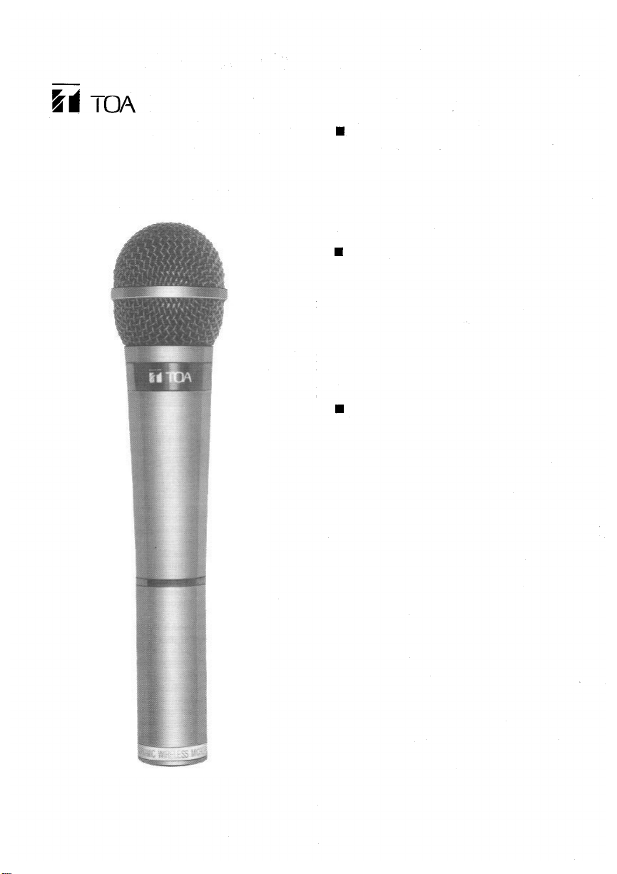
[Operating Instructions]
WIRELESS
MICROPHONE
WM-280
WM-281
Please fol lo w the i nstruct ions in thi s manual to obtain
the optimum results fr om this unit. We also recommend you keep this manual handy for future reference.
GENERAL DESCRIPTION
The TOA WM-280 (WM-281) is a hand-held vocal
wireless microphone incorporating a uni-directional
dynamic microphone, and a compressor/expander
system noise reduction circuit to minimize the
influence of high-frequency noise generated from
digital equipment such as personal computers and
word processors.
FEATURES
• Ideal for vocal applications.
• Maximum input level of 144 dB sp l .
• Continuous operation f or 12 hours or more on one
alkaline battery.
(LR6/1.5V)
• Two battery indicators (green and red).
• Internal I.D. signal generator for tone squelch.
• Stopper to prevent the fall of a battery case.
• Compressor/expander system noise reduction circuit.
USER PRECAUTIONS
• Take care not to drop the unit on to a hard floor.
• Do not flip nor blow into the microphone head.
• Avoid placing the unit in areas of ex tremely high
humidity and temperature.
• Never open the unit nor touch its internal components.
• Clean the unit's exter ior periodically with a s oft dry
cloth. If it gets very dirty, wipe first with a soft damp
cloth lightly soaked in a neutral detergent, and then
dry with a soft cl o t h .
Never use thinner, benzine, or other solvents, which
may damage plastic part o f the unit.
• Remove the battery if the unit is to be stored for two
weeks or more.
TOA Corporation
Page 2
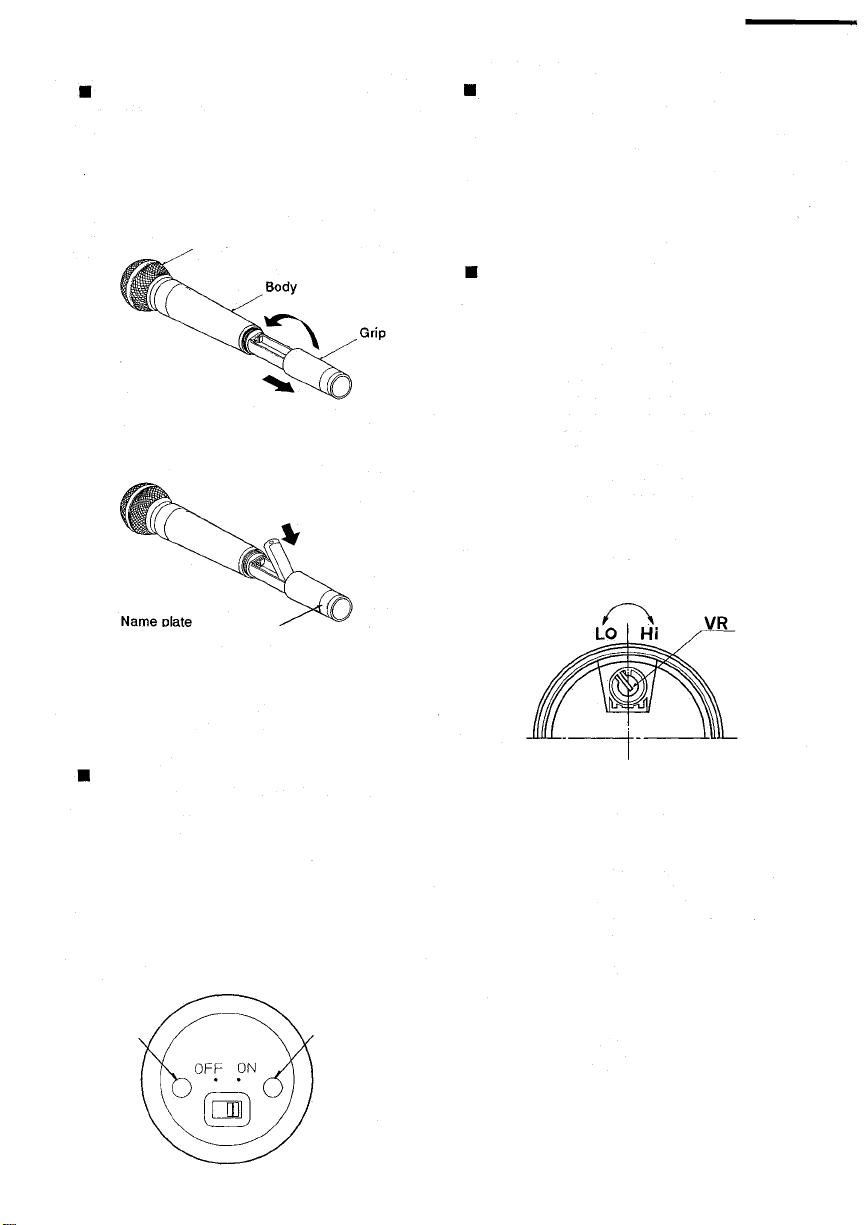
BATTERY LOADING
Use LR6 type alkaline battery.
1. Hold the microphone body and rotate the microphone grip anticlockwise. (Fig. 1) The microphone
grip is so designed that it can not be completely
removed from the body because the battery grip
past the lock point as damage may occur.
Microphone head
Fig.1
2. Observing corre ct polarity instructed inside the
battery compartment, insert a battery. (Fi g . 2)
Fig.
2
(Color identification label)
HOW TO USE
1. Verify that the receiver frequency is identical w ith
the microphone (transmitter) frequency.
2. Set the microphone on/off switch to ON, and verify
that the green battery indicator lights.
3. Set the on/off switch to OFF after use and verify
that the green LED is extinguished.
SENSITIVITY SETTING
The maximum input sensitivity of this microphone can
be set in the range of from 128 dBspl to 144 dBspl.
(Factory-preset to 136 dBspl.) If the user's mouth is
put exteremely close to the microphone, and speaking
loud into th e microphone the amplifier is overloaded,
thus resulting in sound distortion. Conversely, if used
away from the microphone, the sufficient S/N ratio
may not be obtained due to low-level sound pickup.
In such cases, observing the receiver's level meter,
adjust the microphone gain control as follows:
1.Set the receiver's power switch to ON. Then set
the microphone's power switch to ON and co nfirm
that the receiver receives a radio signal.
2. Use a Philips type screwdriver to adjust the gain
control, as shown in Fig, 4.
Rotate the control clockwise to increase the
sensitivity, and counter-clockwise to decrease it.
3. Replace t he microphone grip by sliding the grip
upward and hand tightening the grip in a clockwise
position.
BATTERY REPLACEMENT
1. The alkaline battery LR6 can be continuously used
for approximately 12 hours. (The manganese
battery R6 fo r approximately four hours.)
2. Battery indicator
When the battey voltage is sufficient, the green
LED lights. The green LED becomes dimmer as
the battery voltage drops, and the red LED lights.
In such a case, renew the alkaline battery LR6
inside an hour or two (renew the manganese
battery R6 inside a half hour.).
Red LED
Fig.
3
Green LED
Fig.
4
3. Speaking loud into the microphone, adjust the gain
control that the level indica tor lights yellow. There
is no fear of sound distortion if the indicator lights
red just occasionally.
4. If the receiver to be used is the WT-780 or WT-781,
of which level indicator only indicates a peak level,
similarly adjust the gain control so that the peak
indicator lights just occasionally when the voice
input is at its maximum.
Page 3

TIPS FOR CONVENIENT USE
1. Strength and direction of a radio signal to be
transmitted from the wireless microphone change
depending on the part of the microphone body to
be held by the hand. To prevent this, hold the
upper part of the body.
2. To aviod feedback, use the microphone with your
mouth put as close to the microphone top as
possible.
3. Adjust the tuner volume control to an appropriate
volume level that prevents feedback. The system is
prone to feedback if the microphone comes too
close to the speaker. It is suggested that tests be
performed preliminarily of feedback points in loca-
tions where the microphone is to be acutally used.
4. To prevent radio interference or malfunction of the
tuner, always use the microphone at least 3m (10
feet) away from a receiving antenna.
5. When using multiple microphones simultaneously,
separate them at least 60cm (2 feet) from each
other to prevent noise or break in sound, which
may result f r o m mutual microphone interference.
6. Walls, floors, and ceilings block the radio wave's
straigh-line travel, and frequently create null spots
that can cause temporary loss of signal reception
even within the practical transmission distance
threshold. In such cases, relocate a receiving
antenna or change microphone locations. (To
effectively reduce the null spots, use the diversity
tuner instead of non-diversity tuners.)
7. Human bodies absorb radio signals, and this can
badly affect signal reception. In rooms having a
number of people, attempt to install an antenna
high above the floor.
8. Once a w ireless system is installed, actually move
around the site wit h a microphone to check system
operation.
9. Color Identification Labels
Identification labels of different colors are supplied
with the wireless microphone to simplify confir-
mation of microphone frequencies when multiple
microphones are in use. Attach one of the labels to
the microphone. In this event, both the microphone
and its corresponding receiver need to be in the
same color scheme f or easy association with their
frequencies.
The squelch circuit of TOA's wireless systems consists of both the tone and noise squelches, and is not
actuated if only same RF carrier as the receiving
frequency is received. It is so designed as to be
actuated and output a signal only when the received
RF carrier contains a very exact pre-determined tone
frequency component. Therefore, disturbing radio
signals are rejected and the speaker can be kept
completely quiet when the wireless microphone's
power switch is set to OFF, ensuring reliable use in
every application.
PART NAME
Grip
ADDITIONAL EXPLANATIONS
Squelch circuit
In a receiver employing only a noise or carrier
squelch, the squelch circuit is actuated and provides
the output whenever the receiver receives the same
RF carrier as a receiving frequency. This causes
even a disturbing radio signal to be received prov ide d
its frequency is the same as the receiving frequency.
As a result, it can happen that sound is suddenly
heard fr om the speaker due to disturbing radio signal
even when the wireless microphone's power switch is
left OFF.
Battery indicator
Power switch
Unit: mm (in.)
Page 4
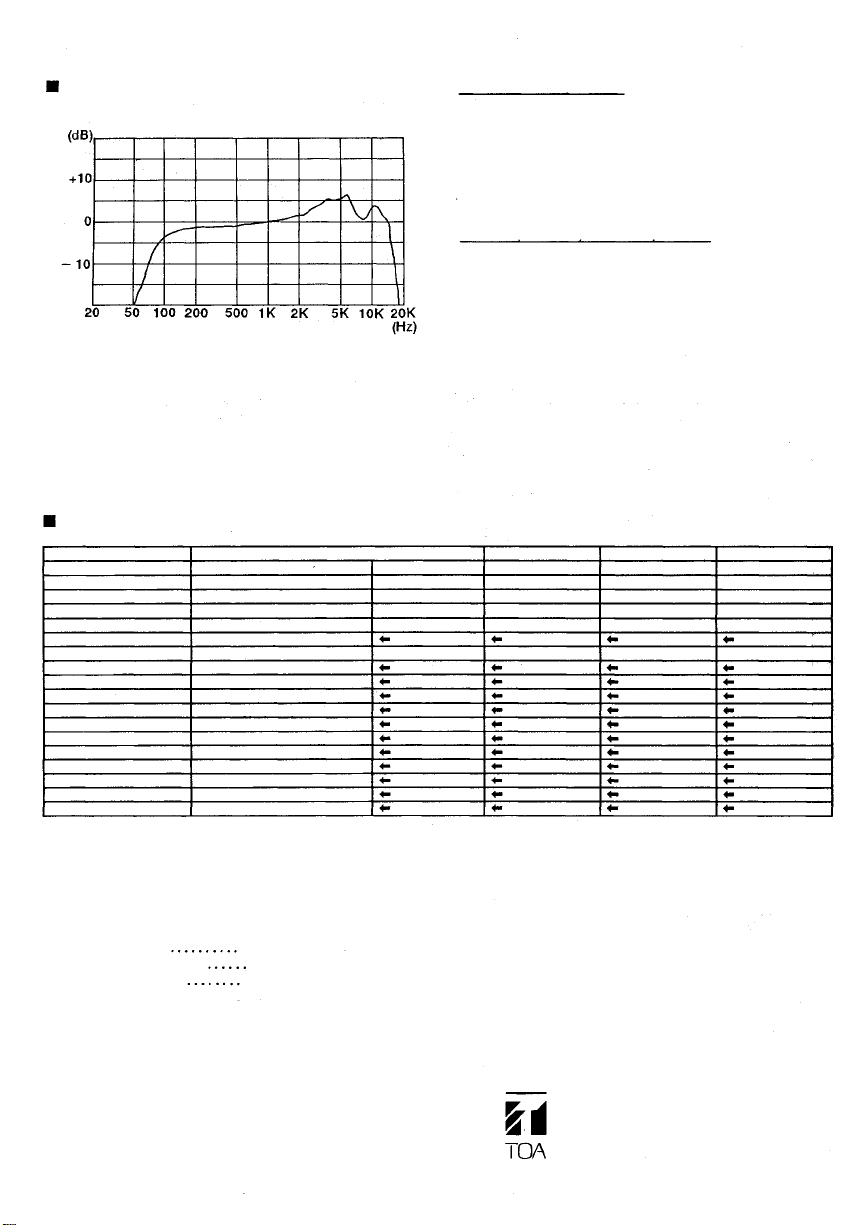
TYPICAL FREQUENCY RESPONSE
• FCC license requirement
The operation of the TOA wireless microphone sys-
tems must conform with the rules and regulations
contained in the code of Federal Regulations, 47,
IN dB
Telecommunications, Part 74 and Part 90. These
regulations are available fr om the U.S. Government
Printing Office.
• D.O.C. (CANADA) license requirement
RESPONSE
The Department of Communication (D.O.C.) recom-
216 MHz band be licensed on the following basis:
RELATIVE
FREQUENCY IN HERTZ
2) frequencies shall be selected and assigned form
3) operational areas shall be restricted to locations
4) location of operation to be shown on license; and
5) licenses shall resolve interference complaints that
SPECIFICATIONS
Versions
Regulations
Carrier Freq. Range
Freq. Stability
RF Carrier Power
Effective Radiated Power
Input Range
Modulation (Max.)
Tone Freq.
Controls
Battery
Current Drain
Battery Life
Battery Indicator
Antenna
Ambient Temperature
Colour
Dimensions
Weight
FCC Part 90
169.445 ~171.945MHz
± 0.005%
15mW
128~144 dBspl
± 15kHz Deviation
32.768kHz
Power ON/OFF
LR6 (1.5 Volts) Alkaline
90mA Typ. (1.5V)
More than 12 hours
Green and Red LED's
Internal Dipole
–10°C~50°C (14°F~122°F)
Dark Gray
Ø50 x 225mm (Ø1.97" x 8.86")
390g (0.858 Ibs.) with battery
WM-280 US version
FCC Part 74
174 ~216MHz
± 0.005%
15mW
± 40kHz Deviation
*Specifications are subjects to change without notice.
mends wireless microphones operating in the 174 ~
1) on a no-protection non-interference basis;
within television channels 7 to 13 (174 ~ 216 MHz);
that are at least 8 miles outside the Grade B
contour of television stations that operate on the
channel in which the frequency assignment falls;
result from microphone operation.
WM-281 CA version
D.O.C.
174 ~216MHz
0.005%
15mW
± 15kHz Deviation
WM-280 UK version
MPT
1345
173.8 ~175.0MHz
± 10kHz
Less than 2mW
± 40kHz Deviation
WM-280AS version
DOC 60
202.1 ~203.7MHz
0.002%
15mW
± 15kHz Deviation
• Accessories:
Microphone holder
Color identification labels
Operating instructions
1
1
1
TOA Corporation
KOBE, JAPAN
133-07-064-40
 Loading...