

Page 1
Please follow the instructions in this manual to obtain the optimum results from this unit.
We also recommend that you keep this manual handy for future reference.
WM-2110DESK-TOP TRANSMITTER
OPERATING INSTRUCTIONS
1. SAFETY PRECAUTIONS
• Be sure to read the instructions in this section carefully before use.
• Make sure to observe the instructions in this manual as the conventions of safety symbols and messages
regarded as very important precautions are included.
• We also recommend you keep this instruction manual handy for future reference.
Indicates a potentially hazardous situation which, if mishandled, could
result in death or serious personal injury.
WARNING
• Do not expose the unit to rain or an environment where it may be splashed by water or other liquids, as
doing so may result in fire or electric shock.
• Use the unit only with the voltage specified on the unit. Using a voltage higher than that which is specified
may result in fire or electric shock.
• Do not cut, kink, otherwise damage nor modify the power supply cord. In addition, avoid using the power
cord in close proximity to heaters, and never place heavy objects -- including the unit itself -- on the power
cord, as doing so may result in fire or electric shock.
• Avoid installing or mounting the unit in unstable locations, such as on a rickety table or a slanted surface.
Doing so may result in the unit falling down and causing personal injury and/or property damage.
• To prevent lightning strikes, install the unit at least five meters away from a lightning rod, and yet within the
protective range (angle of 45°) of the lightning conductor. Lightning strikes may cause a fire, electric shock
or personal injury.
• Since the unit is designed for in-door use, do not install it outdoors. If installed outdoors, the aging of parts
causes the unit to fall off, resulting in personal injury. Also, when it gets wet with rain, there is a danger of
electric shock.
• Should the following irregularity be found during use, immediately switch off the power, disconnect the power
supply plug from the AC outlet and contact your nearest TOA dealer. Make no further attempt to operate the
unit in this condition as this may cause fire or electric shock.
· If you detect smoke or a strange smell coming from the unit.
· If water or any metallic object gets into the unit
· If the unit falls, or the unit case breaks
· If the power supply cord is damaged (exposure of the core, disconnection, etc.)
· If it is malfunctioning (no tone sounds.)
• Do not place cups, bowls, or other containers of liquid or metallic objects on top of the unit. If they
accidentally spill into the unit, this may cause a fire or electric shock.
• Do not touch a plug or antenna during thunder and lightning, as this may result in electric shock.
Indicates a potentially hazardous situation which, if mishandled, could
result in moderate or minor personal injury, and/or property damage.
CAUTION
• Never plug in nor remove the power supply plug with wet hands, as doing so may cause electric shock.
• When unplugging the power supply cord, be sure to grasp the power supply plug; never pull on the cord
itself. Operating the unit with a damaged power supply cord may cause a fire or electric shock.
• Use the dedicated AC adapter for the unit. Note that the use of other adapter may cause a fire.
Page 2
2. GENERAL DESCRIPTION
TOA's WM-2110 is a Desk-top Transmitter designed to use 470 MHz band radio signals.
3. FEATURES
• The remote control function permits the unit's transmission to be controlled from external equipment.
• Input sensitivity can be switched between MIC and LINE signal levels depending on the type of equipment to
be connected to the input.
• A maximum of 5 different channels can be simultaneously used in the same location.
• Compact size and high reliability.
4. HANDLING PRECAUTIONS
• Take care not to drop the unit onto the floor nor bump it against a hard object as the unit could fail.
• To clean, wipe with a dry cloth. When the unit gets very dirty, use a cloth damped in a neutral cleanser.
Never use benzene, thinner or chemically-treated cleaning cloth because such volatile liquids could deform
or discolor the unit.
• Keep the unit as far away as possible from a fluorescent lamp, digital equipment, PC or other equipment
which generate high frequency noise.
• To ensure correct signal transmission, do not place metal objects or other impediments which block radio
wave travel around the unit.
• Be sure to install the antenna vertically as doing otherwise may result in transmission failures.
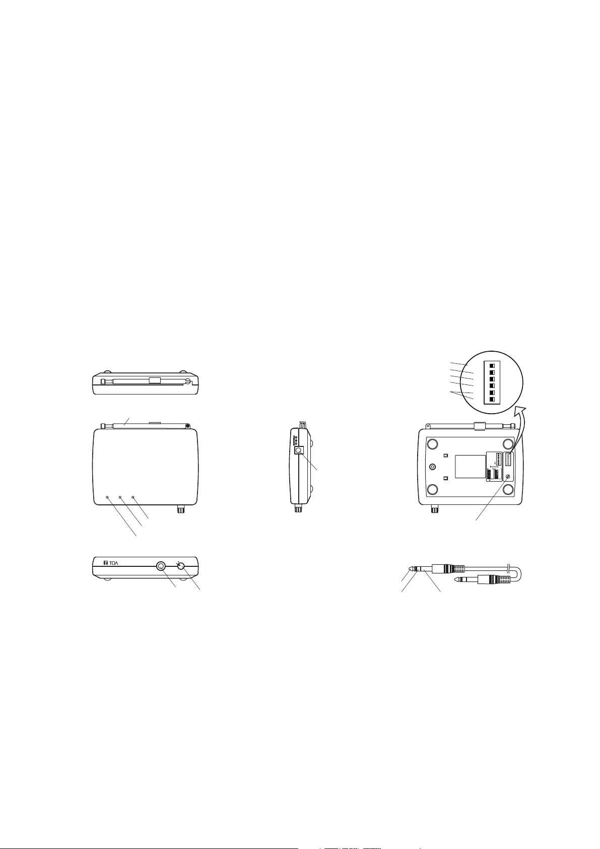
5. NOMENCLATURE
Antenna
Audio signal peak indicator
Power indicator
Channel selector switch
3-pole phone plug cord
Transmission indicator
DC inlet
Input
Audio input
Remote GND
Power switch
POWER TX
INPUT
OFF
ON PWR
AF PEAK
[Rear]
[Top]
[Side]
[Bottom]
[Accessory]
[Front]
WM-2110
MIC/LINE
INPUT
SENS.
MIC
SW position
–66
–60
–54
–24
–18
1
2
3
4
5
–12
LINE
Channel
–
–
REMOTE
M
0
0
–
–
OFF
L
-6
-6
–
–
ON
M
0
0
–
–
OFF
L
–6
–6
–
–
ON
REMOTE
MIC/LINE
INPUT SENSITIVITY
–
–
[About the indicators]
Power indicator (green) : Lights when the Power switch is set to the ON position.
Transmission indicator (yellow) : Lights when a radio signal is transmitted.
Audio signal peak indicator (red) : Lights when the signal level from the input terminal is extremely high.
6. INDIVIDUAL SWITCH SETTINGS
6.1. Remote Control Switch
• Setting the Remote control switch to the OFF position places the unit in the transmission mode. No remote
control can be performed. (Note: The remote control refers to the function which permits connected external
equipment to remotely control the unit's signal transmission.)
• To remotely control the unit's signal transmission from external equipment using the remote control input, set
the Remote control switch to the ON position. A radio signal is transmitted when the remote control input
from the external equipment is turned on (i.e. when a 3-pole phone plug's remote control input terminal is at
make with the ground terminal).
Page 3

• Use the supplied 3-pole phone cord for connection between the unit and external
equipment. If a double-pole phone cord is used, the unit is placed in the
transmission mode regardless of the Remote control switch setting.
Note: The Remote control switch is factory-preset to the OFF position.
6.2. MIC/LINE Selector Switch and Input Sensitivity Switch
• An input level can be changed by setting both the MIC/LINE selector switch and the Input sensitivity switch.
Set the input level depending on the output level of connected equipment's output terminal.
• Input level setting
Set each input level as follows using the MIC/LINE Selector switch and the Input sensitivity switch. (Set the
switch knob to the position in the figure.)
• Input level setting example
When connecting the Paging Microphone, set the unit's input level to –66 dBV (factory-preset input level).
6.3. Channel Selector Switch
Set the Channel selector switch located on the bottom side to the same position as the receiver.
Notes
• Use the supplied screwdriver for the setting.
• The Channel selector switch is factory-preset to Position 1.
7. INSTALLATION
Step 1. Install the unit in level locations.
Step 2. Raise the antenna vertically and extend it to its
maximum length.
8. OPERATION
Step 1. Insert the supplied AC adapter's DC plug into the unit's DC inlet, and plug the AC adapter into the wall
power outlet.
Step 2. Set the channel.
Step 3. Set the unit's input level to match the output level of the connected equipment. (Refer to Section 6.2.)
Step 4. Set the Remote control switch to the ON position when using the remote control function, and to the
OFF position when not using the function.
Note: The remote control function cannot be used depending on the type of connected equipment.
In such cases, set the Remote control switch to the OFF position.
Step 5. Connect the output terminal of an optional Paging Microphone or amplifier to the unit's input terminal.
(Use the supplied 3-pole phone cord for amplifier connection. )
Step 6. Turn the Power switch clockwise to turn on the power.
Notes
• The Power indicator lights green when the power turns on.
• The Transmission indicator lights yellow if the transmission is started.
Step 7. Turn off the power after use.
9. HINTS ON OPERATION
• A maximum of 5 different channels can be simultaneously used in the same location. (Note that
communication distances may be shortened by simultaneously using 2 or more channels compared to use
of only a single channel.)
•
If the Audio signal peak indicator (red) remains lit, the output sound is distorted. In such cases, either decrease the
output level of connected external equipment or reset the MIC/LINE selector switch and Input sensitivity switch.
• When using the Paging Microphone in the high noise level area, speech clarity can be improved by reducing
the input sensitivity.
–66 dBV
M
0
0
L
–6
–6
–60 dBV
M
0
0
L
–6
–6
–54 dBV
M
0
0
L
–6
–6
–24 dBV
M
0
0
L
–6
–6
–18 dBV
M
0
0
L
–6
–6
–12 dBV
M
0
0
L
–6
–6
MIC/LINE selector switch
Input sensitivity switch
Channel
1
2
3
4
5
Audio input Ground
Remote control input
Page 4

133-07-219-4A
Symptom
Power is not switched on.
Cause
AC adapter is not properly inserted.
Remedy
Insert AC adapter properly.
Receiver does not receive radio
signal even when distance between
transmitter and receiver is short.
Channel selector switch is not set
the same channel as receiver.
Set Channel selector switch to the
same channel as receiver.
Receiver does not receive radio
signal even when distance between
transmitter and receiver is short.
Transmission indicator is extinguished.
3-pole phone plug is not fully
inserted.
Fully insert 3-pole phone plug.
Receiver does not receive radio
signal even when distance between
transmitter and receiver is short.
Transmission indicator repeats
three-time flashing.
Channel selector switch is not set
for the assignable channel.
Set Channel selector switch for the
available channel.
Small voice output from receiver if
not loudly speaking into microphone.
MIC/LINE selector switch and Input
sensitivity switch are not properly
set.
Set MIC/LINE selector switch and
Input sensitivity switch properly.
Voice from receiver is distorted. MIC/LINE selector switch and Input
sensitivity switch are not properly
set.
Set MIC/LINE selector switch and
Input sensitivity switch properly.
Transmission cannot be remotely
controlled. (Unit is always in
transmission mode.)
Remote control switch is set to
OFF position.
Set Remote control switch to ON
position.
3-pole phone plug is not properly
inserted into input terminal.
Insert 3-pole phone plug into input
terminal properly.
10. IF YOU THINK THERE IS A FAILURE
11. SPECIFICATIONS
* 0 dB = 1 V
Note: The design and specifications are subject to change without notice for improvement.
• Accessories
AC-DC adapter (1.8 m) .................................. 1
Screwdriver .................................................... 1
3-pole phone plug cord (2 m) ........................ 1
Power Source AC mains
Power Consumption 3 W
Modulation Frequency modulation
Transmitting Frequency 470 MHz band (5 ch)
470.075, 470.150, 470.375, 470.625, 470.725 MHz
RF Carrier Power 5 mW
Oscillator PLL synthesizer
Frequency Response 150 – 6,000 Hz (Desk-top transmitter Portable receiver)
Pre-emphasis 50 µs
Input Level Standard input: –54 dB* / –60 dB* / –66 dB* (Mic)
–12 dB* / –18 dB* / –24 dB* (Line)
Maximum input: –30 dB* / –36 dB* / –42 dB* (Mic)
+12 dB* / +6 dB* / 0 dB* (Line)
Mic/Line selection, 600 Ω, unbalanced, phone jack
Remote input Make control input: Release voltage: 2 V DC, short-circuit current: 0.2 mA,
loop resistance: under 100 Ω
Remote control mode: Transmit radio signal when at make
Ambient Temperature –10 to 40°C
Finish ABS Resin, dark gray
Dimensions 140 (w) x 31 (h) x 119.5 (d) mm
Weight 270 g
 Loading...