

Page 1

D5000 Series
Digital Wireless Microphone System
COOKBOOK
Page 2
Index
System Equipment Configuration
How the Digital Wireless System Works
Advantages of the Digital Wireless System
Installation/Setting Procedures – One Room
Installation/Setting Procedures – Multiple Rooms
Installation of the YW-4500 Wireless Antenna
Antenna Distribution
Frequency Table
Procedure for Reusing the Same Frequency
Encryption Function Settings
Interference Countermeasures
Antenna Attenuator
FBS Setting
EQ Setting
Optimizing Sound Volume
...1
...2
...3, 4
...5
...6
...7
...8, 9
...10, 11, 12, 13
...14, 15
...16
...17
...18
...19
...20
...21
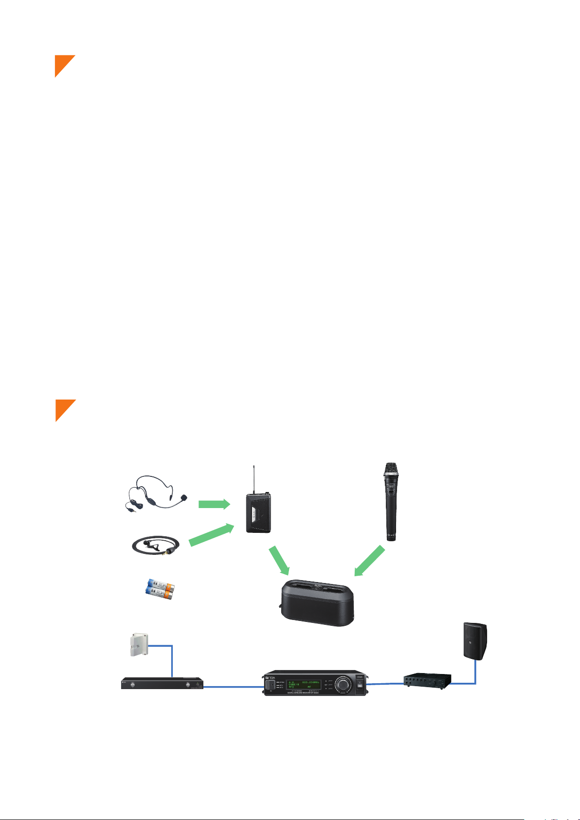
System Equipment Configuration
Headset microphone
WH-4000H
WH-4000A
Tie-clip microphone
YP-M5300
YP-M5310
Rechargeable battery
WB-2000-2
Wireless antenna
YW-4500
*
Antenna distributor
WD-5800
Digital wireless transmitter
WM-D5300 (belt-pack type)
Digital wireless receiver
WT-D5800
Battery charger
BC-2000
*
Digital wireless microphone
WM-D5200 (handheld type)
Speaker
Amplifier
*BC-2000 and WB-2000-2 are not designed for the use in the U.S. and Canada, and available in these countries.
- 1 -
Page 3
How the Digital Wireless System Works
sound reproduction.
Can function correctly
even if more undesired
signals are present as
1
2
2
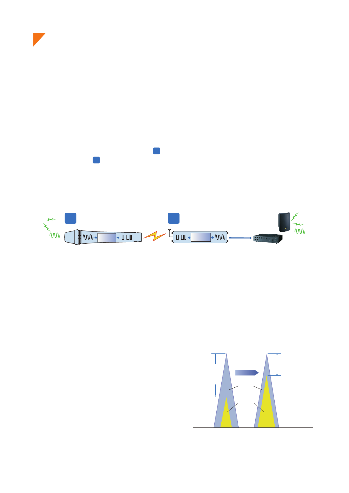
» How the Digital Wireless System Works
Signal waveforms are used to represent sound, and the state of the sound is expressed according to the
width or height of the waveform. Wireless microphones transduce the waveform of audio entering the
microphone into an electrical signal and transmit that signal to a tuner over radio waves. In this event, it is
an analog wireless system that processes the audio signal as it is in the waveform. On the other hand, it is a
digital wireless system that digitally processes the audio signal.
More specifically, in the digital system, after an analog signal (waveform) is transduced into a digital signal (a
signal simplified by binary numbers 0 and 1) and transmitted by radio, the digital signal is demodulated
into an analog signal and then the audio is output. By digitally processing and simplifying the audio
information to be transmitted, the system can have a variety of advantages, including strong immunity to
noise and maintenance of clear sound.
“Hello”
Audio
(analog)
Digital signal processing
1 2
of analog audio
Digital
modulation
Wireless microphone Wireless receiver Broadcast
Demodulation of digital
to audible analog signal
Digital
demodulation
“Hello”
Audio
(analog)
» Why are digital wireless systems resistant to interference signals?
Let’s have a look at the “D/U ratio” of analog-to-digital wireless systems. The D/U ratio refers to the ratio of the
desired (D) signal to the undesired (U) signal (unit: dB). The desired signal represents the level of that signal,
while the undesired signal represents the level of signal interference, otherwise called noise. The D/U ratio
decreases as the undesired signal increases. The D/U ratio can be considered to be a value necessary to
maintaining clear sound in a wireless system.
If a comparison is made of the necessary D/U
ratio between analog and digital wireless systems,
it is 40dB for analog systems and 20dB for digital
systems. From this, it can be seen that the digital
wireless system has an edge over the analog
wireless system by 20dB in terms of necessary
D/U ratio, indicating that the digital system can
maintain clear sound in circumstances where a lot
of undesired signals are present.
D/U ratio needs
be 40dB or more
Analog System Digital System
for clear sound
reproduction.
Desired
signal
• •
Undesired
signal
• •
D/U ration may be
over 20dB for clear
compared with
analog systems.
Spectrum Spectrum
- 2 -
Page 4
Advantages of the Digital Wireless System 1/2
Not only can the digital wireless system reduce the influence of noise, it can also maintain clear
sound quality by means of digital processing. In addition to this, there are various advantages
unique to the digital wireless system.
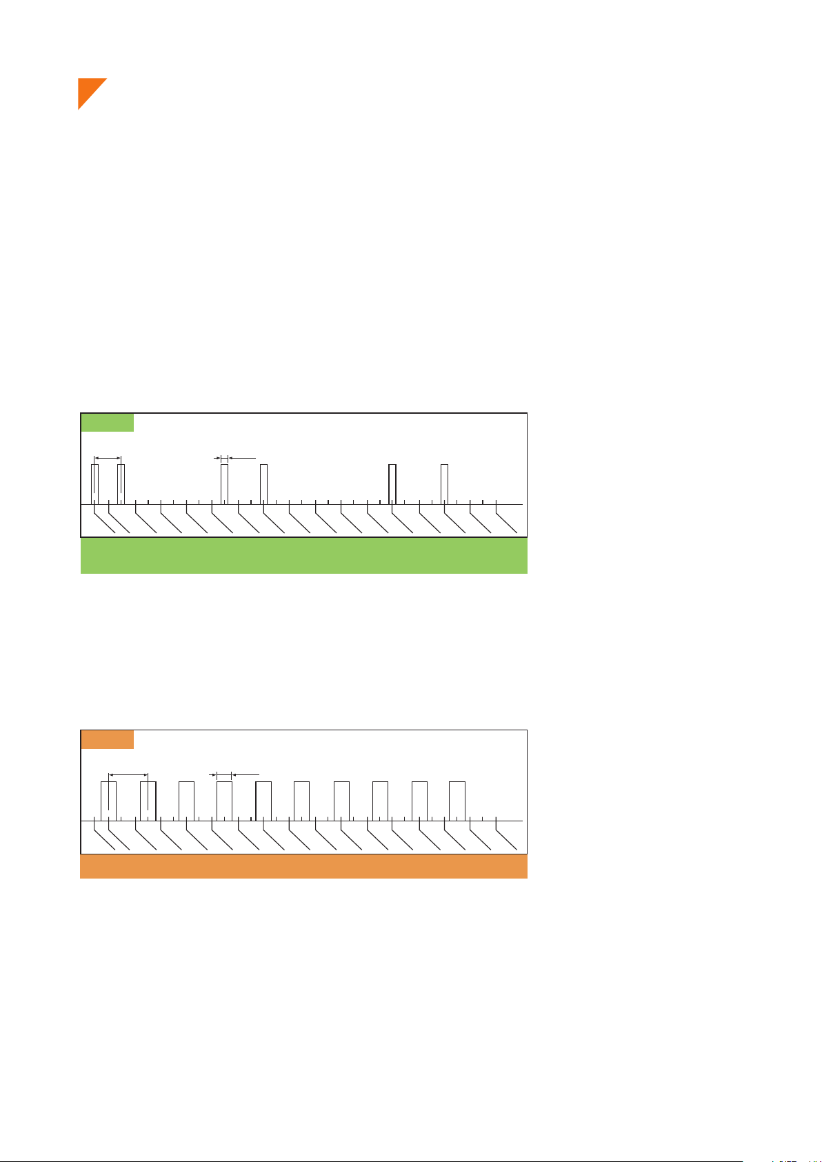
» Use of Multiple Channels in the Same Area
Since the wireless microphone makes itself a source of noise, when using multiple channels in the same
area, channels must be arranged to avoid radio interference due to intermodulation interference. In the case
of the analog wireless system, the most efficient channel arrangement is as shown in the [Analog] figure
below if the intermodulation interference of radio waves is taken into consideration. In this arrangement, the
simultaneous use of 6 channels is all it can handle per 4 MHz band.
Analog
Minimum interval
250 kHz
Occupied bandwidth
110 kHz
809.500
809.750
810.000
(MHz)
806.125
806.250
806.500
806.750
807.000
807.250
807.500
807.750
808.000
808.250
808.500
808.750
809.000
809.250
6 channels/4 MHz (channel arrangement taking intermodulation
interference into consideration)
* This is an example.
In the digital wireless system, however, since one of its features is being immune to the influence of noise,
even when the intermodulation interference occurs, individual channels are less likely to be affected by it. As
a result, equal-interval channel arrangements such as shown in the [Digital] figure below becomes possible,
allowing up to 10 channels to be used simultaneously per 4 MHz band.
Digital
Minimum interval
375 kHz
806.500
806.750
(MHz)
806.125
806.250
[10 channels/4 MHz (equal-interval channel arrangement)]
* This is an example.
807.000
Occupied bandwidth
192 kHz
807.500
807.250
807.750
808.000
808.250
808.500
808.750
809.000
809.250
809.500
809.750
810.000
» Interference Noise Muting
Analog systems are prone to generation of strange noises when exposed to radio interference. Conversely,
radio interference is muted in digital systems, so strange noises are not produced.
- 3 -
Page 5
Advantages of the Digital Wireless System 2/2
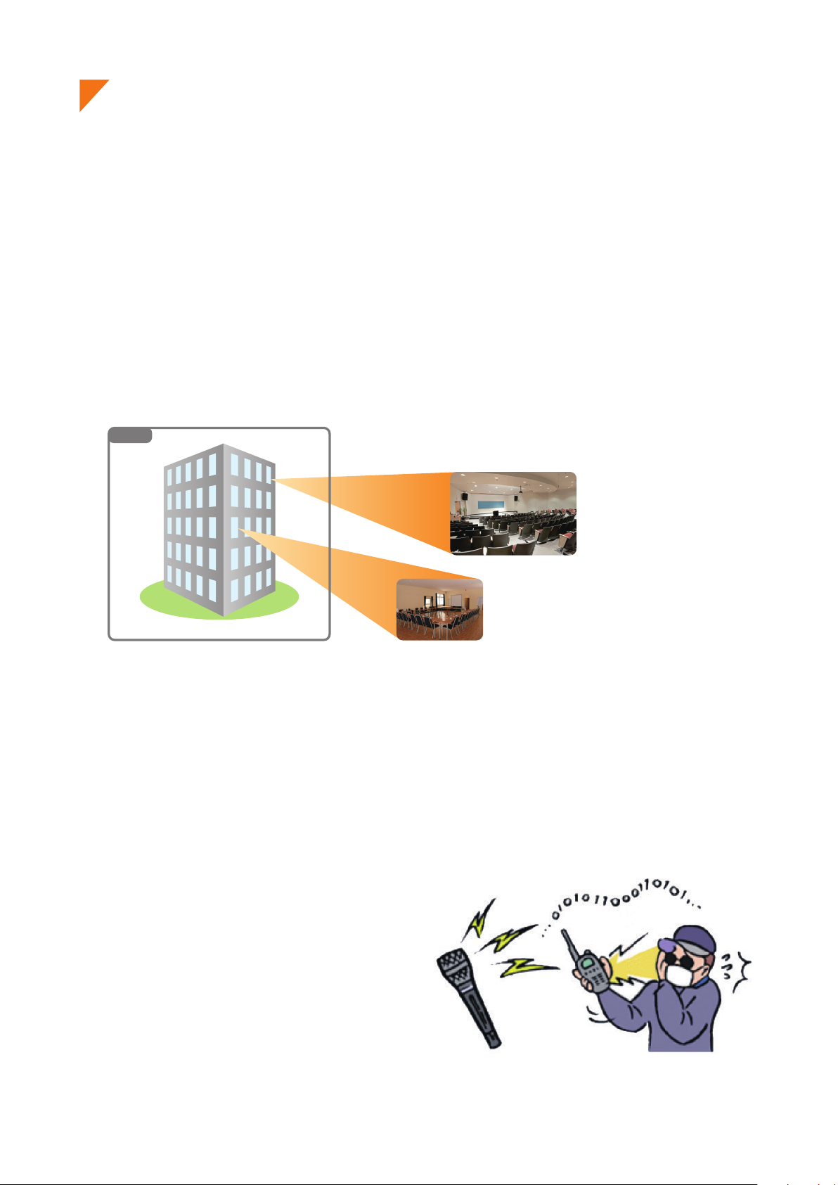
» Reuse of the Same Channel
Another advantage of the digital wireless system is that simultaneous use of multiple microphones on the
same frequency in the same area can be realized more easily because of its immunity to radio interference
and noise.
In the case of analog systems, the distance between microphones should be at least 100 meters when using
the same frequency channel in the same area to ensure 40 dB of D/U ratio. However, in the case of digital
systems, the distance can be reduced to 30 - 40 m*, making it easier to cope with even a building (area) with
multiple rooms that require multiple microphones.
*This can change depending on antenna mounting conditions or room conditions, such as the thickness or material of walls.
Area and Room
Area
Room
Room
» Improved Security
Conventional analog wireless systems transmit their audio signals through FM modulation. With this
method, it is possible that communications could be intercepted by general broadband receivers (FM radio,
etc.), causing much anxiety in terms of security. On the other hand, with digital systems, since the audio is
transmitted through digital modulation, only noise can be heard if received by a broadband receiver. This can
prevent exposure of information, leading to improvements in the security of information communication.
- 4 -
Page 6

Installation/Setting Procedures - One Room
(1) Determine the operation range.
Use within the signal reception range of
the supplied antenna. Use the supplied antenna.
Use within a wider range than that of
the supplied antenna. Use the YW-4500 external antenna.
(Installation of the YW-4500 Wireless antenna, Page 7)
(Horizontal coverage of antennas, Page 7)
(2) Determine the number of transmitters to use.
Use the supplied antenna. To Step (3)
Use the external antenna. Distribute antennas depending on the number of receivers.
(Antenna distribution, Page 8, 9)
(3) Perform frequency channel settings.
1) Select an arbitrary bank from Banks 1 – 4 at the receiver. (Frequency table, Page 10 -13)
If you need more simultaneously usable channels, then use Bank A – F.
In this case, please switch transmitter's Transmission Output to "L (1mW)".
* Banks A – F cannot be used when including existing analog wireless equipment in the system.
2) Check for idle channels using the channel scanning function.
3) Similarly, perform bank settings and idle channel assignments for the remaining receivers.
4) Set the transmitters for the same bank and frequency channels as the receivers.
(4) Need to prevent eavesdropping?
Perform encryption settings if it is necessary to prevent eavesdropping. (Encryption settings, Page 16)
(5) Conduct transmission/reception test.
Check for the presence of radio interference
When interference is detected (Radio interference countermeasures, Page 17)
(6) Optimize sound quality.
Enable automatic suppression of acoustic feedback. (FBS settings, Page 19)
Set an appropriate EQ for the microphone. (EQ Settings, Page 20)
(7) Optimize the sound volume.
Adjust the transmitter sensitivity. (Sensitivity and volume settings, Page 21)
Adjust the receiver output volume.
- 5 -
Page 7

Installation/Setting Procedures - Multiple Rooms
(1) Determine the operation range.
Use within the signal reception range of
the supplied antenna. Use the supplied antenna.
Use within a wider range than that of
the supplied antenna. Use the YW-4500 external antenna.
(Installation of the YW-4500 Wireless antenna, Page 7)
(Horizontal coverage of antennas, Page 7)
(2) Determine the number of transmitters to use.
Use the supplied antenna. To Step (3)
Use the external antenna. Distribute antennas depending on the number of receivers.
(Antenna distribution, Page 8, 9)
(3) Confirm the number of channels that can be simultaneously
used by the frequency table.
(Frequency table, Page 10 - 13)
(4) Calculate the total number of transmitters to be used simultaneously in all rooms.
The total number of transmitters is within the number of The total number of transmitters exceeds the number of
simultaneously usable channels. simultaneously usable channels.
(5) Set the frequency channel. (Setting method when using the same channel, Page 14,15)
1) Select an arbitrary bank from Banks 1 – 4 at the receiver. (Frequency table, Page 10 - 13)
If you need more simultaneously usable channels, then use Bank A – F.
In this case, please switch transmitter's Transmission Output to "L (1mW)".
* Banks A – F cannot be used when including existing analog wireless equipment in the system.
2) Check for idle channels using the channel scanning function.
3) Similarly, perform bank settings and idle channel assignments for the remaining receivers.
4) Set the transmitters for the same bank and frequency channels as the receivers.
(6) Need to prevent eavesdropping?
Perform encryption settings if it is necessary to prevent eavesdropping. (Encryption settings, Page 16)
(7) Conduct transmission/reception test.
Check for the presence of radio interference
When interference is detected (Radio interference countermeasures, Page 17)
(8) Optimi sound quality.
Enable automatic suppression of acoustic feedback. (FBS settings, Page 19)
Set an appropriate EQ for the microphone. (EQ Settings, Page 20)
(9) Optimize the sound volume.
Adjust the transmitter sensitivity. (Sensitivity and volume settings, Page 21)
Adjust the receiver output volume.
- 6 -
Page 8

Installation of the YW-4500 Wireless Antenna
Important points for selecting the mounting position of diversity antennas are
as follows:
Point 1
Mount the two antennas within 20 – 30m (outdoor applications: 40 – 50m) visible range from the microphone’s area of
intended use.
Both antennas should be within visible range from any location where the microphones are to be used. This is necessary for
ensuring optimal conditions for one antenna to receive signals when the microphone my experience the other antenna's dead
spot. In other words, the shape of the room does not matter provided that the above conditions are met. On a diagram of the
site, use a compass to draw two circles representing a radius of 20 – 30m with each antenna as the central point. If usage
locations fall within either of the two circles, such locations can be deemed to be okay.
Point 2
As a guideline, the distance between the two antennas should be 3 – 18m. Although the coverage area becomes wider
as the distance between antennas increases, this degrades the diversity effect, and signal interruption will become more
liable to occur.
If possible, locate one antenna in the direction that can be viewed from the position where the microphone is held, and the
other antenna in the opposite direction (behind the microphone holder).
Point 3
In indoor installations, as a general guideline, install antennas at a height of 2 – 4m above the floor, lest the signal be
blocked by people in the room. Keep the antennas about 30cm below the ceiling. Install the antennas so they face in the
specified directions. When making protectors, use resin or timber and do not use metallic materials.
• Avoid positioning antennas close to metallic objects wherever possible.
• Avoid mounting antennas inside a ceiling or wall.
• Select locations where the antenna can be protected from being hit and damaged by objects.
• Protect the antennas against rain water.
Horizontal coverage of antennas under optimal conditions
• YW-4500• WT-D5800 Rod Antenna
30 - 60 m
60 m or more
- 7 -
Page 9

Antenna Distribution 1/2
• Using 1 - 3 channels
Antennas can be distributed without using the WD-5800 Antenna Distributor.
audio
to mixer
• Simultaneous use of 4 channels
to mixer
• Simultaneous use of 5 – 8 channels
to mixer
audio
audio
- 8 -
Page 10

Antenna Distribution 2/2
• Simultaneous use of 9 -16 channels
to mixer
audio
to mixer
audio
to mixer
• Simultaneous use of 17 - 32 channels
Split antennas into two systems and construct a system of up to 32 channels.
to mixer
audio
to mixer
to mixer
audio
audio
to mixer
to mixer
audio
audio
audio
to mixer
to mixer
audio
audio
to mixer
audio
to mixer
audio
[NOTE] If four or more WD-5800 (available in Q3 2017) and WT-D5800 units are connected in
series, the quality of the received radio signal could deteriorate, potentially shortening transmission
distances or generating noise. To avoid this, consider using a system configuration that can
minimize the number of cascade-connected parts.
- 9 -
Page 11

Frequency Table (-C4 Version)
• Frequency table which can be used with 5000 Series analog wireless system
BANK
CHANNEL 1 2 3 4
0 794.250 794.300 794.350 794.400
1 794.600 794.650 794.700 794.750
2 795.050 795.100 795.150 795.200
3 795.600 795.650 795.700 795.750
4 796.500 796.550 796.600 796.650
5 797.700 797.750 797.800 797.850
6 799.250 799.300 799.350 799.400
7 800.900 800.950 801.000 801.050
8 801.600 801.650 801.700 801.750
9 803.350 803.400 803.450 803.500
A 804.450 804.500 804.550 804.600
B - - - C - - - D - - - E - - - F - - - -
Compatible Frequency List
*WM-D5200/D5300, WT-D5800: BANK 1 - 4
WM-4200/4300/5220/5270/5320/5225/5265/5325: BANK 1– 4
WT-4800/5800/5805: BANK 1– 4
WM-4210/4220/4310, WT-4810/5100/5810, WTU-4800: BANK 1
• When needing more channels
*Banks A - F cannot be used when including existing analog wireless equipment in the system.
BANK
CHANNEL A B C D E F
0 794.250 800.250 794.375 800.375 794.500 800.500
1 794.625 800.625 794.750 800.750 794.875 800.875
2 795.000 801.000 795.125 801.125 795.250 801.250
3 795.375 801.375 795.500 801.500 795.625 801.625
4 795.750 801.750 795.875 801.875 796.000 802.000
5 796.125 802.125 796.250 802.250 796.375 802.375
6 796.500 802.500 796.625 802.625 796.750 802.750
7 796.875 802.875 797.000 803.000 797.125 803.125
8 797.250 803.250 797.375 803.375 797.500 803.500
9 797.625 803.625 797.750 803.750 797.875 803.875
A 798.000 804.500 798.125 804.125 798.250 804.250
B 798.375 804.375 798.500 804.500 798.625 C 798.750 - 798.875 - 799.000 D 799.125 - 799.250 - 799.375 E 799.500 - 799.625 - 799.750 F 799.875 - 800.000 - 800.125 -
Compatible Frequency List
*WM-D5200/D5300, WT-D5800
- 10 -
Page 12

Frequency Table (-C7 Version)
• Frequency table which can be used with 5000 Series analog wireless system
BANK
CHANNEL 1 2 3 4
0 823.325 824.350 823.225 798.625
1 824.525 824.950 824.825 798.975
2 824.975 826.000 826.025 799.425
3 825.875 826.750 826.625 799.975
4 826.925 828.250 828.625 800.625
5 827.675 828.700 829.625 801.525
6 829.175 829.600 831.025 802.975
7 829.775 830.800 831.825 804.725
8 823.425 824.425 823.175 806.625
9 824.625 825.025 825.175 809.275
A 825.075 826.075 825.875 810.375
B 825.975 826.825 826.775 813.125
C 827.025 828.325 828.975 816.225
D 827.775 828.775 830.075 820.425
E 829.275 829.675 831.375 822.625
F 829.875 830.875 831.875 827.475
Compatible Frequency List
*WM-D5200/D5300, WT-D5800: BANK 1 - 4
WM-4200/4300/5220/5270/5320/5225/5265/5325: BANK 1– 4
WT-4800/5800/5805: BANK 1– 4
WM-4210/4220/4310, WT-4810/5100/5810, WTU-4800: BANK 1
• When needing more channels
*Banks A - F cannot be used when including existing analog wireless equipment in the system.
BANK
CHANNEL A B C D E F
0 823.250
1 823.625
2
3
4
5
6
7
8
9
A
B
C
D
E
F
Compatible Frequency List
*WM-D5200/D5300, WT-D5800
824.000 830.000 824.125 830.125 824.250 830.250
824.375 830.375 824.500 830.500 824.625 830.625
824.750 830.750 824.875 830.875 825.000 831.000
825.125 831.125 825.250 831.250 825.375 831.375
825.500 831.500 825.625 831.625 825.750 831.750
825.875 831.875 826.000 - 826.125 -
826.250 - 826.375 - 826.500 -
826.625 - 826.750 - 826.875 -
827.000
827.375 - 827.500 - 827.625
827.750
828.125
828.500
828.875
829.250 823.375 829.375 823.500 829.500
829.625 823.750 829.750 823.875 829.875
-
-
-
-
-
827.125 - 827.250 -
827.875
828.250
828.625
829.000
-
-
-
-
828.000
828.375
828.750
829.125
-
-
-
-
-
- 11 -
Page 13

Frequency Table (-G1 Version)
• Frequency table which can be used with 5000 Series analog wireless system
BANK
CHANNEL 1 2 3 4
0 606.725
1
2
3
4
5
6
7
8
9
A
B
C
D
E
F
Compatible Frequency List
*WM-D5200/D5300, WT-D5800: BANK 1 - 4
WM-4200/4300/5220/5270/5320/5225/5265/5325: BANK 1– 4
WT-4800/5800/5805: BANK 1– 4
WM-4210/4220/4310, WT-4810/5100/5810, WTU-4800: BANK 1
824.525 824.950 824.825 798.975
607.725 607.750 607.775 607.800
608.375 608.400 608.425 608.450
609.125 609.150 609.175 609.200
610.425 610.450 610.475 610.500
611.275 611.300 611.325 611.350
613.025 613.050 613.075 613.100
615.275 615.300 615.325 615.350
616.375 616.400 616.425 616.450
619.475 619.500 619.525 619.550
621.975 622.000 622.025 622.050
626.275 626.300 626.325 626.350
630.725 630.750 630.775 630.800
634.175 634.200 634.225 634.250
635.675 635.700 635.725 635.750
606.750 606.775 606.800
• When needing more channels
*Banks A - E cannot be used when including existing analog wireless equipment in the system.
BANK
CHANNEL A B C D E
0 606.725
1
2
3
4
5
6
7
8
9
A
B
C
D
E
F
Compatible Frequency List
*WM-D5200/D5300, WT-D5800
607.100 613.100 619.100 625.100 631.100
607.475 613.475 619.475 625.475 631.475
607.850 613.850 619.850 625.850 631.850
608.225 614.225 620.225 626.225 632.225
608.600 614.600 620.600 626.600 632.600
608.975 614.975 620.975 626.975 632.975
609.350 615.350 621.350 627.350 633.350
609.725 615.725 621.725 627.725 633.725
610.100 616.100 622.100 628.100 634.100
610.475
610.850 616.850 622.850 628.850 634.850
611.225
611.600
611.975
612.350
612.725 618.725 624.725 630.725
616.475
617.225
617.600
617.975
618.350
622.475 628.475 634.475
623.225
623.600
623.975
624.350
629.225
629.600
629.975
630.350
635.225
635.600
-
-
- 12 -
Page 14

Frequency Table (-H1 Version)
• Frequency table which can be used with 5000 Series analog wireless system
BANK
CHANNEL 1 2 3 4
0
1
2
3
4
5
6
7
8
9
A
B
C
D
E
F
Compatible Frequency List
*WM-D5200/D5300, WT-D5800: BANK 1 - 4
WM-4200/4300/5220/5270/5320/5225/5265/5325: BANK 1– 4
WT-4800/5800/5805: BANK 1– 4
WM-4210/4220/4310, WT-4810/5100/5810, WTU-4800: BANK 1
578.600 578.625 578.650 579.100
579.050 579.075 579.100 579.550
579.600 579.625 579.650 580.100
580.250 580.275 580.300 580.750
581.000 581.025 581.050 581.500
582.100 582.125 582.150 582.600
583.600 583.625 583.650 584.100
584.900 584.925 584.950 585.400
585.750 585.775 585.800 586.250
587.800 590.025 589.050 590.500
592.150 593.775 591.750 592.800
594.400 596.075 596.600 594.850
598.200 598.125 598.350 598.000
601.450 601.275 600.400 599.750
604.150 603.025 602.650 602.450
605.900 605.725 605.600 605.700
• When needing more channels
*Banks A - E cannot be used when including existing analog wireless equipment in the system.
BANK
CHANNEL A B C D E
0
1
2
3
4
5
6
7
8
9
A
B
C
D
E
F
Compatible Frequency List
*WM-D5200/D5300, WT-D5800
576.250 582.250 588.250 594.250 600.250
576.625 582.625 588.625 594.625 600.625
577.000 583.000 589.000 595.000 601.000
577.375 583.375 589.375 595.375 601.375
577.750 583.750 589.750 595.750 601.750
578.125 584.125 590.125 596.125 602.125
578.500 584.500 590.500 596.500 602.500
578.875 584.875 590.875 596.875 602.875
579.250 585.250 591.250 597.250 603.250
579.625 585.625 591.625 597.625 603.625
580.000
586.000
592.000 598.000 604.000
580.375 586.375 592.375 598.375 604.375
580.750
581.125
581.500
581.875
586.750
587.125
587.500
587.875
592.750
593.125
593.500
593.875
598.750
599.125
599.500
599.875
604.750
605.125
605.500
-
- 13 -
Page 15

Procedure for Reusing the Same Frequency 1/2
When using transmitters in numbers greater than the number of simultaneously
usable channels and in close proximity to each other, microphones operating on the
same frequency can be used simultaneously by utilizing their digital characteristics.
Note, however, that the same frequency cannot be used in the same room.
1. Make channel plans
• C band: Searches for channels in two banks including the currently-set bank and displays idle channels.
Combinations of scanned banks are as follows:
When Bank A or B is currently set a Searches for and displays idle channels in Banks A and B.
When Bank C or D is currently set a Searches for and displays idle channels in Banks C and D.
When Bank E or F is currently set a Searches for and displays idle channels in Banks E and F.
• G band: Searches for all bank channels in the dedicated digital plan, and displays idle channels.
operating on the same frequency from being too close to each other.
1) Referring to the Frequency Table, select an arbitrary bank from A to F.
2) Scan receiver channels.
3) Assign idle channels to multiple rooms as shown in the following examples to prevent channels
[Example] Same floor or same location on each floor.
Bank A-9
Bank A-9
Bank A-10
D/U ratio: 20dB
Bank A-10
Bank A-1
Bank A-1
Bank A-3
Bank A-3
Bank A-4
Bank A-4
Bank A-5
Bank A-5
Bank A-1
Bank A-1
Bank A-2
Bank A-2
Bank A-3
Bank A-1
Bank A-1
Bank A-2
Bank A-2
‐ Keep channels using the same frequency as far away from each other as possible.
If used on the same floor, keep them at least two rooms apart.
‐ Set the wireless microphone’s transmission output to “L.”
‐ Adjust the antenna attenuator.
Bank A-3
Bank A-4
Bank A-4
Bank A-5
Bank A-5
D/U ratio: 20dB
Bank A-6
Bank A-6
Bank A-7
Bank A-7
Bank A-8
Bank A-8
Bank A-9
Bank A-9
Bank A-10
Bank A-10
Bank A-1
Bank A-1
[Example] Multiple rooms are adjacent to each other on both upper and lower floors in facilities like rental
conference rooms and schools. There is a high possibility that the frequencies being used in the
room may also be able to be used in rooms .
Bank A-1Bank A-1
- 14 -
Page 16

Procedure for Reusing the Same Frequency 2/2
Figure c. If different codes are set in Area 1 and Area 2, mistaken
reception will not occur even if power to the microphone
for either area is turned off. (Since microphones in both
2. Use "Code" (recommended)
This function prevents interference between channels sharing the same frequency. By performing Code settings,
receivers and transmitters can be paired, muting radio signals on the same frequency that may exist in the surrounding
area. Code setting is effective when the encryption function is not set.
Figure a. Even if the code is the same, if the power for both microphones
is ON, radio interference will not occur. (Since the stronger radio
signal takes precedence, only the microphone within the
immediate area is reproduced.)
Room 1 Room 2
MIC 1
(Code 1)
MIC 2
(Code 1)
Receiver 1
(Code 1)
Reproduces MIC 1 audio. Reproduces MIC 2 audio.
Receiver 2
(Code 1)
Code settings
solve these
areas differ in code, audio is muted.)
Room 1 Room 2
MIC 1
(Code 1)
MIC 2
(Code 2)
problems.
Figure b. If power to either area is turned off when Figure a conditions
exist, Receiver 1 may mistakenly receive MIC 2 audio. (Since
the code is the same, it would be impossible to distinguish
between MIC 1 and MIC 2.)
Room 1 Room 2
MIC 1
(Code 1)
Receiver 1
(Code 1)
Reproduces MIC 2 audio.
(Mistaken reception)
MIC 2
(Code 1)
Receiver 2
(Code 1)
Reproduces MIC 2 audio.
Receiver 1
(Code 1)
Muted
Receiver 2
(Code 2)
Reproduces MIC 2 audio.
» Code setting procedures
Hold down the “SET” key for 2 seconds or more. Select “CODE” and press “SET” Select an arbitrary number
MENU
>CODE
WT-D5800
Selected CODE
Set the same code for the transmitter to be paired.
SET CODE
A
– 1 8 8 8 . 8 2 5 HM z
CODE: 1
A
R F A F
B
Code setting switch
CODE
H
L
1
2
Screwdriver
(accessory)
NOTE: Since the encryption function, which enhances security, also requires pairing of a transmitter with a
receiver, code setting is unnecessary if the encryption function is used.
- 15 -
Page 17

Encryption Function Settings
Exposure of important information can be prevented by pairing a receiver with
a transmitter by TOA’s proprietary security IDs.
» Engryption setting procedures
1) Enable receiver’s encryption function.
Hold down the “SET” key for 2 seconds or more. Select ENCRYPTION from the menu Select “ON”
MENU
>ENCRYPTION
WT-D5800
2) Pair the receiver with a transmitter.
Select PAIRING from the menu
MENU
>PAIRING
Switch on the transmitter while holding down the “Encryption” setting switch.
Hold and switch on.
HL
SET
MENU
>HOLD THE SET KEY
HL
SET ENCRYPTION
3 ON
AF PEAK
A – 1 8 8 8 . 8 2 5 HM z
ANT A
ANT B
A
R F A F
B
If encryption function is achieved, the
“ANT A/B” indication and the lock icon
lights red.
0-36dBμV 10 30 100 300 500 -27 -18 -9
Press and hold “SET” till the “SUCCESS” is displayed.
PAIRING PROCESS
RECEIVING
PAIRING PROCESS
SUCCESS
If pairing is achieved, the “ANT A/B” indication lights green and
the transmitter’s “Encryption” light also lights.
green
AF PEAK
A – 1 8 8 8 . 8 2 5 HM z
ANT A
ANT B
A
R F A F
B
“Encryption” light
0-36dBμV 10 30 100 300 500 -27 -18 -9
- 16 -
Page 18

Interference Countermeasures
Order of Actions (Action Flowchart)
Change bank/channel numbers to those of idle channels.
(See p. 10 - 13)
Check reception indicators.
Any interference?
Ye s
Perform antenna attenuator settings to limit service area.
(See p. 18, “Antenna Attenuator”.)
Check reception indicators.
Any interference?
Ye s
Is the encryption
function set to “ON”?
Note
Most interference can be avoided by operations
above. If interference is still encountered, select
channel having relatively less interference, then
continue following operations.
No
No
Use as is.
Use as is.
Perform code setting.
(See p.15, “Code setting.”)
Perform pairing setting. (See p. 16, “Encryption setting.”)
Check reception indicators.
Any interference?
Ye s
When radio interference is still encountered, consult shop
from where unit was purchased.
No
- 17 -
Use as is.
Page 19

Antenna Attenuator
» Antenna Attenuator Function
This function decreases the antenna reception sensitivity so as to minimize reception of distant
interference radio signals.
Undesired
Undesired
•When to use this function
Use this function when radio interference or signal interruption caused by the interference of other systems
intermittently occurs.
Note: Since the use of an attenuator shortens the transmission distance and reduces the range of the usable
area, ensure that the microphone can be used without signal interruption in the intended usage area after
performing settings.
The attenuator can effectively reduce interference signals if they are relatively weak. The most effective results
may not be obtained when interference signals are strong (i.e. when audio interference constantly occurs).
•Proper use of two attenuators
Use either the WT-D5800 or YW-4500 attenuator to attenuate the reception sensitivity by 10dB. The WT-
D5800 may be more convenient as it allows settings by hand.
Since the attenuation of both the YW-4500 and WT-D5800 attenuators are added together, when
wishing to attenuate reception sensitivity by at least 10dB, use both attenuators in combination.
(This is a rare case, though.)
- 18 -
Page 20

FBS Setting
» What is the feedback suppressor function?
It is a function that the built-in feedback suppressor filter automatically works to suppress acoustic feedback
when the feedback occurs.
Level
Feedback suppressor
filter
Feedback
Frequency
frequency
» What is the FBS built into the WT-D5800?
Use this function when increases in the receiving wireless microphone’s sound volume tend to generate
acoustic feedback and reduce speech clarity or make it impossible to achieve the necessary sound volume
for broadcast.
Hold down the “SET” key for 2 seconds or more. Select “FBS” and press “SET”
MENU
>FBS
WT-D5800
SET FBS
3 ON
A – 1 8 8 8 . 8 2 5 HM z
A
R F A F
B
“FBS” appears
FBS
NOTE: Acoustic feedback, or howling, is generated when sound output from a speaker reenters the
microphone. Before using this function, check to see if the microphone and speaker are positioned too close
to each other, or if the sound volume is louder than necessary.
In circumstances where feedback is especially liable to occur, the most effective results may not be
obtainable, or sound quality may vary greatly.
- 19 -
Page 21

EQ Setting (Recommended)
» What is the microphone EQ built into the WT-D5800?
This function optimizes audio characteristics for each model of handheld wireless microphone or any
microphone connected to the belt-pack transmitter.
Select the model number of the microphone to use, and perform settings in EQ setting mode.
Hold down the “SET” key for 2 seconds or more. Options
WT-D5800
MENU
>EQ PRESET
SET EQ PRESET
3 OFF
SET EQ PRESET
3 WM-D5200
SET EQ PRESET
3 YP-M5300
SET EQ PRESET
3 YP-M5310
SET EQ PRESET
3 WH-4000A
SET EQ PRESET
3 WH-4000H
SET EQ PRESET
3 EXIT
NOTE: This function is set to OFF by default.
Set the “Microphone EQ” to OFF when the corresponding model number is not shown in the display of the
EQ setting mode.
- 20 -
Page 22

Optimizing Sound Volume
(1) Set the receiver’s volume control to the 2 o’clock position.
For current TOA wireless receivers with the volume
control located on the front panel, the 2 o’clock position
(scale 7) is the volume control position that minimizes
sound distortion until the maximum input sound pressure
is applied to the microphone. From that position to the
maximum volume position, a gain of approximately 10dB
is made available as an allowance when turning up the
volume.
(2) Set the transmitter’s (microphone’s) sensitivity to “H” or “L” depending on whether the
volume is insufficient or noise is detected at normal sound volume, or if distortion is not
noticeable when speaking in a loud voice.n to the maximum volume position, a gain of
approximately 10dB is made available as an allowance when turning up the volume.
Microphone sensitivity can be set to "0 dB (H)" or "-10 dB (L)".
HL
HL
(3) Adjust the input level of the amplifier or mixer to an appropriate sound volume for use
under normal conditions.
- 21 -
Page 23

- 22 -
Page 24

TOA Corporation
www.toa.jp
Specifications are subject to change without notice. (201804) 833-61-100-36-04
 Loading...