

Page 1
INSTRUCTION MANUAL
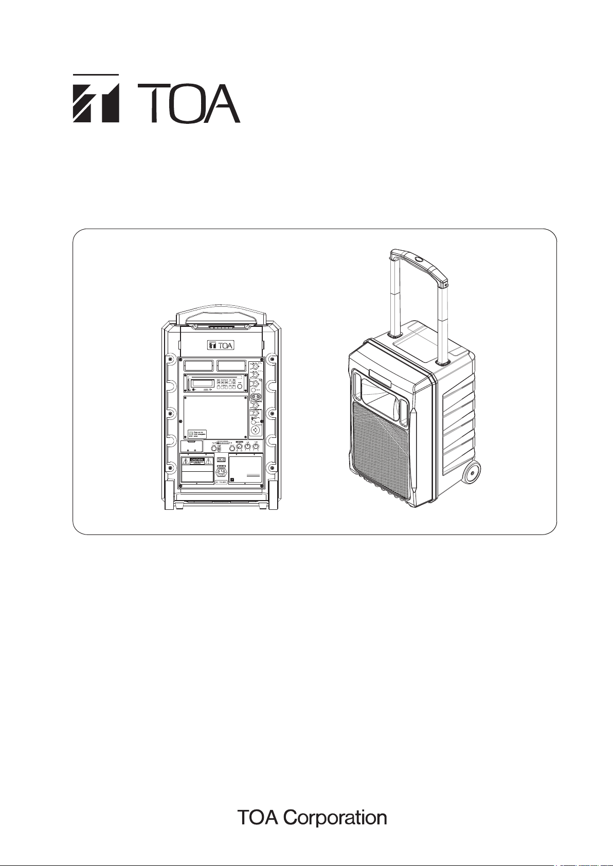
PORTABLE AMPLIFIER
PORTABLE AMPLIFIER
Model
WA-S110SD-AS
Rated Output
Caution : To reduce the risk of electric shock, do not remove cover
( or back). No user-serviceable parts inside. Refer servicing
to qualified service personnel.
Warning : To reduce the risk of fire or electric shock, do not expose
the appliance to rain or moisture.
Notice 1 : If this machine won’t be used for more than 1 month or the
indication of battery power display shows red, Please
recharge the battery immediately above 8 hours until space
indication display turns green means fully charged status.
Notice 2 : Please switch off the power if no need to use. If the machine
cut off the power automatically, please recharge the battery
within 3 days, otherwise it will cause battery damage.
Notice 3 : Please use the original dealer battery.
AC Input Source
TOA Corporation
TOA Corporation
MADE IN INDONESIA
70W (RMS)
100-240V AC ~ 50/60Hz
, JAPAN
WA-Z110SD-AS
TABLE OF CONTENTS
1. SAFETY PRECAUTIONS
2. GENERAL DESCRIPTION
3. NOMENCLATURE AND FUNCTIONS
4. MASTER PANEL CONTROL
5. POWER AND VOLUME IDENTIFICATION
6. AUDIO MUSIC PLAYER
7. WIRELESS RECEIVER MODULE ............... 7
7.1. UHF PLL Non-Diversity receiver module 7
7.2. Wireless Receiver Installation ............... 7
Thank you for purchasing TOA's Portable Amplifier.
Please carefully follow the instructions in this manual to ensure long, trouble-free use of your equipment.
............................ 2
........................... 3
......... 4
....................... 5
.. 5
............................... 6
8. TRANSMITTERS
........................................ 8
8.1. WM-Z100H Wireless Handheld microphone
WM-Z100L Wireless Lavaliere microphone
8.2.
9. REPLACEMENT OF BATTERY
10. WARNING
................................................ 9
................ 9
11. SPECIFICATIONS ................................. 10
11.1. General Specifications
11.2. Microphone Specifications
11.3. Channel Specifications
................... 10
............. 11
................... 11
8
8
Page 2

1. SAFETY PRECAUTIONS
•
Be sure to read the instruction in this section carefully before use.
•
Make sure to observe the instructions in this manual as conventions of safety symbols and messages
regarded as very important precautions are included.
•
We also recommend you keep this instruction manual handy for future reference.
Safety Symbol and Message Conventions
Safety symbols and messages described below are used in this manual to prevent bodily injury and property
damage which could result from mishandling. Before operating your product, read this manual first and
understand the safety symbols and messages so you are thoroughly aware of the potential safety hazards.
WARNING
When Installing the Unit
Do not expose the unit to rain or an environment where it may be splashed by water or other liquids, as
doing so may result in fire or electric shock.
Use the unit only with the voltage specified on the unit. Using a voltage higher than that which is specified
doing so may result in fire or electric shock.
Do not cut, kink, otherwise damage nor modify the power supply cord. In addition, avoid using the power
cord in close proximity to heaters, and never place heavy objects -- including the unit itself -- on the power
cord, as doing so may result in fire or electric shock.
Avoid installing or mounting the unit in unstable locations, such as on rickety table or a slanted surface
Doing so may result in the unit falling down and causing personal injury and/or property damage.
To prevent lightning strikes, install the unit at least five meters away from a lightning rod, and yet within the
protective range (angle of 45° ) of the lightning conductor. Lightning strikes may cause a fire, electric shock
or personal injury.
When the Unit is in Use
Indicates a potentially hazardous situation which, if mishandled, could
result in death or serious personal injury.
Should the following irregularity be found during use, immediately switch off the power, disconnect the power
supply plug from the AC outlet and contact your nearest TOA dealer. Make no further attempt to operate the
unit in this condition as this may cause fire or electric shock.
If you detect smoke or a strange smell coming from the unit
If water or any metallic object gets into the unit
If the unit falls, or the unit case breaks
the power supply cord is damaged (exposure of the core, disconnection, etc)
Do not place cups,bowls or other containers of liquid or metallic objects on top of the unit. If they accidentally
spill into the unit, this may cause a fire or electric shock.
Do not insert nor drop metallic object or flammable materials in the ventilation slots of the unit’s cover, as this
may result in fire or electric shock.
Do not touch a plug during thunder and lightning, as this may result in electric shock.
To prevent a fire or electric shock, never open nor remove the unit case as there are high voltage
component inside the unit. In addition, modifying the internal parts or circuit may cause the unit to be against
the regulations in your country.
Refer all servicing to your nearest TOA dealer.
2
Page 3

Indicates a potentially hazardous situation which, if mishandled, could
CAUTION
When Installing the Unit
Never plug in nor remove the power supply plug with wet hands, as doing so may cause electric shock.
When unplugging the power supply cord, be sure to grasp the power supply plug, never pull on the cord itself.
Operating the unit with a damaged power supply cord may cause a fire or electric shock.
When moving the unit, be sure to remove its power supply cord from the wall outlet. Moving the unit with the
power cord connected to the outlet may cause damage to the power cord, resulting in fire or electric shock.
when removing the power cord, be sure to hold its plug to pull.
Avoid installing the unit in humid or dusty locations, in locations exposed to the direct sunlight, near the
heaters, or in locations generating sooty smoke or steam as doing otherwise may result in fire or electric shock.
When the Unit is in Use
Make sure the volume control is set to minimum position before power is switched on. Loud noise produced
at high volume when power is switched on can impair hearing.
result in moderate or minor personal injury, and/or property damage.
Do not place heavy object on the unit as this may cause it to fall or break which may result in personal
injury and/or property damage. In addition, the object itself may fall off and cause injury and/or damage.
Do not stand or sit on, nor hang down from the unit as this may cause it to fall down or drop, resulting in
personal injury and/or property damage.
When the unit is not in use for 10 days or more, or when the AC power is used for operating the unit, be
sure to take the batteries out of the unit because battery leakage may cause a fire, personal injury, or
contamination of environment.
Switch off the power, and unplug the power supply plug from the AC outlet for safety purposes when
cleaning or leaving the unit unused for 10 days or more. Doing otherwise may cause a fire or electric shock.
Make sure to observe the following handling precautions so that a fire or personal injury does not result from
leakage or explosion of the battery.
Do not short, disassemble, heat nor put the battery into a fire.
Avoid using both new and old batteries together.
Do not solder a battery directly.
Be sure to use the specified type of batteries.
Note correct polarity (positive and negative orientation) when inserting a battery in the unit.
Avoid locations exposed to the direct sunlight, high temperature and high humidity when storing batteries.
Do not use trolley on ragged ground to avoid any damage.
2. GENERAL DESCRIPTION
TOA’s WA-Z110SD series are a portable amplifier that has an elegant design, durable and water-resistant case.
It offers reliable performance, clear, powerful sound, and is simple to operate. Equipped with an audio music
player, Music can be played from CD, USB or SD / MMC Card. It has the option of installing up to 2 UHF
wireless microphone receiver. Wheels are fitted for moving it around effortlessly. The unit has an operating
duration of 3 - 9 hours, depending on the volume.
3
Page 4

3. NOMENCLATURE AND FUNCTIONS
1
14A
560mm(h)
Caution : To reduce the risk of electric shock, do not remove cover
( or back). No user-serviceable parts inside. Refer servicing
to qualified service personnel.
Warning : To reduce the risk of fire or electric shock, do not expose
the appliance to rain or moisture.
Notice 1 : If this machine won’t be used for more than 1 month or the
indication of battery power display shows red, Please
recharge the battery immediately above 8 hours until space
indication display turns green means fully charged status.
Notice 2 : Please switch off the power if no need to use. If the machine
cut off the power automatically, please recharge the battery
within 3 days, otherwise it will cause battery damage.
Notice 3 : Please use the original dealer battery.
330mm(w)
PORTABLE AMPLIFIER
Model
WA-Z100SD-AS
Daya keluaran
70W (RMS)
Tegangan AC
100-240V AC ~ 50/60Hz
TOA Corporation
MADE IN INDONESIA
11
510mm(h)
13
12
14B
4A
8
, JAPAN
9
10
6
2
3
4B
5
7
310mm(d)
1. Carry Handle : To pull or retract the carry handle, press one touch button.
2. Rear Cover : Fixed related operational unit with audio accessories, such as CD player and batteries.
3. Front Cover : Speaker with fixed grill net.
4. Loudspeaker : (4A) 1” tweeter
(4B) 10” Woofer
5. Wheel : For moving this unit.
6. Grilled Net : To protect the speaker.
7. Tripod Socket : For use with opional speaker stand ST-34B.
8. Power On/Off : [ − ] On, power start; [ O ] Off power off, please turn off power to avoid consuming battery
when not in use.
9. AC Power Input : Comply with international voltage 90V-264V.
10. Lead Acid Battery : Instruction for changing battery : Take out 3 pieces of screws and remove batteries
from main panel board.
Please note to follow the correct operation in order to avoid causing damage to battery.
(Positive-red line with red line terminal; negative-black line with black line terminal)
11. The Storage Box : A storage space for microphone, remote control, and AC power cord.
12. Recharging box for Microphone’s battery : Simultaneously charge 4 pieces of 1.2V / 1300mA~2500mA
rechargeable batteries for microphone, red light means charging, green continuous light means full load
charged.
Attention! Only use rechargeable batteries Nickel-Metal Hybride (Ni-MH) only.
13. Wireless Receiver compartment for WTU-Z100 (optional).
Ni-MH
14. (14A) Rear infrared for remote control.
(14B) Front infrared for remote control.
4
Page 5

4. MASTER PANEL CONTROL
1
1. CD VOL : Volume control with on/off.
2. TAPE VOL (Not in use).
3. Line in VOL : Volume control for external audio input.
2
4. Phone jack/RCA Audio Line in : To amplify external
audio inputs like CD, DVD.
3
5. Digital Echo volume control.
6. Volume control for wired Microphone.
4
7. Wireless Microphone priority switch.
8. Phone jack for Wired Microphone input.
9. Phone jack & XLR jack for MIC.
5
6
7
8
9
5. POWER AND VOLUME IDENTIFICATION
2
1
3 4 5
1. Extension speaker : connect to external speaker (4-8 Ω /over 50W rated input)
2. DC IN 24V/3A : connect to external power.
3. Battery electricity display.
When not connected with power cord, the duration of operation for speaking mode is around 3~9 hours
hours (depending on volume). When the electricity display indicator is lit at PW-LOW, it means battery
is low, please charge the battery right away and switch off the power. Flashing green light means the
battery is charging. Charging time is around 6 - 8 hours. Solid green in display indicator means full
battery power.
4. Mix out : Connect with wireless transmitter or PA broadcasting system.
5. Main VOL.
6. Bass : Bass control of microphone and music, L = Cut , H = Boost.
7. Treble : Treble control of microphone and music, L = Cut , H = Boost.
6
7
5
Page 6

6. AUDIO MUSIC PLAYER
19
12
13
10
11
12A345
6789
2C
1
14
8
6
17
POWER
FIND
0
16
FUNC
vol- vol+
5
2B
7
3
15
4
9
18
1. POWER : In power OFF mode, press this key to switch ON the power.
In power ON mode, press this key for more than 2 sec. to switch OFF the power.
2. (2A) STOP/EJECT : Press to stop playing CD/USB/SDCard and press again to eject disk.
(2B) STOP : Press to stop playing (CD/USB/SDCard).
(2C) EJECT : press to eject disk.
3. FIND : In MP3 mode : Press this key once FILE search mode changed. Press this key twice ALBUM search
mode changed. If press this key long time once track is displayed. press twice ID3 TAG is displayed.
4. CUE/UP : Press to next track number.
Continued pressed, fast forward during play/pause when pressed for more than 0.7 sec.
REV/DOWN : Press to previous track number.
Continued pressed, fast reverse during play/pause when pressed for more than 0.7sec.
5. PLAY/PAUSE : Press once to start playing, press again to pause.
6. REPEAT :
(In MP3 mode and in USB mode) If this key is pressed, PLAY mode is changed cyclically as shown below.
PLAY ALL RANDOM REPEAT TRACK REPEAT FOLDER REPEAT ALL RANDOM REPEAT
PLAY ALL
In CD mode if this key is pressed, PLAY mode is changed cyclically as shown below.
PLAY ALL RANDOM REPEAT TRACK REPEAT ALL RANDOM REPEAT PLAY ALL
7. PROG : Press the PROG button then select a track by pressing the CUE / REV, for once making of
programming,
the maximum limit to 99 election programming, and terminated by pressing PROG.
Then press PLAY to start.
Set to programming mode. In programming mode, all program is cleared when [STOP] key is pressed.
8. FOLDER-DOWN: In stop mode: Skip the starting play folder to previous folder during stop mode, cyclic to the
last folder if it is in the first folder. In normal play mode: Skip the playing file to the previous folder’s first file.
FOLDER-UP: In stop mode: Skip the starting play folder to next folder during stop mode, cyclic to the first
folder if it is in the last folder. In normal play mode : Skip the playing file to the next folder’s first file.
9. FUNC : Press to change cyclically as shown : CD USB CARD.
10. LCD DISPLAY : Display CD status including track number and playing time.
11. USB Connector : Insert the USB ( Support up to 32GB ).
12. IR INFRARED : Picks up signal from the remote control.
13. SD/MMC CARD Connector : Accepts SD Card and MMC Card ( Support up to 32GB ).
14. 0~9 : Use these keys to select the track.
SD Card
15. ESP : In CD mode, Press “ESP” key.
The ESP display is lit and the set is in electronic anti-shock state. The electronic anti shock time is
about 40 seconds. Press “ESP” key again to cancel the ESP function.
16. Display : When playing a MP3 CD, and key is pressed, the LCD display will be changed cyclically as shown
below : track number and playing time total number of songs name of the playing song total
number of folder and total number of songs.
17. MUTE : In playing mode, press this key to mute, press again to recovery.
18. VOL + : When this key is pressed, the volume will increase by 1dB per step, the max. volume is 30dB.
VOL - : When this key is pressed, the volume will decrease by 1dB per step, the min. volume is 0B.
19. Slot to insert the CD.
66
Page 7

7. WIRELESS RECEIVER MODULE
7.1. UHF PLL Non-Diversity receiver module
WTU-Z100 (Optional)
1 3
2
4
5 6
1. RA Signal Indicator : The yellow LED RA lights up when wireless audio signal is being received and
transmitted.
2. LED display : When selecting channels, the selected channel is shown on the display.
3. AF Signal Indicator: The red LED AF lights up when microphone signal is being transmitted and received
when microphone is turned on.
4. Channel selector : Press up and down for 16 user selectable channels.
5. Power ON/OFF Indicator : Red LED lights up when power is on.
6. Power ON/OFF /Volume Knob : Adjust by turning clockwise to switch on power and to increase
microphone volume. Power is switched off when knob is turned to minimum.
7.2. Wireless Receiver Installation
Blank panel
Screw
Hex. wrench
Wireless receiver
Screw
Hex. wrench
1. Please switch off power before installation.
2. Unscrew the screws from the blank panel with the hex head wrench provided and
remove the blank panel.
3. Slot the wireless receiver into the compartment completely.
4. Screw back the screws tightly.
5. Installation is done correctly when the equipment is powered on and the LED indicators
on the wireless receiver lights up.
7
Page 8

8. TRANSMITTERS
8.1. WM-Z100H Wireless Handheld microphone
1. Steel grille : Protect capsule from any damage.
2. Aluminium neck ring : logo printing and fixed top and capsule.
3. Battery compartment : 1.5V x 2 pcs or 1.2V x 2 pcs
Remove the batteries when not in use for long period of time.
4. Channel switch from 1 to 16.
5. Battery indicator : This red light indicator flashes when the
batteries are almost out of power.
6. Power switch on/off : Control microphone power.
Note :
WM-Z100H is an optional item and is packaged
with WTU-Z100 wireless receiver as a set.
Set Model: WS-Z100H
8.2. WM-Z100L Wireless Lavaliere microphone
1
2
3
4
5
6
WM-Z100H
12345
7
BODY PACK
TRANSMITTER
6
WM-Z100L
1. External antenna jack : 1/4 for antenna input jack.
2. Power indicator : The red light indicator will flash once when it is turned on.
The red light indicator will be solid red when the batteries are almost out of power.
3. Mini XLR jack.
4. Volume control : Adjust the volume by turning clockwise.
5. Power switch : Power on / power off.
6. Channel selector from 1 to 16.
7. Buckle is fixed with a screw so that it can conveniently clip on the belt comfortably.
8. Buckle is fixed on the unit. It can revolve up to 90.
9. Battery chamber cover : Put batteries in and take out from this chamber cover.
10. Battery compartment :
1.5V x 2. Align the negative or positive polarities properly when inserting the batteries.
Remove the batteries when not in use for long period of time.
8
10
9
Note :
- When using lavaliere, try to place capsule close to the mouth while doing, do not maximize the
volume as it cannot achieve the best performance.
- WM-Z100L is an optional item and is packaged with the WTU-Z100 wireless receiver as a set.
Set model : WS-Z100L
8
Page 9

9. REPLACEMENT OF BATTERY
1. Please switch power off before changing batteries and modules.
2. Take out 6 pieces of screws and remove battery plates from main panel board and take batteries out.
Install batteries 12V/5AH into battery compartment.
3. Make sure the battery pack is properly inserted then close the cover by tightening the screws.
2
negative B2 black line terminal, and connect negative B1 and positive R2 together.
4. Note : Make sure the pole matches color. Refer to Diagram 1 for changing battery. Incorrect connection
will cause damage or power will not work in perfect condition.
If there are no plans to use the unit for a long time, so keep the battery fully charged condition.
1
Connect red terminal into battery’s positive R1 red line terminal, black terminal into battery’s
Note : Diagram 1
Red Black
+
POSITIVE
R1
_ _
NEGATIVE
B1
+
POSITIVE
R2
NEGATIVE
B2
2
1
10. WARNING
Federal Communication Commission Interference Statement
This equipment has been tested and found to comply with the limits of class B digital device, pursuant to
part 15 of the FCC Rules. These limits are designed to provide reasonable protection against harmful
interference in residential installation.
This equipment generates, uses and can radiate radio frequency energy and, if not installed and used in
accordance with the instructions, may cause harmful interference radio communications. However, there
is no guarantee that interference will not occur in a particular installation. If this equipment does cause
harmful interference to radio or television reception, which can be determined by turning the equipment
off and on, the user is encouraged to try to correct the interference by one of following measures :
- Reorient or relocate the receiving antenna.
- Increase the separation between the equipment and receiver.
Connect the equipment into an outlet on a circuit different from that to which the receiver is connected.
-
- Consult the dealer or an experienced radio/TV technician for help.
9
Page 10

FCC Caution : To assure continued compliance, any changes or modifications not expressly approved
by the party responsible for compliance could void the user’s authority to operate the equipment.
(Example use only shielded interface cables when connecting to computer or peripheral devices).
CAUTION : To reduce the risk of electric shock, do not remove the cover, no user serviceable
parts inside. Refer servicing to qualified personnel.
WARNING : To prevent fire or electric shock, do not expose this equipment to rain or moisture.
Explanation Of Graphical Symbols
The lighting flash with arrowhead symbol, within an equilateral triangle, is intended to alert
the user to the presence of uninsulated dangerous voltage within the products enclosure
that may be of sufficient magnitude to constitute a risk of electric shock to human.
The exclamation point, within an equilateral triangle, is intended to alert the user to the
presence of important operating and maintenance (servicing) instruction in the literature
accompanying the appliance.
11. SPECIFICATIONS
11.1. General Specifications
Model WA-Z110SD-AS
Ω
Speaker 6
Receiver module
Output power 70W (RMS) / 100W (MAX) (Class-D Amplifier)
Frequency Response 70Hz ~ 15kHz (±3dB)
Function
Charging time
Operating time Averagely 3-9 hours (depending on the volume)
Power supply 100-240V AC (90-264V) switching power supply
Rechargeable battery 12V/5Ah Lead Acid battery : 2 pcs
Frame material Panel : Plastic with paint, Black; Grille : Metal with paint, Black
Special design
Dimensions 560 (h) x 330 (w) x 310 (d) mm
Weight 16.5 kg
Accessories
Options
UHF PLL Non-Diversity receiver module (up to 2 pcs optional receivers)
CD Player; USB (support up to 32GB); SD/MMC Card (support up to 32GB);
Mic Input x 2 (phone jack x 1, combination XLR & phone jack x 1);
Line Input (RCA x 1 or phone jack x 1); Mixed Out x 1 (phone jack);
12V/5Ah (2 pcs) Lead Acid battery : 6-8 hours
1.2V/1.3Ah (4 pcs) NiMH battery : 5 hours (for microphone)
Compartment battery recharging for 1.2V/1.3Ah (AA UM-3) NiMH battery : 4 pcs
Automatic charge design for 1.2V rechargeable batteries x 4 pcs;
Storage for 2 sets of handheld microphone or lavaliere microphone;
Simultaneous power charging with unit operating;
Wireless microphone priority; Effect echo digital; One-touch retractable handle
Remote control ....1, AC power cord ....1 (Type C), Hex. head wrench ....1
WS-Z100H AS Set (WM-Z100H Handheld Mic & WTU-Z100 Wireless Receiver)
WS-Z100L AS Set (WM-Z100L Lavaliere Mic & WTU-Z100 Wireless Receiver)
/ 1” tweeter, 4 Ω / 10” Woofer
with 16 user selectable channels
External Speaker out x 1 (phone jack)
Speaker Stand : ST-34B
Note. The design and specifications are subject to change without notice for improvement.
10
 Loading...