

Page 1
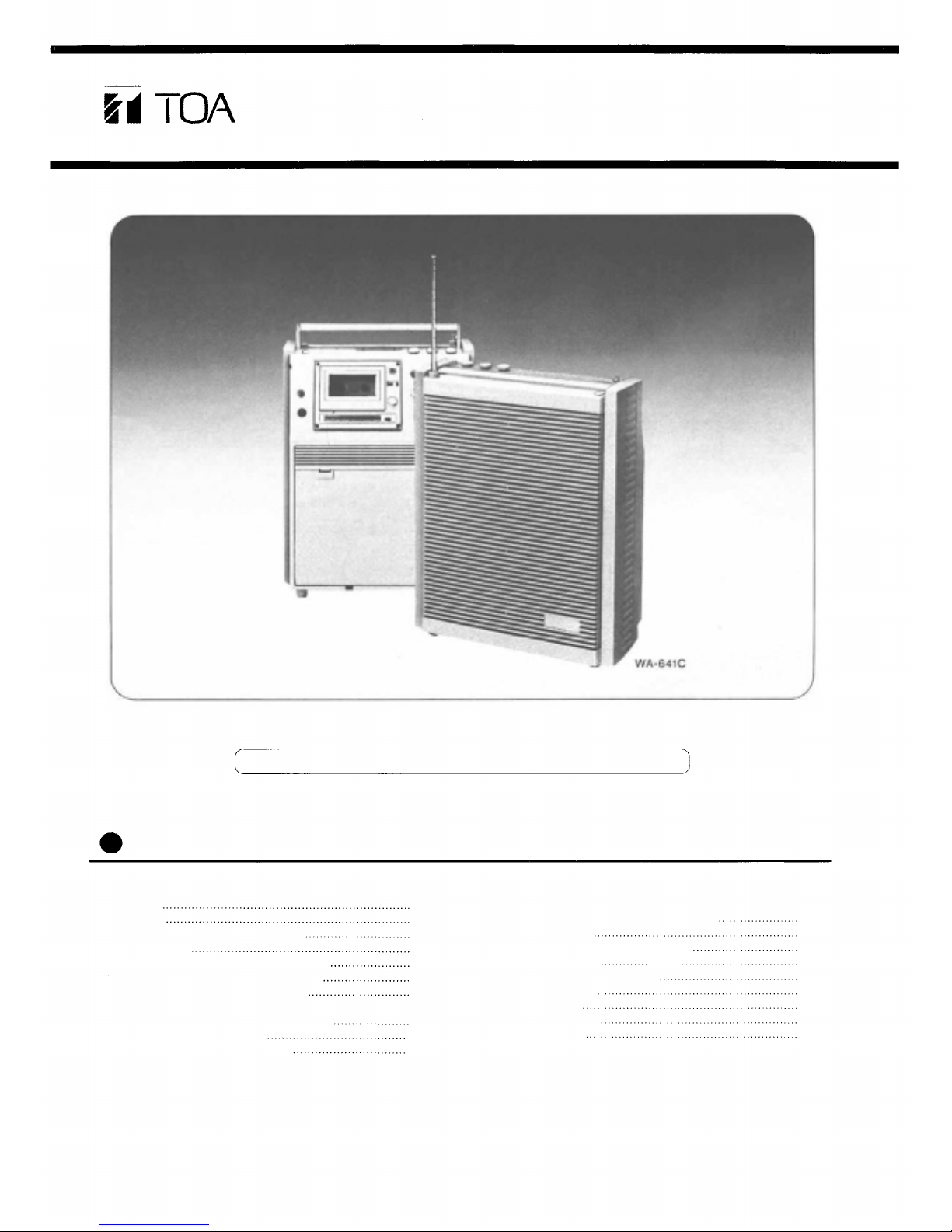
Operating Instruction Manual
MEETING AMPLIFIER
WA-641
WA-641C
For wireless applications, use the WTU-770 tuner module.
Contents
Features
Important
Each Part Names And Functions
Power Source
Mounting The Wireless Tuner Module
Operating The Wireless Microphone
Operating The Wired Microphone
Using External Equipment
Operating The External Speaker
Using The Aux Input
Using The Line Out Jack
1
1
2
4
5
6
7
7
8
8
Using The Cassette Deck
Each Part Name And Function
Playback
Fast Forward And Rewind
Recording
Tape Travel Modes
Cassette Tapes
Maintenance
Troubleshooting
Specifications
TOA Corporation
9
10
10
11
12
13
13
14
15
Page 2
Features
A maximum of two wireless microphones can be
used by mounting the optional wireless tuner
module in unit.
Powerful sound thanks to a 20cm 2-way speaker.
Rated power output of 15 watts and maximum
power output of 20 watts.
Three-power-source operation; AC mains, R20P
dry cells (8 pieces) and external power supply.
Compartment wide enough to store a wired microphone (with 5-meter cable) and two wireless
microphones.
Important
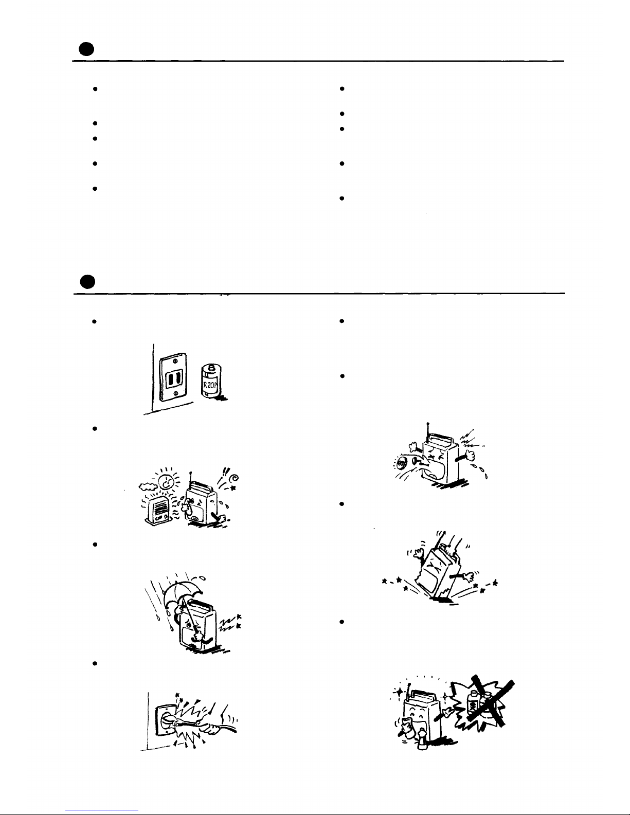
Power source should be AC mains, R20P dry
cells (8 pieces) or external power supply (12V
DC).
Do not install unit in a car parking under the
scorching summer sun or in locations where unit
is exposed directly to the sunlight. Also avoid in-
stalling unit close to heaters.
Tone control that always provides clear speech
or music.
AUX input control.
It is possible to use the wired microphone jack
and AUX jack for both balanced and unbalanced
type plugs.
A digitally controlled auto-reverse cassette deck
enables long, continuous play without turning the
tape. (WA-641C only.)
The cassette deck employs a recording circuit
with AGC function for easy recording of the
broadcast. (WA-641C only.)
When unit is unused, turn off power switch and
remove the power cable from an AC outlet. Only
setting the power switch to OFF keeps unit consuming power of about 4 watts.
If hairpins, coins, etc. enter unit, this can involve
dangers of electric shocks or breakdowns. When
metallic stuff enters unit, be sure to set the power switch to OFF immediately, remove power
cable and contact your nearest Toa dealer.
Take care that unit is not exposed to rain or that
raindrops should not enter unit as it will cause
electric shocks and breakdowns of unit.
Be sure to take hold of a plug to unplug the
power cable from an AC outlet, otherwise the
cable is disconnected.
When carrying unit from one place to another, do
not give strong shocks to unit nor handle it
roughly.
Use a dry cloth to wipe down the exterior of the
case. When the case is extremely dirty, clean
with a soft cloth slightly damped in a neutral
cleanser. Never use benzine or thinner as its use
can deform or discolour the case.
- 1 -
Page 3
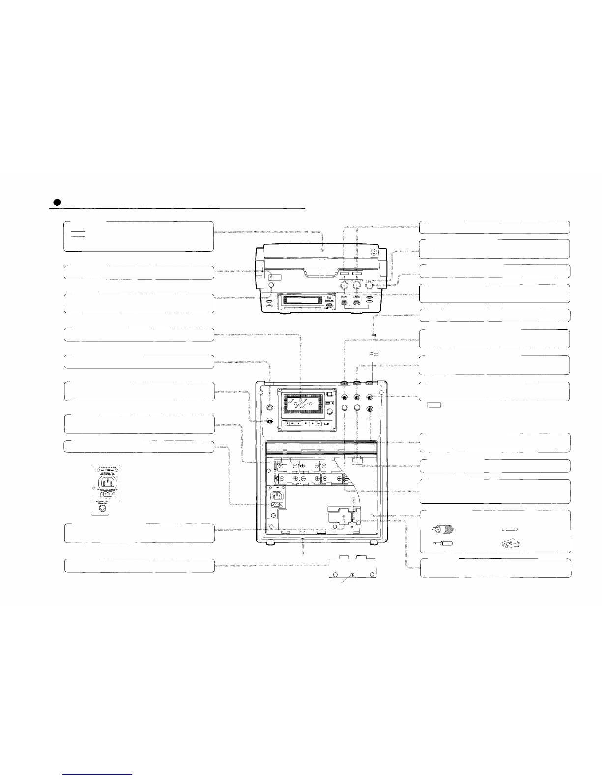
Each Part Names And Functions
Carrying handle
Use this handle to carry unit from one place to another.
Note
This handle is only designed for carrying unit. Never use t he
handle for the purposes of permanent suspension of unit.
Power indicator
When the power switc h is set to ON, this lamp comes on.
Power switch
Press this switch to sw itch power on. To switch power off, press
the switch again.
Cassette deck (W A-641C)
Refer to page 9 for operation.
Line o ut jack (600 ohms, 0 dBV)
Use this jack when recording or connecting the external amplifier.
External speaker connector
This connector connects to the external speaker using an
attached plug.
Dry cell case
Eight of R20P (Size "D" ) is loaded. Observe polarities when loading dry cells.
External DC power input terminal
(220V/240V AC version)
* Set the voltage selector swi tch
to 240V when unit is operated
on 240V A C.
Wireless tuner module receptacle
A maximum of 2 wirel ess tuner modules (optional) can be
mounted in th is r eceptacle.
Tuner cover
Be sure to fix this cover in place after mounting the tuner module.
(WA-641C)
Notch fo r power cable passage
Tuner cover fixing screw
Frequency marker
Attach the frequency markers supplied with the tuner module.
Radio signal reception indicator
This lamp comes on when unit receives a signal f rom the wireless
microphone.
Wired microphone volume control.
Mic 1/Mic 2 volume control
This is a volume control f or both the wireless and wired microphones.
Aerial
Fully extend this aerial when using the wireless microphone.
Mic 1 (wired mic) jack (600 ohms, -54dBV)
This jack can be used for both balanced and unbalanced type
plugs.
Mic 2 (wired mic) jack (600 ohms, -54dBV)
This jack can be used for both balanced and unbalanced ty pe
plugs.
Wired microphone jack (600 ohms, -54dBV)
This jack only connects to the wired microphone, and can be
used fo r both balanced and unbalanced plugs.
Note
No wireless microphone can be used when wired microphones
are plugged into Mic 1 and Mic 2 jacks. The volume control cor-
responding to each microphone is located immediately over the
jack.
AUX input jac k (500kohms, -20dBV)
This jack can be used for both balanced and unbalanced typ e
plugs.
AUX input volume control
Bass/treble control
Rotation of this knob in the counterclockwise direction reduces
the bass response and turning it clockwise reduces the high fre-
quency response.
Compartment cover
Accessories are provided on the reverse side of this cover.
External speaker
plug x 1,
Single pole x 1,
Fuse x 1,
External DC plug x 1
Compartment
Power cables, wi red microphone, wireless microphones, etc. are
stored in this compartment.
- 2 - - 3 -
Page 4
Power Source
AC MAINS OPERATION
Plug the supplied power cable in an AC inlet, and
then plug it in an AC outlet,
Note
Unplug unit when not in use.
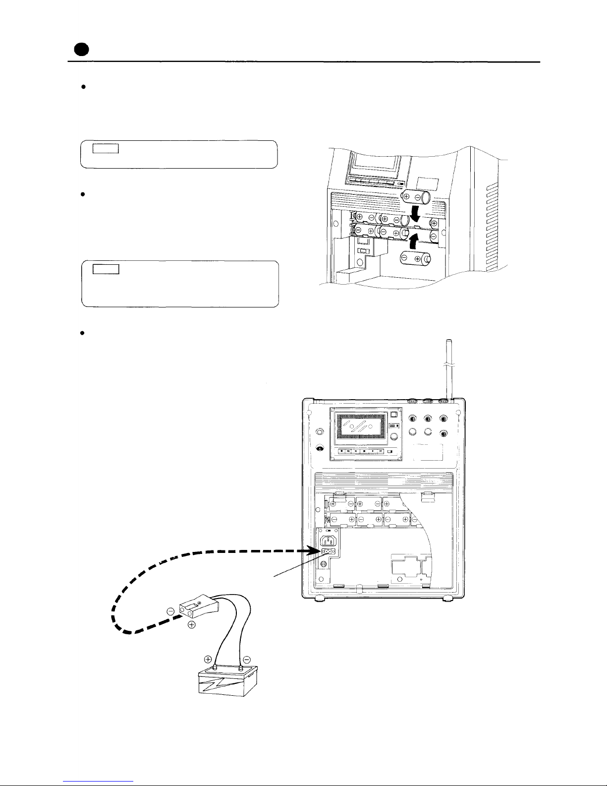
DRY CELL OPERATION
Use eight of R20P dry cells. Observe polarities
when loading them into the dry cell case. Removal of the power cable from an AC outlet after
loading the dry cell automatically switches over
the power source to the dry cell power supply.
Note
If unit is not in use for two weeks or longer,
take the dry cells out of unit to prevent
breakdowns the dry cell leakage causes.
OPERATION ON EXTERNAL 12V DC (OPERATIONAL ON 10V to 16V DC)
A storage battery may be used by means of a
plug for external power supply (standard accessory). In making its connection, observe correct
polarity.
INPUT TERMINAL FOR EXTERNAL
DC POWER SOURCE
(WA-641C)
Storage battery (12V DC)
- 4 -
Page 5
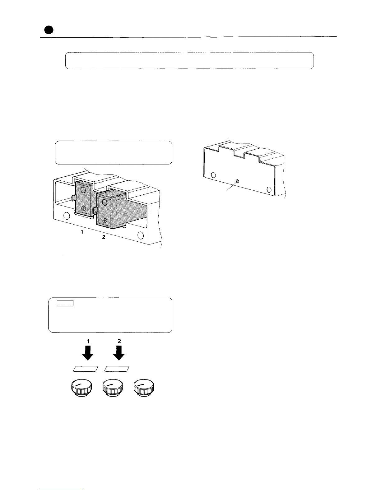
Mounting The Wireless Tuner Module
For tuner module, use the TOA model WTU-770
1. Remove the compartment cover.
2. Remove the tuner cover of the tuner receptacle.
3. Insert the tuner module into the lengthwise receptacle as shown in Fig. 1, taking care so that
the module's top and bottom sides may not be
reversed. (See Fig. 1.)
Both the left and the right hand side receptacles correspond to Mic 1 and Mic 2, respectively.
Fig. 1. The WTU-770 module inserted into the receptacle
lengthwise.
4. Attach the frequency marker supplied with the
module to the corresponding volume control.
(See
Fig.
2.)
5. Fit the tuner cover in place after mounting the
tuner module. (See Fig. 3.)
* Be sure to fit the tuner cover in place to prevent
electric shocks or breakdowns of unit, caused
when metallic stuff enters unit.
Fixing screw
Fig. 3. Fitting the tuner cover
Note
Special cares are required so as not to insert
the tuner module into the wrong receptacle
nor attach the frequency marker to the wrong
volume control.
Fig. 2. Volume control on top panel
- 5 -
Page 6

Operating The Wireless Microphone
Use the wireless microphone of which frequency is the same as that
of the tuner.
Extend an aerial to its full length.
1.
Place the power switch in the ON position.
2.
Set the power switch of the wireless microphone
3.
to ON.
*The radio signal reception indicator comes on.
Adjust the volume control for the desired volume.
4.
Adjust the Bass/Treble control for the desired
5.
tone.
(WA-641C)
Notes
1. The Mic 1 and Mic 2 volume controls are for
both the wireless and wired microphones. Con-
nection of the wired microphone to the mic-
rophone input jack makes it impossible to use
the wireless microphone on that input.
2. Take care about disturbing radio waves. When
the meeting amplifier is installed very close to
equipment that produce electric noise such as
industrial-use sewing machines and fluorescent
lamps, sound transmission from the wireless microphone can be interrupted. In such a case, put
the wireless microphone closer to the amplifier or
change the location of the amplifier.
3. Take care about a "null" spot. Signal dropouts
(momentary losses of reception) are caused by
interference and/or reflection of the transmitted
radio waves, a condition that constantly changes
as the wireless microphone is moved indoors.
The place producing the signal dropouts is called a "null" or "dead" spot. To solve this problem, position the amplifier further away from steel
desks or lockers or move it one to two meters.
- 6 -
Page 7

Operating The Wired Microphone
Set the power switch to ON.
1.
Connect the wired microphone to the desired in-
2.
put jack out of Mic 1, Mic 2 and wired mic jacks.
* The input sensitivity is 600 ohms and -54dBV.
Both of the balanced and unbalanced type
microphones can be connected to any of these
jacks.
Adjust the volume control for the desired volume.
3.
* The volume control corresponding to each mic-
rophone is located immediately over the jack.
Adjust the bass/treble control for the desired
4.
tone.
(WA-641C)
Using External Equipment
OPERATING THE EXTERNAL SPEAKER
External speaker
connection plug
EXT.
SP.
EXT. SP.
External speaker connector
1. Connect an attached external speaker connection plug to the speaker cable.
Note
Use the speaker with rated power input of 20
watts or more and impedance of 8 to 16
ohms.
2. Insert the plug into the external speaker connector.
This plug connection disconnects the speaker
circuit in the meeting amplifier and only oper-
ates the external speaker.
External speaker (20W, 8-16 ohms)
This plug connection operates both the built-in
speaker and external speaker at a time.
(WA-641C)
- 7 -
Page 8

USING THE AUX INPUT
AUX input jack
AUX input volume control
Bass/treble control
(WA-641C)
Phone plug
The AUX input jack is used for connection of a record player or cassette deck. Adjust the AUX input
volume control for the desired volume. Tone control
can be performed with the bass/treble control. The
input sensitivity is 500k and -20dBV. For connection, use a phone plug supplied. The balanced type
plug may also be used.
Record player (Ceramic cartridge type)
USING THE LINE OUT JACK
LINE OUT jack
Phone plug
The LINE OUT jack connects to an extension ampli-
fier or cassette deck used for recording. For con-
nection of these equipment, use a phone plug supplied. The output sensitivity is 60011 and 0 dBV.
To AUX input
(WA-641C)
Extension amplifier
- 8 -
Page 9

Using The Cassette deck WA-641C
EACH PART NAME AND FUNCTION
Recording button/recording mode indicator
Pressing this button causes a built-in red
LED to come on and puts unit in the record-
ing mode. Recording can be started when
the direction selector button is pressed. For
details, refer to page 11.
Dust cover (cassette holder)
Eject button
Pressing this button opens the dust cover
and allows the tape to be loaded or re-
moved. Do not press this button during tape
run as this can damage the tape. When you
want to remove the tape, be sure to press
the Stop button to s top tape moti on b efore
pressing this button.
Tape counter/Counter reset
button
Press this button to reset the
tape counter display to
"000".
Fast forward/Rewind but-
tons
Press this button to send the
tape forward or in the re-
verse direction at top speed.
Stop button
By pressing this button tape
motion can be stopped.
Direction selector/indicator
This selector allows the tape to travel in the
forward or reverse direction
playback or recording. When pressed, the indicator lights green to indicate the tape travel
direction.
- 9 -
for
Tape (playback level) control
Use this control to adjust the
output signal level during
playback.
Travel mode selector
This selector is used to
change over tape travel
modes
details, refer to page 12.
For
Page 10

PLAYBACK
1.
Switch power on with the tape control rotated fully counterclockwise.
After opening the dust cover by pressing the
2.
Eject button
exposed tape face down.
Select the desired tape travel mode with the
3.
Travel mode selector. (For the tape travel mode,
refer to page 12.)
load the cassette tape with the
FAST FORWARD AND REWIND
4.
Press the preferred Direction selector
and the tape starts to travel and at the same
time, the Direction indicator comes on to indicate
the tape travel direction.
Adjust the Tape control for desired playback
5.
level, turning the control clockwise.
To stop playback, press the Stop button
6.
Press the preferred Fast forward button
1.
or
or
- 10 -
To stop the fast forward operation, press the
2.
Stop button
Even when the tape is not travelling, pressing
the Fast forward button sends the tape running
at top speed.
If the Fast forward button is pressed during re-
cording, the recording is stopped and the tape
is put in the fast forward mode.
The tape travel is automatically stopped when
the tape is fully rewound on the reel.
Tape motion stops.
Page 11

RECORDING
Recording can be easily achieved without setting a recording level
with an AGC (Automatic Gain Control) being employed in the re-
cording circuit.
Switch power on.
1.
Open the dust cover by pressing the Eject but-
2.
ton
posed tape face down.
Select the desired tape travel mode with the
3.
Travel mode selector. (For the tape travel mode,
refer to next page.)
and load the cassette tape with the ex-
Press the Recording button
4.
mode indicator comes on and at the same time,
the two direction indicators both blink.
Lights
Blink
The recording
Notes
When you use the tape of which erasure prevention tabs have been removed, the Record-
ing mode indicator or the Direction indicator
can fail to come on.
If one tab has been removed.
Recording mode indicator... Lights.
Direction indicator... Only either or the two
blinks.
If two tabs have both been removed.
Recording mode indicator... Does not light.
Direction indicator... Neither indicator
blinks.
Recording is only possible in the direction
indicated by the blinking direction indicator
if only either of the two indicators is blinking.
Press the preferred Direction button, and that
5.
pressed Direction indicator changes indication
from blinking to lighting (the other Direction in-
dicator goes out). At this point, you can begin
recording. (If you reset the tape counter display
to "000" or make a note of the number on the
counter before recording, you can come back
easily to the point from which recording got
started after it is finished.)
When you wish to temporarily stop recording,
6
.
press the Stop button.
Note
When in the recording mode, all input signals
are recorded being mixed.
Page 12

If you want to repeat recordings in the
same tape travel direction as that used in
the preceding recording.
Pressing the Recording button
cording puts unit in the standby mode. In this
event, the Recording mode indicator remains lit,
with the Direction indicator in use switched from
lighting to blinking.
Tape travel direction
Remains lit
during re-
Blinks
TAPE TRAVEL MODES
There are three tape travel modes.
2. To restart recording, press the Direction indicator (button) that is blinking. The indicator
changes indication from blinking to lighting,
allowing you to begin recording.
By repeating the above steps 1 and 2 different
programme sources can be recorded one after
another in the same tape travel direction.
When you wish to reverse the tape travel dur-
ing recording mode in the
direction, de-
press the recording button to place the deck
on standby and then depress the
travel
button. It is impossible to reverse the tape
motion from
during recording (for
to
protection of a recording mode in the
track).
Set the Travel mode selector to required position.
1.
2.
3.
Playback
Mode
One-way recording or playback.
Two-way recording or playback.
Continuous repeat playback. The selection
of this mode during recording results in
two-way recording.
Travel
button
Tape run
Tape run
Tape run
Stops at tape end.
Actions
Stops at tape end.
Stops at tape end.
Automatically reversed
at tape end.
Tape run
Travel mode selector
The table below shows actions resulting from operation of both the Travel button and Travel mode
selector.
Recording
Mode
Travel
button
Tape run
Tape run
or
Tape run
Stop at tape end.
Actions
Stops at tape end.
Stop at tape end.
Automatically reversed
Tape run
at tape end.
Tape run
Tape run
Automatically reversed
Tape run
Automatically reversed
at tape end.
at tape end.
Stops at tape end.
Automatically reversed
Automatically reversed
at tape
Tape run
at tape
Tape run
end.
end.
- 12 -
or
Tape run
Stops at tape end.
Page 13

Cassette Tapes
Our deck is designed for use with the normal
tape only. Do not use chrome tapes or metal
tapes. If you use other tapes than the normal
tape, the sound quality will deteriorate or pre-
ceding recording cannot be completely erased
when recorded again.
Sounds can be harsh when playing back a tape
recording with the Dolby or similar noise reduction process. Use tapes recorded without the
noise reduction process.
Since the base of the C-120 tapes is thin and
easily damaged, they are not recommended for
use with our deck. Use the C-46, C-60 or C-90
tapes.
Before using a tape, check to confirm if tape
slack exists. As tape slack causes the tape twist
or tangle around the pinch wheel and capstan,
take up slap, if necessary, by inserting a pencil
through the reel hub and turning it as indicated
in the figure below.
Do not store tapes in a hot moist place or close
to a television or speaker. To prevent deterioration of tape quality, loss of recording, and noise
generation, always store tapes in a cool, dry
place.
Cassette tapes are provided with erasure pre-
vention tabs to avoid the accidental erasure of a
recording. If you want to keep the recording, re-
move the tabs with a screwdriver.
Tab for side A
To re-record, cover the tab opening with a double layer of adhesive tape.
Tab for side B
Adhesive tape
Maintenance
CLEANING THE HEAD SECTION
The head section is composed of the heads, cap-
stans and pinch rollers, and with extended use
these parts accumulate dust, dirt and grease easily
as the tape runs. If this assembly gets dirty, this
downgrades the sound quality and also leads to unstable operation. To prevent this, clean the head
section regularly with a cleaning tape commercially
sold in the market or cleaning swabs slightly
damped in alcohol.
CAUTION
Never use a screwdriver or metallic bar.
When cleaning with the swab, switch power off and
remove the dust cover (cassette holder) by lifting it
up.
Pinch roller
Recording/playback head
Capstan
Pinch roller
Erasing head
DEMAGNATIZING THE HEAD
The recording head becomes magnetized when
you use the tape deck for prolonged periods of
time. This results in noise being generated and loss
or recording which you want to keep. The recording
head should therefore be demagnetized regularly
with the head eraser commercially sold in the market.
CAUTION
Do not put any metallic stuff other than the
eraser or magnets closer to the head.
Do not grease any section as this causes
breakdown of the deck.
- 13 -
Page 14

Troubleshooting
Symptom
Even when power switch is set to ON,
power indicator does not come on.
(No power is supplied.)
No output sound.
If
wireless
The radio signal reception does
not come on.
mic is
(Radio signal is not received.).
used.
No output sound.
No playback sound.
If
Recording button defies
casette
attempts to depress it.
Confirmation
[AC Mains operation]
Is power cable plug inserted
into wall AC outlet?
[Dry cell operation]
Is polarity proper?
Volume control is placed in
minimum position?
Is aerial fully extended?
Is tuner module mounted?
Is wireless mic power switch set
to ON?
Has wireless mic dry cell not
been exhausted?
Is wired mic not connected?
Is playback level control set to
minimum?
Have erasure prevention tabs
been removed?
Remedy
Plug power cable into AC outlet.
Re-load dry cells in proper
polarity. (See page 4.)
Turn control clockwise.
Fully extended aerial.
Mount tuner module.
Place mic power switch in ON
position.
Change dry cell with new one.
Remove wired mic.
Rotate control clockwise?
Cover tab openings with
adhesive tape.
tape
Playback sound is distorted.
is
Recording cannot be erased
used.
completely.
High frequencies are weak.
Unstable tape travel.
Fast forward/rewind speed is
slow.
Is head section not dirty?
Has tape not been worn out?
Is there not tape slack?
Clean head section.
Use other tape for playback. If
that tape produces no problem,
replace original tape with new
one.
Take up tape slack using
pencil.
- 14 -
Page 15

Specifications
Model
Power Requirement
Rated Output
Power
Consumption
Frequency Response
Total Harmonic Distortion
Inputs
Outputs
Signal to Noise Ratio
Tuner Section (WTU-770)
Aerial system
Receiving Sensitivity
Squelch Sensitivity
Receiving System
Signal to Noise Ratio
Cassette Section
Track Format
Recording System
Tape Speed
Wow & Flutter
FF/REW Time
Ambient Temperature
Dimensions (W×H×D)
Weight
Finish
* Specifications are subject to change without notice
AC
DC
Wired Mic
Auxiliary
External
Speaker
Line out
Mic 1, 2:—54dBv 600 ohms (Swtichable with wireless microphone)
More than 80dB (20dBµV input, 1kHz Mod. 40kHz Dev.)
More than 75dB (20dBµV input, 1kHz Mod. 15kHz Dev.)
More than 95dB (102dB: Aweight) (60dBµV input, 40kHz Dev.)
More than 90dB (102dB: Aweight) (60dBµV input, 15kHz Dev.)
WA-641
220V/240V AC (Selectable), 50 Hz
Dry Cells-8pcs. (R20P or D size), External DC 10 to 16V
15W at AC
70 to 10k Hz 3dB deviation
Less than 3% (at rated output)
8 to 16 ohms, more than 20W of rated input
More than 70dB (at rated output)
-10 to 40 °C (14 to 104 °F) at AC
0 to 40 °C (32 to 104 °F) at DC
366×456×200 mm (14.4" × 18.0" × 7.9")
7.3 kg
(16.1 Ibs)
(Max 20W),
44W (Rated output)
1300mA
-20dBV 500k ohms
0dBV 600 ohms
Rod aerial
14dBuV (0dB = 1µ V)
Superheterodyne System
Light green (ABS resin)
6W at DC
2 track-1 channel (Mono)
Within 100 sec. (C60 tape)
WA-641C
AC bias
4.8cm/sec.
0.3% WRMS
8.3 kg (18.3 Ibs)
Accessories
Dust cover
Single pole plug
Plug for connection to external power supply
Plug for connection to external speaker
Fuse (T500mA)
Operating instruction manual
1
1
1
1
1
1
TOA Corporation
PRINTED IN JAPAN
133-07-082-40
 Loading...