

Page 1
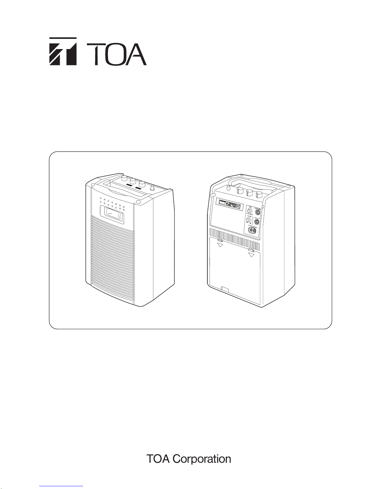
WIRELESS MEETING AMPLIFIER
Thank you for purchasing TOA’s WA-1830M-AS and WA-1830MB-AS Wireless Meeting Amplier.
Please carefully follow the instructions in this manual to ensure long, trouble-free use of your equipment.
WA-1830M-AS
WA-1830MB-AS
INSTRUCTION MANUAL
Page 2

1. SAFETY PRECAUTIONS
............................................................................................................ 3
2. GENERAL DESCRIPTION
.......................................................................................................... 4
3. FEATURES
....................................................................................................................................... 4
4. HINTS FOR BETTER USE
.......................................................................................................... 5
5. NOMENCLATURE AND FUNCTIONS
..................................................................................... 5
6. ABOUT THE OPERATING MP3
................................................................................................. 9
7. ABOUT THE POWER SOURCE
................................................................................................ 10
7.1. Using AC Power Supply ................................................................................................................. 10
7.2. Using Battery .................................................................................................................................. 11
7.2.1. Battery Type ......................................................................................................................... 11
7.2.2. Battery Installation (Remove) .............................................................................................. 11
7.2.3. Install New Battery (WA-1830M-AS only) ............................................................................ 11
7.2.4. Power Supply Switching ...................................................................................................... 11
7.2.5. Guide Lines on Battery Recharge Times ............................................................................. 11
8. USING A WIRED MICROPHONE
.............................................................................................. 12
9. USING A WIRELESS MICROPHONE
...................................................................................... 12
9.1. Tuner Unit Installation .................................................................................................................... 13
9.2. Frequency Setting .......................................................................................................................... 13
10. ABOUT EXTERNAL EQUIPMENT
........................................................................................... 13
10.1. When Using External Speakers ................................................................................................... 13
10.2. When Using an External CD Player ............................................................................................. 14
10.3. When Using an External Amplifier ............................................................................................... 15
11. TROUBLESHOO TING
................................................................................................................... 15
12. SPECIFICATIONS
.......................................................................................................................... 16
TABLE OF CONTENTS
2
Page 3

3
1. SAFETY PRECAUTIONS
• Be sure to read the instructions in this section carefully before use.
• Make sure to observe the instructions in this manual as the conventions of safety symbols and messages
regarded as very important precautions are included.
• We also recommend you keep this instruction manual handy for future reference.
WARNING
Indicates a potentially hazardous situation which, if mishandled, could
result in death or serious personal injury.
• Warning: To reduce the risk of re or electric shock, do not expose this apparatus to rain or moisture. Do not
place objects lled with liquids such as vases on the apparatus.
When Installing the Unit
• Use the unit only with the voltage specied on the unit. Using a voltage higher than that which is specied may
result in re or electric shock.
• Do not cut, kink, otherwise damage nor modify the power supply cord. In addition, avoid using the power cord
in close proximity to heaters, and never place heavy objects -- including the unit itself -- on the power cord, as
doing so may result in re or electric shock.
• Avoid installing or mounting the unit in unstable locations, such as on a rickety table or a slanted surface.
Doing so may result in the unit falling down and causing personal injury and/or property damage.
• To prevent lightning strikes, install the unit at least ve meters away from a lightning rod, and yet within the
protective range (angle of 45°) of the lightning conductor. Lightning strikes may cause a re, electric shock or
personal injury.
When the Unit is in Use
• Should the following irregularity be found during use, immediately switch off the power, disconnect the power
supply plug from the AC outlet and contact your nearest TOA dealer. Make no further attempt to operate the
unit in this condition as this may cause re or electric shock.
· If you detect smoke or a strange smell coming from the unit.
· If water or any metallic object gets into the unit
· If the unit falls, or the unit case breaks
· If the power supply cord is damaged (exposure of the core, disconnection, etc.)
• Do not insert nor drop metallic objects or ammable materials in the ventilation slots of the unit’s cover, or the
MP3 player, as this may result in re or electric shock.
• Do not touch a plug during thunder and lightning, as this may result in electric shock.
• To prevent a re or electric shock, never open nor remove the unit case as there are high voltage components
inside the unit. In addition, modifying the internal parts or circuit may cause the unit to be against the
regulations in your country.
Refer all servicing to your nearest TOA dealer.
CAUTION
Indicates a potentially hazardous situation which, if mishandled, could
result in moderate or minor personal injury, and/or property damage.
When Installing the Unit
• Never plug in nor remove the power supply plug with wet hands, as doing so may cause electric shock.
• When unplugging the power supply cord, be sure to grasp the power supply plug; never pull on the cord itself.
Operating the unit with a damaged power supply cord may cause a re or electric shock.
Page 4

4
• When moving the unit, be sure to remove its power supply cord from the wall outlet. Moving the unit with the
power cord connected to the outlet may cause damage to the power cord, resulting in re or electric shock.
When removing the power cord, be sure to hold its plug to pull.
• Avoid installing the unit in humid or dusty locations, in locations exposed to the direct sunlight, near the heat-
ers, or in locations generating sooty smoke or steam as doing otherwise may result in re or electric shock.
• The socket-outlet shall be installed near the equipment and the plug (disconnecting device) shall be easily
accessible.
When the Unit is in Use
• Do not place heavy objects on the unit as this may cause it to fall or break which may result in personal injury
and/or property damage. In addition, the object itself may fall off and cause injury and/or damage.
• Do not stand or sit on, nor hang down from the unit as this may cause it to fall down or drop, resulting in per-
sonal injury and/or property damage.
• When the unit is not in use for 10 days or more, or when the AC power is used for operating the unit, be sure
to take the battery out of the unit because battery leakage may cause a re, personal injury, or contamination
of environment.
• Switch off the power, and unplug the power supply plug from the AC outlet for safety purposes when cleaning
or leaving the unit unused for 10 days or more. Doing otherwise may cause a re or electric shock.
· Do not short, disassemble, heat nor put the battery into a re.
· Do not solder a battery directly.
· Be sure to use the specied type of battery.
· Note correct polarity (positive and negative orientation) when inserting a battery in the unit.
· Avoid locations exposed to the direct sunlight, high temperature and high humidity when storing battery.
2. GENERAL DESCRIPTION
TOA’s WA-1830M-AS and WA-1830MB-AS are portable meeting ampliers featuring 2-way speaker system.
WA-1830M-AS has a MP3 player unit and WA-1830MB-AS has a MP3 player unit and Lead Acid battery.
Both models can accommodate 2 diversity wireless tuner units of crystal-controlled PLL synthesizer system
WTU-4800s. Other feature includes the anti-bacteria treated carrying handle.
3. FEATURES
• Excellent Sound Quality
Both the built-in cone speaker and constant directivity speaker feature the highest sound quality.
• High Intelligibility
New circuitry has been designed to reduce sound distortion at high-volume sound outputs to realize excellent
intelligibility for both quiet and loud sounds.
• High Power and Long Battery Life
Although rated at a high power output of 30 W, the WA-1830M-AS and WA-1830MB-AS consumes low power
to maintain a longer battery life.
• Lightweight Design
Carefully reviewed design and construction realize reduced and balanced weight that facilitates transport and
makes the Meeting Amplier seem lighter than it actually is.
• Improved Operating Ease
· Knobs are easy to operate, and indications are larger and more legible.
· Increased component storage volume is large enough to accommodate 2 wireless microphones, 1 wired
microphone and a dust cover.
· Design battery compartment to easy replacement battery with the new one.
· Snap-in type external speaker terminal facilitates external speaker connection.
Page 5

5
5. NOMENCLATURE AND FUNCTIONS
4. HINTS FOR BETTER USE
• Positioning Orientation
Position the unit with its front (speaker side) oriented toward the listeners to avoid feedback. If feedback
occurs, move the microphone away from the unit or decrease the output volume.
• Location
Sound from the speaker can be heard more clearly by positioning the unit above oor level, such as on a desk.
The distance between the meeting amplier and the wireless microphone can also be made longer.
• Dead Point
As the wireless microphone user moves, a point where signal reception is abruptly and temporarily lost may
be encountered due to radio signal reection or interference. To avoid such a dead point, keep the unit away
from walls or desks, or move the unit location approximately 1 – 2 m in any direction.
• Radio Signal Source Interference
Keep the unit away from uorescent lamps or computers, which can generate high frequency noise, as radio
interference could result, shortening the wireless microphone’s transmission distance.
• Wireless Microphone Distance
Keep the unit at least 3 m away from the wireless microphone. If the distance is shorter than 3 m, feedback
noise can be generated, resulting in radio interference.
• Cleaning
When cleaning, be sure to switch off the power, then wipe with a dry cloth. If the unit should become extremely
dirty over time, use a cloth dampened in a neutral detergent. Never use volatile liquids such as benzene or
thinner, because they can deform or discolor the unit’s case.
ON
OFF
MIC 1MIC 2WIRED MIC
010010 010
3
1
2
5
[Front]
5
2
6 7
[Rear]
8
12 12
14
10
9
11
13
15
17
18
19
20
16
POWER
LOW BATT.
RED
CHARGE BATT.
GREEN
[Tuner Cover]
1
2
21
To be mounted to the Wireless tuner receptacle (12)
4
[Top]
22
[Battery Unit] WA-1830M-AS does not include battery
To be installed in the battery compartment (9)
OPEN
WIRELESS MEETING AMPLIFIER
MIC 2 MIC 1
POWER
Page 6

1. Power switch
Turns the power ON and OFF when pressed.
2. Power Indicator
Lights green when the power switch is set to
the ON position, and ashes when the batteries
begin to lose their charge during battery-powered
operation.
3. Handle
Raise and use this handle to carry the unit.
Note: Use this handle only to transport the unit.
Never suspend the unit from this handle.
4. Low Battery Indicator / Charge Battery
The indicator light turns red when the battery
is low and the indicator light turns green when
battery under charging. No light indicates when
battery full charge.
5. Wireless Indicator LED
The light is orange when the unit receives the
radio signal from the wireless microphone.
6. Wireless Microphone Volume Control
As a general guide line. Set this control to posi-
tion 3 for clip-on wireless microphone and posi-
tion 7 of hand-held wireless microphone. These
position are marked with larger dot marking.
7. Wired Microphone Volume Control
Adjust the volume of the microphone connected to
the microphone Input terminal. As a general rule of
thumb, set this control to position 5 (the larger dot).
8. MP3 Player Unit
Details of operation described are on p.9 of this
manual.
9. Battery Compartment
Holds the unit’s cartridge-type battery case.
10. Internal or External Speaker Switch Selection
: Enables internal speaker only.
: Enables external speaker only.
11. External Speaker Terminal
Connect an 4 – 16 Ω speaker rated for at least
30 W to this terminal. Note the correct polarities
when connecting.
6
12. Wireless T uner Receptacle
Has 2 (optional) wireless tuners can be installed.
13. AC inlet
Connect the supplied AC power cord to this inlet.
14. Tone Control
Rotate clockwise to accentuate high frequency
sounds, and counterclockwise to accentuate low
frequency sounds.
15. Wired Microphone Terminal
Connect a wired microphone here. (Applicable
microphone: 600 Ω, –45 dB*, unbalanced, 6.3
mm phone jack)
16. External input Volume Control
Adjusts the sound volume of connected external
equipment.
17. External Output Terminal
Connect an external Wireless Meeting Ampli-
er or amplier to this terminal. (1 kΩ, 0 dB*,
Unbalanced, 6.3 mm phone jack)
18. External input Terminal
Enables connection to a CD player or other sound
source. Pin jack x 2 (monaural) (10 kΩ, –20 dB*,
unbalanced type)
19. Compartment Cover
20. Component Compartment
Used to store such components as the power
cord, wired and wireless microphones, and dust
cover.
21. Tuner Cover
This cover must be attached after installing the
tuner.
22. Battery Unit (WA-1830M-AS does not include
battery)
Details of using batteries are described on p.11 of
this manual.
* 0 dB = 1 V
Page 7

1. POWER
When the unit is turned ON, pressing this button
for 3 seconds will turn off the unit. When the unit
is turned OFF, pressing this button will turn on the
unit. Display will play to the last mode.
2. MUTE
In MP3 mode, pressing this button will mute the
sound. Press again, sound will appear. Display
Text ‘’ U-00 ‘’ will appear and blinking.
3. MODE
When the unit is turned ON, pressing this button
will switch between the modes. Display text will
appear “AUX → FM → USB → SD”.
4. (REPEAT)
While playing, pressing this button will switch
between : “REPEAT ALL → REPEAT FOLDER →
REPEAT 1 → PLAY ALL”.
5. PLAY 1
While playing, pressing this button will play 1
track then stop. Display text appear “ -1- “, then
“ “, and display time blinking.
6. RAN.
In MP3 mode, pressing this button enter the ran-
dom mode of track. Display text appear “ RDM “,
press again text will disappear.
7. AUX REC
In Aux mode, pressing this button will record to
SD Card. If SD Card is not inserted to the slot, the
unit will record to the inserted USB. If pressing
this button while recording, the unit will stop
recording, and the track that was being recored
will be saved in the last space of the folder. LED
is turned ON when the Record begins and will
OFF when the record ends (on Panel MP3).
Display text appear “ REC “ and time. In FM mode,
pressing this button enter the station saving
mode. Then, press play to save the current
frequency as a station or press or folder on
the remote control to choose position for saved
frequency. Then press this button for 3 seconds
to actually save this frequency to this position.
Display text appear “ SAVE “.
8. REC PLAY
In MP3 mode, Pressing this button will enter
record folder and play the latest recording.
9. (PLAY/PAUSE)
In MP3 mode, pressing this button, PLAY will
switch to PAUSE. Pressing again PAUSE will
switch to PLAY. Display will appear, and time
indicator blinking. If the unit has been STOPPED,
it will switch to PLAY. In FM mode, pressing this
button will skip to the Channel Frequency has
been saved.
In FM mode, pressing this button for 3 seconds
will automatically search and save available
station in a maximum number of 30 station.
Display CH01, CH02, ...CH30.
10. (Skip +)
In MP3 mode, pressing this button will skip to
the next track, keeping pressing this button will
fast-forward ( function only remote ).
In FM mode, pressing this button will tune up-
wards in frequency with each segment of 50 kHz.
Pressing this button for 3 seconds will search
stations upwards in frequency and the search will
automatically stop at the frequency where there
is station available.
7
F F
MUTE POWER
MODEPLAY1 RAN.
REC PLAY
STOPDEL
F
F
123
456
789
0
12
LR03, 1.5Vx2
UM-4 (AAA)
OPEN
14
11
7
4
3
2
17
24
25
1
6
5
8
9
13
15
16
18
10
26
SD/SDHC
DEL
PSET
AUX
REC
/AUTO
DIGITAL PLAYER/FM & RECORDER
IR
MODE
REC
88:88
AUXFMSDUSB
RDMBT
FOLDER ALLREPEAT1
[Remote control] [MP3 Player]
7
22
21
9
18
1
20
19
23
10
3
14
11
17
Page 8

11. (Skip -)
In MP3 mode, pressing this button will skip to
the last track, keeping pressing this button will
fast-rewind ( function only remote ).
In FM mode, pressing this button will tune
downwards in frequency with each segment of 50
kHz.
Pressing this button for 3 seconds will search
stations downwards in frequency and the search
will automatically stop at the frequency where
there is station available.
12. F (Folder +)
In MP3 mode, pressing this button enters the
next folder. In FM mode, pressing this button en-
ters the next saved station.
13. F (Folder -)
In MP3 mode, pressing this button enters the last
folder. In FM mode, pressing this button enters
the last saved station.
14. DEL
In MP3 mode, press this button to choose the
track that the user wants to delete and then press
it for 3 seconds to actually delete the track. Text
appear “ dEL “
15. STOP
In PLAY/PAUSE mode and if press this button,
the unit will STOP. Press STOP once will stop at
the currently played track. Press STOP twice will
stop at the rst track.
16. 0-9
Number buttons, 0-9 for MP3 mode. Track
number blinking. Quantity number track until
9999. In FM mode, pressing this button will
arouse (call out) saved station. Pushing this
button for 3 seconds will save the station
frequency radio.
17. (Decrease)
Keep pressing this button will decrease the
Volume ( Display U32 → U00 ).
18. (Increase)
Keep pressing this button will increase the Volume
( Display U00 → U32 ).
19. SD Card Input
For input SD card.
20. USB Card Input
For input USB.
Note : - Not recommended for charging.
21. Display Indicators
Indicator 188:88: This indicator illuminates by
counting / increasing when operating the MP3
player.
. For volume displayed (U-00 → U-32) with +/- 1.
. For FM Radio in increase - decrease vol mode
is displayed (87.50 → 108.00) with +/- 50 kHz.
. For FM Radio in play pause mode can be saved
and displayed (CH01 → CH30)
USB indicator: when connected this indicator
lights up with blinking on the display, le is ready
to operate.
SD indicator: when connected this indicator
ashes with blinking on the display, le is ready
to operate.
FM indicator: When FM mode is selected or when
it is turned on this indicator lights up with blinking
on the display.
Play indicator: in MP3 mode is illuminated with
blinking on the display, indicating it is operating
PLAY.
Pause indicator: in MP3 mode is illuminated
with blinking on the display , indicating it is operat-
ing PAUSE.
AUX indicator: when AUX mode is selected
input from AUX, Wire Mic, Wireless Mic connects
to MP3.
REC indicator: when AUX mode is selected then
press PSET then start REC Record and display
illuminated with blinking and the result is saved to
USB or SD Card, if USB or SD Card is installed.
22. AUX REC Indication
Turns on when turning Record results.
23. IR Receiver
For signal receiver from remote control.
24. Remote Battery Case
Insert 2 LRO 1.5V or UM-4 (AAA size) batteries,
note correct polarity (positive and negative orien-
tation) when inserting a battery.
25. Remote Cover
This cover must be attached after installing the
batteries.
26. IR T ransmitter
8
Page 9

6. ABOUT THE OPERATING MP3
9
MP3 PlayerRemote IndicationOperating Mode
- Press button MODE
"AUX→FM→USB→SD".
Display mode AUX
1.
2.
Display mode FM
Display mode USB
3.
4.
Display mode SD
while USB & SD install
a. USB & SD
install
- Press button
" REPEAT ALL →
Display
2.
1.
Display REPEAT ALL
Display PLAY ALL
4.
3.
Display REPEAT 1
SD install
- Press button PLAY1.
- Will stop after a track is finish.
- Press button
again will play
REPEAT FOLDER
to next track.
REPEAT FOLDER →
( Operates on MODE "SD and
REPEAT 1 → PLAY ALL ".
USB" or MP3 Mode ).
- Press button PLAY1
again will
normal play.
USB install
Display STOP
3.
4.
Display normal play
1.
2.
Display PLAY1
Display next track
SD install
Display normal play
1.
2.
Display change track
Random
- Playing normal condition.
-
Press button RAN. (Operates on
a new track random
conditions)
- Press button RAN. again will
normal play.
- Playing normal condition.
- Press button
will pause.
Display blinking
2.
1.
Display normal play
USB install
- Press button
again will
normal play.
* MP3 Mode (USB or SD)
* MP3 Mode (USB or SD)
* MP3 Mode (USB or SD)
* FM Mode
Display normal play
1.
2.
Change next channel
FM Mode
- Playing normal condition.
-
Press button
will change
next channel.
MODE
MODE
PLAY 1
RAN.
/AUTO
after completion will play in CH01.
Display normal play
1.
2.
Search and save from
CH01
FM Mode
automatically search and save
- Press the button 3 seconds will
channel from CH01 until CH30
Page 10

10
first tack in it.
Record start at SD
is made Max).
Display AUX mode
this position.
to actually save this frequency to
- Press button AUX REC for 3 sec
saved frequency.
to choose channel position for
F or F on the remote control
frequency as a station or press
- Press PLAY to save the current
station saving mode.
- Press button AUX REC enter the
Display normal play
1.
2.
CH initial frequency
FM Mode
Display normal play
4.
3.
If Select no 9, frequency
FM Mode
CH09 same with CH02
* FM Mode
* MP3 Mode (USB or SD)
5.
Record start at SD
(for prepared recording).
4.
Time indication blinking
the last space of the folder.
6.
Display AUX mode
- Press button to hold, press
will stop, and will be saved in
3.
Display text appear " rEC " and time.
again will continue to Record.
1. 2.
Press AUX REC
AUX Mode and insert SD card
- Press button AUX REC again
USB card and volume control
- View second will be record
at SD as first priority and then
USB install
Display normal play
1.
2.
Play the first tack in it.
RECORD folder and play the
- Press this buttons will enter
* MP3 Mode (USB or SD)
- Press button MODE (display AUX)
WIRED MIC, WIRELESS MIC
(will save input from AUX IN,
and then press button AUX REC
Operating Mode IndicationRemote MP3 Player
Beginning play in CH01
4.
3.
Until CH30
PSET
REC PLAY
7. ABOUT THE POWER SOURCE
The WA-1830 Series Wireless Meeting Amplier is designed to operate on both home-use AC power and
specied rechargeable battery.
7.1. Using AC Power Supply
Remove the power cord from the component compartment, and connect to a standard AC outlet. Always be
sure the unit’s power is switched OFF before connecting or disconnecting the power cord from the AC outlet.
Notes :
• Approximately 1 W is continually consumed even if the power switch is set to the OFF position.
• When the unit is not used, detach the power cord from the AC outlet.
Page 11

11
D
a
n
g
er
of
e
xp
l
osi
o
n
i
f
b
atte
ry
is
in
R
eplac
e only
with the sa
RECH
A
R
G
EABLE BAT
TE
R
LEA
D
A
C
ID BATT
R
emov
e the battery
then pul
ling it out.
c
as
e by
lifting firs
t,
Battery Repla
c
ement
CAUTI
ON !
Faston-sleeve at inner
and top position
Color Black
Color Red
CAUTION !
Battery
Repl
acem
e
nt
c
as
e by
l
ifting first,
then pulling it out.
R
emov
e the batt
ery
LE
A
D
A
C
I
D BATT
R
E
C
HARGE
ABLE
B
ATTE
R
Replac
e only
w
ith the s
a
D
a
n
g
e
r
o
f
e
xp
l
o
sion
i
f
b
a
tte
ry i
s i
n
LINEOUT
AUX IN
WIRED
AUX IN [MONO]
1
TONE
2
LINEOUT
AUX IN
WIRED
AUX IN [MONO]
1
TONE
2
7.2. Using Battery
7.2.1. Battery Type
Lead Acid Battery 12 V, 2.3 Ah. Reference dimension:
178 (w) x 60 (h) x 34 (d) mm / (7” x 2.36” x 1.33”)
7.2.2. Battery Installation (Remove)
Step 1. Be sure to turn the power switch OFF and
detach the power cord from the AC outlet.
Step 2. Remove the compartment cover, attach the
ribbon upwards and then attach the battery
to the outside polarity. Connect the cables
according to the polarity of the red (+) and
black (–) battery.
Step 3. And then reinsert it in.
7.2.3. Install New Battery (WA-1830M-AS only)
2
Step
2
1
AUX IN
TONE
WIRED
LINE OUT
AUX IN [MONO]
Step 1. Be sure to turn off the power switch and detach the power cord front AC Outlet
Step 2. Remove the compartment cover, pull the ribbon ties to the unit, install battery type battery lead acid
12 V, 2.3 Ah, Red cable in battery (+) and black cable in battery (–).
Notes:
- Make sure the battery pin faston matches the specication (NT-5A).
- Make sure the battery is not damaged and the liquid does not Leak.
- When the rst usage is charging for approximately 10 hours.
- TOA’s can not supply for replacement battery.
Step 3. The longest ribbon is placed above the
battery and the short ribbon is on the bottom
side.
Step 4. The battery is directed to the unit, with the
slave / faston inside. push it in and click
(until it’s locked).
Step 5. Tie the ribbon tightly to make it safe from
shocks, using the buttery knot technique.
7.2.4. Power Supply Switching
Detaching the power cord from the AC outlet auto-
matically switches the power source from AC to the
battery.
7.2.5. Guide Lines on Battery Recharge Times
• A ashing (green) power indicator indicates that the battery are beginning to lose their charge and should be
connect AC inlet as early as possible.
• Intermittent sound output may occur even when the power indicator remains steadily lit. It is recommended
that the battery be replaced as early as possible in this case, too.
• Approximate battery usage times (replacement times) are shown below.
[When using the WA-1830 at room temperatures of 25°C]
Approximately 5 hours continuous with music playback. (Depend on the sound volume)
Note :
• Remove the battery when not in use for prolonged periods of time (10 days or more).
Page 12

12
8. USING A WIRED MICROPHONE
Step 1. Connect the wired microphone to the Wired
Microphone terminal.
Step 2. Set the power switch to the ON position.
Step 3. Set the Wired Microphone volume control to
approximately “5” on the dial.
Step 4. Adjust the sound quality using the tone
control.
9. USING A WIRELESS MICROPHONE
Step 1. Set the power switch to the ON position.
Step 2. Set the wireless microphone’s power switch
to the ON position. (The Radio Signal
Reception indicator lamp will light.)
Step 3. Adjust the volume by setting the correspond-
ing Wireless Microphone Volume control
(either WIRELESS MIC1 or WIRELESS
MIC2) to approximately “3” on the dial if a
Clip-on wireless microphone is used, or “7” if
a hand-held wireless microphone issued.
Step 4. Adjust the sound quality using the tone
control.
Notes :
• Use only TOA wireless microphones.
• Set the wireless microphone 1 and 2 to different channels from each, otherwise radio interferences.
• Keep the wireless microphone 3 – 20 m away from the Meeting Amplier.
• If the wireless microphone is positioned less than 3 m from the Meeting Amplier, feedback noise or radio
interference could result.
• When simultaneously using 2 different channels, keep the 2 wireless microphones at least 50 cm away from
each other.
• When the Meeting Amplier's power switch is set to the ON position, if the amplier's Radio Signal
Reception indicator lamp lights before the wireless microphone's power switch is turned ON, this indicates
that the currently set channel is in use. In such cases, change the different channel.
010
Power switch
Wired microphone
terminal
Tone control
Wired microphone volume control
LINE OUTAUX IN
LOW
AUX IN (MONO)
HIGH
WIRED MICTONE
010
Tone control
LINE OUTAUX IN
LOW
AUX IN (MONO)
HIGH
WIRED MICTONE
Wireless microphone
volume control
Power switch
OPENOPEN
OPENOPEN
010
Power switch
Wired microphone
terminal
Tone control
Wired microphone volume control
LINE OUTAUX IN
LOW
AUX IN (MONO)
HIGH
WIRED MICTONE
OPENOPEN
Page 13

13
9.1. Tuner Unit Installation
The following TOA tuner unit models can be used
WTU-4800s UHF Diversity Tuner Unit
Step 1. Set the power switch to the OFF position.
Step 2. Remove the Compartment cover.
Step 3. Remove the tuner cover located in the lower
left or right corner.
Step 4. Fully insert the tuner unit as shown in the
accompanying gure until it is securely
plugged into the back connector.
Note: Take care not to insert the tuner unit
up-side down.
Step 5. Install the tuner cover after mounting the
tuner unit.
Note: The tuner unit may become dislodged
if the tuner cover is not correctly
installed.
Step 6. Tuner unit frequency settings are explained in
the previous section Frequency Setting.
9.2. Frequency Setting
Set different channels as follows when adding a tuner unit or when radio interference occurs during use. Make
sure that the amplier's power switch is set to the OFF position when setting the channel.
Step 1. Select the channel number according to the enclosed frequency table.
Note: Be sure to select different channels when simultaneously using 2 wireless microphones.
Step 2. Using the setting screwdriver provided inside the manual book or the screwdriver supplied with the
expansion tuner unit, set the setting switch arrows to the desired channel numbers.
Note: Set the expanded tuner unit to a different channel number.
Step 3. Set the wireless microphone to the same channel number as that of the tuner unit.
Note: Using the setting screwdriver supplied with the wireless microphone, set the setting switch
arrows to the same channel number as that of the tuner unit. Details are explained in the wireless
microphone instruction manual.
WA-1830 M-AS
WA-1830MB-AS
INSTRUCTION MANUAL
10. ABOUT EXTERNAL EQUIPMENT
10.1. When Using External Speaker
[Recommended External Speaker and Stand]
Speaker : A rated input of 30 W or more, and impedance of 4 – 16 Ω.
Stand : Mount the speaker on the TOA ST-16, or other stand.
Notes :
• Note the correct polarities when connecting an external speaker.
• Take care that the External speaker terminals are not shorted during connection.
3
Step
4
Step
Page 14

14
10.2. When Using an External CD Player
Step 1. Connect the CD player or other sound source line output to the unit’s External Input terminal using a pin
cable. Input sensitivity is –20 dB, 10 kΩ. (0 dB = 1 V)
Step 2. Adjust the volume with the External Input Volume control.
Note :
The External Input terminal is monaural. Even if the input signal is in stereo, it is played back in single-channel
monaural.
010
LINE OUTAUX IN
LOW
AUX IN (MONO)
HIGH
WIRED MICTONE
External input volume control
External input terminal
Pin cable
2
1
Step
Step
CD player or other sound source
AM
FM
CHMEMOSTSLEEPALARM
+5
MHZ
KHZ
TR 18 72 : 29 ESP
CD
FM TUNER
OPENOPEN
Step 1. Connect the external speaker to the External speaker terminal.
Step 2. Using the Internal or External speaker switch selection.
• : Enables the internal speaker only.
• : Enables the external speaker only.
* External speaker
Recommended TOA speakers:
- BS-1030B
- BS-1030W
- SC-630
black wire
black
wire
white wire
white
wire
* ST-16
or
External speaker terminal
Internal or external speaker switch selection
1
2
Step
Step
Ω
Ω
External
speaker only
Internal speaker only
External speaker
30W minimum rated input,
Impedance 4 - 16 .
OPEN
External
speaker only
Internal speaker only
Page 15

15
10.3. When Using an External Amplifier
Step 1. Connect the unit’s External Line Output terminal to the external amplier’s AUX Input terminal or the
other units Line Input terminal using a phone plug cable. Output sensitivity is 0 dB, 1 kΩ. (0 dB = 1 V)
Symptom Cause Remedy
The power indicator lamp does not
light even when the power switch
is set to the ON position.
(Power is not supplied.)
[When operated on AC power]
The power plug is not connected
to an AC outlet.
Insert the power plug into the AC
outlet.
[When operated on battery]
Battery not inserted with
correct polarity.
Reinstall the battery correctly.
The low battery indicator does
light.
[When operated on battery]
Battery discharged. Charge battery.
No sound output. The Internal or External switch is
set to the External position.
Set the switch to the Internal
speaker position.
The volume control is set to the “0”
position
Rotate the volume control
clockwise.
When using a wireless microphone
The Radio signal reception
indicator lamp does not light.
(No signal reception.)
The tuner unit is not installed. Install the tuner unit.
The wireless microphone’s power
switch is switched OFF.
Set the wireless microphone power
switch to the ON position.
The wireless microphone’s
batteries have lost their charge.
Replace the microphone’s
batteries with new ones.
The wireless microphone’s
frequency setting (Channel)
does not match the tuner unit’s
setting (Channel).
Set both the wireless microphone
and the tuner unit to the same
frequency (Channel).
No sound output. The volume control is set to the “0”
position.
Rotate the Volume control knob
clockwise.
When using the MP3 Player
USB/SD CARD
Replace the format to MP3 or WAV.
USB / SD Card problem. Replace USB / SD Card of the
other / new.
No sound output.
The file can not be read. Format file is not supported.
Setting MP3 unit volume in volume
minimum position.
Push in MP3 from V 0 to V 1 ~
V 32 (as needed).
OPENOPEN
Pin cable
01 0
LINE OU
T
AUX IN
LO
W
AUX IN (MONO)
HIGH
WIRED MI
C
TONE
External output terminal
Phone plug cable
External amplifier, etc.
ref A-2000
OUTPUT RATED240W
model A-2240 H
MADE IN INDONESIA
TOA Corporation
360WMAX
CAUTION !
OUTPUT
Ω
ONOFF
PHANTOM
0 -30dB
220-240V~ 50/60Hz 238W
20A
21
31V
COMΩ4COM
24V
42Ω
100V
REC OUT AUX 2
1
2
AUX 1
3
MUTE ADJ
Ω
70V
CASE BEFORE DISCONNECT POWER SUPPLY.
DO NOT REMOVE TERMINAL OUTPUT COVER AND
INPUT
DO NOT USE THESE 4 , 70V AND
100V TERMINALS AT THE SAME TIME
-20dBV 10k Ω -20dBV 10k Ω
UNBALANCEDUNBALANCED
0dBV 600 Ω -60dBV 600 Ω
BALANCED
Ω-60dBV 600 Ω
BALANCEDBALANCED
-60dBV 600
UNBALANCED
Step
1
11. TR OUBLESHOOTING
Page 16

12. SPECIFICATIONS
* 0 dB = 1 V
Note:
• Accessories
Dust cover .................................................. 1
Setting screwdriver ..................................... 1
AC power cord (2 m) .................................. 1
Remote control MP3 .................................. 1
• Optional Accessories
WTU-4800 Tuner Unit
TOA’s WM-5000 series Wireless Microphone
133-07-00093-00
URL: http//www.toa.com.sg/
Model WA-1830M-AS WA-1830MB-AS
Power Source
100 – 240 V AC, 50/60 Hz 100 – 240 V AC, 50/60 Hz,
DC : 12 V, 2.3
Ah (Rechargeable Battery)
Power Consumption AC : 55 W (rated output)
Rated Output AC : 30 W; DC : 10 W
Battery Live –
–
Approx. 5 hrs continuous music
Battery Charging Time
Battery Type Not Included
Full charge 12 hours
12 V, 2.3 Ah x 1 pcs Lead Acid Battery
Frequency Response 50 Hz - 15 kHz
Distortion Under 5 % (rated output)
Input
Wired microphone: –45 dB , 600 Ω, Unbalanced, 6.3 mm phone jack*
External Input: –20 dB*, 10 kΩ, Unbalanced, RCA jack
Output
External speaker: 4 – 16 Ω / over 30 W of rated input
External Output: 0 dB*, 1 kΩ, Unbalanced, 6.3 mm phone jack
Other Feature Internal or External speaker switch selection
S/N Ratio Over 60 dB (rated output)
Antenna Internal Antenna (PCB Antenna)
Internal Speaker 2-way speaker system: 20 cm full-range speaker and tweeter
MP3 Player
Max. supported storage size of the medium stick : 32 GB. (FAT16/FAT32)
Extension type file is : MP3 file, WMA file, AAC file, FLAC file.
Source: USB, SD/MMC, FM, REC, AUX.
Please we do not guarantee that its support all kinds of USB/SD.
Signal from input can be record to SD/USB with format MP3 file.
Operation Temperature –10
0
C to +500 C,
Finish ABS resin, Black
Dimensions 298 (w) x 460 (h) x 200 (d) mm, (11.73” x 18.11” x 7.87”)
Weight 5.3 kg (11.68 lb) 6.2 kg (13.66 lb)
Page 17

 Loading...