

Page 1
TURN TABLE
MODEL TTT-710
No. TTT-LB16403E
Please keep this instruction manual close at hand of the persons who are in charge of
the operation of this product.
Before operating this product, please read this instruction manual carefully for its
correct handling.
Page 2

Model: TTT-710 Introduction
Introduction
(a) Thank you for your purchase of our product. The Model TTT-710 TURN TABLE (hereinafter
called the instrument or the product) is the product used in combination with our desktop analytical
instruments to perform continuous automatic multi-specimen measurements.
(b) This product can be used by combining it with the following DKK-TOA analytical instruments:
• pH meter ························ Model HM-30R, Model HM-50G, Model HM-60G, Model HM-42X
• Conductivity meter ············ Model CM-30R, Model CM-40G, Model CM-60G, Model CM-42X
• Multi water quality meter ···· Model MM-60R, Model MM-43X
• Automatic titrator ············· Model AUT-701, Model AUT-501
• Acidity titrator ················· Model TA-70
• Salt titrator ····················· Model TS-70
• Potentiometric titrator ········ Model TP-70
• Automatic burette ············· Model ABT-511
(c) Since important items are described in “Safety Information”, read the contents carefully. In
addition, this instruction manual will be needed in case of trouble or if users have questions in the
future. After reading this manual, store it carefully.
-
1 -
Page 3
Model: TTT-710 Safety Information
Safety Information
(1) Meaning of markings
The signal terminology and symbols related to warnings in the instruction manual are defined
below. The alert symbol mark (
damage and also means “Refer to the instruction manual.”
:
Indicates the degree of hazard which can lead to death or serious injury if you fail to operate the
product properly.
Serious injury means an injury such as loss of sight, burns (high temperature or low temperature),
electric shock, bone fracture and poisoning, and the aftereffects of the injury remains or the injury
requires hospitalization or long periods of outpatient treatment.
:
Indicates the degree of hazard/loss which can result in injury or property damage if you fail to operate
the product properly.
Injury means an injury not requiring hospitalization or long periods of outpatient treatment and refers
to burns or electric shock. Property damage refers to widespread damage to the home, household
goods and livestock, pets, equipment, materials, etc. (damage to other than the product itself).
: General caution mark) indicates the possibility of hazard or
【IMPORTANT】
〔NOTE〕
>> Indicates reference items.
①, ②, ③ Indicates item numbers such as the ones used in operations.
Indicates important matters other than
matters such as preventing damage to the product main body, preventing data
destruction, preventing wasting time, maintaining performance, and observing
regulations.
Indicates comments, reasons, background information, a case example and other
items to help the reader understand the meaning.
(2) Safety compliance items
Explosion and fire
Do not install, use, or store the product in an area where explosive gas or flammable
gas exists or where it may be exposed to water and chemicals. They may enter the
product and cause an explosion or fire.
Do not place the product in a fire or burn it. Doing so may cause an explosion or fire
inside the product.
Do not place containers containing fluid in the empty space for installation. The fluid
may enter the product and cause an explosion or fire.
and . They are the
-
2 -
Page 4
Model: TTT-710 Safety Information
Electric Shock
Always verify that the power is off before connecting or disconnecting the power cord
plug and external connection connectors. In addition, do not connect or disconnect
them with wet hands. Water or reagent entering the product may short the circuits
and cause electric shock or fire.
Do not operate the product with wet hands. It may cause electric shock or fire.
The product main body must be grounded. If a problem occurs in the power supply
system, an electric shock may result.
Hazardous substances
When using the liquid chemical pump to clean the electrodes by chemical, procure
the Safety Data Sheet (SDS) for the reagent to be handled from the vendor and
handle the reagents safely in accordance with the description.
Injury
Do not touch the arm section during measurement. During the cleaning operation,
the arm moves and there is the danger of pinching your fingers or getting injured.
Disassembly and Modification
Do not disassemble or modify the sections of the product that are not described in
the instruction manual. The product can be damaged.
Caution Label Lost
If any caution label affixed to this product becomes too difficult to read or lost, please
order a new one through your local sales agent or our sales office and affix it to its
original position.
(3) Notes on use of the instruction manual
Important items such as “Safety compliance items” are described in this manual. Handle the manual
as follows:
(a) The instruction manual is required not only at the start of operation but also required when
maintenance is performed or in case a failure occurs. Please keep the manual at hand all the time so
that the operator who actually operates the product can read the manual at any time.
(b) If the manual is lost or too smeared to read, please order a new copy through your local sales agent
or directly from our sales office.
(c) Some of the diagrams used in the manual or on product labels may be modified with part of their
shapes or displays omitted or they may be described in abstract form. In addition, numbers etc.
shown on the screen example are just examples for such cases.
(d) The contents of the manual may be changed without prior notice for reasons such as to improve
performance.
(e) Intellectual property right of the manual belongs to DKK-TOA. All or part of the manual must not
be reproduced without permission.
-
3 -
Page 5

Model: TTT-710 Warranty
Warranty
(1) Warranty Coverage
DKK-TOA Corporation (DKK-TOA) warrants its products against defective material or workmanship for the
warranty period.
(a) The warranty period is one year from the date of delivery to the original user.
(b) Specific written agreements with DKK-TOA, if any, shall take precedence over this warranty.
(c) The limitation of warranty described herein may not apply where applicable laws do not allow such limitation.
(2) Limited Warranty
This warranty does not cover the cases listed below.
(a) Direct or indirect failure or damage caused by the use of the product for a purpose or in a manner not prescribed by
the specifications or the instruction manual for the product.
(b) Direct or indirect failure or damage caused by force majeure, including but not limited to an act of God, natural
disaster such as earthquake, storm and flood damage, and lightning, fire, accident, abnormal voltage, salt damage,
gas damage, labor unrest, acts of war (declared or undeclared), terrorism, .civil strife, or acts of any governmental
jurisdiction.
(c) Failure or damage caused by any repair or modification not authorized by DKK-TOA.
(d) Failure or damage caused by the transport, moving, or dropping of the product after the purchase that is not
attributable to DKK-TOA.
(e) Electrodes and consumables (The warranty period for each part has priority when the period is shorter than that for
the main unit of the product. If the customer requires any part after more than six months from the date of
manufacture, consult DKK-TOA or its distributor.)
(f) Failure or damage caused by the use of consumables, parts, or software not supplied by DKK-TOA.
(g) Malfunctions or damage caused by the use of connecting equipment not supplied by DKK-TOA.
(h) Loss of data, settings, programs, or software stored on the product not attributable to DKK-TOA.
(i) Any product other than DKK-TOA’s, if specified by the purchaser or user, that incorporates, or is incorporated into
or combined with DKK-TOA’s products (*1). In such cases, this warranty covers DKK-TOA’s products only.
(j) Any product not under proper maintenance in accordance with the instruction manual furnished by DKK-TOA.
(k) Products without a nameplate (excluding products proved to have been delivered by DKK-TOA).
EXCEPT AS EXPRESSLY SET FORTH IN THE PRECEDING SENTENCES, DKK-TOA MAKES NO
WARRANTY OF ANY KIND WHATSOEVER WITH RESPECT TO ANY PRODUCT. DKK-TOA EXPRESSLY
DISCLAIMS ANY WARANTY IMPLIED BY LAW, INCLUDING BUT NOT LIMITED TO ANY WARRANTY
OF MERCHANTABILITY OR FITNESS FOR A PARTICULAR PURPOSE.
LIMITATION OF REMEDIES: In the event that a defect is discovered within the warranty period, DKK-TOA or its
authorized distributor will, at its option, repair or replace the defective product or its part, or will refund the purchase
price of the product. THIS IS THE EXCLUSIVE REMEDY FOR ANY BREACH OF WARRANTY.
LIMITATION OF DAMAGES: IN NO EVENT SHALL DKK-TOA BE LIABLE FOR ANY INCIDENTAL OR
CONSEQUENTIAL DAMAGES OF ANY KIND FOR BREACH OF ANY WARRANTY, NEGLIGENCE, ON
THE BASIS OF STRICT LIABILITY, OR OTHERWISE.
(3) Others
(a) Product parts for maintenance (*2) will normally be supplied for five years (*3) from the date manufacturing and
sales are discontinued.
(b) The cause of any malfunction or damage shall be determined by a DKK-TOA technician.
(c) For repairs, contact a local distributor in your country or state.
*1: Warranties for products from other companies must be maintained by the user.
*2: Maintenance parts refers to parts that are required to maintain operation of the product.
*3: This five-year period is subject to availability of parts or their replacement.
P30 <1>
-
4 -
Page 6
Model: TTT-710 Reading Guide
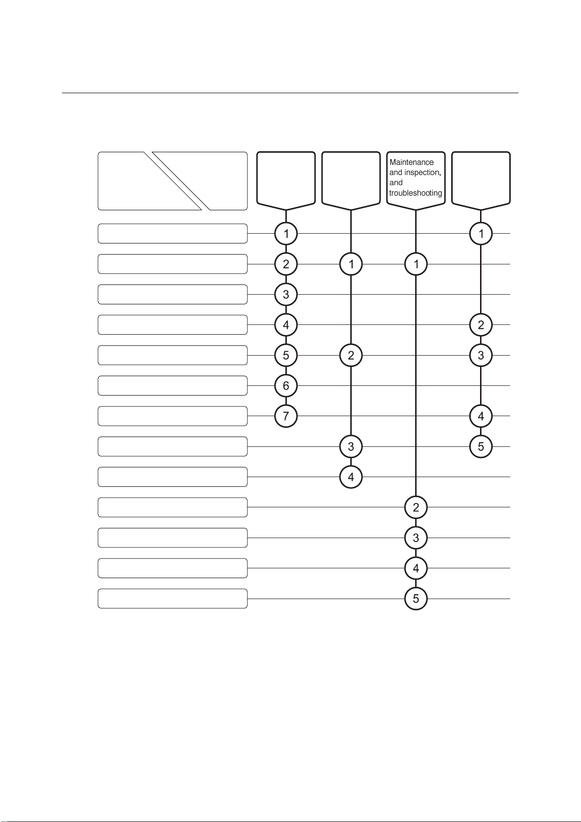
Reading Guide
Refer to the necessary sections of this instruction manual depending on your purposes such as
understanding the outline of this product or starting the product as shown below. The numbers in
circles indicate sections to be referred to in sequential order.
Purpose
Section
●Introduction
●Safety information
1. Content of Package
2. Specifications and Functions
3. Name and Function of Each Part
4. Preparations
5. Basic Operation
Start
(start-up)
Perform
respective
operations
Understand
the outline of
this product
6. How to Use the Various Functions
7. RS-232C Interface
8. Maintenance and Inspection
9. Troubleshooting
10. Transport, Storage, Disposal
11. Parts and Option List
-
5 -
Page 7

Model: TTT-710 Table of Contents
Table of Contents
●Introduction
●Safety Information
(1) Meaning of markings ⋅⋅⋅⋅ 2
(2) Safety compliance items ⋅⋅⋅⋅ 2
(3) Notes on use of the instruction manual ⋅⋅⋅⋅ 3
●Warranty
●Reading Guide
1. Content of Package
2. Specifications and Functions
······················································································· 1
········································································· 2
···························································································· 4
················································································ 5
··································································· 9
················································ 11
(1) Specifications ⋅⋅⋅⋅ 11
(2) Functions ⋅⋅⋅⋅ 13
3. Name and Function of Each Part
(1) Name of main parts ⋅⋅⋅⋅ 14
(2) Key types and functions of operation panel ⋅⋅⋅⋅ 15
4. Preparations
4.1 Installation Preparations ····································································· 16
4.2 Wiring ···························································································· 18
(1) Power cable and ground connections ⋅⋅⋅⋅ 18
(2) Connection to analytical instruments ⋅⋅⋅⋅ 19
4.3 Piping ···························································································· 25
(1) Piping diagram ⋅⋅⋅⋅ 25
(2) Pure water tank connection ⋅⋅⋅⋅ 26
(3) Waste solution tank connection ⋅⋅⋅⋅ 27
4.4 Table Plate Mounting ········································································· 30
4.5 Mounting the electrode cartridge, electrode, and titration nozzle ·················· 31
4.6 Optional Parts Connection ·································································· 35
(1) Air pump box connection ⋅⋅⋅⋅ 35
(2) Waste water valve connection ⋅⋅⋅⋅ 37
(3) Propeller stirring unit connection ⋅⋅⋅⋅ 39
(4) Reagent washing kit connection ⋅⋅⋅⋅ 40
5. Basic Operation
················································································· 16
·········································································· 46
········································ 14
5.1 Operation Screens Map ····································································· 46
5.2 Basic Operation ··············································································· 49
-
6 -
Page 8

Model: TTT-710 Table of Contents
(1) Use by connecting an automatic titrator or X Series or R Series analytical
instruments (RS-232C) ⋅⋅⋅⋅ 49
(2) Use by connecting R Series analytical instruments (OPTION2) ⋅⋅⋅⋅ 51
(3) Use by connecting acidity titrator (TA-70), salt titrator (TS-70),
or potentiometric titrator (TP-70) ⋅⋅⋅⋅ 52
(4) Use by connecting automatic burette (ABT-511) ⋅⋅⋅⋅ 54
(5) Power off ⋅⋅⋅⋅ 55
6. How to Use the Various Functions
6.1 Manual Operation ············································································· 56
(1) Arm movement and stirring operation ⋅⋅⋅⋅ 56
(2) Table plate rotation and stirring operation ⋅⋅⋅⋅ 57
(3) Stirring operation and speed adjustment ⋅⋅⋅⋅ 59
(4) Pumps and waste water valve operation and tank liquid level judgment ⋅⋅⋅⋅ 60
(5) Electrode manual washing ⋅⋅⋅⋅ 63
6.2 Various Conditions Setting ·································································· 65
(1) Number of table specimens setting ⋅⋅⋅⋅ 65
(2) Measurement conditions setting ⋅⋅⋅⋅ 66
(3) RS-232C communication conditions setting ⋅⋅⋅⋅ 67
(4) Liquid level sensor alarm setting ⋅⋅⋅⋅ 68
(5) Display contrast setting ⋅⋅⋅⋅ 69
(6) Next specimen preparatory stirring function setting ⋅⋅⋅⋅ 69
(7) Electrode washing conditions setting ⋅⋅⋅⋅ 70
7. RS-232C Interface
···································································· 74
····································· 56
7.1 Interface Specifications ······································································ 74
(1) Communication conditions ⋅⋅⋅⋅ 74
(2) Connector and pin arrangement ⋅⋅⋅⋅ 74
7.2 Message Format ·············································································· 75
(1) Receive format (PC → Turntable) ⋅⋅⋅⋅ 75
(2) Send format (Turntable → PC) ⋅⋅⋅⋅ 83
8. Maintenance and Inspection
8.1 Product Main Body Maintenance ·························································· 87
8.2 Maintenance List ·············································································· 88
8.3 Washing Water Flow Passage Maintenance and Inspection ························ 90
(1) Washing water flow passage inspection ⋅⋅⋅⋅ 90
(2) Washing water tube replacement ⋅⋅⋅⋅ 91
(3) Pure water pump replacement ⋅⋅⋅⋅ 92
8.4 Waste Solution Flow Passage Maintenance and Inspection ························ 94
(1) Waste solution flow passage inspection ⋅⋅⋅⋅ 94
(2) Waste solution hose replacement ⋅⋅⋅⋅ 95
8.5 Electrode Storage Beaker Water Level Inspection ···································· 96
8.6 Electrode Arm Maintenance and Inspection ············································ 96
(1) Electrode arm up and down operation inspection ⋅⋅⋅⋅ 96
················································· 87
-
7 -
Page 9

Model: TTT-710 Table of Contents
(2) Electrode arm position inspection and adjustment ⋅⋅⋅⋅ 96
8.7 Liquid Level Sensor Replacement ························································ 98
(1) Pure water tank liquid level sensor replacement ⋅⋅⋅⋅ 98
(2) Waste solution tank liquid level sensor replacement ⋅⋅⋅⋅ 99
9. Troubleshooting
9.1 Safety precautions when an abnormality occurred ·································· 101
9.2 Abnormality by Error Display and Countermeasures ······························· 102
9.3 Other Troubles and Countermeasures ················································· 104
9.4 System Reset Method······································································ 107
10. Transport, Storage, Disposal
10.1 Transport ······················································································ 108
10.2 Storage ························································································ 109
10.3 Disposal ······················································································· 110
11. Parts and Option List
········································································ 101
·············································· 108
······························································ 111
(Last page ⋅⋅⋅⋅ 113)
-
8 -
Page 10
Model: TTT-710 1. Content of Package
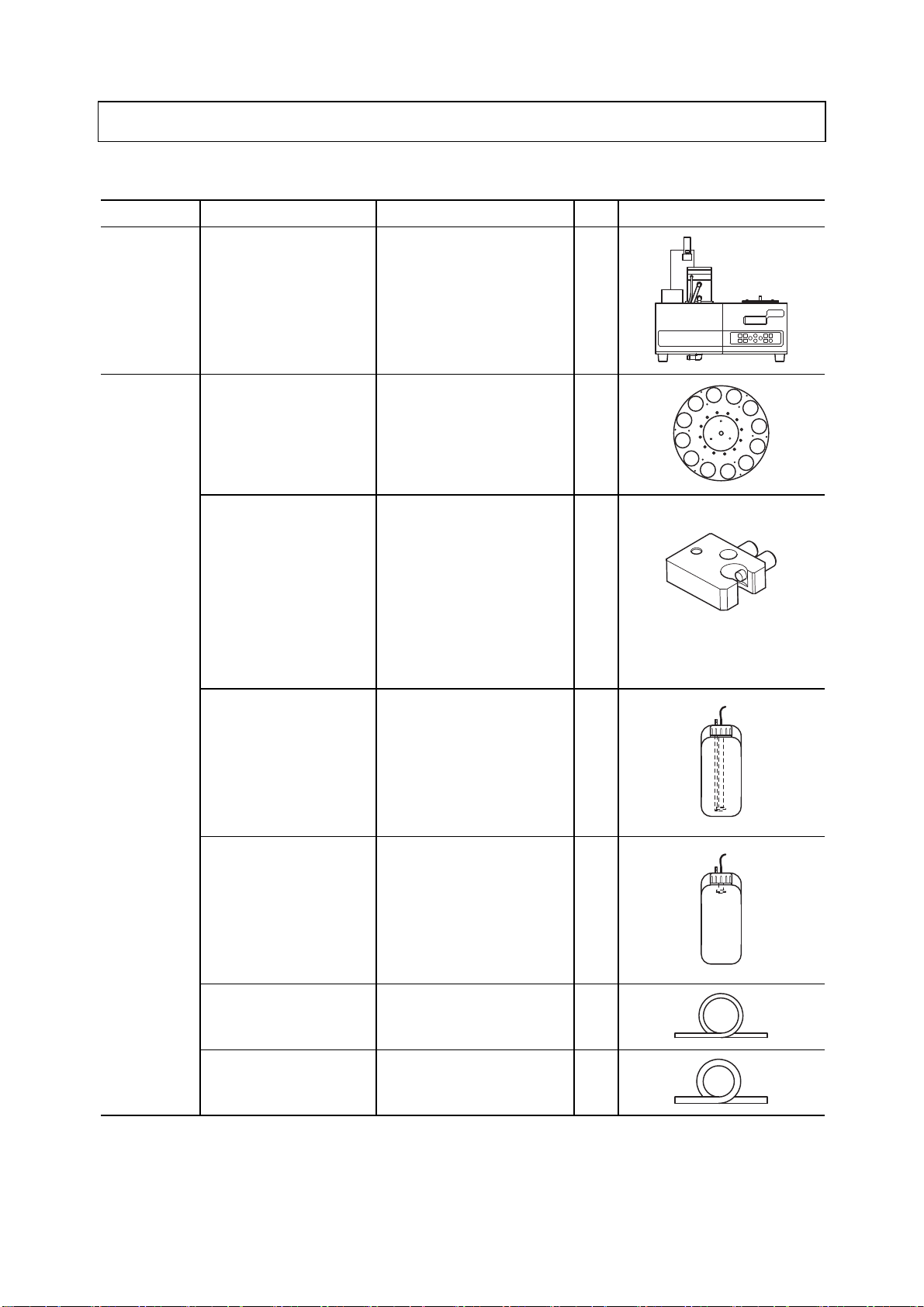
1. Content of Package
Packing List (Standard Accessories)
Classification Description Model Q’ty Appearance
Main Body Turntable TTT-710 1
Accessories Table plate*1 For 12 specimens 7401540U
For 18 specimens 7401550U
For 36 specimens 7401560U
For 60 specimens 7401570U
Electrode cartridge*2
Pure water tank (10L)
(with liquid level sensor)
7505010K(1CH cartridge 1(X))
7505020K(1CH cartridge 2(X))
7506840K(1CH cartridge 3(X))
6597970K (2CH cartridge 1)
7505030K(2CH cartridge 2(X))
6597940K (2CH cartridge 3)
6597980K (Multi cartridge)
6597990K (Sample suction
cartridge)
− 1
1
1
7505010K
(1CH cartridge 1(X))
Waste solution tank (10L)
(with liquid level sensor)
Washing water tube (3m) − 1
Waste solution hose
(1.5m)
− 1
− 1
-
9 -
(To be continued)
Page 11
Model: TTT-710 1. Content of Package
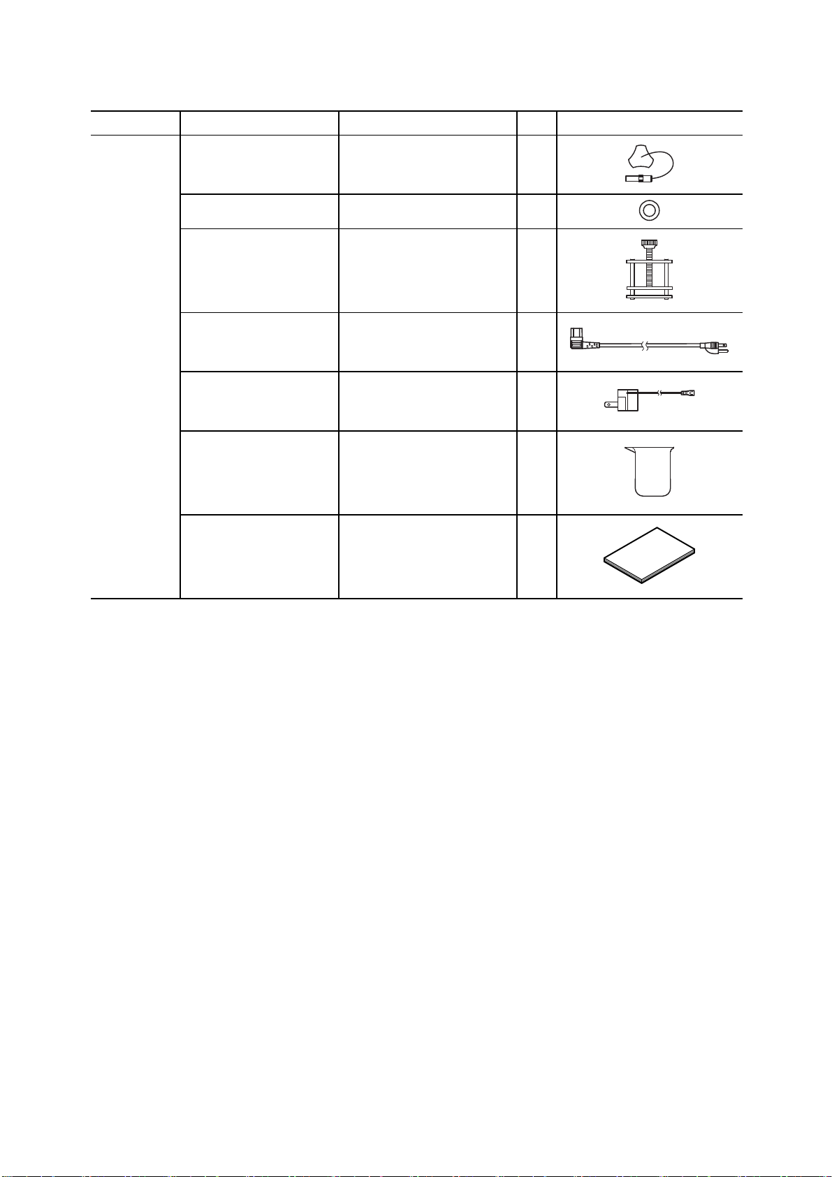
(Continued from previous page)
Classification Description Model Q’ty Appearance
Accessories End detection pin 7401630U 1
O-ring 115A006 1
Small Hoffman pinch cock 126C049 1
Power cable − 1
3P-2P adapter*3 − 1
Disposable beaker
(200mL)
Instruction manual −
136C179 1
〔NOTE〕 *1: When the product is purchased, any one kind of specified number of specimens table is
supplied
*2: When the product is purchased, any one kind of specified electrode cartridge is
supplied
*3: 3P-2P adapter may not be provided depending on the type of power cable.
-
10 -
Page 12
Model: TTT-710 2. Specifications and Functions
2. Specifications and Functions
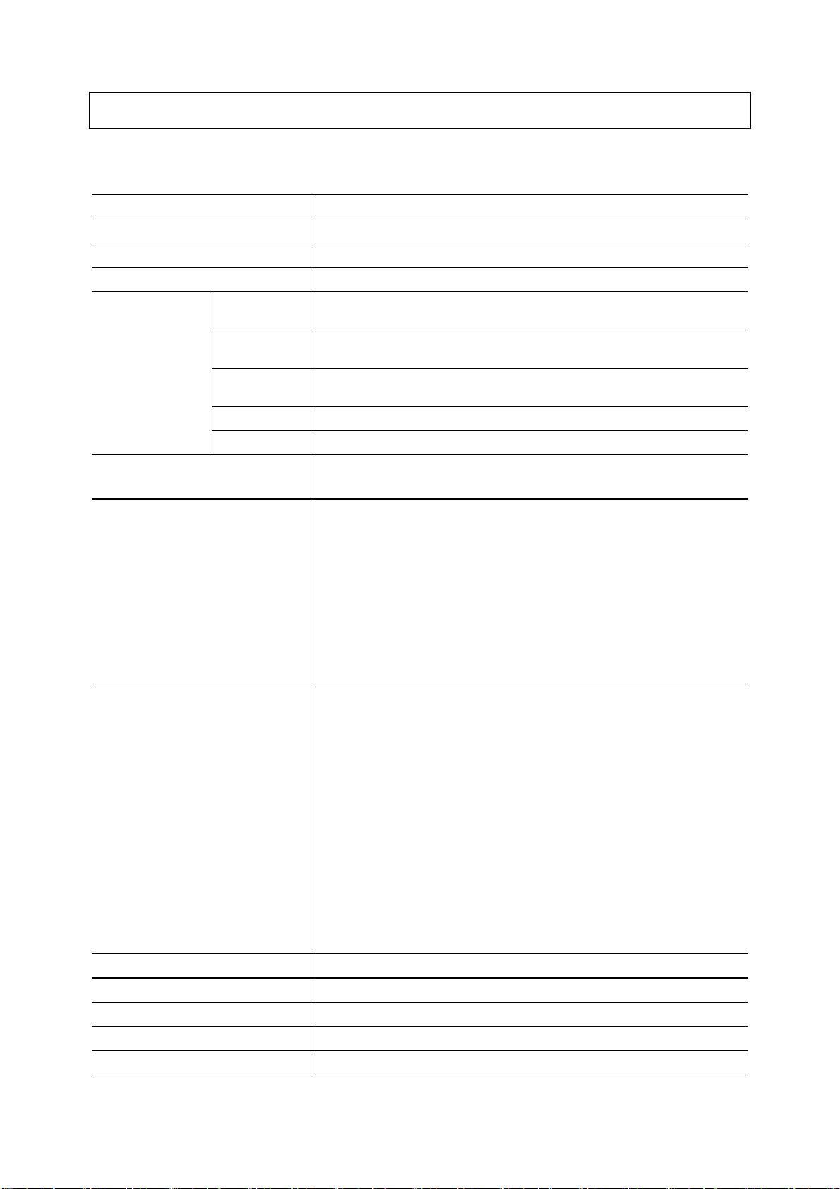
(1) Specifications
Product name Turntable
Model TTT-710
Display 20 digits x 4 lines, character LCD display
Number of table specimens 12, 18, 36, 60, 100 specimens (100 specimens table is optional)
Usage beaker size 12 specimens 200mL beaker, 300mL tall beaker
18 specimens 100mL tall beaker
36 specimens 30mL beaker, 50mL tall beaker
60 specimens 20mL dedicated beaker (NICHIDENRIKA GLASS Model H-20)
100 specimens 20mL dedicated beaker (NICHIDENRIKA GLASS Model H-20)
Stirring method
External control input/output
Washing method
(Our recommended product: AGC TECHNO GLASS or HARIO glass beaker)
(Our recommended product: AGC TECHNO GLASS or HARIO glass beaker)
(Our recommended product: AGC TECHNO GLASS glass beaker)
Standard: Magnetic stirrer method
When options connected: Propeller stirring method
RS-232C (control for Automatic titrator AUT-701/AUT-501, X Series
HM-42X/CM-42X/MM-43X, R Series HM-30R/CM-30R/MM-60R,
dedicated titrator TA-70/TS-70/TP-70)
OPTION 2 (R Series, G Series) control input/output
Automatic burette (ABT-511) / Flow analysis reference unit (FAR-201A)
control input/output
External control box control input/output
Air pump box control output
Liquid level sensor signal input (washing water 1, waste solution)
Power output for propeller stirring unit
Standard: Pure water shower washing
When options attached: Pure water bubbling washing (air pump box (with
bubbling) when waste water valve attached)
Liquid chemical shower washing (when external
signal box, reagent pump, reagent washing reservoir
attached)
Liquid chemical bubbling washing (when external
signal box, reagent pump, reagent washing reservoir,
air pump box (with bubbling), waste water valve
attached)
Pure water soak washing (when waste water valve
attached)
Liquid chemical soak washing (when external signal
box, reagent pump, reagent washing reservoir, waste
water valve attached)
Air blow (when air pump box attached)
Washing sequences 8 kinds and user washing
Washing time 0 to 9999 seconds for all washing modes
Number of air blows 1 to 9 times
Number of repetitive measurements 1 to 9 times
Measurement end detection
Detected by end detection pin or end table No. setting
-
11 -
Page 13

Model: TTT-710 2. Specifications and Functions
Washing water 1 (pure water) empty
Tank liquid level alarm
Power source 100 to 240VAC 50/60Hz
Fuse F4AH 250V (1 pc)
Waste solution full
Washing water 2 (reagent) empty (when optional liquid level sensor
connected)
Standard
Power
consumption
Main body
dimensions
Main body weight
Performance guaranteed temperature
& humidity range
When options
connected
Dimensions when
table plate not
mounted
Dimensions when
table plate mounted
Max dimensions
when operating
Max Approx. 60VA (when 100VAC used)
Max Approx. 90VA (when 240VAC used)
Max Approx. 100VA (when 100VAC used)
Max Approx. 130VA (when 240VAC used)
Approx. 440 (W) ×409 (H) × 391(D) mm
Approx. 566 (W) ×409 (H) × 507(D) mm
Approx. 566 (W) ×534 (H) × 507(D) mm
Approx. 16kg (when table plate not mounted)
Approx. 18kg (when table plate mounted)
5 to 40 ºC 20 to 85%RH (No condensation)
-
12 -
Page 14

Model: TTT-710 2. Specifications and Functions
(2) Functions
Manual operation • Arm movement (up/down and left/right)
• Table rotation (movement to next specimen No., movement to specified No.
movement to home position)
• Stirring operation (ON/OFF and speed adjustment)
• Pump (pure water pump, air pump, reagent pump) and waste water valve
open/close operation
• Tank liquid level judgment (pure water tank, reagent tank, waste solution
tank)
• Washing sequence (pure water shower, pure water bubbling, reagent shower,
reagent bubbling, pure water soak, reagent soak, air blow)
• Electrode washing by washing mode
Conditions setting • Measurement start table No. (1 to number of specimens of each table plate)
• Measurement end table No. (1 to number of specimens of each table plate
and endless)
• Number of repetitive measurement (1 to 9 times)
• Stirring time before measurement (0 to 9999 seconds)
• Wait time before measurement (0 to 9999 seconds)
• End buzzer time (0 to 9999 seconds)
RS-232C interface Standard equipment
Communication conditions
Baud rate (Selected from among 300, 600, 1200, 2400, 4800, and 9600bps)
Data length (Selected from 7 and 8Bit)
Parity (Selected from NONE, ODD, EVEN)
Stop bit (Selected from 1 and 2Bit)
Liquid level sensor Enable/disable settable
Display Adjustable contrast
Next specimen preparatory stirring Enable/disable settable (Enable for only next specimen stirring specifications)
-
13 -
Page 15
Model: TTT-710 3. Name and Function of Each Part
3. Name and Function of Each Part
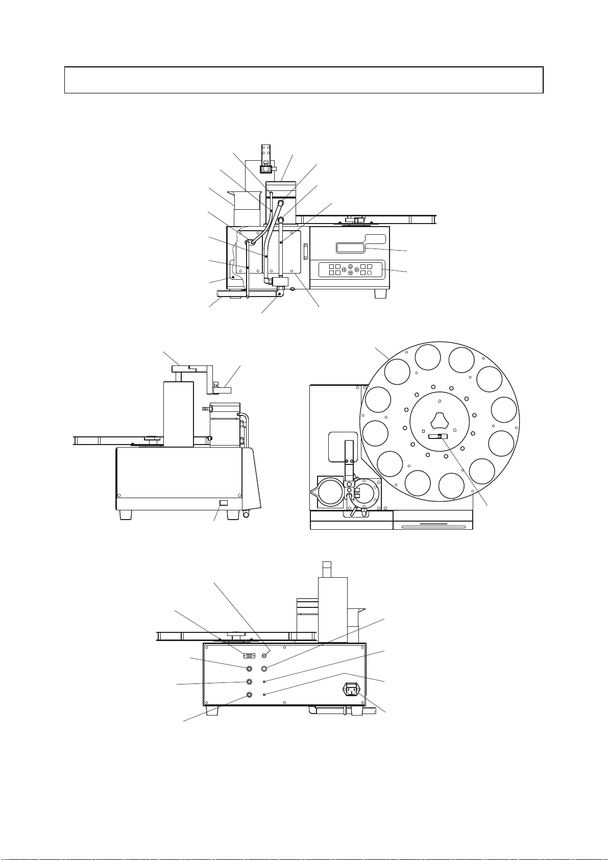
(1) Name of main parts
Pure water supply port
Washing water tube
(for washing reservoir)
Electrode storage beaker
Pure water pump
Waste solution hose
(for overflow port)
Washing water tube (for pump)
Piping cover
Waste solution hose
(for outlet 2)
Electrode arm
Waste solution outlet 2
Washing reservoir
Overflow port
Waste solution outlet 1
Waste solution hose (for outlet 1)
Display
Operation panel
Waste water valve attaching port
<Front side>
Table plate
Electrode cartridge
Power switch
(|: power ON ○: power OFF)
<Left side>
Upper stirring unit connection connector
(TO STIRR.)
RS-232C connection connector
(RS-232C)
R/G Series connection connector
(EXT. SIG. OPTION2)
External signal box connection
connector
(EXT. SIG. BOX)
ABT/FAR connection connector
(EXT. SIG. FAR-201A/ABT-511)
<Back side>
Name of Main Parts
End detection pin
<Top side>
Air pump box connection connector
(TO AIR PUMP)
Liquid level sensor connection connector
(for pure water)
(LEVEL ALARM RINSE 1)
Liquid level sensor connection connector
(for waste solution)
(LEVEL ALARM DRAIN)
Power inlet (with fuse)
(~100-240V 130VA FUSE F4AH250V)
-
14 -
Page 16
Model: TTT-710 3. Name and Function of Each Part
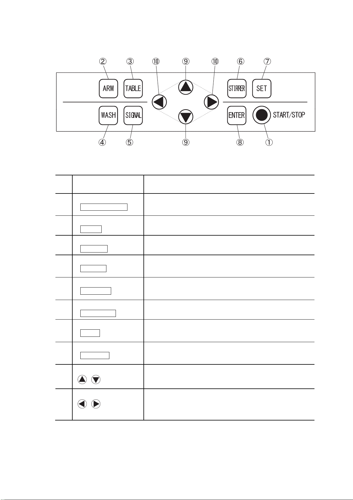
(2) Key types and functions of operation panel
Operation Panel
Key Types and Functions of Operation Panel
No.
① START/STOP key
Type of key
(Notation in text)
( START/STOP )
② ARM key
( ARM )
③ TABLE key
( TABLE )
④ WA S H k e y
( WASH )
⑤ SIGNAL key
( SIGNAL )
⑥ STIRRER key
( STIRRER )
⑦ SET key
( SET )
⑧ ENTER key
( ENTER )
Functions
• Performs continuous measurement start or force-quit during
measurement.
(Other than RS-232C communication)
• Switches to the arm manual operation screen.
• Switches to the table manual operation screen.
• Switches to the washing conditions setup and manual washing
operation screen.
• Switches to each operation signal confirmation screen.
• Starts or ends manual stirring operation.
• Switches to the setup screen of each measurement condition.
• Enters each condition set value.
• Performs manual washing or each operation signal confirmation.
⑨ Up and down keys
( )
⑩ Left and right keys
( )
• Changes values (increment/decrement) and switches the setting item
selection.
• Performs arm up/down operation during manual operation.
• Switches the setting item selection.
• Performs arm left and right operation during manual operation, table
rotation operation, and stirring speed adjustment.
-
15 -
Page 17
Model: TTT-710 4.1 Installation Preparations
4. Preparations
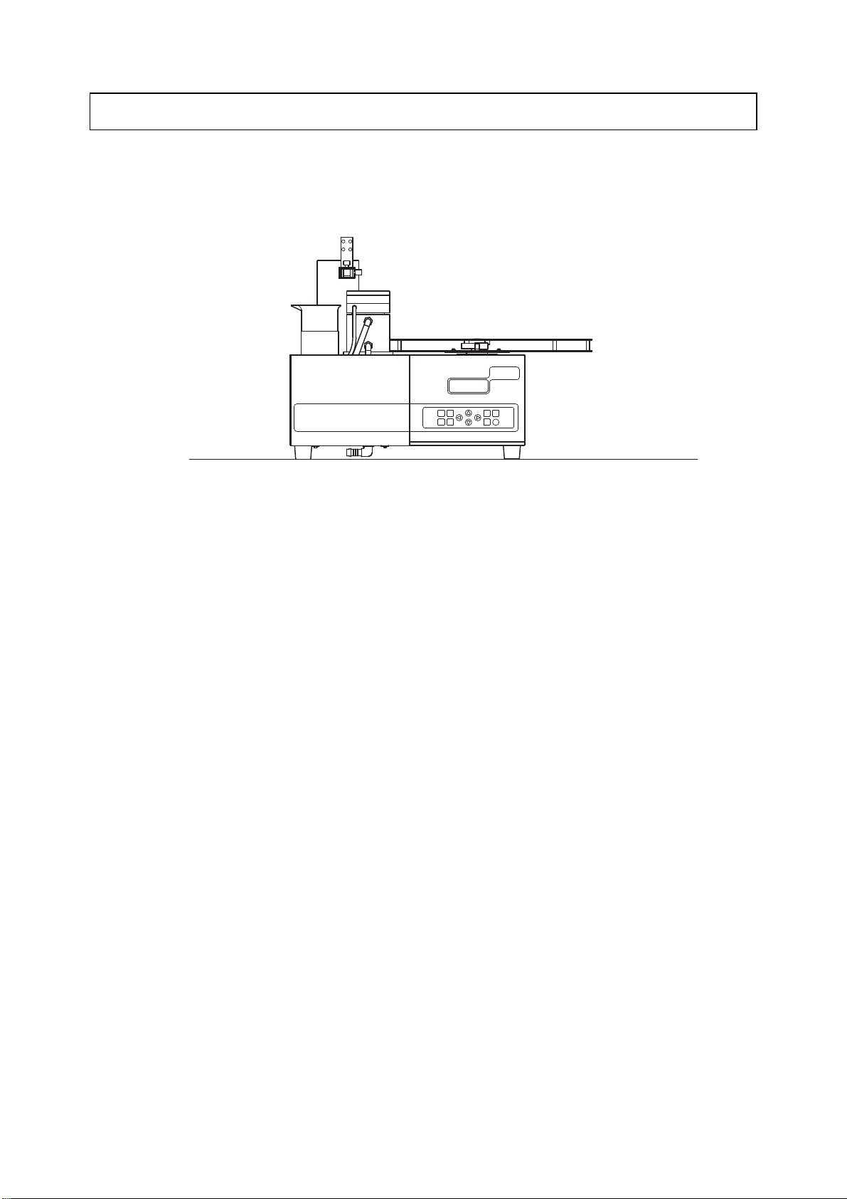
4.1 Installation Preparations
Install the product main body at a flat place.
Provide an empty space of the following dimensions as installation space for the product main body
and the analytical instruments to be connected.
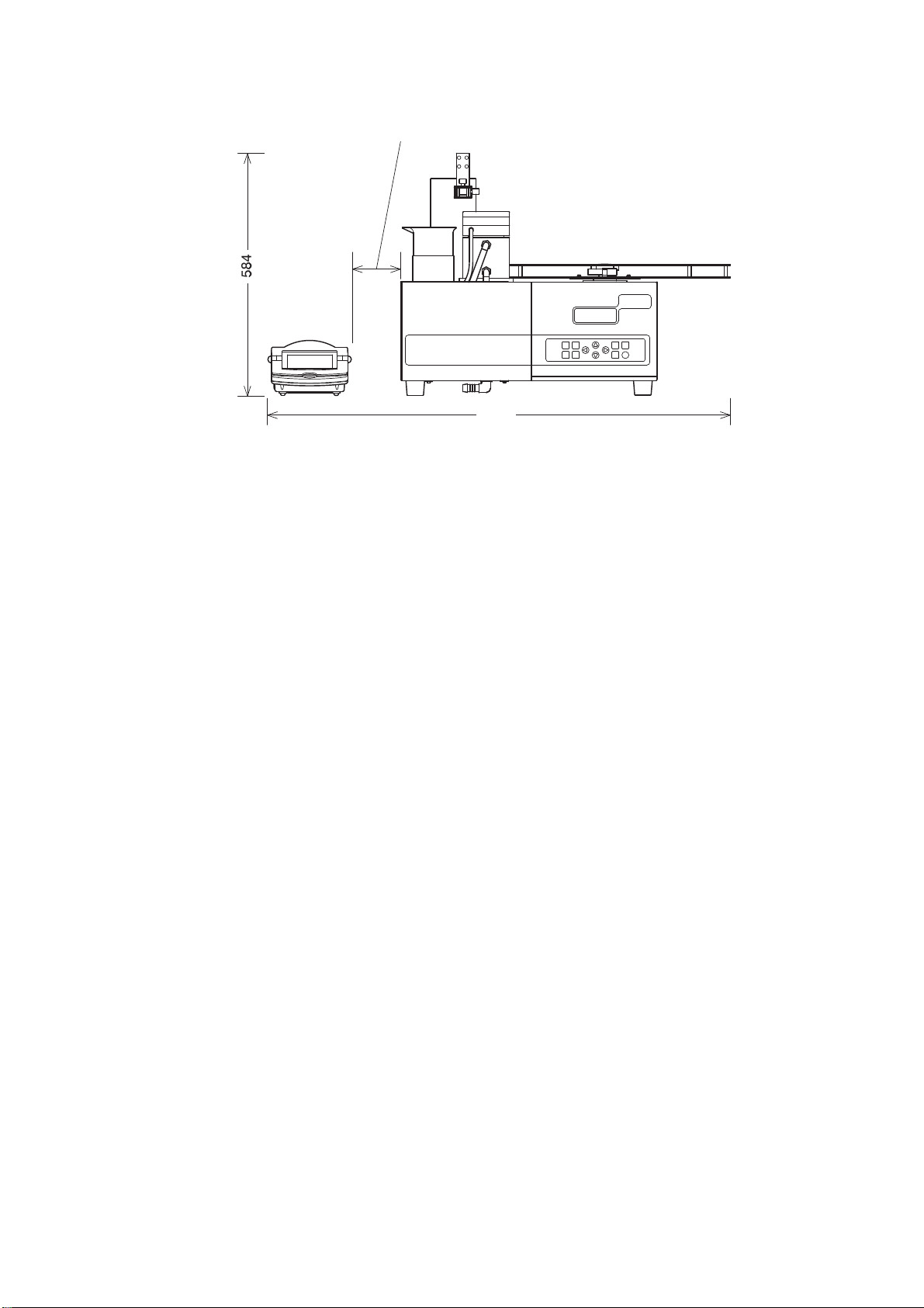
• When using with X Series analytical instruments ⋅⋅⋅⋅ 896 (W) × 584 (H) × 557 (D) mm
• When using with R Series analytical instruments ⋅⋅⋅⋅ 918 (W) × 584 (H) × 557 (D) mm
• When using with G Series analytical instruments ⋅⋅⋅⋅ 948 (W) × 584 (H) × 557 (D) mm
• When using with Automatic Titrator AUT-701 (including Titration Burette ABT-7 1 unit)
⋅⋅⋅⋅ 1076 (W) × 584 (H) × 557 (D) mm
• When using with Automatic Titrator AUT-501 (including Titration Burette ABT-511 1 unit)
⋅⋅⋅⋅ 1126 (W) × 584 (H) × 557 (D) mm
• When using with dedicated Titrator TA-70, TS-70, or TP-70
⋅⋅⋅⋅ 876 (W) × 584 (H) × 557 (D) mm
• When using with Automatic Burette ABT-511 ⋅⋅⋅⋅ 886 (W) × 584 (H) × 557 (D) mm
Also provide an empty space of 100mm (10cm) or more between the product main body left side and
the analytical instrument or a wall to turn on or off the power easily.
-
16 -
Page 18
Model: TTT-710 4.1 Installation Preparations
Provide an empty space of 100mm or more.
918
Example of Installation Combined with R Series Analytical Instruments
-
17 -
Page 19
Model: TTT-710 4.2 Wiring
4.2 Wiring
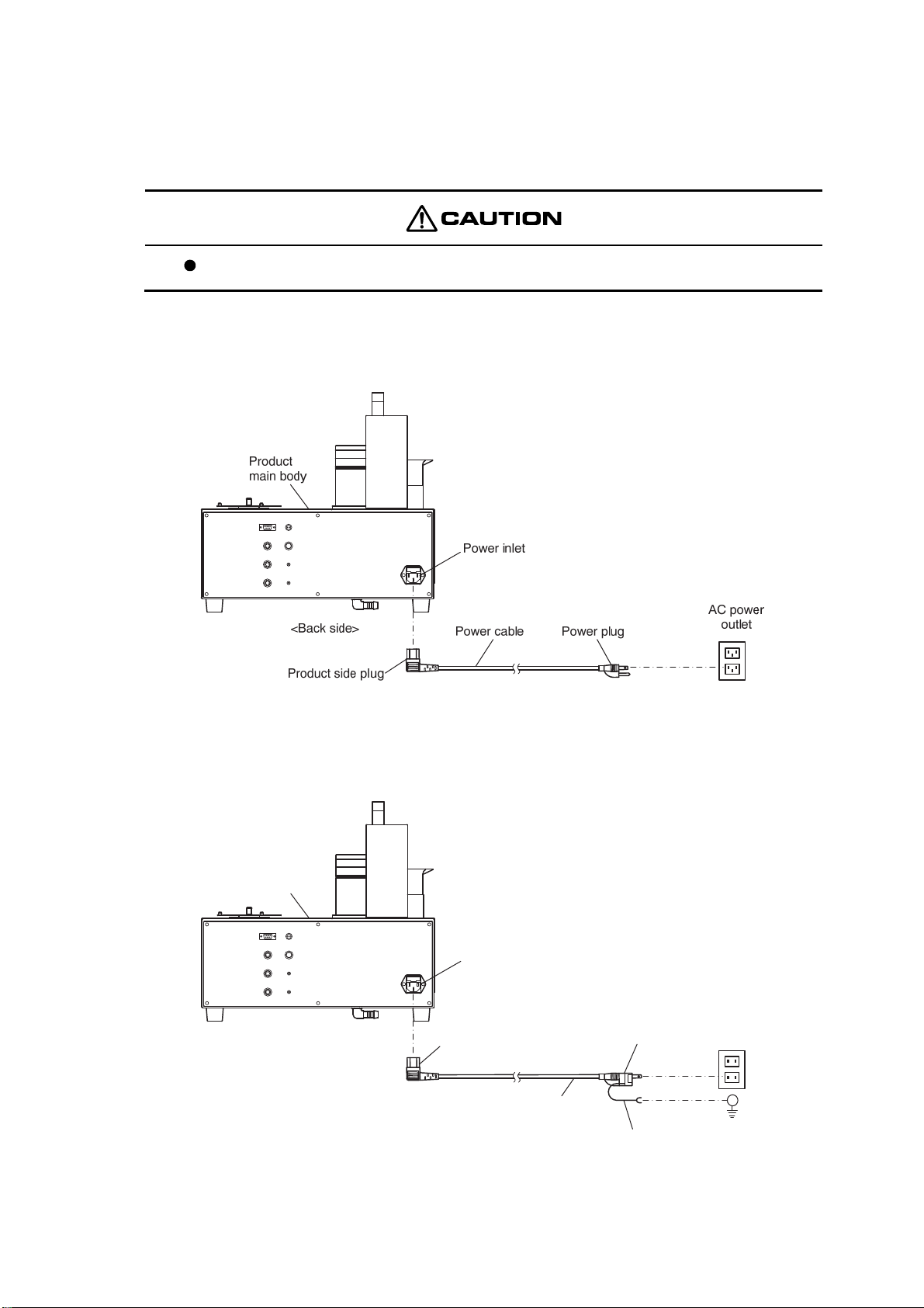
(1) Power cable and ground connections
Never use a power cable and 3P-2P adapter other than the accessories.
(a) Confirm that the power switch on the left-hand side of the product main body is off (OFF) and
connect the product side plug of the accessory power cable to the power inlet on the back side of
the main body. Connect the plug at the other end of the power cable to an AC power outlet.
Power Cable and Ground Connections
(b) When the power plug cannot be connected to 3-pin outlet, connect the accessory 3P-2P adapter to
the power cable and connect it to an AC power outlet. Also connect the 3P-2P adapter ground wire
to a ground line. (When accessory 3P-2P adapter is provided)
Product
main body
Power inlet
AC power
<Back side>
Product side plug
3P-2P adapter
Power cable
outlet
Ground wire
Power Cable and Ground Connections
(When power plug cannot be connected to 3-pin outlet)
-
18 -
Ground line
Page 20
Model: TTT-710 4.2 Wiring
(2) Connection to analytical instruments
The analytical instruments that can be used with the product main body are listed in the table below.
Refer to (a) to (i) and connect the cable corresponding to the analytical instruments to be used.
Connectable Analytical Instruments and Cable Connection Method
Connectable analytical instruments,
etc.
X Series analytical instruments
(HM-42X, CM-42X, MM-43X)
R Series analytical instruments
(HM-30R, CM-30R, MM-60R)
G Series analytical instruments
(HM-50G, HM-60G, CM-40G, CM-60G,
IM-55G, WM-50EG)
Automatic titrator (AUT-701) >> 4.2(2) (e) “Connection to automatic titrator (AUT-701)”
Automatic titrator (AUT-501) >> 4.2(2) (f) “Connection to automatic titrator (AUT-501)”
Acidity titrator (TA-70) >> 4.2(2) (g) “Connection to dedicated titrator (TA-70, others)”
Salt titrator (TS-70)
Potentiometric titrator (TP-70)
Automatic burette (ABT-511) >> 4.2(2) (h) “Connection to automatic burette (ABT-511)”
Flow analysis reference unit
(FAR-201A)
Personal computer (PC) >> 4.2(2) (j) “Connection to personal computer (PC)”
Cable connection method (reference item)
>> 4.2(2) (a) “Connection to X Series analytical instruments
(HM-42X, others)”
>> 4.2(2) (b) “Connection to R Series analytical instruments
(HM-30R, others) (RS-232C connection)”
>> 4.2(2) (c) “Connection to R Series analytical instruments
(HM-30R, others) (OPTION2 connection)”
>> 4.2(2) (d) “Connection to G Series analytical instruments
(HM-50G, others)”
>> 4.2(2) (i) “Connection to flow analysis reference unit
(FAR-201A)”
(a) Connection to X Series analytical instruments (HM-42X, others)
Connect the RS-232C connection connector of product main body and the RS-232C connection
connector of X Series analytical instruments (HM-42X, others) using the turntable connection
RS-232C cable (optional).
RS-232C connection connector
(RS-232C)
<Back side>
Product main body
Turntable connection RS232C cable
(Part code No.: 7433040K)
X Series analytical instruments
(HM-42X, CM-42X, MM-43X)
<Left side>
RS-232C connection
connector
(EXT.I/O)
Connecting to X Series Analytical Instruments (HM-42X, others)
-
19 -
Page 21
Model: TTT-710 4.2 Wiring
(b) Connection to R Series analytical instruments (HM-30R, others) (RS-232C
connection)
Connect the RS-232C connection connector of product main body and the RS-232C connection
connector of R Series analytical instruments (HM-30R, others) using the TTT connection 232C cable
(optional).
RS-232C connection connector
(RS-232C)
<Back side>
Product main body
<Left side>
TTT connection 232C cable
(Part code No.: 118C087)
R Series analytical instruments
(HM-30R, CM-30R, MM-60R)
RS-232C connection
connector
Connecting to R Series Analytical Instruments (HM-30R, others) (RS-232C connection)
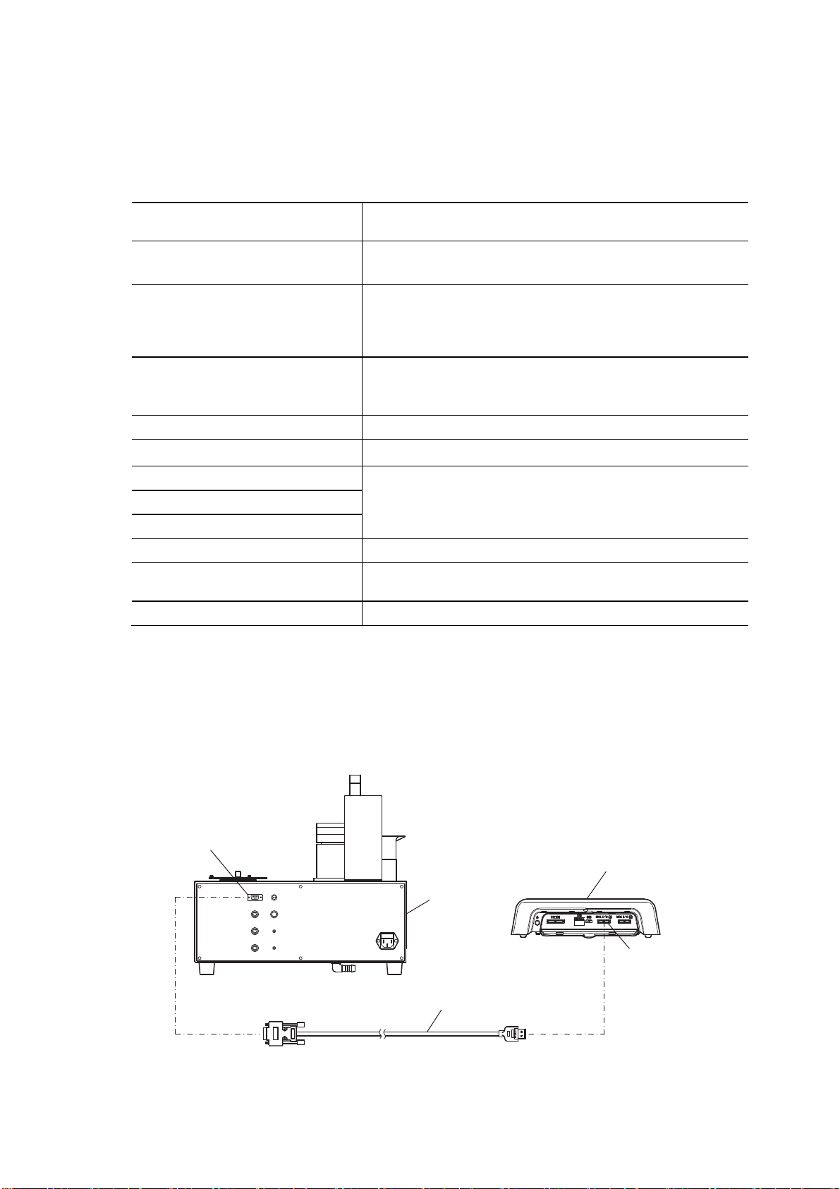
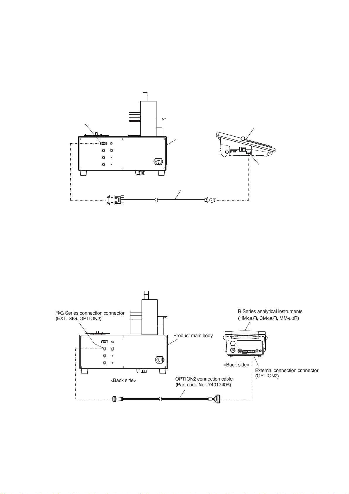
(c) Connection to R Series analytical instruments (HM-30R, others) (OPTION2
connection)
Connect the R/G Series connection connector of product main body and the external connection
connector (OPTION 2) of R Series analytical instruments (HM-30R, others) using the OPTION 2
connection cable (optional).
Connecting to R Series Analytical Instruments (HM-30R, others) (OPTION2 connection)
-
20 -
Page 22
Model: TTT-710 4.2 Wiring
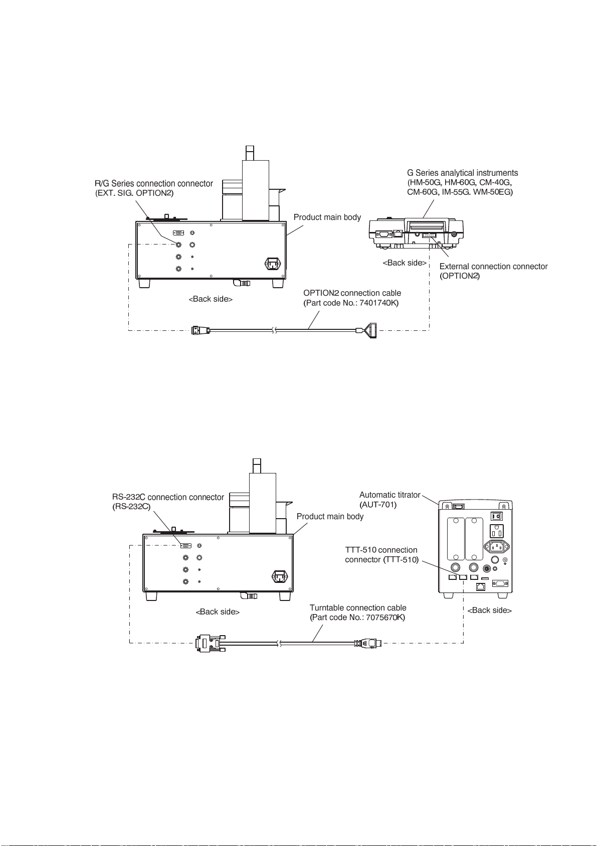
(d) Connection to G Series analytical instruments (HM-50G, others)
Connect the R/G Series connection connector of product main body (EXT. SIG. OPTION2) and the
external connection connector (OPTION 2) of G Series analytical instruments (HM-50G, others) using
the OPTION 2 connection cable (optional).
Connecting to G Series Analytical Instruments (HM-50G, others)
(e) Connection to automatic titrator (AUT-701)
Connect the RS-232C connection connector of product main body and the TTT-510 connection
connector of automatic titrator (AUT-701) using the turntable connection cable (optional).
Connecting to Automatic Titrator (AUT-701)
-
21 -
Page 23
Model: TTT-710 4.2 Wiring
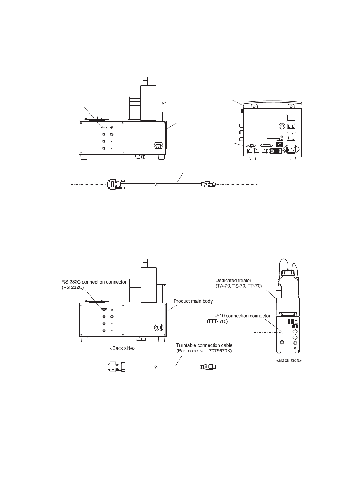
(f) Connection to automatic titrator (AUT-501)
Connect the RS-232C connection connector of product main body and the TTT-3100 connection
connector of automatic titrator (AUT-501) using the RS-232C cable (optional).
RS-232C connection connector
(RS-232C)
<Back side>
Product main body
RS-232C cable
(Part code No.: 0GC00006)
Automatic titrator
(AUT-501)
TTT-3100 connection
connector (TTT-3100)
Connecting to Automatic Titrator (AUT-501)
(g) Connection to dedicated titrator (TA-70, others)
Connect the RS-232C connection connector of product main body and the TTT-510 connection
connector of dedicated titrator (TA-70, others) using the turntable connection cable (optional).
<Back side>
Connecting to Dedicated Titrator (TA-70, others)
-
22 -
Page 24
Model: TTT-710 4.2 Wiring
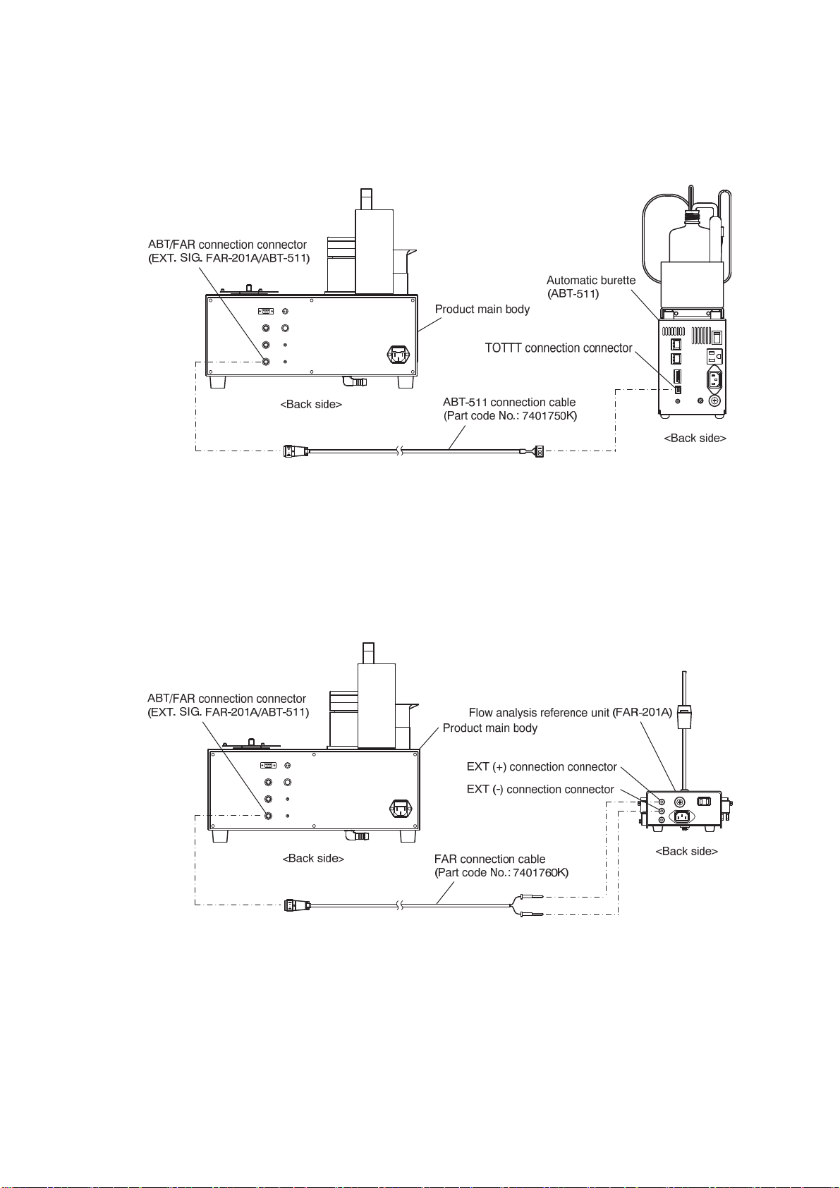
(h) Connection to automatic burette (ABT-511)
Connect the ABT/FAR connection connector of product main body and the TOTTT connection
connector of automatic burette (ABT-511) using the ABT-511connection cable (optional).
Connection to Automatic Burette (ABT-511)
(i) Connection to flow analysis reference unit (FAR-201A)
Connect the ABT/FAR connection connector of product main body and the EXT (+) and EXT (-)
connection connector of flow analysis reference unit (FAR-201A) using the FAR connection cable
(optional).
Connecting to Flow Analysis Reference Unit (FAR-201A)
-
23 -
Page 25
Model: TTT-710 4.2 Wiring
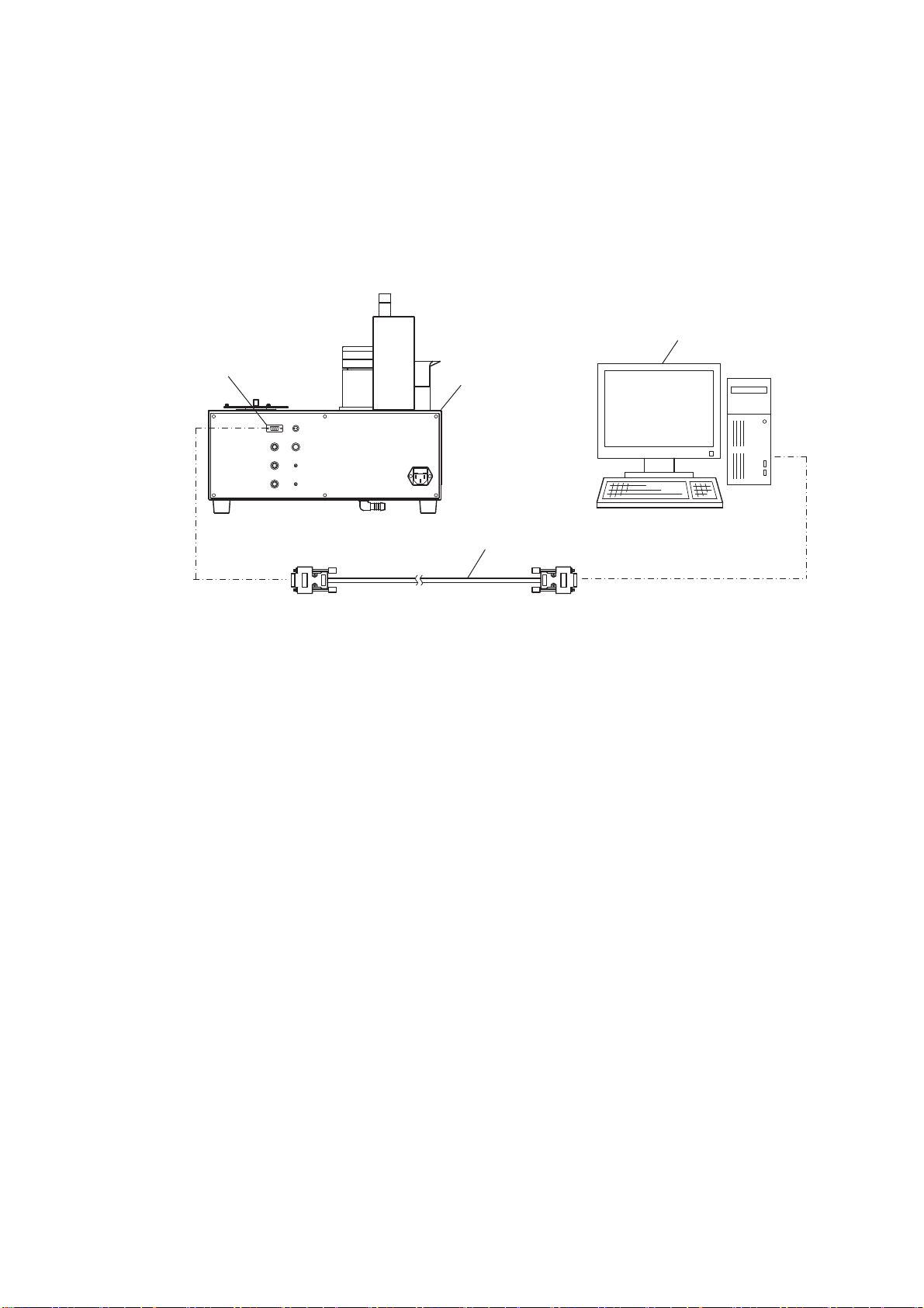
(j) Connection to personal computer (PC)
(a) The connection cable is different depending on the connector of the PC to be used. Refer to the PC
instruction manual and connect the RS-232C connection connector of product main body and the
PC connector using a suitable cable (straight type).
(b) When the PC uses a D-sub 9 pin connector, RS-232C cable (part No.:0GC00002) is available as a
DKK-TOA option. If the PC does not have RS-232C port, purchase and use USB-RS232C adapter
(manufacturer: MOXA, Part code: UPort 1150I) as a recommended part.
PC
RS-232C connection connector
(RS-232C)
Product main body
<Back side>
RS-232C straight cable, etc.
To PC side connector
Connecting to Personal Computer (PC)
-
24 -
Page 26
Model: TTT-710 4.3 Piping
4.3 Piping
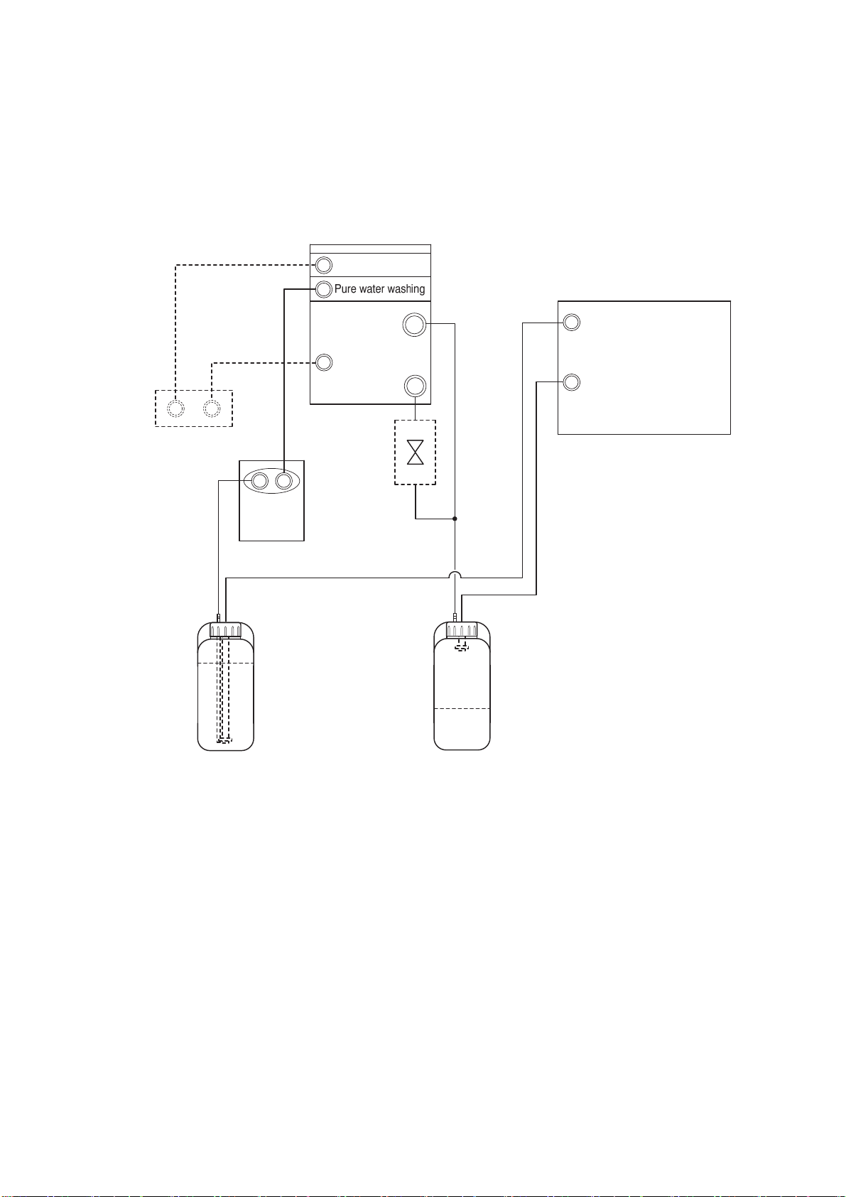
(1) Piping diagram
The pure water tank and waste solution tank piping diagram is shown below. The areas of dotted
lines are optional specifications.
Washing reservoir
Air blow
Product back side
Air pump
box
Overflow
Air bubbling
Drain
Waste water
valve
Pure water pump
Liquid level sensor
connection connector
(for pure water)
(LEVEL ALARM RINSE1)
Liquid level sensor
connection connector
(for waste solution)
(LEVEL ALARM DRAIN)
Pure water
tank
Waste
solution tank
Piping Diagram
-
25 -
Page 27
Model: TTT-710 4.3 Piping
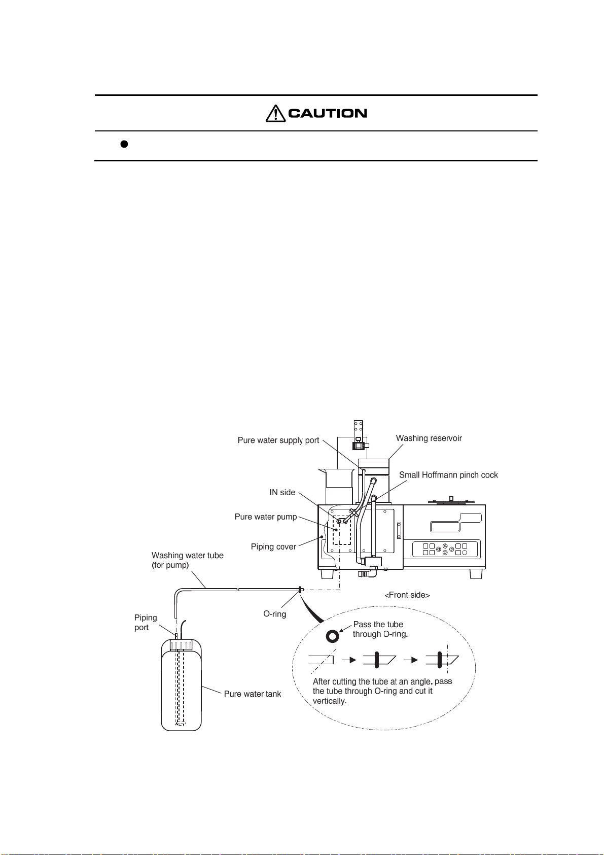
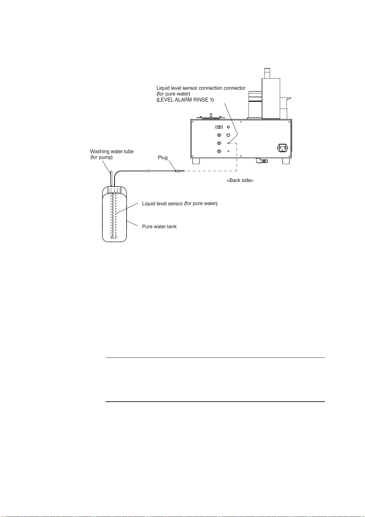
(2) Pure water tank connection
Be sure that liquid chemical is not sucked into the pure water pump.
① Install the pinch cock. ⋅⋅⋅⋅⋅⋅ Install the accessory small Hoffmann pinch cock to the pipe between
② Fill the tank with pure water ⋅⋅⋅⋅⋅⋅ Prepare the accessory 10L tank as the pure water tank by
③ Cut the tube. ⋅⋅⋅⋅⋅⋅ Use cutters, etc. to cut the accessory washing water tube (part code: 116E049)
④ Pass the tube through O-ring. ⋅⋅⋅⋅⋅⋅ Pass one end of the washing water tube (for pump)
the pure water pump and the washing reservoir pure water supply port. The amount of pure water
supplied to the washing reservoir can be adjusted by how this pinch coke is tightened.
filling at least half full of pure water.
to a suitable length matching the distance between the IN side of the pure water pump at the front
of the main body and the pure water tank to be installed and use the tube as the washing water tube
(for pump).
prepared at step ③ through the accessory O-ring.
⑤ Connect the tube. ⋅⋅⋅⋅⋅⋅ Remove the product main body piping cover forward and connect one
end (O-ring side) of the washing water tube (for pump) to the IN side of the pure water pump and
fix it with the O-ring. Connect the other end of the washing water tube to the pure water tank
piping port.
Connecting the Washing Water Tube to the Pure Water Punp
-
26 -
Page 28
Model: TTT-710 4.3 Piping
⑥ Insert the plug. ⋅⋅⋅⋅⋅⋅ Insert the plug of liquid level sensor into the liquid level sensor connection
connector (for pure water) (LEVEL ALARM RINSE 1) of the product main body.
Inserting the Plug of Liquid Level Sensor (for pure water)
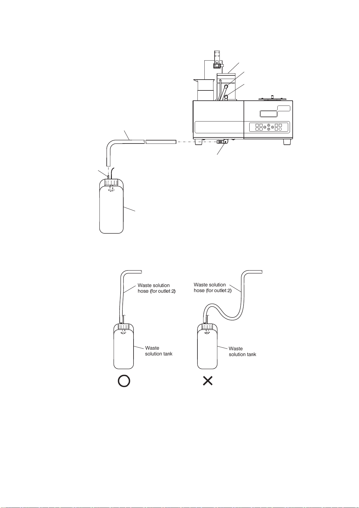
(3) Waste solution tank connection
① Cut the waste solution hose. ⋅⋅⋅⋅⋅⋅ Use a hose cuter, etc. to cut the accessory waste solution
hose (part code: XD701500) to a suitable length matching to the distance between waste solution
outlet 2 of product main body and the waste solution tank to be used and use the hose as the waste
solution hose (for outlet 2).
② Connect the waste solution hose. ⋅⋅⋅⋅⋅⋅ Connect one end of the waste solution hose (for outlet
2) prepared at step ① to waste solution outlet 2 of product main body and the other end to the
waste solution tank piping port.
【IMPORTANT】 • Install the waste solution tank at a place sufficiently lower than the
product main body. Also be sure that the waste solution hose (for outlet 2)
is straight from top to bottom. If the hose is installed at a high place or is
bent midway between top and bottom, the waste solution will collect in the
hose and will not flow into the waste solution tank.
-
27 -
Page 29
Model: TTT-710 4.3 Piping
Washing reservoir
Overflow port
Waste solution outlet 1
Waste solution hose (for outlet 2)
Waste solution outlet 2
Piping
port
Waste solution tank
<Front side>
Connecting the Waste Solution Hose (for outlet 2)
Correct Method of Piping the Waste Solution Hose
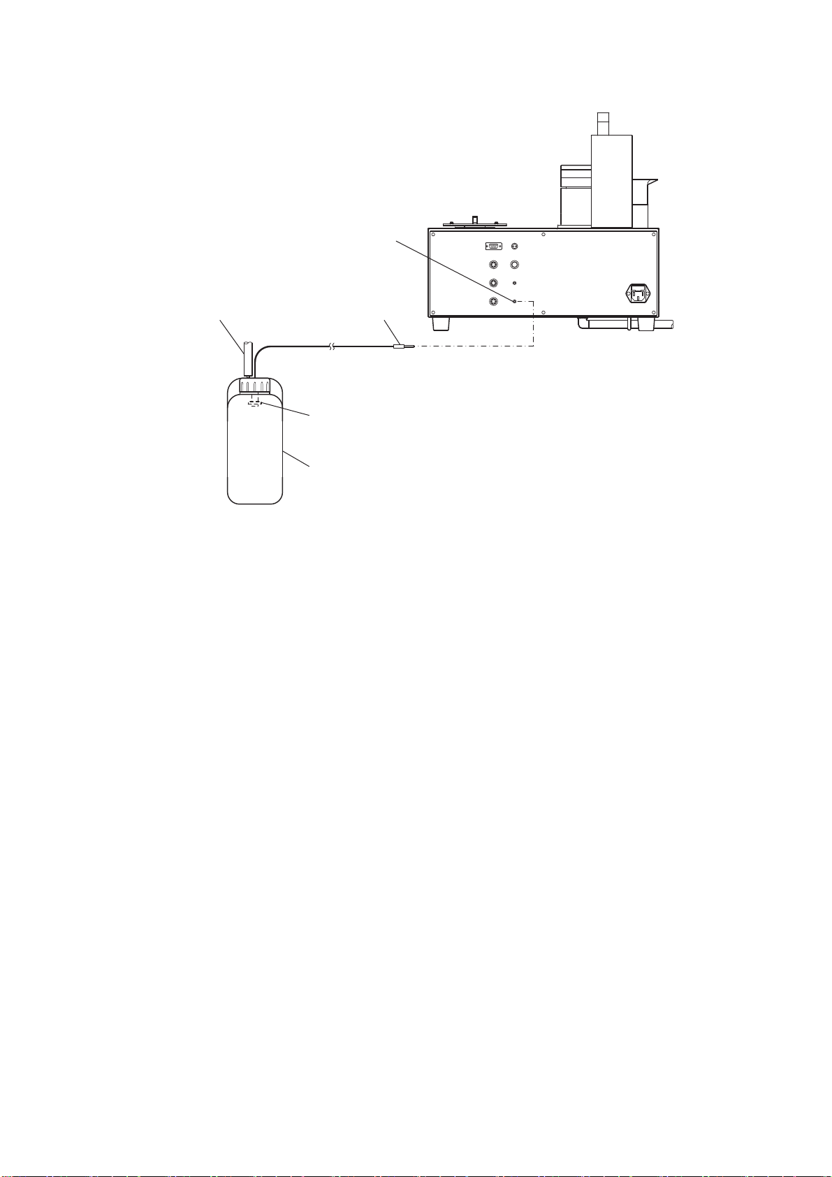
③ Insert the plug. ⋅⋅⋅⋅⋅⋅ Insert the plug of the liquid level sensor into the liquid level sensor
connection connector (for waste solution) of the product main body.
-
28 -
Page 30
Model: TTT-710 4.3 Piping
Liquid level sensor connection connector
(for waste solution)
(LEVEL ALARM DRAIN)
Waste solution hose
(for outlet 2)
Liquid level sensor (for waste solution)
Plug
<Back side>
Waste solution tank
Inserting the Plug of the Liquid Level Sensor (for waste solution)
-
29 -
Page 31

Model: TTT-710 4.4 Table Plate Mounting
4.4 Table Plate Mounting
① Set the table plate on the holder. ⋅⋅⋅⋅⋅⋅ Place the table plate on the table holder plate so that the
holes (3 places) in the accessory table plate match the pins (3 places) of the product main body
table holder plate.
Product main body
Table holder plate
<Top side>
Setting the Table Plate on the Table Holder Plate
② Fix the table plate. ⋅⋅⋅⋅⋅⋅ Fix the table plate by tightening the table plate fixing cap nut connected
to the end detection pin from the top of the table plate.
③ Fix the end detection pin. ⋅⋅⋅⋅⋅⋅ Fix the end detection pin to the end detection pin holder of the
table plate.
Pins (3 places)
Table plate
Holes (3 places)
Fixing the Table Plate
-
30 -
Page 32

Model: TTT-710 4.5 Mounting the electrode cartridge, electrode, and titration nozzle
4.5 Mounting the electrode cartridge, electrode, and titration
nozzle
The electrode cartridge is different depending on the number of table plate specimens, kind of
electrode used, and the number of titration nozzles used. Use the electrode corresponding to the
application. >> “Types of Electrode Cartridge Table”
Mounting the Electrode Cartridge, Electrode, and Titration Nozzle
① Mount the electrode cartridge. ⋅⋅⋅⋅⋅⋅ After loosening the knurled knob at the end of the
electrode arm of the product main body, hold the electrode cartridge with the dent facing upward
and insert the cartridge into the end of the electrode arm and fix it by tightening the knurled knob.
② Mount the electrode and titration nozzle. ⋅⋅⋅⋅⋅⋅ Loosen the electrode fixing bolt of the
electrode cartridge, insert the electrode and titration nozzle to be used, and fix the electrode by
tightening the electrode fixing bolt. (The electrode cartridge accessory adapter may be necessary
depending on the electrode to be used. Refer to the “Types of Electrode Cartridge table” and
“Usable Electrode Type Classification Table” for the adaptors corresponding to the electrodes
used.)
③ Clamp the cable, etc. ⋅⋅⋅⋅⋅⋅ Clamp the electrode cable and the tube from the titration nozzle with
the clamp at the top of the electrode arm.
-
31 -
Page 33

Model: TTT-710 4.5 Mounting the electrode cartridge, electrode, and titration nozzle
Types of Electrode Cartridges Table
Name
(Number of mountable
electrodes and nozzles)
1CH cartridge 1(X)
(Electrode:1 Nozzle: 1)
1CH cartridge 2(X)
(Electrode:1 Nozzle: 2)
1CH cartridge 3(X)
(Electrode:1)
2CH cartridge 1
(Electrode:2 Nozzle: 1)
*
1
*
3
Model
7505010K
7505020K
7506840K
6597970K
Number of
usable table
specimens
All number of
specimens
12 specimens
18 specimens
36 specimens
All number of
specimens
12 specimens
18 specimens
36 specimens
Usable electrode type
X
R
J (white adapter use)
X
R
J (white adapter use)
X
R
J (White adapter use)
J
ION (silver adapter
use)
*
2
Appearance
X
2CH cartridge 2(X)
(Electrode:2)
7505030K
12 specimens
18 specimens
36 specimens
R
J (white adapter use)
ION (silver adapter
use)
X
2CH cartridge 3
(Electrode:2 Nozzle: 2)
6597940K
12 specimens
18 specimens
R
J (white adapter use)
ION (silver adapter
use)
J (max. 2)
Multi cartridge
(Electrode: 4 Nozzle: 4)
6597980K 12 specimens
ION (2)
(Up to 4 can be
mounted by using the
silver adapter)
Sample suction cartridge
(Nozzle: 1)
6597990K
All number of
specimens
−
Nozzle
*1: A temperature sensor can be installed by using the accessory blue adapter at the nozzle mounting hole.
However, with 1CH cartridge 1(X), it can be used only when the 12, 18, or 36 specimens tables are used.
*2: Electrode types “X, R, J, or ION” described in the table indicate the usable electrode type classification. For details,
refer to the Usable Electrode Type Classification Table.
*3: When 60 or 100 specimens table is used, only the micro titration nozzle (AST-P008) can be mounted.
-
32 -
Page 34

Model: TTT-710 4.5 Mounting the electrode cartridge, electrode, and titration nozzle
Usable Electrode Type Classification Table
Electrode type (X) Electrode type (R)
Name Model Name Model Name Model
GST-5841C
GST-5841S ELP-031 CT-58101C
GST-5842S ELP-032 ELC-007
GST-5823S ELP-035 ELC-008
pH composite
electrode
ORP composite
electrode
Conductivity cell
GST-5824C ELP-036
GST-5825C ELP-039
GST-5846C GST-5721C
GST-5847C GST-5721S
GST-5851C GST-5722S
PST-5821C GST-5723S
CT-58101B GST-5724C
CT-58101C GST-5725C
ELC-009 GST-5726S
ELC-010
Electrode type (J) Electrode type (ION)
pH composite
electrode
ORP composite
electrode
GST-5741C
Conductivity cell
PST-5721C
CT-57101B
Name Model Name Model Name Model
GST-5731C
pH composite
electrode
ORP composite
electrode
Please inquire separately regarding use of other electrodes.
GST-5711C
ELP-062 HS-305DS ORP electrode HP-105
GST-5311C
GS-5011C C-50101C
PS-5011C CG-511B
ELM-016 CG-511C
PTS-5011C
Silver composite
electrode
Comparison electrode
Conductivity cell
ELX-006 Chloride ion electrode CL-125B
HS-305D pH glass electrode HGS-2005
C-50101B Silver electrode HA-101
-
33 -
Page 35

Model: TTT-710 4.5 Mounting the electrode cartridge, electrode, and titration nozzle
Usable Nozzles and Temperature Sensors Table
Nozzle Temperature sensor
Name Model Name Model
Degassing nozzle (1 to 20mL) P000070 Temperature sensor (general purpose, SUS) ELT-001
Degassing nozzle (50mL) P000071
Titration nozzle (micro volume) AST-P008 Temperature sensor TH-1005B
Suction nozzle P000035
Temperature sensor (general purpose,
glass)
ELT-002
-
34 -
Page 36

Model: TTT-710 4.6 Optional Parts Connection
4.6 Optional Parts Connection
(1) Air pump box connection
(a) Air pump box (air blowing only) (part code: 7400560U) is used only when blowing off water drops
clinging to the electrode by air blow after electrode washing.
(b) Adding air box bubbling (with bubbling) (part code: 7401640U) can perform the electrode
bubbling washing and the air blowing after electrode washing.
(c) To perform bubbling washing, a waste water valve (optional) sold separately must be installed.
(i) When using the air pump box (air blowing only)
① Cut the tube. ⋅⋅⋅⋅⋅⋅ Cut the tube from the air pump box to a suitable length using cutters, etc.
② Connect the tube. ⋅⋅⋅⋅⋅⋅ Connect the end of the tube from the air pump box to the washing
reservoir air connection port of the product main body.
Connecting the Tube to the Air Pump Box
③ Connect the cable. ⋅⋅⋅⋅⋅⋅ Connect the air pump connection connector of the product main body
and the air pump box using the air pump box accessory connection cable.
Air pump connection connector
(TO AIR PUMP)
<Back side>
Product main body
Air pump box
connection cable
Air pump box
<Back side>
Connecting the Cable to the Air Pump Box
-
35 -
Page 37

Model: TTT-710 4.6 Optional Parts Connection
(ii) When using the air pump box (with bubbling)
① Cut the tube. ⋅⋅⋅⋅⋅⋅ Cut the tube from the AIR BLOWING side of the air pump box to a suitable
length using cutters, etc.
② Connect the tube. ⋅⋅⋅⋅⋅⋅ Connect the end of the tube from the air pump box to the air connection
port of the product main body.
Connecting the Tube to the Air Pump Box
③ Remove the blank tube. ⋅⋅⋅⋅⋅⋅ After turning the set screw and removing the blank tube from the
washing reservoir, remove the set screw and ferrule from the blank tube.
Connect the Bubbling Washing Tube to Air Pump Box
④ Connect the bubbling washing tube. ⋅⋅⋅⋅⋅⋅ Pass the end of the bubbling washing tube through
the set screw and ferrule removed at step ③ and connect the tube to the washing reservoir.
【IMPORTANT】 • Be sure that all or part of the piping of the bubbling washing tube to the
washing reservoir is a higher position than the washing reservoir piping
port.
-
36 -
Page 38

Model: TTT-710 4.6 Optional Parts Connection
○
Bubbling Washing Tube Piping Examples
⑤ Connect the cable. ⋅⋅⋅⋅⋅⋅ Connect the air pump connection connector of the product main body
and the air pump box using the air pump box accessory connection cable.
Air pump connection connector
(TO AIR PUMP)
<Back side>
○
Product main body
×
Air pump box
<Back side>
Air pump box
connection cable
Connecting the Cable to the Air Pump Box
(2) Waste water valve connection
(a) When performing electrode bubbling washing, use the waste water valve (optional) to collect the
washing water at the washing reservoir.
(b) When performing bubbling washing with pure water or when the waste solution contains sludge,
use a pinch cock type waste solution valve (7401650U).
(c) When performing bubbling washing with liquid chemical, use the solenoid type waste water valve
(7401660U).
① Remove the drain pipe. ⋅⋅⋅⋅⋅⋅ Remove the product main body piping cover by pulling it forward
and disconnect the drain pipe from the washing reservoir waste solution outlet.
-
37 -
Page 39

Model: TTT-710 4.6 Optional Parts Connection
Washing reservoir
Waste solution outlet 1
Blank panel
(Remove)
Screw (4 places)
Magnet catch
(2 places)
Power switch
Cover hook (2 places)
Drain piping
(Remove)
Magnet (2 places)
Removing the Drain Pipe and Blank Panel
② Remove the blank panel. ⋅⋅⋅⋅⋅⋅ Loosen the 4 screws and remove the blank panel.
Piping cover
(Front side)
③ Insert the connector plug. ⋅⋅⋅⋅⋅⋅ Pass the waste water valve connector plug into the product main
body through the hole left by removing the blank panel and insert the plug into the internal
connector receiver (CN9).
Inserting the Waste Water Valve Connector Plug
-
38 -
Page 40

Model: TTT-710 4.6 Optional Parts Connection
④ Assemble the waste water valve mounting plate. ⋅⋅⋅⋅⋅⋅ Using the 4 screws that removed the
blank panel at step ②, assemble the waste water valve mounting plate.
⑤ Pipe the waste water valve. ⋅⋅⋅⋅⋅⋅ When using the pinch cock type waste water valve, install the
drain pipe removed at step ①. When using the solenoid valve type waste water valve, pipe it with
the tube supplied with the waste water valve. (For details, refer to the “Installation instructions”
supplied with the waste water valve.)
Assembling and Piping the Waste Water Valve
(3) Propeller stirring unit connection
Use the propeller stirring unit (optional) when stirrer stirring by stirring bar is impossible because
the viscosity of the measured solution is high or some other reason.
① Install the propeller stirring unit. ⋅⋅⋅⋅⋅⋅ After loosening the knurled knob at the end of the
electrode arm of the product main body, insert the propeller stirring unit at the end of the electrode
arm and fix it by tightening the knurled knob.
Install the Propeller Stirring Unit
② Fix the electrode and titration nozzle. ⋅⋅⋅⋅⋅⋅ Loosen the electrode fixing bolt at electrode
mounting section and insert the electrode and titration nozzle to be used and fix the electrode by
tightening the electrode fixing bolt.
-
39 -
Page 41

Model: TTT-710 4.6 Optional Parts Connection
③ Connect the cable plug. ⋅⋅⋅⋅⋅⋅ Connect the cable plug of the propeller stirring unit to the upper
stirring unit connection connector (TO STIRR.) of the product main body.
Connecting the Cable Plug
④ Clamp the cable, etc. ⋅⋅⋅⋅⋅⋅ Clamp the propeller stirring unit cable, electrode cable, and the tube
from the titration nozzle with the clamp at the top of the electrode arm.
(4) Reagent washing kit connection
When electrode washing is performed with a liquid other than pure water, the optional reagent
washing kit must be used.
When handling the liquid chemical, procure the Safety Data Sheet (SDS) for the
reagent to be handled from the vendor and wear suitable protective gear and handle
the chemical safely in accordance with the description.
The liquid chemical washing kit consists of the following:
• Reagent washing reservoir (The product main body must be modified.)
• External control box
• Reagent pump
• Washing water tank (with liquid chemical level sensor)
• Waste solution tank (with liquid chemical level sensor)
• Connection piping (PTFE tube, pulse suppressor 2 sets)
-
40 -
Page 42

Model: TTT-710 4.6 Optional Parts Connection
(i) Connection system diagram when reagent washing kit used
Reagent washing reservoir
Air blow
Reagent washing
Air pump
box
External signal
box
Reagent
pump
Pure water washing
Overflow
Air bubbling
Drain
Pure
water
pump
TTT back side
EXT.SIG.BOX
TO AIR PUNP
Waste water
valve
Reagent tank
Pure water tank
Note) The dotted lines are optional.
(ii) External signal box connection
Never place articles on top of the external signal box.
Install the external signal box as far away from water as possible.
-
41 -
Waste solution
tank
Page 43

Model: TTT-710 4.6 Optional Parts Connection
① Connect the “TO TTT” connector of external signal box and the “EXT.SIG.BOX” connector of the
turntable main body using the accessory external control box connection cable.
External Signal Box Connection Cable
② Connect the accessory power cable to the power inlet on the back side.
External signal box
<Back side>
External signal box
<Back side>
Power inlet
Power inlet
Product side plug
Power cable
<For 3P outlet>
Product side plug
Power cable
<For 2P outlet>
Power plug
3P-2P adapter
Ground wire
AC power
outlet
AC power
outlet
Ground line
(iii) Reagent pump and reagent tank connection
① Fill the reagent tank at least half full of the washing water to be used.
② Cut the washing water tube (PTFE tube) supplied to the following lengths using cutters, etc.:
Between reagent pump and pulse suppressor: Approx. 10cm × 2 pcs
Between reagent washing reservoir and pulse suppressor: Approx. 30 to 50cm ×1 pc
Between reagent tank and pulse suppressor: Cut to a suitable length.
-
42 -
Page 44

Model: TTT-710 4.6 Optional Parts Connection
③ Pipe the reagent pump, reagent washing reservoir, and reagent tank as shown in the figure below.
Reagent washing
reservoir
Washing water tube
(PTFE tube)
Pulse suppressor
Reagent
pump
Washing water tube
(PTFE tube)
Liquid level sensor
Reagent tank
④ Connect the power connector of reagent pump to “TO RINSE PUMP” of the external signal box
and insert the liquid level sensor plug of the reagent tank into “LEVEL ALARM RINSE 2” of the
external signal box.
-
43 -
Page 45

Model: TTT-710 4.6 Optional Parts Connection
(iv) Waste solution tank connection
① Cut the waste solution hose supplied to a suitable length using a hose cutter, etc. Cut the hose to
match the distance between the waste solution outlet on the front side of main body and the waste
solution tank to be installed.
② Connect one end of the waste solution hose to the waste solution outlet on the front side of main
body.
Waste solution hose
<Front side>
③ Connect the other end of the waste solution hose to the piping port of the waste solution tank.
Install the waste solution tank at a position sufficiently lower than the turntable main body. Also be
sure that the waste solution hose is straight from top to bottom. If the hose is bend midway between
top and bottom, the waste solution will collect in the hose and will not flow into the waste solution
tank.
Waste solution
hose
Piping port
<Front side>
Waste solution tank
Waste solution
hose
Waste solution tank
Waste solution tank
○
-
44 -
×
Page 46

Model: TTT-710 4.6 Optional Parts Connection
④ Insert the plug of the liquid level sensor into “LEVEL ALARM DRAIN” on the back side of the
main body.
Liquid level sensor connection connector
(for waste solution)
(LEVEL ALARM DRAIN)
Waste solution hose
(for outlet 2)
Plug
<Back side>
Liquid level sensor (for waste solution)
Waste solution tank
-
45 -
Page 47

Model: TTT-710 5.1 Operation Screens Map
5. Basic Operation
5.1 Operation Screens Map
(Set the power switch to ON.)
ARM STIRRER
ARM
Arm movement:
STIRRER
ENTER
SET
TABLE
TABLE
Table plate rotation:
Arm movement:
STIRRER
STIRRER
WASH
Item selection:
WASH
ENTER
ENTER
Washing end
Arm movement:
Stirring speed adjustment:
ARM
No. setting:
Arm movement:
Stirring speed adjustment:
TABLE
ENTER
Arm movement:
Table plate rotation:
(Continued to 2/3)
STIRRER
STIRRER
Stirring speed adjustment:
START/STOP
All measurements end
Measurement starts by analytical instrument
All measurements end
Operation Screens Map (1/3)
ENTER
ENTER
(based on the product side operations)
(based on the analytical instrument side operations)
-
46 -
No. setting:
Sequence selection:
Value setting:
Page 48

Model: TTT-710 5.1 Operation Screens Map
SIGNAL
SIGNAL
Item selection:
ENTER
ENTER
ENTER
ENTER
ENTER
ENTER
ENTER
ENTER
ENTER
ENTER
ENTER
ENTER
ENTER
ENTER
ENTER
(Continued to 3/3)
ENTER
ENTER
ENTER
ENTER
ENTER
ENTER
ENTER
ENTER
ENTER
ENTER
ENTER
ENTER
ENTER
-
47 -
Page 49

Model: TTT-710 5.1 Operation Screens Map
SET
Item selection:
SET
ENTER
ENTER
ENTER
ENTER
ENTER
ENTER
ENTER
ENTER
ENTER
ENTER
ENTER
ENTER
Operation Screens Map (3/3)
-
48 -
Page 50

Model: TTT-710 5.2 Basic Operation
5.2 Basic Operation
Continuous measurement operation is different depending on the analytical instruments used as
follows:
(1) Use by connecting an automatic titrator, X Series or R Series
analytical instruments (RS-232C)
When this product is used by connecting it to an automatic titrator (AUT-701 and AUT-501), X
Series analytical instruments (HM-42X, CM-42X, MM-43X) or R Series analytical instruments
(HM-30R, CM-30R, MM-60R) by RS-232C connection, continuous measurements are performed
based on analytical instrument side operations such as setup, measurement start/stop. Then
“REMOTE” is displayed on the Measuring screen.
(a) Measurement preparations
① Set the power switch to ON. ⋅⋅⋅⋅⋅⋅ Set the power switch of this product and the analytical
instrument to ON as follows:
• The order in which the power switch of the product main body and the analytical instrument is
set to ON is not specified. However, when this product is used together with X Series or R Series
analytical instruments and automatic burette (ABT-511) or flow analysis reference unit
(FAR-201A), turn on the power switch of automatic burette and flow analysis reference unit to
ON last of all.
ⓐ Turn on this product. ⋅⋅⋅⋅⋅⋅ Set the power switch at the left-hand side of the product main body
to ON.
• After the Opening screen is displayed for 1 second and initial operations of electrode arm and
table plate rotation are performed, the Measurement Waiting screen is displayed.
Opening screen Measurement Waiting screen
ⓑ Turn on the analytical instrument. ⋅⋅⋅⋅⋅⋅Set the power switch of the analytical instruments, etc.
to be used to ON.
② Set the measurement conditions. ⋅⋅⋅⋅⋅⋅Set the measurement conditions in accordance with the
following items:
ⓐ Set the number of table specimens. ⋅⋅⋅⋅⋅⋅ >> 6.2 “Various Conditions Setting” (1)“Number of
table specimens setting”
ⓑ Set the RS-232C communication conditions. ⋅⋅⋅⋅⋅⋅ >> 6.2 “Various Conditions Setting” (3)
“RS-232C communication conditions setting”
ⓒ Set the electrode washing conditions. ⋅⋅⋅⋅⋅⋅ The conditions set at the analytical instruments are
effective.
>> Instruction manual of analytical instrument to be used.
ⓓ Set the sample measurement conditions.⋅⋅⋅⋅⋅⋅ For the measurement start/stop table No. stirring
time, waiting time before measurement, number of repetitive measurements, and end buzzer
time, sample measurement conditions set at the analytical instruments are effective.
>> Instruction manual of analytical instrument to be used.
-
49 -
Page 51

Model: TTT-710 5.2 Basic Operation
③ Set the measurement specimens.⋅⋅⋅⋅⋅⋅ Set the beakers containing the measurement samples
and stirring bar sequentially, starting from the set measurement start table No.
④ Prepare the end detection pin.⋅⋅⋅⋅⋅⋅ Insert the end detection pin at the table No. of the last
measurement specimen.
• To end measurement at the table No. set last at the analytical instrument side; fix the end
detection pin to the end pin fixing part of the table plate.
(b) Continuous measurement from start to end
Operation Procedure
Operation Screen example
① Display the Measurement Waiting screen. ⋅⋅⋅ Confirm
that the Measurement Waiting screen is displayed in the
product main body screen.
• If another screen is displayed, switch to the Measurement
Waiting screen by switch operation.
Measurement Waiting screen
② Start measurement. ⋅⋅⋅ Press the start key of the
connected analytical instrument.
• The display changes to “REMOTE” and the Measuring
screen is displayed. The continuous measurement begins
based on the analytical instrument side operations.
• During continuous measurement, the sequence operation
currently being performed is displayed.
• During continuous measurement, product main body key
operations other than stirring speed adjustment during
stirring are ineffective.
③ Effective operations during measurement ⋅⋅⋅ The
following operations can be performed during continuous
measurement:
• When the
operation, the stirring speed can be adjusted.
• Continuous measurement can be stopped. >> ④ (3)
④ Measurement end ⋅⋅⋅ Continuous measurement ends in
any of the cases (1) to (3) below.
(1) When measurement of table No. with end detection pin
inserted is ended
(2) When measurement of the end specimen No. set at the
analytical instrument is ended
(3) When the stop key of the analytical instrument side is
pressed
• When continuous measurement ends, the electrode arm
moves to the washing reservoir and after the electrode
washing operation is performed, the electrode arm moves to
the electrode storage beaker and operation ends.
• The display returns to the Measurement Waiting screen.
or key is pressed during stirring
Measuring screen
(arm moving)
Measuring screen
(stirring operating)
-
50 -
Page 52

Model: TTT-710 5.2 Basic Operation
(2) Use by connecting R Series analytical instruments (OPTION2)
When this product is used by connecting it to R Series analytical instruments (HM-30R, CM-30M,
MM-60R) by “OPTION2” connection, setup, measurement start/stop, and other operations are
performed based on the product side operations.
(a) Measurement preparations
① Set the power switch to ON.⋅⋅⋅⋅⋅⋅ >> 5.2(1)(a) “Measurement preparations” ①
② Set the measurement conditions. ⋅⋅⋅⋅⋅⋅ Set the measurement conditions in accordance with the
following items:
ⓐ Set the number of table specimens. ⋅⋅⋅⋅⋅⋅ >> 6.2 “Various Conditions Setting” (1)“Number of
table specimens setting”
ⓑ Set the electrode washing conditions. ⋅⋅⋅⋅⋅⋅ >> 6.2 “Various Conditions Setting” (7)
“Electrode washing conditions setting”
ⓒ Set the sample measurement conditions. ⋅⋅⋅⋅⋅⋅ >> 6.2 “Various Conditions Setting” (2)
“Measurement conditions setting”
(Sample measurement conditions: Measurement start/stop table No., stirring time, waiting time
before measurement, number of repetitive measurements, and end buzzer time)
ⓓ Set the analytical instrument side conditions. ⋅⋅⋅⋅⋅⋅ Set the connection mode to “OPTION2” and
turntable measurement to “ON”. >> Instruction manual of analytical instrument to be used
③ Set the measurement specimens. ⋅⋅⋅⋅⋅⋅ >> 5.2(1)(a) “Measurement preparations” ③
④ Prepare the end detection pin.⋅⋅⋅⋅⋅⋅ Insert the end detection pin at the table No. of the last
measurement specimen.
• When the end detection pin is not used, fix it to the end pin holder of the table plate. (Continuous
measurement is performed up to the end table No. set at this product.)
(b) Continuous measurement from start to end
Operation Procedure
Operation Screen example
① Display the Measurement Waiting screen. ⋅⋅⋅ Confirm
that the Measurement Waiting screen is displayed in the
product main body screen.
• If another screen is displayed, switch to the Measurement
Waiting screen by key operation.
Measurement Waiting screen
(To be continued)
-
51 -
Page 53

Model: TTT-710 5.2 Basic Operation
(Continued from previous page)
Operation Screen example
② Start measurement. ⋅⋅⋅ Press the start key of the
connected analytical instrument and then press
START/STOP of the product main body.
• The display remains “AUTO” and the Measuring screen is
displayed. Continuous measurement by the product main
body starts.
• During continuous measurement, the sequence operation
currently being performed is displayed.
• During continuous measurement, product main body key
operations other than START/STOP and stirring speed
adjustment during stirring are ineffective.
③ Effective operations during measurement ⋅⋅⋅ The
following operations can be performed during continuous
measurement:
• When the
operation, the stirring speed can be adjusted.
• Continuous measurement can be stopped. >> ④ (3)
or key is pressed during stirring
Measuring screen
(arm moving)
Measuring screen
(stirring operating)
④ Measurement end ⋅⋅⋅ Continuous measurement ends in
any of the cases (1) to (3) below and Measurement Cancel
screen is displayed.
(1) When measurement of table No. with end detection pin
inserted is ended
(2) When measurement of the end table No. set at the
product is ended
(3) When START/STOP of the product main body is
pressed
• When continuous measurement ends, the electrode arm
moves to the washing reservoir and after the electrode
washing operation is performed, the electrode arm moves to
the electrode storage beaker and operation ends.
• The display returns to the Measurement Waiting screen.
Measurement Cancel screen
“END” is blinking
during end
processing.
(3) Use by connecting acidity titrator (TA-70), salt titrator (TS-70), or
potentiometric titrator (TP-70)
When using this product by connecting it to an acidity titrator (TA-70), salt titrator (TS-70), or
potentiometric titrator (TP-70), setup, measurement start/stop, and other operations are performed
based on the product side operations.
(a) Measurement preparations
① Set the power switch to ON.⋅⋅⋅⋅⋅⋅ Turn on the power switches in the following order:
ⓐ Turn on the analytical instruments. ⋅⋅⋅⋅⋅⋅ Set the power switch of the analytical instruments, etc.
used to ON.
ⓑ Turn on this product. ⋅⋅⋅⋅⋅⋅ Set the power switch on the left-hand side of the product main body
to ON.
-
52 -
Page 54

Model: TTT-710 5.2 Basic Operation
• After the Opening screen is displayed for 1 second and initial operations of electrode arm and
table plate rotation are performed, the Measurement Waiting screen is displayed.
Opening screen Measurement Waiting screen
② Set the measurement conditions. ⋅⋅⋅⋅⋅⋅ Set the measurement conditions in accordance with the
following items:
ⓐ Set the number of table specimens. ⋅⋅⋅⋅⋅⋅ >> 6.2 “Various Conditions Setting” (1)“Number of
table specimens setting”
ⓑ Set the electrode washing conditions. ⋅⋅⋅⋅⋅⋅ >> 6.2 “Various Conditions Setting” (7)
“Electrode washing conditions setting”
ⓒ Set the sample measurement conditions. ⋅⋅⋅⋅⋅⋅ >> 6.2 “Various Conditions Setting” (2)
“Measurement conditions setting”
(Sample measurement conditions: Measurement start/stop table No., stirring time, waiting time
before measurement, number of repetitive measurements, and end buzzer time)
ⓓ Set the RS-232C communication conditions. ⋅⋅⋅⋅⋅⋅ >> 6.2 “Various Conditions Setting” (3)
“RS-232C communication condition setting”
③ Set the measurement specimens. ⋅⋅⋅⋅⋅⋅ >> 5.2(1)(a) “Measurement preparations” ③
④ Prepare the end detection pin. ⋅⋅⋅⋅⋅⋅ >> 5.2(2)(a) “Measurement preparations” ④
(b) Continuous measurement from start to end
Operation Procedure
Operation Screen example
① Display the Measurement Waiting screen. ⋅⋅⋅ Confirm
that the Measurement Waiting screen is displayed in the
product main body screen.
• If another screen is displayed, switch to the Measurement
Waiting screen by key operation.
② Start measurement. ⋅⋅⋅ Press START/STOP of the
product main body.
• The display remains “AUTO” and the Measuring screen is
displayed. Continuous measurement by the product main
body starts.
• During continuous measurement, the sequence operation
currently being performed is displayed.
• During continuous measurement, product main body key
operations other than START/STOP and stirring speed
adjustment during stirring are ineffective.
Measurement Waiting screen
Measuring screen
(arm moving)
-
53 -
(To be continued)
Page 55

Model: TTT-710 5.2 Basic Operation
(Continued from previous page)
Operation Screen example
③ Effective operations during measurement ⋅⋅⋅ The
following operations can be performed during continuous
measurement:
• When the
operation, the stirring speed can be adjusted.
• Continuous measurement can be stopped. >> ④ (3)
or key is pressed during stirring
Measuring screen
(stirring operating)
④ Measurement end ⋅⋅⋅ Continuous measurement ends in
any of the cases (1) to (3) below and Measurement Cancel
screen is displayed.
(1) When measurement of table No. with end detection pin
inserted is ended
(2) When measurement of the set end table No. is ended
(3) When START/STOP of the product main body is
pressed
• When continuous measurement ends, the electrode arm
moves to the washing reservoir and after the electrode
washing operation is performed, the electrode arm moves to
the electrode storage beaker and operation ends.
• The display returns to the Measurement Waiting screen.
Measurement Cancel screen
“END” is blinking
during end
processing.
(4) Use by connecting automatic burette (ABT-511)
When using this product by connecting it to an automatic burette (ABT-511), setup, measurement
start/stop, and other operations are performed based on the product side operations.
(a) Measurement preparations
① Set the power switch to ON. ⋅⋅⋅⋅⋅⋅ >> 5.2(1)(a) “Measurement preparations” ①
• Always turn on the power switches in order of automatic burette, product main body.
② Set the measurement conditions. ⋅⋅⋅⋅⋅ ⋅Set the measurement conditions in accordance with the
following items:
ⓐ Set the number of table specimens. ⋅⋅⋅⋅⋅⋅ >> 6.2 “Various Conditions Setting” (1)“Number of
table specimens setting”
ⓑ Set the electrode washing conditions. ⋅⋅⋅⋅⋅⋅ >> 6.2 “Various Conditions Setting” (7)
“Electrode washing conditions setting”
ⓒ Set the sample measurement conditions. ⋅⋅⋅⋅⋅⋅ >> 6.2 “Various Conditions Setting” (2)
“Measurement conditions setting”
(Sample measurement conditions: Measurement start/stop table No., stirring time, waiting time
before measurement, number of repetitive measurements, and end buzzer time)
③ Set the measurement specimens. ⋅⋅⋅⋅⋅⋅ >> 5.2(1)(a) “Measurement preparations” ③
④ Prepare the end detection pin. ⋅⋅⋅⋅⋅⋅ >> 5.2(2)(a) “Measurement preparations” ④
-
54 -
Page 56

Model: TTT-710 5.2 Basic Operation
(b) Continuous measurement from start to end
Operation Procedure
Operation Screen example
① Display the Measurement Waiting screen. ⋅⋅⋅ Confirm
that the Measurement Waiting screen is displayed in the
product main body screen.
• If another screen is displayed, switch to the Measurement
Waiting screen by key operation.
② Start measurement. ⋅⋅⋅ Press START/STOP of the
product main body.
• The display remains “AUTO” and the Measuring screen is
displayed. Continuous measurement by the product main
body starts.
• During continuous measurement, the sequence operation
currently being performed is displayed.
• During continuous measurement, product main body key
operations other than START/STOP and stirring speed
adjustment during stirring are ineffective.
Measurement Waiting screen
Measuring screen
(arm moving)
③ Effective operations during measurement ⋅⋅⋅ The
following operations can be performed during continuous
measurement:
• When the
operation, the stirring speed can be adjusted.
• Continuous measurement can be stopped. >> ④ (3)
④ Measurement end ⋅⋅⋅ Continuous measurement ends in
any of the cases (1) to (3) below and Measurement Cancel
screen is displayed.
(1) When measurement of table No. with end detection pin
inserted is ended
(2) When measurement of the set end table No. is ended
(3) When START/STOP of the product main body is
pressed
• When continuous measurement ends, the electrode arm
moves to the washing reservoir and after the electrode
washing operation is performed, the electrode arm moves to
the electrode storage beaker and operation ends.
• The display returns to the Measurement Waiting screen.
(5) Power off
or key is pressed during stirring
Measuring screen
(stirring operating)
“END” is blinking
during end
processing.
Measurement Cancel screen
Set the power switch at the left-hand side of the product main body and the power switch of the
analytical instrument used to OFF. At this time, the order in which the power switches are turned off
is not specified.
-
55 -
Page 57

Model: TTT-710 6.1 Manual Operation
6. How to Use the Various Functions
6.1 Manual Operation
The following independent operations can be performed manually by key operation. Use these
function when checking if each operation is performed normally.
(a) Arm movement (up/down and left/right)
(b) Table plate rotation (Movement to next specimen No., movement to a specific No., movement to
home position)
(c) Stirring operation on/off and speed adjustment
(d) Operation of pumps and waste solution valve, tank liquid level judgment
(e) Electrode washing
(1) Arm movement and stirring operation
(a) The arm can be moved up and down and left and right by key operation at the Arm Operating
screen. Use this function when moving the arm above the washing reservoir or table plate.
(b) Stirring operation on/off and speed adjustment can also be performed linked with arm movement at
this screen.
Operation Procedure
Operation Screen example
① To the Arm Operating screen (stirring off) ⋅⋅⋅ Press
ARM at the Measurement Waiting screen.
② Move the arm. ⋅⋅⋅ Move the arm by the following key
operations at the Arm Operating screen (stirring off).
: Up
: Down
: Moves to the right (electrode storage beaker →
washing reservoir → table)
: Moves to the left (Table → washing reservoir →
electrode storage beaker)
ENTER : Moves the arm to the washing reservoir and
lowers it. When pressed again, moves the arm to
above the table plate and lowers it.
• When stirring operations from step ③ are not to be
performed, go to step ⑦.
Arm Operating screen
(stirring off)
③ Start the stirring operation ⋅⋅⋅ Press STIRRER at the
step ② screen.
• The Arm Operating screen (stirring on) appears and the
stirring operation starts.
• The stirring operations of steps ④ to ⑥ are performed
at this screen.
-
56 -
Arm Operating screen
(stirring on)
(To be continued)
Page 58

Model: TTT-710 6.1 Manual Operation
(Continued from previous page)
Operation Screen example
④ Adjust the stirring speed. ⋅⋅⋅ Adjust the stirring speed by
the following key operations:
: Speed up
: Speed down
⑤ Move the arm during stirring. ⋅⋅ ⋅ Move the arm during
the stirring operation by the following key operations:
: Up (When this key is pressed again while the arm is at
the topmost position, the arm moves to the left or
right.)
〔Note〕 • When the arm is in the electrode storage beaker or
ENTER : Moves the arm to the washing reservoir and
washing reservoir position, it moves to the right.
When the arm is in the table position, it moves to
the left.
: Down
lowers it. When pressed again, moves the arm
above the table plate and lowers it.
⑥ Stop the stirring operation. ⋅⋅⋅ When STIRRER is
pressed again, stirring stops and the display returns to the
step ② screen.
⑦ End the arm operation. ⋅⋅⋅ Press ARM at the step ②
screen.
• The arm moves to the electrode storage beaker and
operation ends.
• After stirring stops, operation can be ended the same as
mentioned above even if ARM is pressed at the step ③
screen.
• In any case, the display returns to the Measurement
Waiting screen.
(2) Table plate rotation and stirring operation
(a) The table plate can be moved to a specific table No., etc. by key operation at the Table Plate
Operating screen.
(b) Arm movement, stirring operation on/off, and stirring speed adjustment can also be performed
linked with table plate rotation at this screen.
Operation Procedure
Operation Screen example
① To the Table Plate Operating screen (stirring off) ⋅⋅⋅
Press TA BLE at the Measurement Waiting screen.
-
57 -
(To be continued)
Page 59

Model: TTT-710 6.1 Manual Operation
(Continued from previous page)
Operation Screen example
② Rotate the table plate. ⋅⋅⋅ Move the table plate and arm by
the following key operations at the Table Plate Operating
screen (stirring off).
: Arm up (When this key is pressed again while the arm
is at the topmost position, the arm moves to the left or
right.)
〔Note〕 • When the arm is in the electrode storage beaker or
washing reservoir position, it moves to the right.
When the arm is in the table position, it moves to
the left.
: Rotates 1 specimen
: Returns to the home position (table No. 1)
: Arm down
ENTER : Moves the arm to the washing reservoir and
lowers it. When pressed again, moves the arm
above the table plate and lowers it.
③ Rotate the table plate to a specific table No. ⋅⋅⋅ Press
SET at the step ② screen.
• The Movement Table No. Setting screen appears.
• Set the table No. and rotate the table plate to that number
by the following key operations:
: Increments the set value
Table Plate Operating screen
(stirring off)
Movement Table No.
Setting screen
: Decrements the set value
ENTER : Rotates the table plate and moves to the set table
No., then returns to the step ② screen.
• When the stirring operations from step ④are not to be
performed, go to step ⑧.
④ Start the stirring operation ⋅⋅⋅ Press STIRRER at the
step ② screen.
• The Table Plate Operating screen (stirring on) appears
• The arm and table plate remain in their current position
and stirring starts.
• The stirring operations of steps ⑤ to ⑦ are performed
at this screen.
⑤ Adjust the stirring speed. ⋅⋅⋅ Adjust the stirring speed by
the following key operations:
: Speed up
: Speed down
Table Plate Operating screen
(stirring on)
(To be continued)
-
58 -
Page 60

Model: TTT-710 6.1 Manual Operation
(Continued from previous page)
Operation Screen example
⑥ Move the arm during stirring. ⋅⋅⋅ Move the arm during
the stirring operation by the following key operations:
: Up (When this key is pressed again while the arm is at
the topmost position, the arm moves to the left or
right.)
〔Note〕 • When the arm is in the electrode storage beaker or
washing reservoir position, it moves to the right.
When the arm is in the table position, it moves to
the left.
: Down
ENTER : Moves the arm to the washing reservoir and
lowers it. When pressed again, moves the arm
above the table plate and lowers it.
⑦ Stop the stirring operation. ⋅⋅⋅ When STIRRER is
pressed again, stirring stops and the display returns to the
step ② screen.
⑧ End the table plate operation. ⋅⋅⋅ Press TABLE .
• The arm moves to the electrode storage beaker and the
table moves to the home position and operation ends.
• After stirring stops, operation can be ended the same as
mentioned above even if TABLE is pressed at the step ④
screen.
• In any case, the display returns to the Measurement
Waiting screen.
(3) Stirring operation and speed adjustment
Use the Stirring Operating screen when performing only the stirring operation by key operation
above the table plate. The stirring speed can be adjusted over 0 to 32 steps range. The larger the value
is, the faster the speed is.
Operation Procedure
Operation Screen example
① To the Stirring Operating screen ⋅⋅⋅ Press STIRRER at
the Measurement Waiting screen.
• The stirring operation starts.
② Adjust the stirring speed. ⋅⋅⋅ Adjust the stirring speed by
the following key operations:
: Speed up
: Speed down
③ Stop the stirring operation. ⋅⋅⋅ Press STIRRER again at
the step ① screen.
• The stirring operation stops and the display returns to the
Measurement Waiting screen.
Stirring Operating screen
-
59 -
Page 61

Model: TTT-710 6.1 Manual Operation
(4) Pumps and waste water valve operation and tank liquid level
judgment
Pumps and waste water valve operation or washing water and waste solution liquid level can be
checked by key operation at the Operation Signal Confirmation and Execution screen. The types of
operation signals that can be selected are shown in the following table.
Types and Content of Operation Signals
Operation signal screen
display
1. RINSE1 PUMP Pure Water Pump Operating screen Operates the pure water pump.
2. RINSE2 PUMP Reagent Pump Operating screen Operates the reagent pump.
3. AIR PUMP Air Blow Operating screen Operates the air pump in the air pump
4. BUBBLING PUMP Air Bubbling Operating screen Operates the bubbling switching valve
5. DRAIN VALVE Waste Water Valve Operating screen Closes the waste water valve.
6. RINSE1 SHOWERING Pure Water Shower Operating screen Executes the pure water shower washing
7. RINSE1 BUBBLING Pure Water Bubbling Operating
8. RINSE2 SHOWERING Reagent Shower Operating screen Executes the liquid chemical shower
Screen name at operation Operation contents
box.
and air pump in the air pump box.
sequence. (Operates the pure water
pump)
Executes the pure water bubbling
screen
washing sequence. (After closing the
waste water valve and collecting the
pure water in the washing reservoir by
pure water pump, operates the bubbling
switching valve and air pump in the air
pump box.)
washing sequence. (Operates the liquid
chemical pump)
9. RINSE2 BUBBLING Reagent Bubbling Operating screen Executes the liquid chemical bubbling
10. RINSE1 ALARM Pure Water Tank Liquid Level
Operating screen
11. RINSE2 ALARM Reagent Tank Liquid Level Operating
screen
12. DRAIN ALARM Waste Solution Tank Liquid Level
Operating screen
13. RINSE1 SOAK Pure Water Soak Operating screen Executes the pure water soak washing
14. RINSE2 SOAK Reagent Soak Operating screen Executes the reagent soak washing
washing sequence. (After closing the
waste water valve and collecting the
reagent in the washing reservoir by
reagent pump, operates the bubbling
switching valve and air pump in the air
pump box.)
Judges the pure water tank liquid level.
Judges the reagent tank liquid level.
Judges the waste solution tank liquid
level.
sequence(After closing the waste water
valve and collecting the pure water in
the washing reservoir by pure water
pump, it is allowed to stand.)
sequence(After closing the waste water
valve and collecting the reagent in the
washing reservoir by reagent pump, it is
allowed to stand.)
-
60 -
Page 62

Model: TTT-710 6.1 Manual Operation
(a) Pumps and waste water valve operation check
Use this function when checking operation of the pumps and waste water valve. The operation
signals selected here are items 1 to 5 of the Operation Signal Confirmation and Execution screen.
>> Table “Types and Content of Operation Signals”
Operation Procedure
Operation Screen example
① To the Operation Signal Selection screen. ⋅⋅⋅ Press
SIGNAL at the Measurement Waiting screen.
② Select the operation signal. ⋅⋅⋅ Press
and move the cursor (blinking) to the pumps and the waste
solution valve operation signal item you want to check.
1. RINSE1 PUMP (Operates the pure water pump)
2. RINSE2 PUMP (Operates the reagent pump)
3. AIR PUMP (Operates the air pump)
4. BUBBLING PUMP (Operates the bubbling switching
valve and air pump)
5. DRAIN VALVE (Closes the waste water valve)
Operation Signal Selection screen
(pumps and waste solution valve)
③ Start operation. ⋅⋅⋅ Press ENTER at the step ② screen.
• The Operating screen of the operation signal selected at
step ② appears and operation starts.
④ Reset the operation signal. ⋅⋅⋅ Press ENTER during
each operation.
• Pump operation stops.
• Waste water valve opens.
• Returns to the step ②screen after any operation.
⑤ End the checking. ⋅⋅⋅ Press SIGNAL.
• The display returns to the Measurement Waiting screen.
Pure Water Pump Operating screen
(b) Washing sequence operation check
Use this function when checking the operation of each washing sequence. The operation signal
selected here is items 6 to 9 and 13 to 14 of the Operation Signal Confirmation and Execution screen.
>> Table “Types and Content of Operation Signals”
Operation Procedure
Operation Screen example
① To the Operation Signal Selection screen. ⋅⋅⋅ Press
SIGNAL at the Measurement Waiting screen.
-
61 -
(To be continued)
Page 63

Model: TTT-710 6.1 Manual Operation
(Continued from previous page)
Operation Screen example
② Select the operation signal. ⋅⋅⋅ Press
and move the cursor (blinking) to the washing sequence
operation signal item you want to check.
6. RINSE1 SHOWERING (Executes the pure water
shower washing sequence)
7. RINSE1 BUBBLING (Executes the pure water bubbling
washing sequence)
8. RINSE2 SHOWERING (Executes the reagent shower
washing sequence)
9. RINSE2 BUBBLING (Executes the reagent bubbling
washing sequence)
13. RINSE1 SOAK (Executes the pure water soak washing
sequence)
14. RINSE2 SOAK (Executes the reagent soak washing
sequence)
③ Start operation. ⋅⋅⋅ Press ENTER at the step ② screen.
• The Operating screen of the selected operation signal
appears and washing operation sequence starts.
④ Reset the operation signal. ⋅⋅⋅ Press ENTER during
each operation.
• At pure water shower washing, the pure water pump stops.
• At reagent shower washing, the reagent pump stops.
• At pure water bubbling washing, the bubbling switching
valve and air pump stop and the waste water valve opens.
• At reagent bubbling washing, the bubbling switching valve
and air pump stop and the waste water valve opens.
• At pure water soak washing, the waste water valve opens.
• At reagent soak washing, the waste water valve opens.
• Returns to the step ②screen after any operation.
Operation Signal Selection screen
Pure Water Shower Operating screen
⑤ End the checking. ⋅⋅⋅ Press SIGNAL.
• The display returns to the Measurement Waiting screen.
(c) Tank liquid level judgment
Use this function when checking the tank liquid level of the pure water, reagent and waste solution.
The operation signal selected here is items 10 to 12 of the Operation Signal Confirmation and
Execution screen. >> Table “Types and Content of Operation Signals”
Operation Procedure
Operation Screen example
①To the Operation Signal Selection screen. ⋅⋅⋅ Press
SIGNAL at the Measurement Waiting screen.
-
62 -
(To be continued)
Page 64

Model: TTT-710 6.1 Manual Operation
(Continued from previous page)
Operation Screen example
② Select the operation signal. ⋅⋅⋅ Press
and move the cursor (blinking) to the tank liquid level
judgment item you want to check.
10. RINSE1 ALARM (Judges the liquid level of the pure
water tank)
11. RINSE2 ALARM (Judges the liquid level of the reagent
tank)
12. DRAIN ALARM (Judges the liquid level of the waste
solution tank)
③ Start operation. ⋅⋅⋅ Press ENTER at the step ② screen.
• If the liquid level is normal, “OK” is displayed.
• If the liquid level of the pure water tank and reagent tank is
abnormal, “EMPTY” is displayed and an alarm is sounded.
• If the liquid level of the waste solution tank is abnormal,
“FULL” is displayed and an alarm is sounded.
④ Reset the operation signal. ⋅⋅⋅ Press ENTER during
each operation.
• Returns to the step ②screen after any operation.
⑤ End the checking. ⋅⋅⋅ Press SIGNAL.
• The display returns to the Measurement Waiting screen.
Operation Signal Selection screen
When liquid level is normal
When liquid level is abnormal
• When a liquid level sensor is not connected, abnormal judgment is displayed for each liquid level.
(5) Electrode manual washing
Use this function when washing the electrode by key operation depending on the set washing
conditions.
Operation Procedure
Operation Screen example
①To the Electrode Washing Selection screen. ⋅⋅⋅ Press
WASH at the Measurement Waiting screen.
Electrode Washing Selection screen
(To be continued)
-
63 -
Page 65

Model: TTT-710 6.1 Manual Operation
(Continued from previous page)
Operation Screen example
② Perform the washing operation. ⋅⋅⋅ Press or
and select “1. Start Washing” at the Electrode Washing
Selection screen and press ENTER.
• The Washing Operating screen appears.
• The electrode arm moves to the washing reservoir and
washing is performed in accordance with the conditions set
at 6.2(7) “Electrode washing conditons setting.
• During operation, the executing operation sequence is
displayed.
③ End the washing operation. ⋅⋅⋅ When the washing
operation ends, after the electrode arm stops above the
washing reservoir, the End of Washing screen is displayed
automatically.
• The electrode arm movement, table rotation, stirring, and
re-washing operations can be performed at this screen.
: Arm up (When this key is pressed again while the arm
is at the topmost position, the arm moves to the left or
right.)
〔Note〕 • When the arm is washing reservoir position, it
moves to the right. When the arm is in the table
position, it moves to the left.
: Arm down
: Table plate rotates 1 specimen.
STIRRER : Stirring on/off
ENTER : Washing operation re-execution
Washing Operating screen
(Pure water shower washing)
End of Washing screen
④ End the manual washing. ⋅⋅⋅ Press WASH at the step ③
screen.
• The arm moves to the electrode storage beaker and the
table moves to the home position and operation ends.
• When WASH is pressed during the stirring operation, after
stirring stops, operation can be ended the same as
mentioned above.
• In any case, the display returns to the Measurement
Waiting screen.
-
64 -
Page 66

Model: TTT-710 6.2 Various Conditions Setting
6.2 Various Conditions Setting
(a) There are 6 operation conditions items shown in the table below. The settings can be changed at
the Conditions Setting Items Selection screen.
Various Operation Condition Items and Setting Contents
Operation condition item
display
1. Number of Beakers Number of Table Specimens Setting
screen
2. Meas. Condition Measurement Conditions Setting
screen
3. RS-232C Condition RS-232C Communication
Conditions Setting screen
4. Level Alarm Set Liquid Level Sensor Alarm Setting
screen
5. LCD Contrast Display Contrast Adjustment screen • Adjusts the display contrast (brightness).
6. Next No. Stir Set Next Specimen Preparatory Stirring
Setting screen
Setting screen name Setting contents
• Sets the number of specimens of the
table plate used.
• Sets the measurement conditions when
continuous measurement is performed by
connecting the product to various
analytical instruments.
• Sets the RS-232C communication
conditions when the product is
connected to various analytical
instruments and a PC.
• Sets On/Off of the liquid level sensor
alarm function of each tank.
• Sets On/Off of the next specimen
preparatory stirring function (option).
(b) There is the 1 electrode washing condition item of the table shown below. The setting can be
changed from the Electrode Washing Selection screen.
Electrode Washing Conditions Item and Setting Contents
Electrode washing
conditions item display
2. Wash Condition Set Washing Mode No. Setting screen • Sets the washing condition of the
Setting screen name Setting contents
electrode washing sequence during
continuous measurement and manual
washing operation.
(1) Number of table specimens setting
Because the arm movement position is different depending on the number of specimens of the table
plate used, the number of specimens for table plate used must be set.
Setting Procedure
Operation Screen example
① To the Conditions Setting Item Selection screen ⋅⋅⋅
Press SET at the Measurement Waiting screen.
② To the Number of Table Specimens Setting screen ⋅⋅⋅
Press
Number of Beakers” and press ENTER.
or and move the cursor (blinking) to “1.
Condition Setting Item
Selection screen
-
65 -
(To be continued)
Page 67

Model: TTT-710 6.2 Various Conditions Setting
(Continued from previous page)
Operation Screen example
③ Setting ⋅⋅⋅ Set the number of specimens of the table plate as
follows:
: Move the set value (first digit) cursor (blinking).
ENTER : Enters the set value.
• After setting, the display returns to the Condition Setting
Item Selection screen.
④ End the setting. ⋅⋅⋅ Press SET.
• The display returns to the Measurement Waiting screen.
Number of Table Specimens
Setting screen
(2) Measurement conditions setting
(a) When connecting to analytical instruments and performing continuous measurement, the
measurement conditions of the following table can be set.
Measurement Conditions Setting Items
Measurement condition
item display
Start Table No. Measurement start table No. • Table No. at which continuous
End Table No. Measurement end table No. • Table No. at which continuous
Repeat Times Number of measurement repetitions • Number of times the same specimen is to
Stirring Time Stirring time before measurement • Prior stirring time from immersion of the
Waiting Time Waiting time before measurement • Settling time from pre-measurement
Buzzing Time End buzzer time • Time the buzzer that signifies the end of
Measurement condition name Contents
measurement is to start.
measurement is to end.
• When measurement of the specimen of
the set table No. or with the end
detection pin inserted ends, continuous
measurement ends.
• When set to “0”, continuous
measurement ends only at the end
detection pin.
be measured repeatedly.
electrode into the measurement
specimen to just before the beginning of
measurement by the analytical
instrument.
stirring to the beginning of measurement
by the analytical instrument.
continuous measurement sounds.
(b) When this product is connected to the following analytical instruments, the conditions set here
become effective:
• R Series analytical instruments by “OPTION2” connection
• G Series analytical instruments
• Acidity titrator (TA-70)
• Salt titrator (TS-70)
-
66 -
Page 68

Model: TTT-710 6.2 Various Conditions Setting
• Potentiometric titrator (TP-70)
• Automatic burette (ABT-511)
(c) When this product is connected to the following analytical instruments, the conditions set here
become invalid and the conditions set at the analytical instrument become valid.
>> Instruction manual of analytical instruments
• X Series analytical instruments
• R Series analytical instruments by “RS-232C” connection
• Automatic titrator
Setting Procedure
Operation Screen example
① To the Conditions Setting Item Selection screen ⋅⋅⋅
Press SET at the Measurement Waiting screen.
② To the Measurement Condition Setting screen ⋅⋅⋅
Press
Meas. Condition” and press ENTER.
or and move the cursor (blinking) to “2.
Condition Setting Item
Selection screen
③Setting ⋅⋅⋅ Set the measurement conditions as follows:
: Move the cursor (blinking) of the setting item value
(last digit).
: Change the value.
ENTER : Enters the set value.
• After setting, the display returns to the Condition Setting
Item Selection screen.
④ End the setting. ⋅⋅⋅ Press SET.
• The display returns to the Measurement Waiting screen.
Measurement Condition
Setting screen
Cursor (blinking)
(3) RS-232C communication conditions setting
(a) When the product is operated by analytical instrument and RS-232C control, or when PC is
connected and commands are sent or received by RS-232C, the communication conditions must be
set. Select the one of the setting range.
(b) When the product is used by connecting analytical instruments, set the communication conditions
as shown in the following table:
RS-232C Communication Conditions Setting Items
Communication
condition item
display
Baud Rate Baud rate 9600, 4800, 2400, 1200, 600, 300 bps 4800 bps
Data Length Data length 7 Bit, 8 Bit 8 Bit
Parity Parity NONE, ODD, EVEN NONE
Stop Bit Stop bit 1 Bit, 2 Bit 2 Bit
Communication
condition name
-
67 -
Setting range
Set value when
connecting to analytical
instrument
Page 69

Model: TTT-710 6.2 Various Conditions Setting
Setting Procedure
Operation Screen example
① To the Conditions Setting Item Selection screen ⋅⋅⋅
Press SET at the Measurement Waiting screen.
② To the RS-232C Communication Condition Setting
screen ⋅⋅⋅ Press or and move the cursor (blinking)
to “3. RS-232C Condition” and press ENTER.
Condition Setting Item
Selection screen
③ Setting ⋅⋅⋅ Set the measurement conditions as follows:
: Move the cursor (blinking) of the setting item value
(last digit).
: Change the value.
ENTER : Enters the set value.
• After setting, the display returns to the Condition Setting
Item Selection screen.
④ End the setting. ⋅⋅⋅ Press SET.
• The display returns to the Measurement Waiting screen.
RS-232C Communication
Condition Setting screen
(4) Liquid level sensor alarm setting
The liquid level sensor function of pure water tank (Rinse1), reagent tank (Rinse2), and waste
solution tank (DRAIN) can be turned ON or OFF.
Setting Procedure
Operation Screen example
① To the Conditions Setting Item Selection screen ⋅⋅⋅
Press SET at the Measurement Waiting screen.
Cursor (blinking)
② To the Liquid Level Sensor Alarm Setting screen ⋅⋅⋅
Press
Level Alarm Set” and press ENTER.
③ Setting ⋅⋅⋅ Set ON/OFF of each alarm as follows:
ENTER : Enters the set value.
• After setting, the display returns to the Condition Setting
Item Selection screen.
④ End the setting. ⋅⋅⋅ Press SET.
• The display returns to the Measurement Waiting screen.
or and move the cursor (blinking) to “4
: Move the cursor (blinking) to ON/OFF (head) of
the setting item.
: Change ON/OFF.
-
68 -
Condition Setting Item
Selection screen
Liquid Level Sensor Alarm
Setting screen
Page 70

Model: TTT-710 6.2 Various Conditions Setting
(5) Display contrast setting
The contrast (brightness) of the display can be adjusted.
Setting Procedure
Operation Screen example
① To the Conditions Setting Item Selection screen ⋅⋅⋅
Press SET at the Measurement Waiting screen.
② To the Display Contrast Adjustment screen ⋅⋅⋅ Press
or and move the cursor (blinking) to “5. LCD
Contrast” and press ENTER.
③ Ad ju st ⋅⋅⋅ Adjust the display contrast at the Display Contrast
Adjustment” screen as follows:
: Increments the value and makes the display brighter.
: Decrements the value and makes the display darker.
ENTER : Enters the set value.
• After setting, the display returns to the Condition Setting
Item Selection screen.
Condition Setting Item
Selection screen
Display Contrast Adjustment
screen
④ End the setting. ⋅⋅⋅ Press SET.
• The display returns to the Measurement Waiting screen.
(6) Next specimen preparatory stirring function setting
The next specimen preparatory stirring function (optional specification) can set whether or not the
next measurement specimen is to be pre-stirred. The number of table specimens that can be used by
this function is only one type from among 12, 18, and 36 specimens. >> 6.2(1) “Number of table
specimens setting”
Setting Procedure
Operation Screen example
① To the Conditions Setting Item Selection screen ⋅⋅⋅
Press SET at the Measurement Waiting screen.
② To the Next Specimen Preparatory Stirring Setting
screen ⋅⋅⋅ Press
to “6. Next No. Stir Set” and press ENTER.
or and move the cursor (blinking)
Condition Setting Item
Selection screen
(To be continued)
-
69 -
Page 71

Model: TTT-710 6.2 Various Conditions Setting
(Continued from previous page)
Operation Screen example
③ Setting ⋅⋅⋅ Set the ON/OFF of next specimen preparatory
stirring as follows:
: Change ON/OFF.
ENTER : Enters the set value
• After setting, the display returns to the Condition Setting
Item Selection screen.
④ End the setting. ⋅⋅⋅ Press SET.
• The display returns to the Measurement Waiting screen.
Next Specimen Preparatory
Stirring Setting screen
(7) Electrode washing conditions setting
(a) The electrode washing sequence and washing conditions at continuous measurement and manual
washing operation can be set.
(b) When this product is connected to the following analytical instruments, the conditions set here
become effective:
• R Series analytical instruments by “OPTION2” connection
• G Series analytical instruments
• Acidity titrator (TA-70)
Cursor (blinking)
• Salt titrator (TS-70)
• Potentiometric titrator (TP-70)
• Automatic burette (ABT-511)
• During manual washing operation
(c) When this product is connected to the following analytical instruments, the conditions set here
become invalid and the conditions set at the analytical instrument become valid.
>> Instruction manual of analytical instruments
• X Series analytical instruments
• R Series analytical instruments by “RS-232C” connection
• Automatic titrator
(d) The washing sequence by washing mode No. and the washing sequence detailed conditions name
and washing operation contents are shown in the following tables.
-
70 -
Page 72

Model: TTT-710 6.2 Various Conditions Setting
Washing Mode No. and the Washing Sequence
Washing Mode No. Washing Sequence
1 Pure water shower → Air blow
2 Pure water bubbling → Pure water shower → Air blow
3 Reagent shower → Pure water shower → Air blow
4 Reagent bubbling → Pure water shower → Air blow
5 Reagent bubbling → Pure water bubbling → Pure water shower → Air blow
6 Reagent bubbling → Reagent shower → Air blow
7 Reagent shower → Air blow
8 Reagent bubbling → Pure water bubbling → Reagent shower → Air blow
9
Randomly can set the order for the washing items in the table below (Up
5 items)
to a maximum of
Washing Detailed Conditions Screen Display and Item Names and Washing Contents
Setting screen item
display
Rinse1 Showering Pure water shower • Performs pure water shower washing.
Rinse1 Bubbling Pure water bubbling • Collects pure water at the washing reservoir and performs
Rinse2 Showering Reagent shower • Performs reagent shower washing.
Rinse2 Bubbling Reagent bubbling • Collects reagent at the washing reservoir and performs
Air Blowing Air blow • After washing, blows off the air droplets on the electrode
Rinse1 Soak Pure water soak • Collecting the pure water in the washing reservoir
Rinse2 Soak Reagent soak • Collecting the reagent in the washing reservoir
Washing item name Washing operation contents
air bubbling washing.
air bubbling washing.
and nozzle.
,immersing the electrode, it is allowed to stand.
,immersing the electrode, it is allowed to stand.
-
71 -
Page 73

Model: TTT-710 6.2 Various Conditions Setting
Setting Procedure(Washing Mode No.1 to 8)
Operation Screen example
① To the Electrode Washing Selection screen ⋅⋅⋅ Press
WASH at the Measurement Waiting screen.
② To the Washing Mode No. Setting screen ⋅⋅⋅ Press
or and move the cursor (blinking) to “2. Wash
Condition Set” and press ENTER.
③ No. setting ⋅ ⋅⋅ Set the washing mode No. as follows:
: Increments the value.
: Decrements the value.
ENTER : Enters the set value
• After setting, the display returns to the Washing Detail
Condition Setting screen.
Electrode Washing Selection
screen
Washing Mode No. Setting
screen
④ Detail conditions setting ⋅⋅⋅ Set the washing mode detail
conditions as follows:
: Move the cursor (blinking) to the value (last digit)
of the setting item.
: Change the value.
ENTER : Enters the set value.
• After setting, the display returns to the Electrode Washing
Selection screen.
⑤ End the setting. ⋅⋅⋅ Press WASH.
• The display returns to the Measurement Waiting screen.
Setting Procedure(Washing Mode No.9)
Operation Screen example
① To the Electrode Washing Selection screen ⋅⋅⋅ Press
WASH at the Measurement Waiting screen.
② To the Washing Mode No. Setting screen ⋅⋅⋅ Press
or and move the cursor (blinking) to “2. Wash
Condition Set” and press ENTER.
Cursor (blinking)
Washing Detail Condition
Setting screen
Electrode Washing Selection
screen
③ No. setting ⋅ ⋅⋅ Set the washing mode No. as follows:
: Increments the value.
: Decrements the value.
ENTER : Enters the set value
• After setting, the display returns to the Washing Detail
Condition Setting screen.
-
72 -
Washing Mode No. Setting
screen
(To be continued)
Page 74

Model: TTT-710 6.2 Various Conditions Setting
(Continued from previous page)
Operation Screen example
④ Detail conditions setting ⋅⋅⋅ Set the washing mode detail
conditions as follows:
: Move the cursor position (blinking)
: If cursor is on a washing order, the cursor position
of the washing order is switched.
If the cursor is over the washing item (the head of
the washing item) the type of washing item is
switched.
If the cursor is over the washing time/ over the air
blow number of times (the value of the last digit)
the value is increased or decreased.
• If you want to end washing order at 4 th within the next
washing order select the "Wash End" in the washing item
incidentally.
ENTER : Enters the set value.
• After setting, the display returns to the Electrode Washing
Selection screen.
Washing Detail Condition
Setting screen
⑤ End the setting. ⋅⋅⋅ Press WASH.
• The display returns to the Measurement Waiting screen.
-
73 -
Page 75

Model: TTT-710 7.1 Interface Specifications
7. RS-232C Interface
With this product, data can be sent and received by connecting it to a PC by RS-232C.
7.1 Interface Specifications
(1) Communication conditions
Transmission system : Asynchronous, half-duplex
Transmission speed (baud rate) : Selected from among 9600, 4800, 2400, 1200, 600, or 300 bps
Start bit : 1bit
Character (data length) : Selected from 7 or 8 bits
Parity : Selected from among none, odd, even
Stop bit : Selected from 1 or 2 bits
* The factory settings are 4800 bps, start 1 bit, data length 8 bits, no parity, stop 2 bits.
(2) Connector and pin arrangement
The connector used is D-sub 9 pins male connector.
Pin No. Signal symbol Signal name Direction*
1 No Connection − −
2 SD (TXD) Send data Input
3 RD (RXD) Receive data Output
4 No Connection (DSR) − −
5 SG (GND) Signal ground −
6 No Connection (DTR) − −
7 CS (CTS) Ready for sending Output
8 RS (RTS) Request to send Input
9 No Connection − −
*Direction shows the case viewed from the PC side.
-
74 -
Page 76

Model: TTT-710 7.2 Message Format
7.2 Message Format
(1) Receive format (PC → Turn table)
(a) RS-232C command ON/OFF
RE1CRLF
①
① Identification codes
RE1: RS-232C ON
RE2: RS-232C OFF (Moves the table to the home position)
RE3: RS-232C OFF (Stop the table to current position)
(b) Operation execution
Stirring ON/OFF
KA0,1CRLF
① ②
①Identification codes
KA0: When next specimen stirring OFF
Current table No. and upper propeller simultaneous stirring
When next specimen stirring ON
Current table No., next sample table No. and upper propeller simultaneous stirring
KA1: Standard table outer periphery only stirring (100 specimens specifications: Outer periphery
only stirring)
KA2: Standard table inner periphery only stirring (100 specimens specifications: Middle
periphery only stirring)
KA3: Upper propeller stirring
KA4: Next specimen stirring table outer periphery only stirring (100 specimens specifications:
Inner periphery only stirring)
KA5: Next specimen stirring table inner periphery only stirring
KA6: All stirring
② Stirring ON/OFF
1: ON
2: OFF
Arm movement
AR1CRLF
①
① Identification codes
AR1: Moves the arm to the storage beaker
AR2: Moves the arm to the washing reservoir
AR3: Moves the arm to the measurement beaker
-
75 -
Page 77

Model: TTT-710 7.2 Message Format
AR4: Raises the arm
AR5: Lowers the arm
* After the end of operation, an operation end command (M command) is sent from the turntable.
Table movement
TA1CRLF
①
① Identification codes
TA1: Moves the table to the 1specimen next position
TA2: Moves the table to the home position (moves to Table No. 1)
* When the arm is lower than the measurement beaker position, the table is moved after the arm is
raised.
* After the end of operation, an operation end command (M command) is sent from the turntable.
Movement of table to specific No.
TO,002CRLF
① ②
① Identification code TO fixed
② Table No. (001 to100)
* When the arm is lower than the measurement beaker position, the table is moved after the arm is
raised.
* After the end of operation, an operation end command (M command) is sent from the turntable.
Washing mode operation execution
WC1CRLF
①
① Identification codes
WC1: Washing mode 1 operation
WC2: Washing mode 2 operation
WC3: Washing mode 3 operation
WC4: Washing mode 4 operation
WC5: Washing mode 5 operation
WC6: Washing mode 6 operation
WC7: Washing mode 7 operation
WC8: Washing mode 8 operation
WC9: Washing mode 9 operation
* The arm is moved lower than the washing reservoir position and the specified washing mode is
executed
* After the end of operation, an operation end command (M command) is sent from the turntable.
-
76 -
Page 78

Model: TTT-710 7.2 Message Format
Air blow execution
WECRLF
①
① Identification code WE fixed
* The arm is moved lower than the washing reservoir position and the air blow operation is executed
when the arm is raised.
* After the end of operation, an operation end command (M command) is sent from the turntable.
Washing execution
WS1,1CRLF
① ②
① Identification codes
WS1: Pure water shower
WS2: Pure water bubbling
WS3: Reagent shower
WS4: Reagent bubbling
WS5: Pure water soak
WS6: Reagent soak
② Washing ON/OFF
1: ON
2: OFF
* When ON, other operation commands cannot be executed. (An error command is sent from the
turntable.)
Pump and waste water valve ON/OFF
PM1,1CRLF
① ②
① Identification codes
PM1: Waste water valve operation
PM2: Air pump + 3-way solenoid valve operation (air bubbling operation)
PM3: Reagent pump operation
PM4: Pure water pump operation
PM5: Air pump operation (air blow operation)
② Operation ON/OFF
1: ON
2: OFF
* When ON, other operation commands cannot be executed. (An error command is sent from the
turntable.)
-
77 -
Page 79

Model: TTT-710 7.2 Message Format
End buzzer ON/OFF
BZ, 1CRLF
① ②
① Identification code BZ fixed
② Buzzer ON /OFF
1: ON
2: OFF
* When ON, other operations commands cannot be executed. (An error command is sent from the
turntable.)
FAR-201A contact output ON/OFF
ET1,1CRLF
① ②
① Identification code ET1 fixed
② Operation ON/OFF
1: OFF
2: ON
* When ON, other operation commands cannot be executed. (An error command is sent from the
turntable.)
ABT-511 dispensing operation
ABTCRLF
①
① Identification code ABT fixed
* After the end of operation, an operation end command (M command) is sent from the turntable.
(c) Operation conditions setting
Washing mode No. setting
WA1CRLF
①
① Identification codes
WA1: Washing mode 1
WA2: Washing mode 2
WA3: Washing mode 3
WA4: Washing mode 4
WA5: Washing mode 5
WA6: Washing mode 6
WA7: Washing mode 7
-
78 -
Page 80

Model: TTT-710 7.2 Message Format
WA8: Washing mode 8
WA9: Washing mode 9
Washing time in washing mode and number of air blows setting
Washing mode 1
WM1,xxxx,xCRLF
① ② ③
① Identification code WM1 fixed
② Pure water shower time (0000 to 9999)
③ Number of air blows (1 to 9)
Washing mode 2
WM2,xxxx,xxxx,xCRLF
① ② ③ ④
① Identification code WM2 fixed
② Pure water bubbling time (0000 to 9999)
③ Pure water shower time (0000 to 9999)
④ Number of air blows (1 to 9)
Washing mode 3
WM3,xxxx,xxxx,xCRLF
① ② ③ ④
① Identification code WM3 fixed
② Reagent shower time (0000 to 9999)
③ Pure water shower time (0000 to 9999)
④ Number of air blows (1 to 9)
Washing mode 4
WM4,xxxx,xxxx,xCRLF
① ② ③ ④
① Identification code WM4 fixed
② Reagent bubbling time (0000 to 9999)
③ Pure water shower time (0000 to 9999)
④ Number of air blows (1 to 9)
-
79 -
Page 81

Model: TTT-710 7.2 Message Format
Washing mode 5
WM5,xxxx,xxxx,xxxx,xCRLF
① ② ③ ④ ⑤
① Identification code WM5 fixed
② Reagent bubbling time (0000 to 9999)
③ Pure water bubbling time (0000 to 9999)
④ Pure water shower time (0000 to 9999)
⑤ Number of air blows (1 to 9)
Washing mode 6
WM6,xxxx,xxxx,xCRLF
① ② ③ ④
① Identification code WM6 fixed
② Reagent bubbling time (0000 to 9999)
③ Reagent shower time (0000 to 9999)
④ Number of air blows (1 to 9)
Washing mode 7
WM7,xxxx,xCRLF
① ② ③
① Identification code WM7 fixed
② Reagent shower time (0000 to 9999)
③ Number of air blows (1 to 9)
Washing mode 8
WM8,xxxx,xxxx,xxxx,xCRLF
① ② ③ ④ ⑤
① Identification code WM8 fixed
② Reagent bubbling time (0000 to 9999)
③ Pure water bubbling time (0000 to 9999)
④ Reagent shower time (0000 to 9999)
⑤ Number of air blows (1 to 9)
Washing mode 9
WM9,x,xxxx,x,xxxx,x,xxxx,x,xxxx,x,xxxxCRLF
① ② ③ ④ ⑤ ⑥ ⑦ ⑧ ⑨ ⑩ ⑪
① Identification code WM9 fixed
-
80 -
Page 82

Model: TTT-710 7.2 Message Format
② The 1st washing item (0to7)
③ Time of the 1st washing item (Number of times in the case of air blow)
④ The 2nd washing item (0to7)
⑤ Time of the 2nd washing item (Number of times in the case of air blow)
⑥ The 3rd washing item (0to7)
⑦ Time of the 3rd washing item (Number of times in the case of air blow)
⑧ The 4th washing item (0to7)
⑨ Time of the 4th washing item (Number of times in the case of air blow)
⑩ The 5th washing item (0to7)
⑪ Time of the 5th washing item (Number of times in the case of air blow)
* The setting contents of the washing item in“②,④,⑥,⑧,⑩”
0:Wa s h ing e n d 1:Pure water shower 2:Pure water bubbling 3:Reagent shower 4:Reagent
bubbling 5:Air blow 6:Pure water immersing 7:Reagent immersing
* In the 1-4 th of washing item, 0 if the (washing end) has been set, it will not run washing item that
are set to it after.
* Time of washing item in (number of times in the case of air blow) setting range“③,⑤,⑦,⑨,⑪”
• In the case of washing end is only“0000”
• In the case of pure water shower, pure water bubbling, reagent shower, reagent bubbling, pure
water immersing or reagent immersing “0000 to 9999”
• In the case of air blow “0001 to 0009
Stirring time before measurement setting
KT,xxxxCRLF
① ②
① Identification code KT fixed
② Stirring time before measurement (0000 to 9999)
-
81 -
Page 83

Model: TTT-710 7.2 Message Format
Waiting time before measurement setting
MT,xxxxCRLF
① ②
① Identification code MT fixed
② Waiting time before measurement (0000 to 9999)
End buzzer time setting
BT,xxxxCRLF
① ②
① Identification code BT fixed
② End buzzer time (0000 to 9999)
Next specimen preparatory stirring ON/OFF setting
KM,xCRLF
① ②
① Identification code KM fixed
② Setting ON/OFF
1: ON
2: OFF
(d) Set value and status requests
Various set value, current table No. and end pin detection requests
QS01CRLF
①
① Identification code
QS01: Stirring time before measurement
QS02: Waiting time before measurement
QS03: Number of table specimens
QS04: Tank liquid level sensor status (pure water, reagent, and waste solution)
QS05: Current table No.
QS06: End pin detection
Washing mode No. request
QWCRLF
①
① Identification code QW fixed
-
82 -
Page 84

Model: TTT-710 7.2 Message Format
Product model name and software version request
XXCRLF
①
① Identification code XX fixed
(2) Send format (Turntable → PC)
(a) Command received confirmation
OCRLF
①
① Identification code
O: OK
E: Error
(b) End of operation
MCRLF
①
① Identification code M fixed
(c) Send format for request commands
When request command of stirring time before measurement was received
QS01,xxxxCRLF
① ②
① Identification code QS 01
② Stirring time before measurement: 0000 to 9999
When request command of waiting time before measurement was received
QS02,xxxxCRLF
① ②
① Identification code QS 02
② Waiting time before measurement: 0000 to 9999
When request command of number of table specimens was received
QS03,xxxCRLF
① ②
① Identification code QS 03
② Number of table samples 012: 12 specimens 018: 18 specimens 036: 36 specimens
060: 60 specimens 100: 100 specimens
-
83 -
Page 85

Model: TTT-710 7.2 Message Format
When request command of tank liquid level sensor status was received
QS04,x x xCRLF
① ②③④
① Identification code QS 04
② Washing water 1 (pure water) 0: Normal 1: Abnormal (washing water empty)
③ Washing water 2 (reagent) 0: Normal 1: Abnormal (washing water empty)
④ Waste solution 0: Normal 1: Abnormal (waste solution full)
When request command of current table No. was received
QS05,xxxCRLF
① ②
① Identification code QS 05
② Current table No.: 001 to 100
When request command of end pin detection status was received
QS06,xCRLF
① ②
① Identification code QS 06
② End pin detection status 0: End pin not detected 1: End pin detected
When request command of washing mode No. was received
Washing mode 1
QW1,xxxx,xCRLF
① ② ③
① Identification code QW 1
② Pure water shower time: 0000 to 9999
③ Number of air blows: 1 to9
Washing mode 2
QW2,xxxx,xxxx,xCRLF
① ② ③ ④
① Identification code QW 2
② Pure water bubbling time: 0000 to 9999
③ Pure water shower time: 0000 to 9999
④ Number of air blows: 1 to9
-
84 -
Page 86

Model: TTT-710 7.2 Message Format
Washing mode 3
QW3,xxxx,xxxx,xCRLF
① ② ③ ④
① Identification code QW 3
② Reagent shower time: 0000 to 9999
③ Pure water shower time: 0000 to 9999
④ Number of air blows: 1 to9
Washing mode 4
QW4,xxxx,xxxx,xCRLF
① ② ③ ④
① Identification code QW 4
② Reagent bubbling time: 0000 to 9999
③ Pure water shower time: 0000 to 9999
④ Number of air blows: 1 to9
Washing mode 5
QW5,xxxx,xxxx,xxxx,xCRLF
① ② ③ ④ ⑤
① Identification code QW 5
② Reagent bubbling time: 0000 to 9999
③ Pure water bubbling time: 0000 to 9999
④ Pure water shower time: 0000 to 9999
⑤ Number of air blows: 1 to9
Washing mode 6
QW6,xxxx,xxxx,xCRLF
① ② ③ ④
① Identification code QW 6
② Reagent bubbling time: 0000 to 9999
③ Reagent shower time: 0000 to 9999
④ Number of air blows: 1 to9
Washing mode 7
QW7,xxxx,xCRLF
① ② ③
① Identification code QW 7
-
85 -
Page 87

Model: TTT-710 7.2 Message Format
② Reagent shower time: 0000 to 9999
③ Number of air blows: 1 to9
Washing mode 8
QW8,xxxx,xxxx,xxxx,xCRLF
① ② ③ ④ ⑤
① Identification code QW 8
② Reagent bubbling time: 0000 to 9999
③ Pure water bubbling time: 0000 to 9999
④ Reagent shower time: 0000 to 9999
⑤ Number of air blows: 1 to 9
Washing mode 9
QW9,x,xxxx,x,xxxx,x,xxxx,x,xxxx,x,xxxxCRLF
① ② ③ ④ ⑤ ⑥ ⑦ ⑧ ⑨ ⑩ ⑪
① Identification code QW 9
② The 1st washing item (0to7)
③ Time of the 1st washing item 0000to9999(Number of times in the case of air blow 0001to0009)
④ The 2nd washing item (0to7)
⑤ Time of the 2nd washing item 0000to9999 (Number of times in the case of air blow 0001to0009)
⑥ The 3rd washing item (0to7)
⑦ Time of the 3rd washing item 0000to9999 (Number of times in the case of air blow 0001to0009)
⑧ The 4th washing item (0to7)
⑨ Time of the 4th washing item 0000to9999 (Number of times in the case of air blow 0001to0009)
⑩ The 5th washing item (0to7)
⑪ Time of the 5th washing item 0000to9999 (Number of times in the case of air blow 0001to0009)
* The contents of the washing item in“②,④,⑥,⑧,⑩”
0:Wa s h ing e n d 1 :Pure water shower 2:Pure water bubbling 3:Reagent shower 4:Reagent
bubbling 5:Air blow 6:Pure water immersing 7:Reagent immersing
* In the 1-4 th of washing item, 0 if the (washing end) has been set, it will not run washing item that
it after.
When request command of product model No. and software version was received
XX,TTT-710,VxxxxCRLF
① ② ③
① Identification code XX
② Product model name: TTT-710
③ Software version No.: V0.00 to V9.99
-
86 -
Page 88

Model: TTT-710 8.1 Product Main Body Maintenance
8. Maintenance and Inspection
8.1 Product Main Body Maintenance
When washing the product, wipe it with a dry cloth, tissue paper, or other soft material. When the
product is extremely dirty, immerse a piece of gauze, etc. into a diluted neutral detergent and always
wipe the product main body after wringing the gauze, etc.
Fire and electric Shock
Always verify that the power is off before connecting or disconnecting the power cord
plug and the plug of various cables. Water or chemicals entering the product may
short the circuits and cause electric shock or fire.
Waterproofing and drip-proofing
This product does not have a waterproof or drip-proof construction.
Do not touch the product with wet hands or wash it with water. Also do not install or
store the product where water or chemicals may enter it.
【IMPORTANT】 • When washing the product, never use paint thinner or other organic
solvent. The wiped part may be discolored or the paint may peel.
-
87 -
Page 89

Model: TTT-710 8.2 Maintenance List
8.2 Maintenance List
(a) To operate the product correctly at all times and maintain its specified performance, it is necessary
for you to thoroughly understand its function and perform maintenance periodically.
【IMPORTANT】 • Operating the product without performing maintenance periodically can
result in a failure.
(b) The “Maintenance cycle” described in the table “Standard Maintenance List” is based on the
standard installation condition. Depending on the condition, the maintenance cycle may differ.
Modify the maintenance cycle based on the operating condition.
(c) For technical services such as repairs, please call a sales representative in your area or directly
contact our company. A specialist who is qualified for the technical certification system in our
company or a person who has technical skills equivalent to that certification system must perform
technical services.
Standard Maintenance List
Maintenance cycle
No. Subject Content
1 Washing
water
2 Piping tube deterioration,
3 State of water supply to
4 Liquid level sensor
Tank water level check • Check that there is sufficient washing water to
• If the piping is deteriorated, damaged, or bent,
damage, bending
• Operate the pure water pump and check the
washing reservoir (pump
operation)
• Check if the liquid level sensors function
performance check
Before use
After use
3 months
Execution method, etc.
6 months
1 year
perform continuous measurement.
• When the washing water level is low, add
water.
replace it. >> 8.3(2) “Washing water tube
replacement”
state of discharge of the washing water.
>> 6.1(4) “Pumps and waste water valve
operation and tank liquid level judgment”
• If pure water pump operation is faulty, replace
the pure water pump. >> 8.3(3) “Pure water
pump replacement”
normally. >> 6.1(4) “Pumps and waste
water valve operation and tank liquid level
judgment”
• If a liquid level sensor does not function
normally, replace it. >> 8.7 “Liquid Level
Sensor Replacement”
5 Waste
solution
6 Piping tube deterioration,
Tank water level check • Check if the tank is sufficiently empty to
damage , floating
perform continuous measurement.
• If the tank is full of waste solution, empty it by
discharging the waste solution.
• If the piping is deteriorated, damaged, or bent,
-
88 -
replace it. >> 8.4(2) “Waste solution hose
replacement”
• If the piping is floating up, make the discharge
smooth by correcting the piping arrangement.
(To be continued)
Page 90

Model: TTT-710 8.2 Maintenance List
(Continued from previous page)
Maintenance cycle
No. Subject Content
Before use
After use
7 Waste
solution
8 Liquid level sensor
9 Storage
reservoir
10 Electrode
arm
11 Movement position check
Drain from washing
reservoir
performance check
Electrode storage beaker
pure water level
Up and down operation • Check that there is no abnormal sound when
(Storage reservoir, washing
reservoir, measurement
beaker position)
• Operate the pure water pump and check the
• Check if the liquid level sensors function
• Check if the water level is sufficient to
• Check if the arm moves to the center position
Execution method, etc.
3 months
6 months
1 year
state of discharge from washing reservoir drain
port. >> 6.1(4) “Pumps and waste water
valve operation and tank liquid level
judgment”
normally. >> 6.1(4) “Pumps and waste
water valve operation and tank liquid level
judgment”
• If a liquid level sensor does not function
normally, replace it. >> 8.7 “Liquid Level
Sensor Replacement”
immerse the end of the electrode and nozzle
installed to the end of the electrode arm.
• If the water level is low, add pure water.
the arm moves up and down.
• If there is an abnormal sound, contact
DKK-TOA or your sales representative.
when it is moved to each position.
• If there is any position deviation, adjust the
arm position. >> 8.6(2) Electrode arm
position inspection and adjustment
-
89 -
Page 91

Model: TTT-710 8.3 Washing Water Flow Passage Maintenance and Inspection
8.3 Washing Water Flow Passage Maintenance and Inspection
(1) Washing water flow passage inspection
(a) The washing water (pure water) is introduced from the pure water tank to the washing reservoir by
pure water pump and is discharged from the inner periphery to the center of the washing reservoir.
(b) 10 seconds washing consumes about 100mL of washing water (pure water). Before use, check that
the washing water level inside the tank is sufficient so that the tank will not run out of water during
continuous measurement.
(c) Remove the piping cover on the front (left-hand side) of the product and check that the following
washing water tubes (3 tubes) are not deteriorated, damaged, or bend, etc.
• Washing water tube (for tank): In pure water tank
• Washing water tube (for pump): Between pure water tank (piping port) to pure water pump (IN
side)
• Washing water tube (for washing reservoir): Between pure water pump (OUT side) to washing
reservoir (pure water supply port)
Washing water tube
(for washing reservoir)
Pure water pump
Washing water tube
(for pump)
Piping port
Washing water tube
(for tank)
Visual Inspection of Washing Water Flow Passage
Pure water supply port
OUT side
IN side
Piping cover
Washing reservoir
<Front side>
Liquid level sensor
(for pure water)
Pure water tank
(d) After checking that there is no problem concerning (b) and (c) above, operate the pure water pump
and check that pure water is discharged enough to reach to the center from the inner periphery of
the washing reservoir.
• Pure water pump operation method ⋅⋅⋅ >> (4) “Pumps and waste water valve operation and
tank liquid level judgment” in 6.1 “Manual Operation”
(e) Check that the pure water tank liquid level sensor operates normally.
• Liquid level sensor performance check method ⋅⋅⋅ >> (4) “Pumps and waste water valve
operation and tank liquid level judgment” in 6.1 “Manual Operation”
-
90 -
Page 92

Model: TTT-710 8.3 Washing Water Flow Passage Maintenance and Inspection
(2) Washing water tube replacement
After performing 8.3(1) “Washing water flow passage inspection”, replace the washing water tubes,
as required.
① Set the power switch to OFF. ⋅⋅⋅⋅⋅⋅ Set the power switch at the left-hand side of the product to
OFF.
② Remove the piping cover. ⋅⋅⋅⋅⋅⋅ Remove the piping cover on the front (left-hand side) of the
product.
③ Remove the old tubes. ⋅⋅⋅⋅⋅⋅ Of the washing water tube (for tank), washing water tube (for
pump), and washing water tube (for washing reservoir), remove the tube that requires replacement.
Washing Water Tube Replacement
④ Replace the tube.⋅⋅⋅⋅⋅⋅ Cut the new washing water tube (part code: 116E049) to the length of the
tube removed at step ③ and install it as it was originally. >> 4.3(2) “Pure water tank
connection”
⑤ Return to original state.⋅⋅⋅⋅⋅⋅ Install the piping cover on the front (left-hand side) of the product
as it was originally and set the power switch to ON.
-
91 -
Page 93

Model: TTT-710 8.3 Washing Water Flow Passage Maintenance and Inspection
(3) Pure water pump replacement
When the pure water pump breaks down, replace it by the following procedure.
Fire and electric shock
Always verify that the power is off before replacing the pure water pump. If the inside
of the product is touched in the energized state, there is the danger of electric shock.
In addition, do not work with wet hands. Water or reagent entering the product may
short the circuits and cause electric shock or fire.
Pure Water Pump Replacement
① Set the power switch to OFF. ⋅⋅⋅⋅⋅⋅ Set the power switch at the left-hand side of the product to
OFF.
② Remove the piping cover. ⋅⋅⋅⋅⋅⋅ Remove the piping cover on the front (left-hand side) of the
product.
-
92 -
Page 94

Model: TTT-710 8.3 Washing Water Flow Passage Maintenance and Inspection
③ Disconnect the piping.⋅⋅⋅⋅⋅⋅ Disconnect one end of the washing water tube (for pump) and
washing water tube (for washing reservoir) connected to IN and OUT of the pure water pump.
④ Remove the pure water pump together with the mounting plate.⋅⋅⋅⋅⋅⋅Loosen the pure
water pump mounting screws (4 screws) and remove the pure water pump together with the
mounting plate from the product. Also disconnect the pure water pump lead wire connector
terminal.
⑤ Remove the pure water pump. ⋅⋅⋅⋅⋅⋅ Loosen the fixing screws (4 screws) and remove the pure
water pump from the mounting plate.
⑥ Replace the pure water pump. ⋅⋅⋅⋅⋅⋅ Fix the new pure water pump to the mounting plate in the
original direction
⑦ Connect the lead w ire. ⋅⋅⋅⋅⋅⋅ Connect the pure water pump lead wire to the connector terminal
board inside the product as it was originally.
⑧ Assemble the pure water pump. ⋅⋅⋅⋅⋅⋅ Assemble the pure water pump together with the
mounting plate to the product main body as it was originally.
⑨ Connect the tubes. ⋅⋅⋅⋅⋅⋅ Connect each washing water tube as it was originally.
.
-
93 -
Page 95

Model: TTT-710 8.4 Waste Solution Flow Passage Maintenance and Inspection
8.4 Waste Solution Flow Passage Maintenance and
Inspection
(1) Waste solution flow passage inspection
(a) The washing water (pure water) is drained straight down from the drain port at the bottom of
washing reservoir and overflow port to the drain block and discharged into the waste solution tank
through a waste solution hose.
(b) When the washing water (pure water) is drained for 10 seconds, about 100mL of waste solution is
discharged. Before using the product, check that the waste solution level inside the tank is
sufficiently low so that the tank will not become full during continuous measurement.
(c) Remove the piping cover at the front (left-hand side) of the product and check that the following
waste solution hoses (3 hoses) are not deteriorated, damaged, or bent. Especially check that there is
no floating up at the waste solution hose (for outlet 2). If there is a problem, replace the waste
solution hose. >> 8.4(2) “Waste solution hose replacement”
• Waste solution hose (for outlet 1): Between washing reservoir (waste solution outlet 1) and waste
solution block
• Waste solution hose (for overflow port): Between washing reservoir (overflow port) and waste
solution block
• Waste solution hose (for outlet 2): Between waste solution block (waste solution outlet 2) and
waste solution tank (piping port)
Visual Inspection of Waste Solution Hose
(d) After checking that there are no problems at (c) above, operate the pure water pump and check that
the water is smoothly discharged from waste solution outlets 1 and 2 at washing reservoir.
• Pure water pump operation method ⋅⋅⋅ >> 6.1 (4) “Pumps and waste water valve operation and
tank liquid level judgment”
-
94 -
Page 96

Model: TTT-710 8.4 Waste Solution Flow Passage Maintenance and Inspection
(e) Check that the waste solution tank liquid level sensor operates normally.
• Liquid level sensor performance check method ⋅⋅⋅ >> 6.1 (4) “Pumps and waste water valve
operation and tank liquid level judgment”
(2) Waste solution hose replacement
After performing 8.4(1) “Waste solution flow passage inspection”, replace the waste solution hoses,
as required.
① Set the power switch to OFF. ⋅⋅⋅⋅⋅⋅ Set the power switch at the left-hand side of the product to
OFF.
② Remove the piping cover. ⋅⋅⋅⋅⋅⋅ Remove the piping cover on the front (left-hand side) of the
product.
③ Remove the old hose. ⋅⋅⋅⋅⋅⋅ Of waste solution hose (for outlet 1), waste solution hose (for
overflow port), and waste solution hose (for outlet 2), remove the hose that requires replacement.
Waste Solution Hose Replacement
④ Replace the hose. ⋅⋅⋅⋅⋅⋅ Cut the new waste solution hose to match the length of the old waste
solution hose (for outlet 1, for outlet 2, and for overflow) removed at step ③ and install it as it
was originally.
• Part code: for outlet 1: 116E028, for outlet 2: XD701500, for overflow: 116E030)
>> 4.3(3) “Waste solution tank connection”
⑤ Return to original state.⋅⋅⋅⋅⋅⋅ Install the piping cover on the front (left-hand side) of the product
as it was originally and set the power switch to ON.
-
95 -
Page 97

Model: TTT-710 8.5 Electrode Storage Beaker Water Level Inspection 8.6 Electrode Arm Maintenance and Inspection
8.5 Electrode Storage Beaker Water Level Inspection
(a) After continuous measurement, move the electrode arm to the storage reservoir and end operation,
then store the electrode and titration nozzle in the electrode storage beaker until the start of the
next measurement.
(b) Check that there is enough pure water in the electrode storage beaker so that the ends of the
electrode and titration nozzle installed to the electrode arm are immersed. If the pure water level is
low, add the pure water.
8.6 Electrode Arm Maintenance and Inspection
(1) Electrode arm up and down operation inspection
(a) Move the electrode arm up and down and check that there is no abnormal sound such as
application of a load on the elevator shaft or that “TIME OVER ERROR” is not displayed.
• Arm up and down operation ⋅⋅⋅ >> 6.1(1) “Arm movement and stirring operation”
(b) If an abnormal sound is generated or a “TIME OVER ERROR” is displayed, contact DKK-TOA or
you sales representative.
(2) Electrode arm position inspection and adjustment
(a) Move the electrode arm in the left-to-right direction (swing), and when the arm is moved above the
washing reservoir and the table plate, check that the electrode and titration nozzle installed to the
electrode cartridge are at the center of each position.
(b) If not at the center, adjust the electrode arm position.
Screw (2 places)
Electrode arm
Electrode
Electrode cartridge
Set screw
(2 places)
Titration nozzle
Electrode Arm Position Inspection and Adjustment
① Mo ve the arm. ⋅⋅⋅⋅⋅⋅ Move the arm above the washing reservoir or table plate in accordance with
6.1(1) “Arm movement and stirring operation” and check that there is no deviation from the center
position.
-
96 -
Page 98

Model: TTT-710 8.6 Electrode Arm Maintenance and Inspection
• If there is deviation in the left-to-right direction, go to step ② and if there is deviation in the
front-to-back direction, go to step ③.
② Adjust the left-to-right direction position. ⋅⋅⋅⋅⋅⋅ Using a hexagonal wrench (2mm), loosen the
arm rear and left side set screws (2 places) and free fixing of the arm in the left-to-right direction.
Next, after adjusting the arm in the left-to-right (swing) direction so that the electrode arm is at the
center position, fix the arm by retightening the set screws (2 places) with the hexagonal wrench as
they were originally.
③ Adjust the front-to-back direction position. ⋅⋅⋅⋅⋅⋅ Using a hexagonal wrench (2mm), loosen
the arm upper screws (2 places) and free fixing of the arm front-to-back direction. Next, after
adjusting the arm by blocks in the front-to-back direction so that the electrode arm is at the center
position, retighten the set screws (2 places) with the hexagonal wrench as they were originally.
④ Return the arm to its original state. ⋅⋅⋅⋅⋅⋅ Return the arm to its original position in accordance
with 6.1(1) “Arm movement and stirring operation”.
-
97 -
Page 99

Model: TTT-710 8.7 Liquid Level Sensor Replacement
8.7 Liquid Level Sensor Replacement
When the level sensor of the pure water tank or waste solution tank breaks down, replace it by the
following procedure.
(1) Pure water tank liquid level sensor replacement
① Set the power switch to OFF. ⋅⋅⋅⋅⋅⋅ Set the power switch at the left-hand side of the product to
OFF.
② Remove the plug. ⋅⋅⋅⋅⋅⋅ Pull the plug of the liquid level sensor of the pure water tank from the
liquid level connection connector (for pure water) (LEVEL ALARM RINSE1) on the back side of
the product.
Removing the Plug and Tube of Liquid Level Sensor (for pure water)
③ Discon nect the tube. ⋅⋅⋅⋅⋅⋅ Disconnect one end of the washing water tube (for pump) from the
piping port of the pure water tank.
④ Replace the liquid level sensor. ⋅⋅⋅⋅⋅⋅ Loosen and remove the pure water tank cap and remove
the old liquid level sensor from the tank. Insert the new liquid level sensor into the pure water tank
(washing water tube (for tank) connected at the factory) and tighten and fix the cap as it was
originally.
-
98 -
Page 100

Model: TTT-710 8.7 Liquid Level Sensor Replacement
Replacing the Liquid Level Sensor (for pure water)
⑤ Piping ⋅⋅⋅⋅⋅⋅ Connect the washing water tube (for pump) to the piping port as it was originally.
⑥ Wir ing ⋅⋅⋅⋅⋅⋅ Connect the liquid level sensor plug to the liquid level connection connector (for pure
water) (LEVEL ALARM RINSE1).
(2) Waste solution tank liquid level sensor replacement
Washing reservoir
Piping cover
<Front side>
Waste solution outlet 2
Liquid level sensor connection connector
(for waste solution)
(LEVEL ALARM DRAIN)
<Back side>
Plug
Waste solution hose (for outlet 2)
Piping
port
Liquid level sensor (for waste solution)
Waste solution tank
Removing the Plug and Tube of Liquid Level Sensor (for waste solution)
-
99 -
 Loading...