

Page 1
Operating Instruction Manual
PROFESSIONAL POWER AMP
Model P-75D, P-150D, P-300D
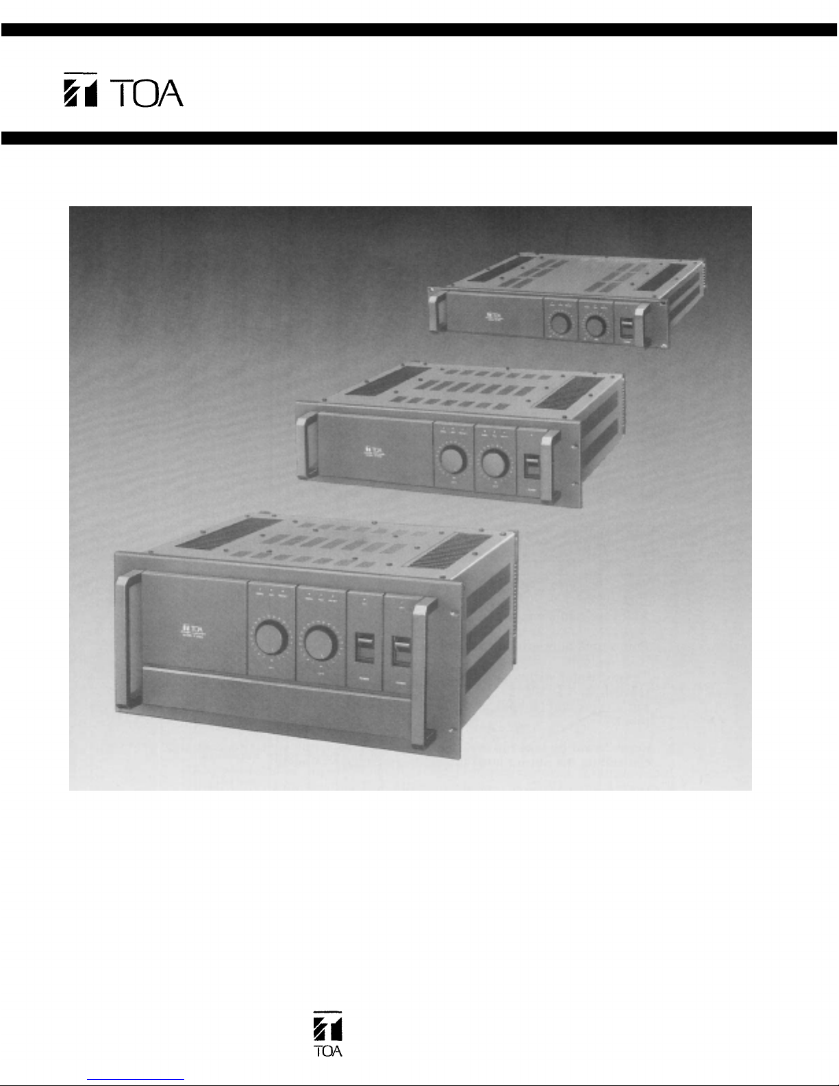
P-75D
P-300D
P-150D
TOA Corporation
KOBE, JAPAN
Page 2

Contents
Precautions
General
Features
Specifications
Performance
Front
Panel
Rear
Panel
Input/Output
..................................................... 1
Description
........................................
................................................
..........................................
Graphs
....................................
.............................................
..............................................
Connections
...............................
2~ 3
4~ 6
7~12
13~14
15~16
17~22
Installation Precautions .................................23~26
Appearance
................................................
2
27
Precautions
1. XLR type audio connectors are factory wired as follows.
Pins 1 and 2 are ground (shield); pin 3 is hot (high, plus).
The connector wiring changes with use of an optional matching transformer.
(Model No. PU-101T)
Pin 1 is ground (shield), Pin 2 is cold (low, minus), and pin 3 is hot (high,
plus).
2. Care should be taken in making connections, selecting signal sources and
controlling the output level to avoid any damage to loads.
3. Never parallel the two amplifier outputs together.
4. Do not operate the amplifier from power mains which exceeds the indicated
mains voltage by more than 10%.
5. Never connect the output of the amplifier to any other power source.
6. Do not expose the amplifier to corrosive chemicals or liquids such as, soft
drinks, salt water, etc.
7. Always refer the amplifier to qualified technical service personnel. There
are no user servicable parts inside.
- 1 -
Page 3

General Description
The P-75D, P-150D and P-300D are Toa professional 2-channel (stereo) power
amplifiers, with nominal power outputs of 75 watts, 150 watts and 300 watts,
respectively per channel with both channels driven into 8 ohms. Into 4 ohms they
deliver 100 watts, 220 watts and 480 watts. In BTL (Bridged) mono use, the P-
75D, P-150D and P-300D deliver 200 watts, 440 watts and 960 watts of power
into 8 ohms. All models have frequency response of +0dB, –0.5dB (20Hz to
20kHz), total harmonic distortion of less than 0.1% (at each nominal power
outputs, 8 ohms, 20Hz to 20kHz).
Each model offers many unique features such as, an octal socket for optional
matching transformer to convert unbalanced input to balanced, magnetic circuit
breaker, calibrated input attenuator, short circuit protection circuitry, 3-second
turn-on delay, current limiter circuitry, protection indicator LED's, signal
presence indicator LED's, peak indicator LED's, ground terminal strip, high pass
filter, mono/stereo mode switch, and true dual-mono configuration. Protection
indicator LED's are designed to actuate in cases of short circuit, D.C drift, turn-on
delay and thermal warning. The signal presence indicator LED's glow when
more than -30dB signal level is fed to the inputs.
For ease of maintenance and service, each channel of these amplifiers is built
with modular, plug-in boards on a sub-chassis that can be quickly removed and
replaced or repaired.
All models are mechanically reinforced by a rugged front panel made of 3mm
(1/8") thick cast-aluminum and lined with another 3mm (1/8") thick steel. With
their overall sturdy construction, they are capable of withstanding even the
roughest use on the road.
Features
1. Magnetic Circuit Breaker Power Switch
2. Calibrated Input Attenuators
3. Short-Circuit Protection Circuitry
4. 3-Second Turn-On Delay
Both the primary mains (A.C. line) overload protection and the on/off switch
are combined into a rocker-actuated, magnetic circuit breaker, whose
operation, unlike fuses, is predictable and independent of temperature.
Returning the switch to the "on" position resets the system.
22-step detented input attenuators are provided for easy, accurate input
sensitivity adjustment. The attenuators are in 2dB steps from 0dB
attenuation to -34dB, then steps of -37dB, -42dB, -50dB, infinity. This
arrangement provides a smooth, noise free transition from the highest to the
lowest audio level.
Speaker protection is provided with relay circuitry that disconnects the load
whenever a short-circuit or harmful D.C. current is present across the output
terminals.
To help eliminate annoying clicks or pops which can occur upon turn-on in
large sound systems, a three second mute/delay circuit is incorporated. The
mute/delay circuit actuates the relay, and then disconnects the speakers the
instant the circuit breaker is shut off.
- 2 -
Page 4

Features
5. Current Limiter Circuitry
6. Protection Indicator LED's (Including Thermal Warning)
7. Signal Presence Indicator LED's
8. Peak Indicator LED's
Protection against shorted and low impedance loads is provided with
dependable current limiting as well as protection against overloaded power
supplies and input overload.
The LED's illuminate when the protection relay is activated in the following
situations.
1) Short-circuit
2) D.C. drift
3) Turn-on delay
The LED's also flash when either of two heat sinks reaches more than 105°C
in temperature.
The LEDs glow when more than –30dB level signal is fed to the inputs
regardless of the input attenuator setting and output power level. They are
helpful to assure that sufficient input signal is fed to drive the amplifiers.
The LED's actuate by means of an input/output comparator, and glow when
the output signal is clipped.
9. Ground Terminal Strip
Provision for isolating chassis ground from signal ground is provided on the
rear panel.
10. High Pass Filter Switch
A switchable 15Hz high pass filter (12dB/octave) is provided to prevent
damage from subsonic frequencies.
11. Heavy aluminum Die-Cast Panel
The power amplifiers are constructed to withstand even the roughest use on
the road. Their aluminum die-cast front panels are mountable in standard
19-inch rack. A pair of sturdy carrying handles provide protection for the
front panel controls and easy handling.
12. Mono/Stereo Mode Switch
An external slide switch provides quick and easy conversion for
determining the power amplifiers' operating configuration as a single or dual
channel amplifier.
13. Two Regulated AC Supplies (applicable to P-300D)
The P-300D is designed in a true dual-mono configuration. There are two
completely separate amplifiers sharing only a common chassis and AC cord.
Even the circuit breaker AC switches are separate.
The P-150 a nd P-75D are designed in dual-mono configuration, but share one
power transformer and circuit breaker AC switch.
- 3 -
Page 5

Specifications (P-75D)
Power Output
75 watts minimum sine wave continuous average power
output per channel with both channel driving 8-ohm loads
over a power band from 20Hz to 20kHz. The maximum
Total Harmonic Distortion (THD) at any power level from
250 milliwatts to 75 watts shall be no more than 0.1%.
100 watts minimum sine wave continuous average power
output per channel with both channel driving 4-ohm loads
over a power band from 20Hz to 20kHz. The maximum
Total Harmonic Distortion (THD) at any power level from
250 milliwatts to 100 watts shall be no more than 0.15%.
80 watts continuous average sine wave power into 8 ohms
with less than 0.1% THD, at 1 kHz, both channels driven.
Frequency Response
+0dB, –0.5dB, 20Hz to 20kHz
Total Harmonic Distortion
Less th an 0.005% at 75 watts, 8-ohm, 1kHz
Less than 0.1% at 75 watts, 8-ohm, 20Hz to 20kHz
Intermodulation Distortion
0.05% using frequencies of 60Hz and 7kHz, mixed in a
ratio of 4:1, at power output of 25 watts into 8-ohm
Input Sensitivity
An input of +4dB (1.23V), ±0.5dB, produces an output of
75 w atts into 8-ohm, INPUT ATTENUTOR set for
maximum level
Input Impedance
10k-ohm (unbalanced)
Damping Factor
Greater than 150 at any frequency from 20Hz to 1kHz
Greater than 50 at any frequency from 20Hz to 20kHz
Impedance Actual Output
Less than 0.06 ohms at any frequency from 20Hz to 1kHz
Less than 0.15 ohms at any frequency from 20Hz to 20kHz
Hum and Noise
109dB below rated output (20Hz — 20kHz)
114dB below rated output (IHF-A weighted)
Rise Time
10 microseconds, or better (10% -90% of 1 volt at 1kHz
square wave output)
Slew Rate
10 volts per microsecond, or better (at 25 watts into 8-ohm,
200kHz square wave input)
Channel Separation
At least 95dB at 1kHz
At least 85dB at 20kHz
Phase Shift
20Hz to 20kHz, ±15 degrees
Offset Voltage
Less than ±10mV DC
Input Connectors (per channel)
One "male" and one "female" XLR connector in paralle, 2
"cold", pin 3 "hot", and pin 1 "shield". XLR's are
unbalanced and in parallel with two tip-sleeve (standard)
phone jack.
Accessory Socket
8-pin octal socket accepts an optional matching transformer module for balanced input, or user options (pins
include ±VCC, signal i nput/output and circuit ground)
Output Connectors (per channel)
Barrier Strip Terminal
Ground Terminal Strip
2 lug terminal block with removal shorting strap
Indicators
A pair of green LED's for signal presence
A pair of red LED's fo r output clipping
A pair of red LED's for circuit protection and thermal
warning
A green LED for power ON
Controls
Input Attenuators
22-position, log-linear, detented and dB-calibrated input
attenuators (one per channel) attenuates input signal in
2dB steps from 0dB attenuation to -34dB, the n steps of
-37dB, -42dB, -50dB, infinity.
Circuit Breaker AC Switch
High Pass Filter Switches (IN/OUT)
-12dB per octave at 15Hz
Accessory Switches (IN/OUT)
Bypass for octal socket
Mode Switch
Switchable for stereo/mono mode operation
Overall Protection
AC line is protected by circuit breaker.
Protection LED's flashes when heat sink temperature
reaches more than 105°C.
Protection LED's turn on when the protection relay
activates in such cases that DC currant is fed to output,
and that short-circuit occurs.
Turn On/Turn Off
No turn off transient. Three second delay turn On with
minimum thumps and no dagerous transients
AC Line Voltage
AC mains. 50Hz/60Hz
Power Consumption
400 watts maximum
Finish
Black painting
Dimensions (W×H×D)
483 × 89 × 475
19 × 3-1/2 × 18-3/4 (inches)
(mm)
Weight
13kg
(29
lbs)
MONAURAL MODE SPECIFICATIONS
(P-75D)
Power Output
150 watts minimum sine wave continuous average power
output monaural driving 16-ohm loads over a power band
from 20Hz to 20kHz. The maximum Total Harmonic
Distortion (THD) at any power level from 250 milliwatts
to 150 watts shall be no more than 0.1%.
200 watts minimum sine wave continuous average power
output monaural driving 8-ohm loads over a power band
from 20Hz to 20kHz. The maximum Total Harmonic
Distortion (THD) at any power level from 250 milliwatts
to 200 watts shall be no more than 0.15%.
210 watts continuous average sine wave power into 8-ohm
with less than 0.1% THD at 1kHz
Frequency Response
+0dB, –0.5dB, 20Hz to 20kHz
Total Harmonic Distortion
Less than 0.05% at 200 watts into 8-ohm at 1kHz
Intermodulation Distortion
0.05% using frequencies of 60Hz and 7kHz, mixed in a ratio
of 4:1, at p ow er output of 50 watts into 8-ohm
Damping Factor (at 16-ohm)
Greater than 100 at any frequency from 20Hz to 1kHz
Greater than 30 at any frequency from 20Hz to 20kHz
Impedance Actual Output
Less than 0.15-ohm at any frequency from 20Hz to 1kHz
Less than 0.3-ohm at any frequency from 20Hz to 20kHz
Hum and Noise
112dB below rated output (20Hz to 20kHz)
116dB be low rated output (IHG-A weighted)
Note: 0dB is referenced to 0.775 volts RMS.
- 4 -
Page 6

Specifications (P-150D)
Power Output
150 waits minimum sine wave continuous average power
output per channel with both channel driving 8-ohm loads
over a power band from 20Hz to 20kHz. The maximum
Total Harmonic Distortion (THD) at any power level from
250 milliwatts to 150 watts shall be no more than 0.1%.
220 watts minimum sine wave continuous average power
output per channel with both channel driving 4-ohm loads
over a power band from 20Hz to 20kHz. The maximum
Total Harmonic Distortion (THD) at any power level from
250 milliwatts to 220 watts shall be no more than 0.15%.
160 watts continuous average sine wave power into 8
ohms with less th an 0.1% THD, at 1 kHz, both channels
driven.
Frequency Response
+0dB, –0.5dB, 20Hz to 20kHz
Total Harmonic Distortion
Less th an 0.001% at 150 watts, 8-ohm, 1kHz
Less than 0.1% at 150 watts, 8-ohm, 20Hz to 20kHz
Intermodulation Distortion
0.05% using frequencies of 60Hz and 7kHz, mixed in a
ratio of 4:1, at power output of 50 watts into 8-ohm
Input Sensitivity
An input of +4dB (1.23V), ±0.5dB, produces an output of
150 watts into 8-ohm, INPUT ATTENUTOR set for
maximum level
Input Impedance
10k-ohm (unbalanced)
Damping Factor
Greater than 150 at any frequency from 20Hz to 1kHz
Greater than 70 at any frequency from 20Hz to 20kHz
Impedance Actual Output
Less than 0.06 ohms at any frequency from 20Hz to 1kHz
Less than 0.12 ohms at any frequency from 20Hz to 20kHz
Hum and Noise
110dB below rated output (20Hz — 20kHz) 115dB below
rated output (IHF-A weighted)
Rise Time
10 microseconds, or better (10% -90% of 1 volt at 1kHz
square wave output)
Slew Rate
10 volts per microsecond, or better (at 50 watts into 8-ohm,
200kHz square wave input)
Channel Separation
At least 95dB at 1kHz
At least 75dB at 20kHz
Phase Shift
20Hz to 20kHz, ±15 degrees
Offset Voltage
Less than ±10mV DC
Input Connectors (per channel)
One "male" and one "female" XLR connector in paralle, 2
"cold", pin 3 "hot", and pin 1 "shield". XLR's are
unbalanced and in parallel with two tip-sleeve (standard)
phone jack.
Accessory Socket
8-pin octal socket accepts an optional matching transformer module for balanced input, or user options (pins
include ±VCC, signal input/output and circuit ground)
Output Connectors (per channel)
Barrier Strip Terminal
Ground Terminal Strip
2 lug terminal block with removal shorting strap
Indicators
A pair of green LED's for signal presence
A pair of red LED's for output clipping
A pair of red LED's for circuit protection and thermal
warning
A green LED for power ON
Controls
Input Attenuators 22-position, log-linear, detented and
dB-calibrated input attenuators (one per channel)
attenuates input signal in 2dB steps from 0dB attenuation
to -34dB, then steps of -37dB, -42dB, -50dB, infinity.
Circuit Breaker AC Switch
High Pass Filter Switches (IN/OUT)
-12dB pe r octave at 15Hz
Accessory Switches (IN/OUT)
Bypass for octal socket
Mode Switch
Switchable for stereo/mono mode operation
Overall Protection
AC line is protected by circuit breaker.
Protection LED's flashes when heat sink t emperature
reaches more than 105°C.
Protection LED's turn on when the protection relay
activates in such cases that DC currant is fed to output,
and that short-circuit occures.
Turn On/Turn Off
No turn off transient. Three second delay turn On with
minimum thumps and no dagerous transients
AC Line Voltage
AC mains. 50Hz/60Hz Dimensions (W×H×D)
Power Consumption 483 × 133 × 475 (mm)
800 watts maximum 19 × 5-1/4 × 18-3/4 (inches)
Finish Weight
Black painting 20kg (44 lbs)
MONAURAL MODE SPECIFICATIONS
(P-150D)
Power Output
300 watts minimum sine wave continuous average power
output monaural driving 16-ohm loads over a power band
from 20Hz to 20kHz. The maximum Total Harmonic
Distortion (THD) at any power level from 250 milliwatts
to 300 watts shall be no more than 0.1%.
440 watts minimum sine wave continuous average power
output monaural driving 8-ohm loads over a power band
from 20Hz to 20kHz. The maximum Total Harmonic
Distortion (THD) at any power level from 250 milliwatts
to 440 watts shall be no more than 0.15%.
500 watts continuous average sine wave power into 8-ohm
with less than 0.1% THD at 1kHz
Frequency Response
+0dB, –0.5dB, 20Hz to 20kHz
Total Harmonic Distortion
Less t han 0.01% at 440 watts into 8-ohm at 1kHz
Intermodulation Distortion
0.05% using frequencies of 60Hz and 7kHz, mixed in a ratio
of 4:1, at power output of 100 watts into 8-ohm
Damping Factor (at 16-ohm)
Greater than 100 at any frequency from 20Hz to 1kHz
Greater than 70 at any frequency from 20Hz to 20kHz
Impedance Actual Output
Less th an 0.16-ohm at any frequency from 20Hz to 1kHz
Less than 0.2-ohm at any frequency from 20Hz to 20kHz
Hum and Noise
110dB below rated output (20Hz to 20kHz)
115dB below rated output (IHG-A weighted)
Note: 0dB is referenced to 0.775 volts RMS.
- 5 -
Page 7

Specifications (P-300D)
Power Output
300 watts minimum sine wave continuous average power
output per channel with both channel driving 8-ohm loads
over a power band from 20Hz to 20kHz. The maximum
Total Harmonic Distortion (THD) at any power level from
250 milliwatts to 300 watts shall be no more than 0.1%.
480 watts minimum sine wave continuous average power
output per channel with both channel driving 4-ohm loads
over a power band from 20Hz to 20kHz. The maximum
Total Harmonic Distortion (THD) at any power level from
250 milliwatts to 480 watts shall be no more than 0.15%.
320 watts continuous average sine wave power into 8
ohms with less than 0.1% THD, at 1 kHz, both channels
driven.
Frequency Response
+0dB, –0.5dB, 20Hz to 20kHz
Total Harmonic Distortion
Less than 0.01% at 300 watts, 8-ohm, 1kHz
Less than 0.1% at 300 watts, 8-ohm, 20Hz to 20kHz
Intermodulation Distortion
0.05% using frequencies of 60Hz and 7kHz, mixed in a
ratio of 4:1, at power output of 100 watts into 8-ohm
Input Sensitivity
An input of +4dB (1.23V), ±0.5dB, produces an output of
300 watts into 8-ohm, INPUT ATTENUTOR set for
maximum level
Input Impedance
10k-ohm (unbalanced)
Damping Factor
Greater than 260 at any frequency from 20Hz to 1kHz
Greater than 95 at any frequency from 20Hz to 20kHz
Impedance Actual Output
Less tha n 0.03 ohms at any frequency from 20Hz to 1kHz
Less than 0.08 ohms at any frequency from 20Hz to 20kHz
Hum and Noise
109dB below rated output (20Hz — 20kHz)
114dB below rated output (IHF-A weighted)
Rise Time
10 microseconds, or better (10% -90% of 1 volt at 1kHz
square wave output)
Slew Rate
10 volts per microsecond, or better (at 100 watts into 8-
ohm, 200kHz square wave input)
Channel Separation
At least 90dB at 1kHz
At least 75dB at 20kHz
Phase Shift
20Hz to 20kHz, ±15 degrees
Offset Voltage
Less than ±10mV DC
Input Connectors (per channel)
One "male" and one "female" XLR connector in paralle, 2
"cold", pin 3 "hot", and pin 1 "shield". XLR's are
unbalanced and in parallel with two tip-sleeve (standard)
phone jack.
Accessory Socket
8-pin octal socket accepts an optional matching transformer module for balanced input, or user options (pins
include ±VCC, signal input/output and circuit ground)
Output Connectors (per channel)
Standard 3/4-inch spacing, "5-way" binding posts
Ground Terminal Strip
2 lug terminal block with removal shorting strap
Indicators
A pair of green LED's for signal presence
A pair of red LED's for outpu t clipping
A pair of red LED's for circuit protection and thermal
warning
A green LED for power ON
Controls
Input Attenuators
22-position, log-linear, detented and dB-calibrated input
attenuators (one per channel) attenuates input signal in
2dB steps from 0dB attenuation to -34dB, then steps of
-37dB, -42dB, -50dB, infinity.
Circuit Breaker AC Switch
High Pass Filter Switches (IN/OUT)
-12dB p er octave at 15Hz
Accessory Switches (IN/OUT)
Bypass for octal socket
Mode Switch
Switchable for stereo/mono mode operation
Overall Protection
AC line is protected by circuit breaker.
Protection LED's flashes when heat sink temperature
reaches more than 105°C.
Protection LED's t urn on when the protection relay
activates in such cases that DC currant is fed to output,
and that short-circuit occurs.
Turn On/Turn Off
No turn off transient. Three second delay turn On with
minimum thumps and no dagerous transients
AC Line Voltage
AC mains. 50Hz/60Hz Dimensions (W ×H ×D)
Power Consumption 483 × 222 × 475 (mm)
1.7k watts maximum 19 × 8-3/4 × 18-3/4 (inches)
Finish Weight
Black painting 35kg (77 lbs)
MONAURAL MODE SPECIFICATIONS
(P-300D)
Power Output
600 watts minimum sine wave continuous average power
output monaural driving 16-ohm loads ove r a power band
from 20Hz to 20kHz. The maximum Total Harmonic
Distortion (THD) at any power level from 250 milliwatts
to 600 watts shall be no more than 0.1%.
960 watts minimum sine wave continuous average power
output monaural driving 8-ohm loads over a power band
from 20Hz to 20kHz. The maximum Total Harmonic
Distortion (THD) at any power level from 250 milliwatts
to 960 watts shall be no more than 0.15%.
1100 watts continuous average sine wave power into 8-
ohm with less t ha n 0.1% THD a t 1kH z
Frequency Response
+0dB, –0.5dB, 20Hz to 20kHz
Total Harmonic Distortion
Less than 0.005% at 960 watts into 8-ohm at 1kHz
Intermodulation Distortion
0.05% using frequencies of 60Hz and 7kHz, mixed in a ratio
of 4:1, at power output of 200 watts into 8-ohm
Damping Factor (at 16-ohm)
Greater than 160 at any frequency from 20Hz to 1kHz
Greater than 50 at any frequency from 20Hz to 20kHz
Impedance Actual Output
Less than 0.1-ohm at any frequency from 20Hz to 1kHz
Less tha n 0.3-ohm at any frequency from 20Hz to 20kHz
Hum and Noise
109dB below rated output (20Hz to 20kHz)
114dB below rated output (IHG-A weighted)
Note: 0dB is referenced to 0.775 volts RMS.
– 6 –
Page 8
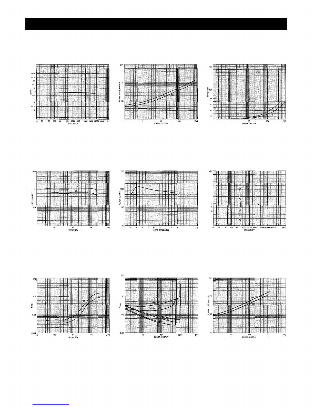
Performance Graphs (P-75D)
POWER BANDWIDTH
(BOTH CHANNELS DRIVEN)
T.H.D. vs FREQUENCY
(BOTH CHANNEL DRIVEN)
LOAD IMPEDANCE vs POWER OUTPUT
T.H.D. vs POWER OUTPUT
(BOTH CHANNELS DRIVEN)
FREQUENCY RESPONSE
(BOTH CHANNEL DRIVEN)
INTERMODULATION DISTORTION
VS POWER OUTPUT (ONE CHANNEL DRIVEN)
MEASURED WITH A 4 : 1 MIX AT 60 Hz and 7 kHz
DAMPING FACTOR vs FREQUENCY
AT 8 LOAD IMPEDANCE
ACTUAL OUTPUT IMPEDANCE
vs FREQUENCY
– 7 –
CROSSTALK
(BOTH INPUT ATTENUATORS
AT MAXIMUM LEVEL)
Page 9
Performance Graphs (P-75D)
PHASE RESPONSE
POWER BANDWIDTH (MONO MODE)
POWER CONSUMPTION
(BOTH CHANNEL DRIVEN)
LOAD IMPEDANCE vs POWER OUTPUT
(MONO MODE)
POWER EFFICIENCY
(BOTH CHANNEL DRIVEN)
FREQUENCY RESPONSE (MONO MODE)
T.H.D. vs FREQUENCY (MONO MODE)
T.H.D. vs POWER OUTPUT
(MONO MODE)
- 8 -
POWER CONSUMPTION
(MONO MODE)
Page 10

Performance Graphs (P-150D)
POWER BANDWIDTH
(BOTH CHANNEL DRIVEN)
T.H.D. vs FREQUENCY
(BOTH CHANNEL DRIVEN)
LOAD IMPEDANCE vs POWER OUTPUT
T.H.D. vs POWER OUTPUT
(BOTH CHANNELS DRIVEN)
FREQUENCY RESPONSE
(BOTH CHANNEL DRIVEN)
INTERMODULATION DISTORTION
VS POWER OUTPUT (ONE CHANNEL DRIVEN)
MEASURED WITH A 4 : 1 MIX AT 60 Hz and 7 kHz
DAMPING FACTOR vs FREQUENCY
AT 8 LOAD IMPEDANCE
ACTUAL OUTPUT IMPEDANCE
vs FREQUENCY
- 9 -
CROSSTALK
(BOTH INPUT ATTENUATORS
AT MAXIMUM LEVEL)
Page 11

Performance Graphs (P-150D)
PHASE RESPONSE
POWER BANDWIDTH (MONO MODE)
POWER CONSUMPTION
(BOTH CHANNEL DRIVEN)
LOAD IMPEDANCE vs POWER OUTPUT
(MONO MODE)
POWER EFFICIENCY
(BOTH CHANNEL DRIVEN)
FREQUENCY RESPONSE (MONO MODE)
T.H.D. vs FREQUENCY (MONO MODE)
T.H.D. vs POWER OUTPUT
(MONO MODE)
- 10 -
POWER CONSUMPTION
(MONO MODE)
Page 12
Performance Graphs (P-300D)
POWER BANDWIDTH
(BOTH CHANNEL DRIVEN)
T.H.D. vs FREQUENCY
(BOTH CHANNEL DRIVEN)
LOAD IMPEDANCE vs POWER OUTPUT
T.H.D. vs POWER OUTPUT
(BOTH CHANNELS DRIVEN)
FREQUENCY RESPONSE
(BOTH CHANNEL DRIVEN)
INTERMODULATION DISTORTION
VS POWER OUTPUT (ONE CHANNEL DRIVEN)
MEASURED WITH A 4 : 1 MIX AT 60 Hz and 7 kHz
DAMPING FACTOR vs FREQUENCY
ACTUAL OUTPUT IMPEDANCE
vs FREQUENCY
- 11 -
CROSSTALK
(BOTH INPUT ATTENUATORS
AT MAXIMUM LEVEL)
Page 13
Performance Graphs (P-300D)
PHASE RESPONSE
POWER BANDWIDTH (MONO MODE)
POWER CONSUMPTION
(BOTH CHANNEL DRIVEN)
LOAD IMPEDANCE vs OUTPUT POWER
(MONO MODE)
POWER EFFICIENCY
(BOTH CHANNEL DRIVEN)
FREQUENCY RESPONSE (MONO MODE)
T.H.D. vs FREQUENCY (MONO MODE)
T.H.D. vs OUTPUT POWER
(MONO MODE)
- 12 -
POWER CONSUMPTION
(MONO MODE)
Page 14

Front Panel
P-75D
P-150D
- 13 -
Page 15

Front Panel
P-300D
Input Attenuators
Calibrated in dB, detented input attenuators decrease input signal levels before the amplifier stage.
Power Indicator LED
The green LED glows when the power switch is "on".
Signal Presence Indicator LED's
The LED's glow when more than —30dB level signal is fed to the inputs regardless of the input attenuator
setting and output power level.
Peak Indicator LED's
The peak indicator LED will glow when the amplifier reaches just below clipping. It is quite common for
the LED to flash on and off during high level operation. However, if the LED remains steadily lighted, the
input attenuator level should be lowered until the LED only flashes at the highest peaks.
Protection Indicator LED's
These LED's remain lit for 3 seconds after the power switch has been turned on. They also come on when
the protection circuit is activated, and flash when the temperature of the heat sinks exceeds 105°C. See
Table "Fault Protection" on page 26.
Circuit Breaker Power Switch
This switch is a combination circuit breaker and a power mains ON/OFF switch. If the circuit breaker
trips, it may be reset by first setting to the "OFF" position and then returning to the "POWER ON"
position, always check the amplifier and associated wiring before resetting the circuit breaker.
- 14 -
Page 16
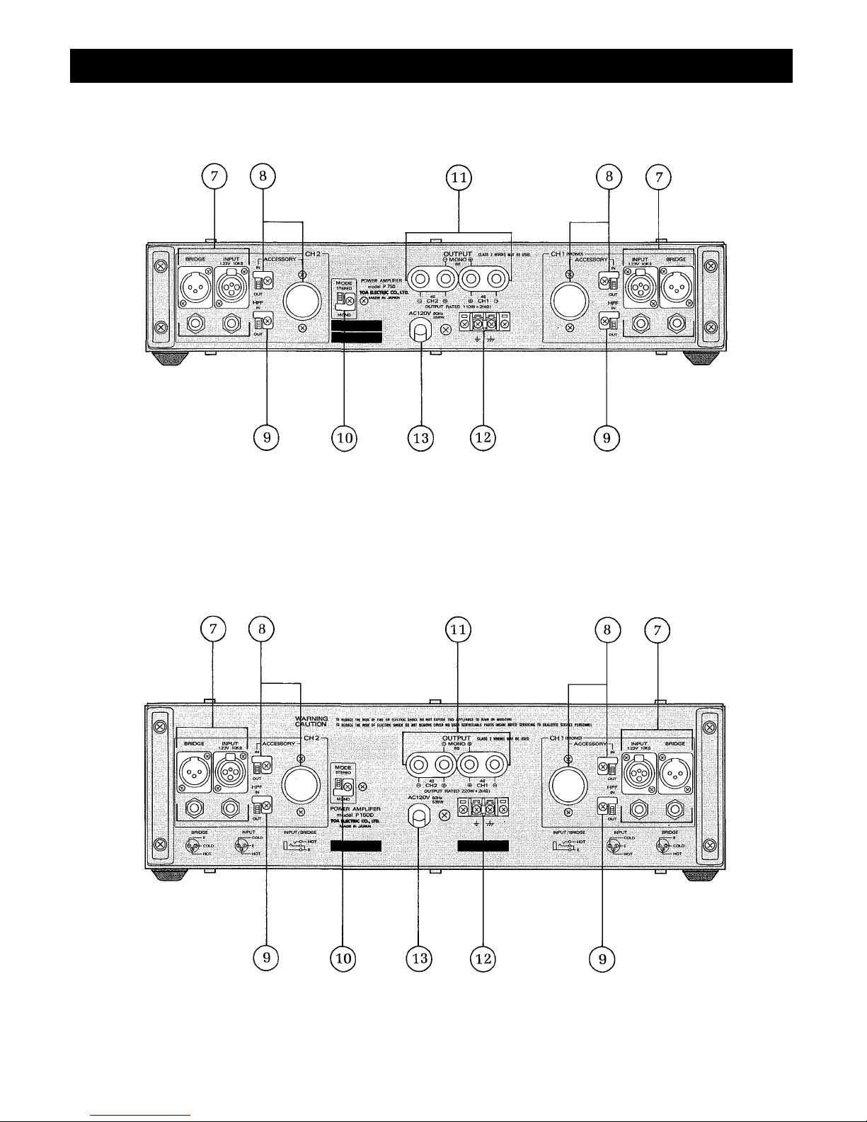
Rear Panel
P-75D
P-150D
- 15 -
Page 17

Rear Panel
P-300D
Input connectors
The two XLR input connectors on each channel are unbalanced and are wired in parallel with each other
and with the two phone jacks that can accept tip/sleeve as well as a tip/ring/sleeve type of plug.
Accessory
To convert the XLR input connectors to balanced operation, remove the octal socket cover and insert the
matching transformer (PU-101T). Then loosen the screw and set the In/Out switch to "In" after removing
the L shaped metal fitting. You can prevent accidental change in switch position by attaching the metal
fitting to the OUT side. The same metal fitting is used in the High Pass Filter Switch and Mode Switch on
each channel to secure the desired switch position.
High Pass Filter Switch
A switchable 15Hz high pass filter (12dB/octave) prevents damage from subsonic frequencies.
Mono/Stereo Mode Switch
Place this switch in the STEREO position for dual amplifier use, and in the MONO position for single
amplifier use.
Output Connectors
Standard 5-way binding posts (3/4" spacing) accept banana plugs or direct wired connections. For mono
use, two red binding posts are used with the mode switch in the MONO position.
Ground Terminal Strip
Remove the strap to isolate chassis ground from signal ground. This may help prevent ground loop hums
caused by multiple ground paths.
AC Power Cord.
- 16 -
Page 18

Input/Output Connections
P-75D Typical Stereo Hookup
All XLR type connectors are unbalanced
connection. The pin 1 and 2 ground (shield)
the pin 3 hot (high, plus).
UNBALANCED SIGNAL
FROM MIXER,
PREAMPLIFIER, ETC.
All Phone jacks are unbalanced connection.
UNBALANCED SIGNAL
FROM MIXER,
PREAMPLIFIER, ETC.
BALANCED SIGNAL
FROM MIXER,
PREAMPLIFIER, ETC.
OPTIONAL INPUT TRANSFOMER
model PU-101T
The pin 1 ground (shield), the pin 2 cold (Low, minus),
the pin 3 hot (high, plus).
– 17 –
Page 19

Input/Output Connections
P-75D Typical Mono Hookup
UNBALANCED SIGNAL
FROM MIXER,
PREAMPLIFIER, ETC.
UNBALANCED SIGNAL
FROM MIXER,
PREAMPLIFIER, ETC.
OPTIONAL INPUT TRANSFOMER
BALANCED SIGNAL
FROM MIXER,
PREAMPLIFIER, ETC.
For balanced connection, all devices involved need to be of balanced type. When extending the
amplifier using the bridge terminal of the P-75D, insert the PU-101T matching transformer into the
octal socket marked "ACCESSORY", and set the ACCESSORY IN/OUT switch to IN.
model PU-101T
- 18 -
Page 20

Input/Output Connections
P-150D Typical Stereo Hookup
All XLR type connectors are unbalanced connec-
tion.
The pin 1 and 2 ground (shield), the pin
3 hot (high, plus).
UNBALANCED SIGNAL
FROM MIXER,
PREAMPLIFIER, ETC.
All Phone jacks are unbalanced connection.
UNBALANCED SIGNAL
FROM MIXER,
PREAMPLIFIER, ETC.
BALANCED SIGNAL
FROM MIXER,
PREAMPLIFIER, ETC.
OPTIONAL INPUT TRANSFORMER
model PU-101T
The pin 1 ground (shield), the pin 2 cold (low, minus),
the pin 3 hot (high, plus).
- 19 -
Page 21

Input/Output Connections
P-150D Typical Mono Hookup
UNBALANCED SIGNAL
FROM MIXER,
PREAMPLIFIER, ETC.
UNBALANCED SIGNAL
FROM MIXER,
PREAMPLIFIER, ETC.
BALANCED SIGNAL
FROM MIXER,
PREAMPLIFIER, ETC.
For balanced connection, all devices involved need to be of balanced type. When extending the
amplifier using the bridge terminal of the P-75D, insert the PU-101T matching transformer into the
octal socket marked "ACCESSORY", and set the ACCESSORY IN/OUT switch to IN.
OPTIONAL INPUT TRANSFORMER
model PU-101T
- 20 -
Page 22

Input/Output Connections
P-300D Typical Stereo Hookup
All XLR type connectors are unbalanced
connection.
The pin 1 and 2 ground (shield),
the pin 3 hot (high, plus).
UNBALANCED SIGNAL
FROM MIXER,
PREAMPLIFIER, ETC.
UNBALANCED SIGNAL
FROM MIXER,
PREAMPLIFIER, ETC.
BALANCED SIGNAL
FROM MIXER,
PREAMPLIFIER, ETC.
The pin 1 ground (shield),
the pin 2 cold (low, minus),
the pin 3 hot (high, plus).
OPTIONAL INPUT TRANSFORMER
model PU-101T
- 21 -
Page 23

Input/Output Connections
P-300D Typical Mono Hookup
UNBALANCED SIGNAL
FROM MIXER,
PREAMPLIFIER, ETC.
UNBALANCED SIGNAL
FROM MIXER,
PREAMPLIFIER, ETC.
BALANCED SIGNAL
FROM MIXER,
PREAMPLIFIER, ETC.
For balanced connection, all devices involved need to be of balanced type. When extending the
amplifier using the bridge terminal of the P-75D, insert the PU-101T matching transformer into the
octal socket marked "ACCESSORY", and set the ACCESSORY IN/OUT switch to IN.
OPTIONAL INPUT
TRANSFORMER
model PU-101T
The pin 1 ground (shield),
the pin 2 cold (low, minus),
the pin 3 hot (high, plus).
- 22 -
Page 24

Installation Precaution
Input and output cables
In view of high power output produced, separate the input cable fr om the output cable when
installing the P-75D, P-150D or P-300D. If they are in close proximity to each other, oscillation may
occur. Particular care should be given to the wiring when mounting unit in a rack cabinet.
Ground Loops
In any audio system, there are numerous ways by which ground loops can be created. For example,
they may occur when the P-75D, P-150D and P-300D are mounted in a rack cabinet, or through AC
ground when the amps are connected with preamps and mixers. These ground loops may cause hum
and noise if care is not taken during connection. An increase in noise from ground loops may be
minimized by breaking the ground loop. Generally, the chassis ground of the signal line should be
broken as shown below.
Main AC Ground
When a Y cord is used, shorten the wiring to minimize noise.
A ground lift terminal is provided on the rear of the P-75D, P-150D and P-300D. Removing the bar in
the terminals lifts ground.
Since the P-75D, P-150D an d P-300D are high power amplifiers, be careful with ventilation when
they are installed. Do not block vents on the top pane. See sketch.
P-75D, P-150D, P-300D
- 23 -
Page 25

Installation Precaution
Mounting in an enclosed rack cabinet
The P-75D, P-150D and P-300D are mountable in a standard 19" rack. When mounting, insert a 1-
unit-sized perforated panel between the units mounted, and place the same at the bottom of the rack.
Be sure to mount a perforated panel larger than 1 unit size at the top of the rack. This is required to
allow adequate heat ventilation. See illustration.
P-75D or
P-150D or
P-300D
P-75D or
P-150D o r
P-300D
P-75D or
P-150D or
P-300D
On the road use.
The P-75D, P-150D and P-300D are sturdily constructed with an aluminum die-cast front panel that
is reinforced by means of an iron plate attached to its back. To ensure that strength is maintained
during their transportation from one place to another, however, you should also reinforce each unit
from the back of the rack with a special support bracket. This can be accomplished by removing
cord-hangers on the rear panel, and screws t hat hold the rear panel to chassis, and fitting the special
support brackets through the holes.
Top view
Side view
Special support bracket
- 24 -
Page 26

Installation Precaution
Mono Operation
The P-75D, P-150D and P-300D are designed to be used as mono amplifiers by placing their mode
switches in mono positions. In the mono mode total speaker impedance should not be lower than 8
ohms.
Source Resistance and Damping Factor vs. Length and Size of Output
Leads
The following figure indicates that a 100 foot length of # 14 AWG annealed copper wire (two
conductor) yields a combined amplifier/cable source impedance of 0.5 ohms. A typical 8 ohms load
impedance is indicated, and this results in an effective damping factor of 15. (This damping factor is
less than the rated one of each model obtained with zero ohms cable resistance). Larger diameter
(lower wire gauge number) should be used for longer cable.
- 25 -
Page 27

Installation Precaution
Load Protection Methods
The most common of all load protection methods
is a fuse in series with the load. The fuse may be
single, fusing the overall system, or (in the case of
multi-element speaker systems), may be multiple
with one fuse for each speaker. Fuses help prevent
damage due to prolonged overload, but provide
essentially no protection against damage that may
be done by large transients. To minimize the
problem, high speed instrumentation fuses are
recommended. For a nomograph showing fuse size
vs. loudspeaker ratings, refer to the adjacent
figure.
Fault
Excessive current due
to overloads.
Short circuits (less than
0.4-ohm).
Temperature rise of
heatsink (more than
105°C).
DC drift.
Protection
Current limiter activates
at less 2 ohms in a stereo
mode, 4 ohms in a mono
mode.
Current limiter activates
and output relay is cut.
Output relay is cut.
Fault Protection Table
Indication
Peak LED illuminates.
Protection LED
illuminates.
Protection LED flashes.
Amp protection LED
illuminates.
Remove excessive loads.
Minimum speaker loads
are 4 ohms in stereo
mode, and 8 ohms in
mono mode.
Check speaker lines/
systems for shorts.
Check for adequate
ventilation.
Refer to qualified
service personnel.
Action
Restoration
Automatic restoration
after normal loads are
obtained.
Turn off power switch.
Turn on into operational
loads.
Automatic restoration
after temperature lowers
(to 75° - 95°C).
Automatic restoration
after normal bias is
regained.
- 26 -
Page 28

Appearance
P-75D
P-150D
P-300D
–27–
Page 29

TOA Corporation
KOBE, JAP AN
Printed in Japan
133-02-654-0A
 Loading...