

Page 1
OPERATING INSTRUCTIONS
PA AMPLIFIERS
P-2240 L
P-2240 H
P-2240 SA
Please follow the instructions in this manual to obtain the optimum results from this unit.
We also recommend that you keep this manual handy for future reference.
TOA Corporation
Page 2

TABLE OF CONTENTS
1. IMPORTANT SAFETY INSTRUCTIONS……………………….……….. 3
2. SAFETY PRECAUTIONS ………………………………………………… 3
3. GENERAL DESCRIPTION ……………………………………….………. 5
4. FEATURES…………………………………………………………………. 5
5. NOMENCLANTURE AND FUNCTIONS
5.1 Front …………………………………….………………..……………. 5
5.2 Rear ……………………………………………….………..………….. 5
6. CONNECTIONS
6.1. Input Connections ……………….………………………….….……. 6
6.2. Output Connections ………………………………….………..…….. 8
6.3. Example of External Equipment Connections …..….………..…… 8
7. INSTALLATION ……………………………………………..……....……... 9
8. VOLUME CONTROL SETTINGS ………………………………….…….. 9
9. BLOCK LEVEL DIAGRAM ……………………………………….…..…... 9
10. DIMENSIONAL DIAGRAM ………………………………….…....………. 10
11. SPECIFICATIONS …………………………………………….….....…….. 11
2
Page 3
1. IMPORTANT SAFETY
2. SAFETY PRECAUTIONS
INSTRUCTIONS
• Read these instructions.
• Keep these instructions.
• Heed all warnings.
• Follow all instructions.
• Do not use this apparatus near water.
• Clean only with dry cloth.
• Do not block any ventilation openings. Install in
accordance with the manufacture's instructions.
• Do not install near any heat sources such as
radiators, heat registers, stoves, or other apparatus
(including amplifiers) that produce heat.
• Do not defeat the safety purpose of the polarized
or grounding-type plug. A polarized plug has two
blades with one wider than the other. A grounding
type plug has two blades and a third grounding
prong. The wide blade or the third prongs are
provided for your safety. If the provided plug does
not fit into your outlet, consult an electrician for
replacement of the obsolete outlet.
• Protect the power cord from being walked on or
pinched particularly at plugs, convenience
receptacles, and the point where they exit from the
apparatus.
• Before installation or use, be sure to carefully read all
the instructions in this section for correct and safe
operation.
• Be sure to follow all the precautionary instructions in
this section, which contain important warnings and/or
cautions regarding safety.
• After reading, keep this manual handy for future
reference.
Safety Symbol and Message Conventions
Safety symbols and messages described below are used
in this manual to prevent bodily injury and property
damage which could result from mishandling.
Before operating your product, read this manual first and
understand the safety symbols and messages so you are
thoroughly aware of the potential safety hazards.
The exclamation point within an equilateral
triangle is intended to alert the user to the
presence of important operation and
maintenance (servicing) instruction in the
literature accompanying the appliance.
WARNING
Indicates a potentially hazardous situation which,
if mishandled, could result in death or serious
personal injury.
When Installing the Unit
• Only use attachments/accessories specified by the
manufacturer.
• Use only with the cart, stand,
tripod, bracket, or table
specified by the
manufacturer, or sold with the
apparatus.
• When a earth is used, use
caution when moving the
cart/apparatus combination to
avoid injury from tip-over.
• Unplug this apparatus during lightning storms or
when unused for long periods of time.
• Refer all servicing to qualified service personnel.
Servicing is required when the apparatus has been
damaged in any way, such as power-supply cord
or plug is damaged, Liquid has been spilled or
objects have fallen into the apparatus, the
apparatus has been exposed to rain or moisture,
does not operate normally, or has been dropped.
• WARNING: Do not expose the unit to rain or an
environment where it may be splashed by water or
other liquids, as doing so may result in fire or electric
shock.
• Use the unit only with the voltage specified on the unit.
Using a voltage higher than that which is specified may
result in fire or electric shock.
• Do not cut, kink, otherwise damage nor modify the
power supply cord. In addition, avoid using the power
cord in close proximity to heaters, and never place
heavy objects -- including the unit itself -- on the power
cord, as doing so may result in fire or electric shock.
• Avoid installing or mounting the unit in unstable
locations, such as on a rickety table or a slanted
surface. Doing so may result in the unit falling down
and causing personal injury and/or property damage.
• The terminals marked with the symbol are
hazardous live. The external wiring to these terminals
requires installation by an instructed person.
• The apparatus shall be connected to a mains socket
outlet with a protective earthling connection.
3
Page 4
When the Unit is in Use
• Should the following irregularity be found during use,
immediately switch off the power, disconnect the
power supply plug from the AC outlet and contact
your nearest TOA dealer. Make no further attempt to
operate the unit in this condition as this may cause
fire or electric shock.
• If you detect smoke or a strange smell coming from
the unit.
• If water or any metallic object gets into the unit.
• If the unit falls, or the unit ease breaks.
• If the power supply cord is damaged (exposure of
the core, disconnection, etc.)
• If it is malfunctioning (no tone sounds.)
• To prevent a fire or electric shock, never open nor
remove the unit case as there are high voltage
components inside the unit. Refer all servicing to you
nearest TOA dealer.
• Do not place cups, bowls, or other containers of
liquid or metallic objects on top of the unit. If they
accidentally spill into the unit, this may cause a fire or
electric shock.
Indicates a potentially hazardous situation which,
if mishandled, could result in moderate or minor
personal injury, and/or property damage.
When Installing the Unit
• Never plug in nor remove the power supply plug with
wet hands, as doing so may cause electric shock.
• When unplugging the power supply cord, be sure to
grasp the power supply plug; never pull on the cord
itself. Operating the unit with a damaged power
supply cord may cause a fire or electric shock.
• Do not block the ventilation slots in the unit's cover.
Doing so may cause heat to build up inside the unit
and result in fire.
• Avoid installing the unit in humid or dusty locations, in
locations exposed to the direct sunlight, near the
heaters, or in locations generating sooty smoke or
steam as doing otherwise may result in fire or electric
shock.
• To avoid electric shocks, be sure to unplug the unit's
power supply cord when connecting speakers.
• Be sure to follow the instructions below when rackmounting the unit. Failure to do so may cause a fire
or personal injury.
CAUTION
• Install the equipment rack on a stable, hard floor. Fix
it with anchor bolts or take other arrangements to
prevent it from falling down.
• When connecting the unit's power cord to an AC
outlet, use the AC outlet with current capacity
allowable to the unit.
• No rack-mounting screws are supplied with the unit.
Separately prepare the appropriate screws for the
rack.
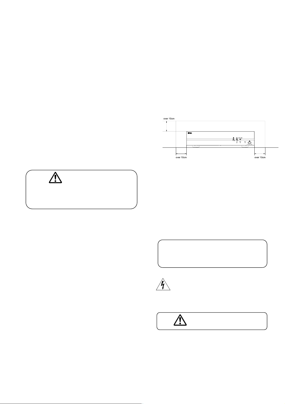
• Keep the 2000 series amplifiers over 10 cm away
from objects that may obstruct air flow to prevent the
unit's internal temperature rise.
When the Unit is in Use
• Do not operate the unit for an extended period of
time with the sound distorting. This is an indication of
a malfunction, which in turn can cause heat to
generate and result in a fire.
• Switch off the power, and unplug the power supply
plug from the AC outlet for safety purposes when
cleaning or leaving the unit unused for 10 days or
more. Doing otherwise may cause a fire or electric
shock.
An all-pole mains switch with a contact
separation of at least 3 mm in each pole shall be
incorporated in the electrical installation of the
building.
The lighting flash with arrowhead symbol,
within an equilateral triangle, is intended to
alert the user to the presence of uninsulated
''dangerous voltage'' within the product's
enclosure that may be of sufficient magnitude
to constitute a risk of electric shock to persons.
L'appareil ne doit pas être exposé aux éclaboussures
ou écoulements et tous objets remplis de liquide, tels
que vases, ne doivent pas être sur I'appareil.
ATTENTION
4
Page 5

3. GENERAL DESCRIPTION
TOA's Basic Power Amplifiers P-2240 is high cost-performance power amplifiers suited for broadcasting
paging or background music in schools, offices, shops, factories, mosques, churches and large rooms.
4. FEATURES
• High durability, high reliability, and high cost performance.
• Two balanced parallel inputs, one speaker line input.
• Speaker output of constant voltage distribution system (70V or 100V) and low impedance (4Ω).
• Operates on both AC and DC power.
• Semi fixed master volume control and independent speaker line input volume control.
• Semi fixed and independent tone controls of boost and cut type for both high and low frequencies.
• Power remote switch by make contact input.
5. NOMENCLATURES AND FUNCTIONS
5.1. Front
5.2. Rear
5
Page 6

1. Power Switch
Press to turn ON the power.
Press again to turn the power OFF.
Unplug AC Power Cord or disconnect DC Terminal to
get complete OFF the power.
2. Power Indicator
Lights green when power is switched ON.
3. Signal Indicator
Lights green when power is switched ON, and
indicates an output signal.
4. Peak Indicator
Lights red to indicate the output signal reaches the
peak level, this indicates that sound is distorted. In
such a case, adjust the master volume control to
reduce output level.
5. Master Volume Control
Adjusts the overall signal level.
6. Treble Control
Adjusts treble response. Rotate clockwise to increase
treble output, and counterclockwise to reduce it. The
center position provides flat characteristics.
10. DC Terminal
Connects to a DC power supply of 24V.
11. Output Terminals
Connect to speakers. When connecting speakers, use
only one of the speaker output terminals, low or high
impedance.
12. Terminal Cover
To avoid electric shocks by high voltage from
output/input terminal, put back the terminal cover after
connecting cords.
13. Speaker Line Input
40dB, 10kΩ, unbalanced. Connects to 100V line
speaker output.
14. Speaker Line In Volume Control
Adjusts the signal level.
15. Line Input
0dB, 10kΩ, transformer balanced. Connects to Line
Out/Rec Out of Mixer Amplifier or Loop Out of other
P-2240 Power Amplifier.
7. Bass Control
Adjusts bass response. Rotate clockwise to increase
bass output, and counterclockwise to reduce it. The
center position provides flat characteristics.
8. AC Power Cord
Connects to an AC power source.
9. Power Remote Switch
Connects to external switch. With the unit’s power
switched OFF, shorting the Power Remote terminals
can remotely turn it. With ON, the power cannot be
remotely controlled.
16. Loop Output
0dB, 10kΩ, transformer balanced. Parallel connection
with Line Input. Connects to Line In of other P-2240
Power Amplifier.
17. Ground Terminal
Connect to ground (earth) avoid electric shock.
18. Master Volume Through Terminal
(H and S A version)
Connect to remote switch for emergency when master
volume minimum position signal through.
6. CONNECTIONS
6.1. Inpu
• Connection with the mixer preamplifier having the balanced type output.
t Connections
Because it is hard to be affected by the external noise, the connections of the balanced type please
adopt this connection manner as much as possible.
And also it recommends this connection when distance of the mixer preamplifier is separated from this
power amplifier more than 10m or, in the location where the lectric noise.
re is a lot of e
LINE INLOOP OUT
E C H E C H
E C H
Mixer
Pre Amplifier
6
Page 7

●
Connection with the mixer pre amplifier having the unbalanced type output.
Please make the length of the cable less than several meters.
LINE INLOOP OUT
E C H E C H
●
Speaker Line Input Connection
E H
Pre Amplifier
It is connected to the High Impedance (70V /100V) speaker wiring of other amplifier.
VOL.
SPEAKER LINE IN
COM SP
C OM 70 V 1 00 V
●●●
●
● Parallel connection of the input.
LOOP OUT
E C H
LINE IN
E C H
No.1 P-2240
Mixer
Other
Amplifie r
●
●
●
●
Mixer Preamp.(OUT)
ixer Power Amp.
M
(REC-OUT, AUX-OUT)
No.2 P-2240
Next P-2240
●
Remote Power Switch Connection
REM OTE
POWER SWITCH
●
Remote Power Switch Connection an d Master Through Connection (H and SA version)
REMOTE
POWER SWIT CH
REMOTE
POWER SWITCH
REM OTE
POWER SWITCH
REMOTE SWITCH
REMOTE MASTER
THROUGH
7
Page 8

6.2. Output Connections
r
r
r
● Low Impedance Speaker ● 70V Line Speaker ● 100V Line Speaker
- +24V COM 4Ω COM 70V 100V
4 - 16Ω
Speake
- +24V COM 4Ω COM 70V 100V
70V Line
Speake
CAUTION!
• Tripartite the 4Ω, 70V and 100V terminals cannot be used at the same time.
• Impedances indicated at the terminal represent the total speaker system (load) impedances.
Total impedances of 100V line: Total impedances of 70V line:
· 42Ω · 21Ω
- +24V COM 4Ω COM 70V 100V
100V L
ine
Speak
e
CAUTION
Be sure to attach the supplied terminal cover after connection completion.
Because high voltage is applied to the speaker terminals, never touch these terminals to
avoid electric shock.
6.3. Example of External Equipment Connections
8
Page 9

7. INSTALLATION
Keep the unit’s all sides over 10 cm (3.94 inches) away from object that may obstruct air flow to prevent
the unit’s internal temperature rise.
8. VOLUME CONTROL SETTINGS
Output levels are adjustable with individual volume controls. For music play or announcement, adjust the
corresponding volume control so that the red peak indicator lights intermittently.
Note that the sound quality is downgraded when the peak indicator remains lit.
9. BLOCK & LEVEL DIAGRAM
MASTER
THROUGH
SWITCH
LINE INPUT
10k , 0dBV,
Balanced
LOOP OUT
10k , 0 dBV,
Balanced
SPEAKER LINE IN
500k , +40dBV (100V),
Unbalanced
REMOTE
POWER
SWITCH
Power LED
To Pre Amp
Thermostat
+40
+20
versiononly H and SA
Signal Level LED
Bass Treble
Peak Level LED
To Pwr Amp
DC FAN
Thermal Sensor
MasterTone
DC
Fuse
DC
Fuse
Power Amp
100V output
+40dBV
0 dBV
-20
-40
-60
Line IN/Loop OUT
0 dBV
9
Page 10

10. DIMENSIONAL DIAGRAM
units: mm(inches)
10
Page 11

11. SPECIFICATIONS
Model No.
Power Source
Rated Output
Power Consumption
(EN60065)
DC Current Consumption
(at rated output)
Frequency Response 50 - 20,000 Hz, ±3 dB
Distortion Less Than 1% at 1kHz, 1/3 Rated Power
Inputs
Outputs
S/N Ratio
Tone Controls
Controls
Indicators
Ventilation
Finish
Dimensions
Weight
L, H and S A are the identic ally same spe cific ati ons, but onl y pow er supp ly cord, AC pow er sour ce and mas ter
thro ug h facili ty is d if feren t.
Line In/Loop Out 0 dBV (1V), 10 kΩ, Balanced, Screw Terminal
Speaker Line In 40 dBV (100 V), 330 kΩ, Unbalanced, Screw Terminal
Speaker Out All Speaker Outputs are Floating Balanced
100V 42 Ω
70 V 21 Ω
4Ω 31 V
Front Panel
Rear Panel
110 - 120 V AC or 24 V DC 220 - 240 V AC or 24 V DC 220 - 240 V AC or 24 V DC
240 W
238 W
15 A
Over 60 dB
Bass: ±10 dB at 100 Hz
Treble: ±10 dB at 10 kHz
1-Master VR, 1-Bass Tone VR, 1-Treble Tone VR (semi-fixed type)
1-Power Switch
1-Speaker Line In VR (semi-fixed type),
1-Remote Power Control Terminal
1-Remote Master Through Control Terminal (only H and SA version)
Power LED, Signal LED, Peak LED
Fan Cooling
Panel: ABS Resin, Black
Case: Steel Plate, Black
420(W) x 101(H) x 360(D) mm
16.54(W) x 3.98(H) x 11.02(D) inches
13.2 kg
29.10 lb
P-2240 L P-2240 SA
P-2240 H
Not e:
0dBV = 1.0V
Specifications are measured on 240V AC for H and SA version and 120V for L version.
The design and specifications are subject to change without notice for improvement.
11
Page 12

Traceability Information for Europe (EMC directive 2004/108/EC)
Manufacturer: Authorized representative:
TOA Corporation TOA Electronics Europe GmbH
7-2-1, Minatojima Nakamachi, Chuo-ku, Kobe, Hyogo, Suederstrasse 282, 20537 Hamburg,
Japan Germany
URL: http://www.toa.jp/
12
Part No: 533-01-076-70
 Loading...