

Page 1

SOFTWARE INSTRUCTIONS
DIGITAL STEREO MIXER M-864D
(Version 2.2.0)
Thank you for purchasing TOA’s Digital Stereo Mixer.
Please carefully follow the instructions in this manual to ensure long, trouble-free use of your equipment.
Page 2

TABLE OF CONTENTS
1. M-864D PC SOFTWARE OUTLINE
...................................................... 4
2. SOFTWARE SETUP ........................................................................................ 5
2.1. Installing the M-864D PC Software ....................................................................... 5
2.2. Uninstalling the M-864D PC Software .................................................................. 7
3. STARTING THE SOFTWARE .................................................................... 7
3.1. Starting from the “Start” Menu .............................................................................. 7
3.2. Starting from the Shortcut Icon ............................................................................. 7
4. INITIAL OPERATION SELECTION SCREEN ................................. 8
5. MAIN SCREEN AND INDIVIDUAL VIEWS ..................................... 11
5.1. Menu View ........................................................................................................... 12
5.2. Status View ......................................................................................................... 14
5.3. Main View ........................................................................................................... 15
5.4. Detail Setting View .............................................................................................. 20
6. MAIN VIEW ......................................................................................................... 21
6.1. Flow View ............................................................................................................ 21
6.2. Operation View ................................................................................................... 29
6.3. Level Monitor View ............................................................................................. 44
6.4. Contact Monitor View .......................................................................................... 45
6.5. Remote Monitor View .......................................................................................... 46
7. FUNCTION BOX ............................................................................................... 47
7.1. G a i n ..................................................................................................................... 47
7.2. Trim ..................................................................................................................... 48
7.3. Fader .................................................................................................................. 49
7.4. To n e ..................................................................................................................... 52
7.5. FBS (Feedback Suppressor Function) ................................................................ 54
7.6. Auto-Mute ............................................................................................................ 57
7.7. M a t r i x ................................................................................................................... 59
7.8. Assign .................................................................................................................. 61
7.9. PEQ ..................................................................................................................... 63
7.10. A RC ................................................................................................................... 65
7.11. Attenuator ........................................................................................................... 70
8. STATUS VIEW ................................................................................................... 71
8.1. Memory View ....................................................................................................... 71
8.2. Unit View ............................................................................................................. 74
8.3. Connection View ................................................................................................. 74
9. COMMUNICATION SETTINGS .............................................................. 75
9.1. Connections between a PC and the Unit ............................................................ 75
9.2. Method to Enable Communications between the PC and the Unit ..................... 75
9.3. Connection Settings ............................................................................................ 76
9.4. Communications ................................................................................................. 79
10. REMOTE SETTINGS .................................................................................. 81
10.1. Remote Function Overview ............................................................................... 81
2
Page 3

10.2. Contact Input Settings ....................................................................................... 82
10.3. Contact Output Settings .................................................................................... 84
10.4. ZM Remote Controller Settings ......................................................................... 87
10.5. External Control Port Setting ............................................................................ 91
10.6. External Control Command Send Setting ......................................................... 92
11. CONFIGURATION SETTINGS ............................................................. 97
11.1. Unit Name Settings ............................................................................................ 98
11.2. Fader Settings ................................................................................................... 99
11.3. Unit Lock (System Lock) Setting ..................................................................... 100
11.4. Preset Memory Settings .................................................................................. 102
12. OPTION SETTINGS .................................................................................. 104
12.1. Change Safe Setting ....................................................................................... 105
12.2. Example of Change Safe Function Use .......................................................... 108
12.3. Cautions at the time of grouping ..................................................................... 109
12.4. Maintenance Window ...................................................................................... 110
12.5. User Level and Prohibition Settings ................................................................ 113
13. GLOSSARY .................................................................................................... 116
13.1. Associated Equipment ..................................................................................... 116
13.2. System Basic Terms ....................................................................................... 116
13.3. PC Software Screen ....................................................................................... 117
13.4. Signal Processing Function ............................................................................ 117
13.5. System Function ............................................................................................. 119
13.6. Communication Related Terms ....................................................................... 121
13.7. Contact Control, ZM Remote Controller Control, and
External Control Functions .............................................................................. 121
13.8. Maintenance Function ..................................................................................... 12 2
14. SPECIFICATIONS ...................................................................................... 123
14.1. Software Specification ..................................................................................... 123
14.2. Setting Items, Setting Ranges, and Default Settings ...................................... 123
3
Page 4

1. M-864D PC SOFTWARE OUTLINE
The M-864D performs settings of the following acoustic signal processing functions and those necessary for
the control input and output I/F using dedicated setting software.
• Matrix function
• Trim gain function
• Fader function
• Filter function
• Feedback Suppressor (FBS) Function
• Automatic Resonance Control (ARC) Function
Settings can be performed regardless of whether the M-864D (referred to as “unit” hereinafter) is concurrently
in communication with a PC (online mode) or not (ofine mode).
However, note that there are some operations and displays, such as prior parameter settings for feedback
suppression and various monitor view displays, which cannot be performed when not online.
The PC and unit communicate via a network. When both are online, Preset Memory can be recalled from the
PC to the unit, and acoustic signal processing settings can be changed in real time. Only one unit at a time can
be used with the setting software.
Set data can be stored in the PC.
Install the software in a PC that meets the following specications:
[Recommended PC requirements]
Hardware Requirements
CPU 2 GHz, Intel Pentium 4 or higher
Memory Over 1.5 GB (2 GB or more recommended)
Display 1024 x 768 resolution or higher
Free Hard Disk Space Over 16 MB
however, over 600 MB is required for the 32 bit version or over 1.5 GB for the 64
bit version when “.NET Framework” is not yet installed
Optical Drive CD-ROM drive
LAN 10BASE-T or faster connection
Software Requirements
OS Following are the veried operating systems:
Windows XP Service Pack 3 (Professional)
64-bit Windows Vista Service Pack 2 (Business)
32-bit Windows 7 (Professional)
64-bit Windows 7 (Professional)
Required Component .NET Framework 4 Client Prole (Internet access is required when “.NET
Framework” needs to be installed)
• Pentium is the trademark of Intel Corporation in the United States and other countries.
• Windows and Windows Vista are the registered trademarks of Microsoft Corporation in the United States and
other countries.
• Regarding other company names and products, they are also trademarks of individual companies.
4
Page 5
2. SOFTWARE SETUP
2.1. Installing the M-864D PC Software
Terminate all other application programs in operation before installation.
Follow the procedures below to install.
Step 1. Insert the supplied CD into the PC’s CD drive.
Step 2. Open the CD drive from the “Explorer” or “My Computer.”
The “English” folder, “Japanese” folder, and other contents are displayed.
Step 3. Open the “English” folder.
Step 4. Open the “M864D_PC_Software” folder.
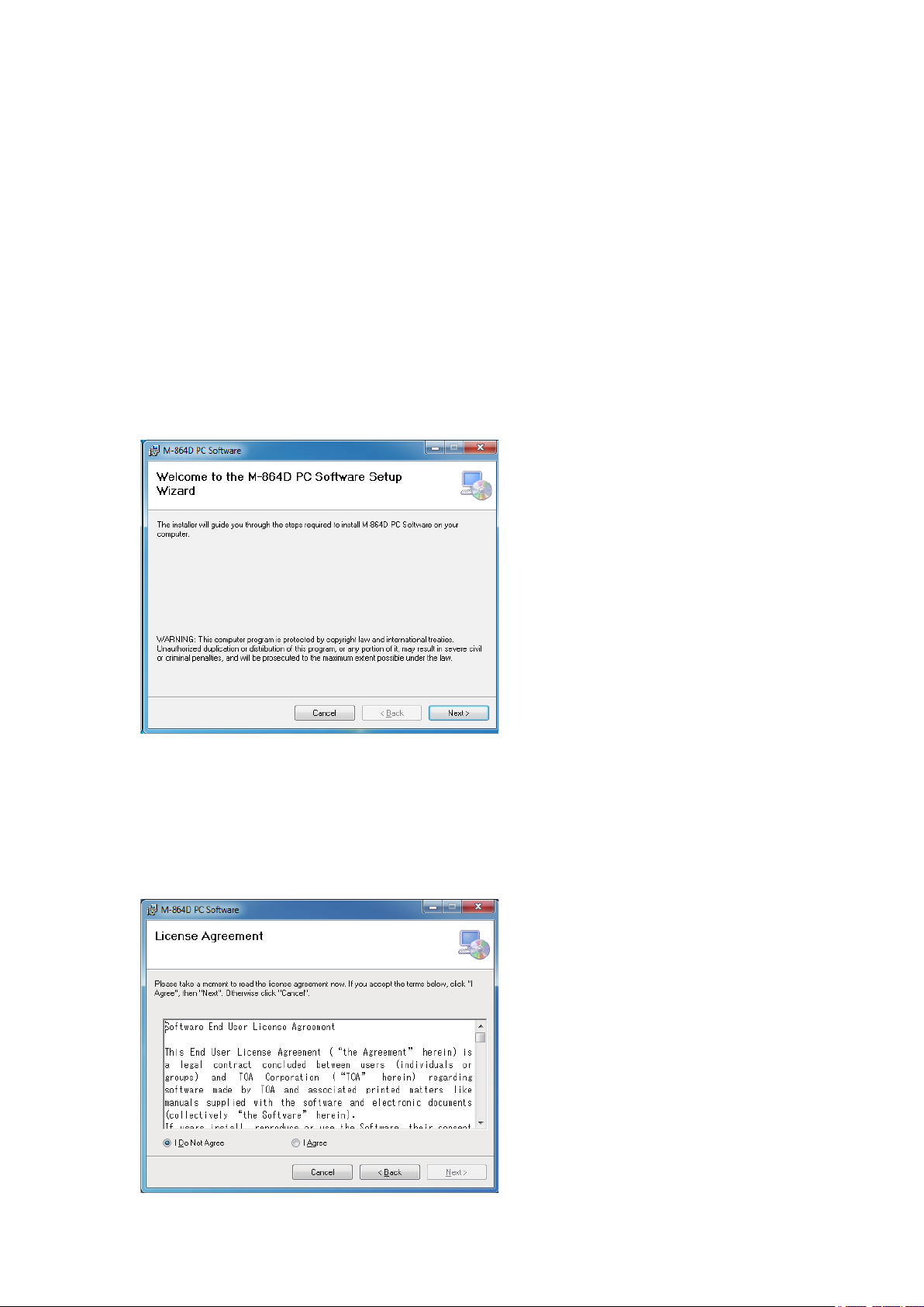
Step 5. Double-click the “setup.exe.”
The following window is displayed.
Step 6. Click the [Next] button.
The following window is displayed.
Check the contents of the License Agreement, then choose the “I Agree” or “I Do Not Agree” radio
button.
Choosing “I Agree” allows to click the [Next] button.
5
Page 6
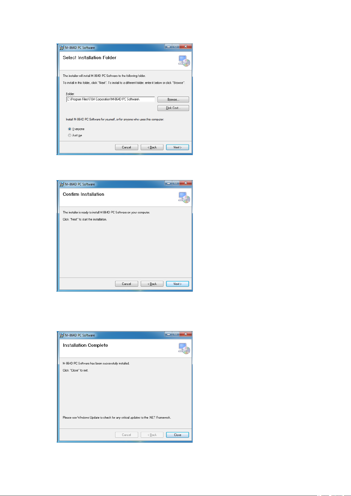
Step 7. Check the contents of the window, then click the [Next] button.
The following window is displayed.
Step 8. If necessary, change the folder into which the software will be installed, then click the [Next] button.
The following window is displayed.
Step 9. Start installation according to the instructions on the screen.
Note
If the .NET Framework is not installed in the PC, follow the on-screen instructions to install it.
Connection to the internet is required.
Step 10. Click the [Close] button after installation completion.
The shortcut icon for the M-864D GUI executable program is stored in the PC’s start menu.
6
Page 7

2.2. Uninstalling the M-864D PC Software
Step 1. Click the Start button on the PC’s desktop, and select [Setting Control Panel].
The “Control Panel” window is displayed.
Step 2. Double-click the following icon.
• Windows Vista and Windows 7: “Programs and Features”
• Windows XP: “Add or Remove Programs”
The currently installed program will then be displayed.
Step 3. Select “M864D PC Software.”
Step 4. Click the following button to uninstall the software.
• Windows Vista and Windows 7: “Uninstall”
• Windows XP: “Delete”
3. STARTING THE SOFTWARE
The following two different methods are available for starting the installed M-864D PC Software:
3.1. Starting from the “Start” Menu
You can start the M-864D PC Software from the start menu.
Click the Start button on the PC’s desktop, and select [Programs TOA Digital Audio Control M-864D
PC Software] to start.
3.2. Starting from the Shortcut Icon
You can start the M-864D PC Software by double-clicking the shortcut icon created on the desktop
after installation completion.
7
Page 8
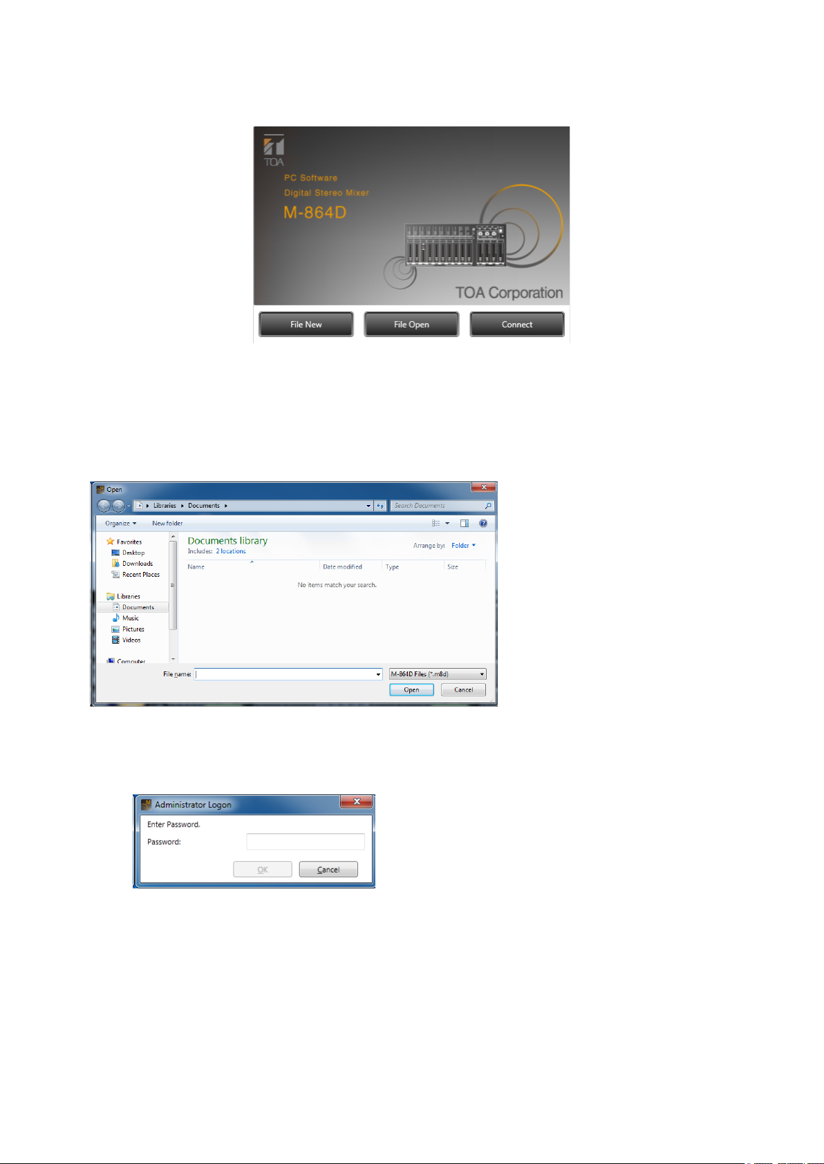
4. INITIAL OPERATION SELECTION SCREEN
Starting the M-864 PC Software displays the Initial Operation Selection screen.
Depending on the job to be done, select the [File New], [File Open], or [Connect] button.
1. File New
The display switches to the Main screen (see p. 11).
2. File Open
The Open dialog is displayed.
Select the le to be opened and click the [Open] button.
The le opens and the display switches to the Main screen (see p. 11).
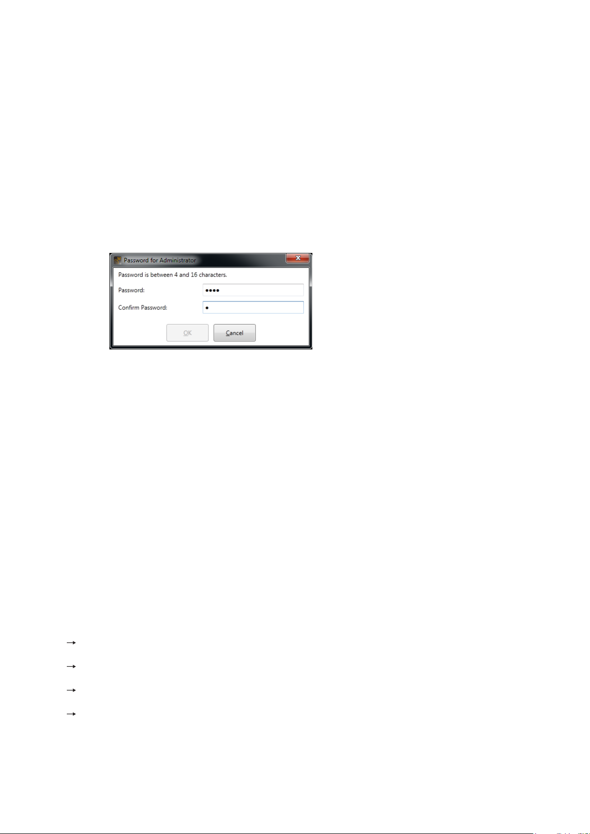
Note: The following logon screen may appear when the le opens:
When this screen appears, the User Level has been set.
Please read the section “Logging on with user level enabled” on p. 114.
8
Page 9
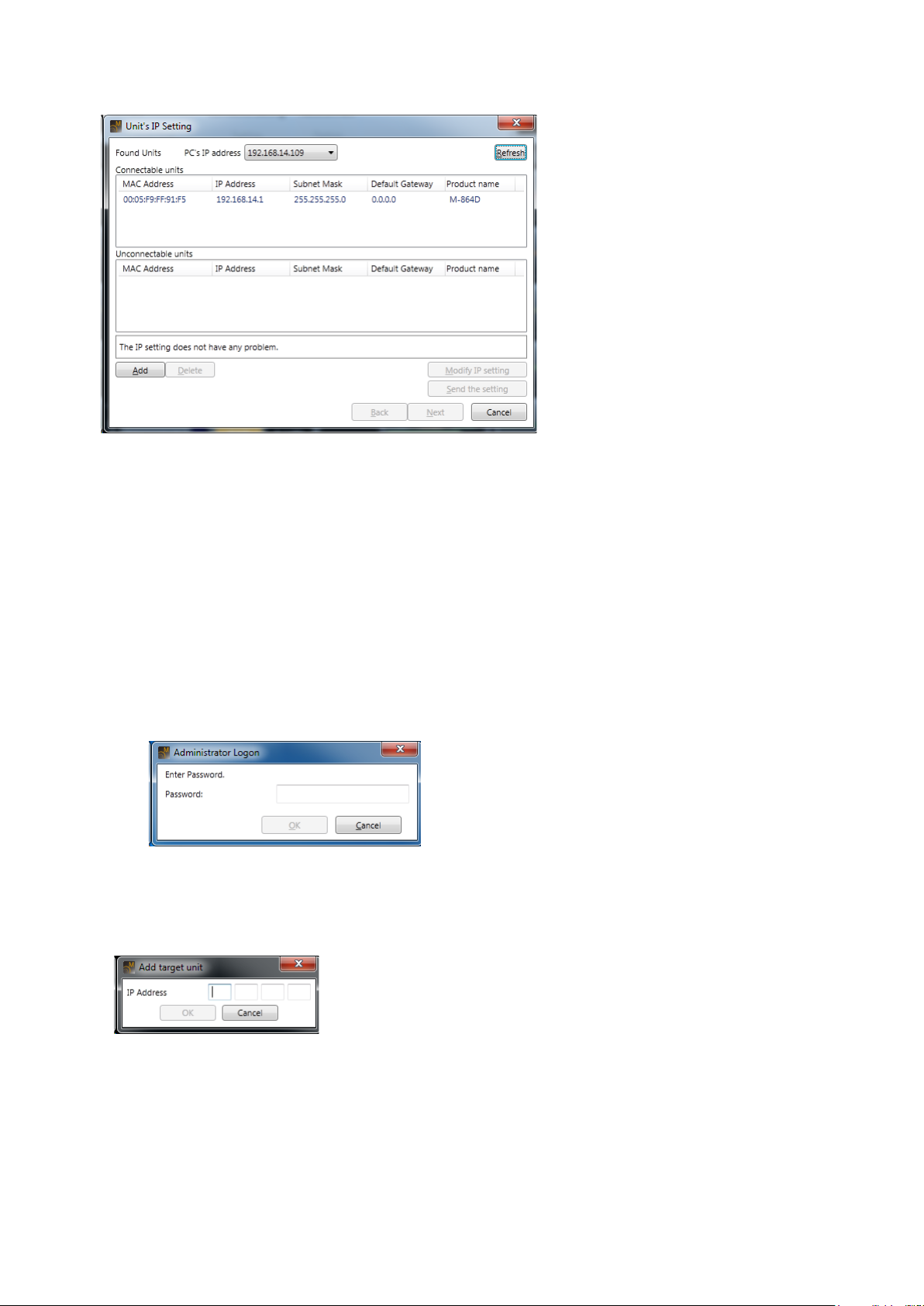
3. Connect
Units are automatically detected and the Unit’s IP Setting dialog is displayed.
Units that are available and not available for communications are displayed in the “Connectable units” and
“Unconnectable units” lists. If no units from which to receive data are shown, click the [Add] button to display
more units. Selecting this button causes the “Add target unit” dialog to be displayed (see the Add target unit
dialog below).
Select the unit from which to receive data from the “Connectable units,” then click the [Next] button to display
the Firmware version check screen.
If the displayed rmware version is old, update the rmware. (See, p. 78, Step 6 in the “Connection
Settings.”
After selecting the unit from which to receive data, click the [Finish] button, and data reception begins,
displaying the communication dialog.
After data reception is completed, clicking the [Completed] button of the Communication Dialog switches the
display to the Main screen (see p. 11).
Note: The following logon screen may appear when the le opens:
When this screen appears, the User Level has been set.
Please read the section “Logging on with user level enabled” on p. 114.
• AddtargetunitDialog
Used to add target units.
Enter the IP address of the unit to be connected.
9
Page 10
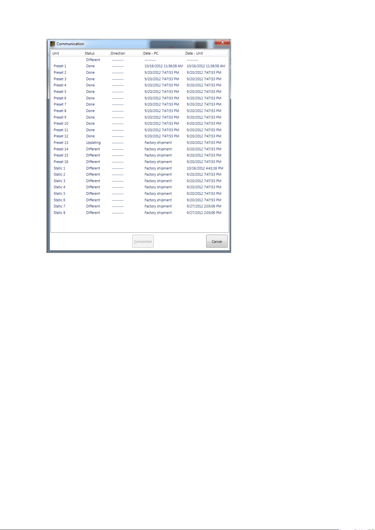
• CommunicationDialog
Reception status is indicated. (See p. 120 "Preset" and p. 120 "Static.")
Select [Cancel] button to return the display to the Initial Operation Selection screen.
10
Page 11
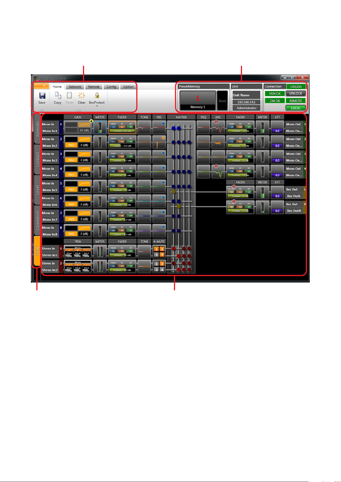
5. MAIN SCREEN AND INDIVIDUAL VIEWS
After initial operation selection settings, the Main screen is displayed.
Menu view
Status view
Main view selector Main view
11
Page 12
5.1. Menu View
The Menu view is located in the upper left section of the Main screen.
Clicking on the individual tabs in the Menu view displays the menu icons related to each corresponding function.
Click on a menu icon to execute its function.
Note: Clicking the ALT key displays the shortcut keys of the ribbon menu.
5.1.1. Menu Term Description
[Application]
New: Creates (sets) a new data le.
Open... : Calls up the existing data le.
Note
When a le is opened, the following logon screen may be displayed.
This screen appears when a user level is set.
(See p. 114, “Logging on with user level enabled.”)
Save: Overwrites the le being edited.
Save As... : Saves the le being edited to the disk under a different name.
Close: Closes the le being edited.
About... : Displays the M-864D PC Software version number.
Exit: Exits the M-864D PC Software.
[Home]
Save: Updates the le being edited.
Copy: Copies the value set for the function box selected on the ow view (see p. 16) to the clipboard.
Paste: Pastes the data in clipboard to the function box selected on the ow view.
Clear: Initializes the value set for the function box selected on the ow view.
Box Protect
Off: Sets no restriction on write to box.
Low: Restricts the operator from changing the parameters set in the box.
Mid: Restricts the operator from changing all settings in the box.
High: Restricts the administrator from changing the parameters set in the box, and the operator from
changing all settings in the box.
12
Page 13

[Network]
Connect: Connects the unit to a PC for online processing. (See p. 75.)
Disconnect: Disconnects the unit from a PC for ofine processing. (See p. 80.)
Note
The unit’s setting does not change while in the ofine state even if it is changed with
a PC.
Connection Setting: Allows you to perform network settings and to designate the unit’s IP address to
which this software can access.
Auto Connect: Makes an automatic connection when the le is opened next time.
[Remote]
Input: Displays the contact input setting dialog. (See p. 82.)
Output: Displays the contact output setting dialog. (See p. 84.)
Setting: Displays the ZM Remote controller setting dialog. (See p. 87.)
Port Setting: Displays the Port Setting screen. (See p. 91.)
Remote Command: Displays the External Control Command Setting screen. (See p. 92.)
[Config]
Name: Displays the unit name setting dialog. (See p. 98.)
Fader: Displays the fader setting dialog. (See p. 99.)
Lock: Displays the lock setting dialog. (See p. 100.)
Preset Memory Setting: Displays the preset memory setting dialog. (See p. 102.)
[Option]
Change Safe: Displays the Change Safe Setting dialog. (See p. 105.)
Security Setting: Sets the user level and the restriction of operations. (See p. 113.)
Maintenance: Displays the Maintenance window. (See p. 110.)
13
Page 14

5.2. Status View
The Status view is located in the upper right section of the Main screen.
The Status view consists of Memory, Unit and Connection views.
Memory View Unit View Connection View
The Status view displays information related to the unit to be set.
5.2.1. Memory view
Displays the name and number of the currently selected Preset Memory (see p. 102). Click “Store” to write to
Preset Memory. Clicking the Preset Memory name and number displays the Memory List panel (see p. 71).
5.2.2. Unit view
Displays the unit’s name and IP address.
5.2.3. Connection view
Displays the unit’s statuses.
• Unit communication connection status
• Unit cooling fan status
• ZM Remote controller status
• Unit’s system lock status
• Remote control status
• Local status
14
Page 15

5.3. Main View
The Main view can be changed with the selection of one of the following 5 different views: Flow view, Operation
view, Level Monitor view, Contact Monitor view, and Remote Monitor view.
5.3.1. Main view selector
Tabs for selecting individual view displays are provided on the left-hand side of the Main view. Clicking on these
tabs switches the Main view display to the selected view.
Remote Monitor view tab
Contact Monitor view tab
Level Monitor view tab
Operation view tab
Flow view tab
Notes
• Depending on the PC’s display size, tabs may be arranged in multiple rows.
• The following tabs cannot be selected while in ofine mode:
· Level Monitor view tab
· Contact Monitor view tab
· Remote Monitor view tab
15
Page 16
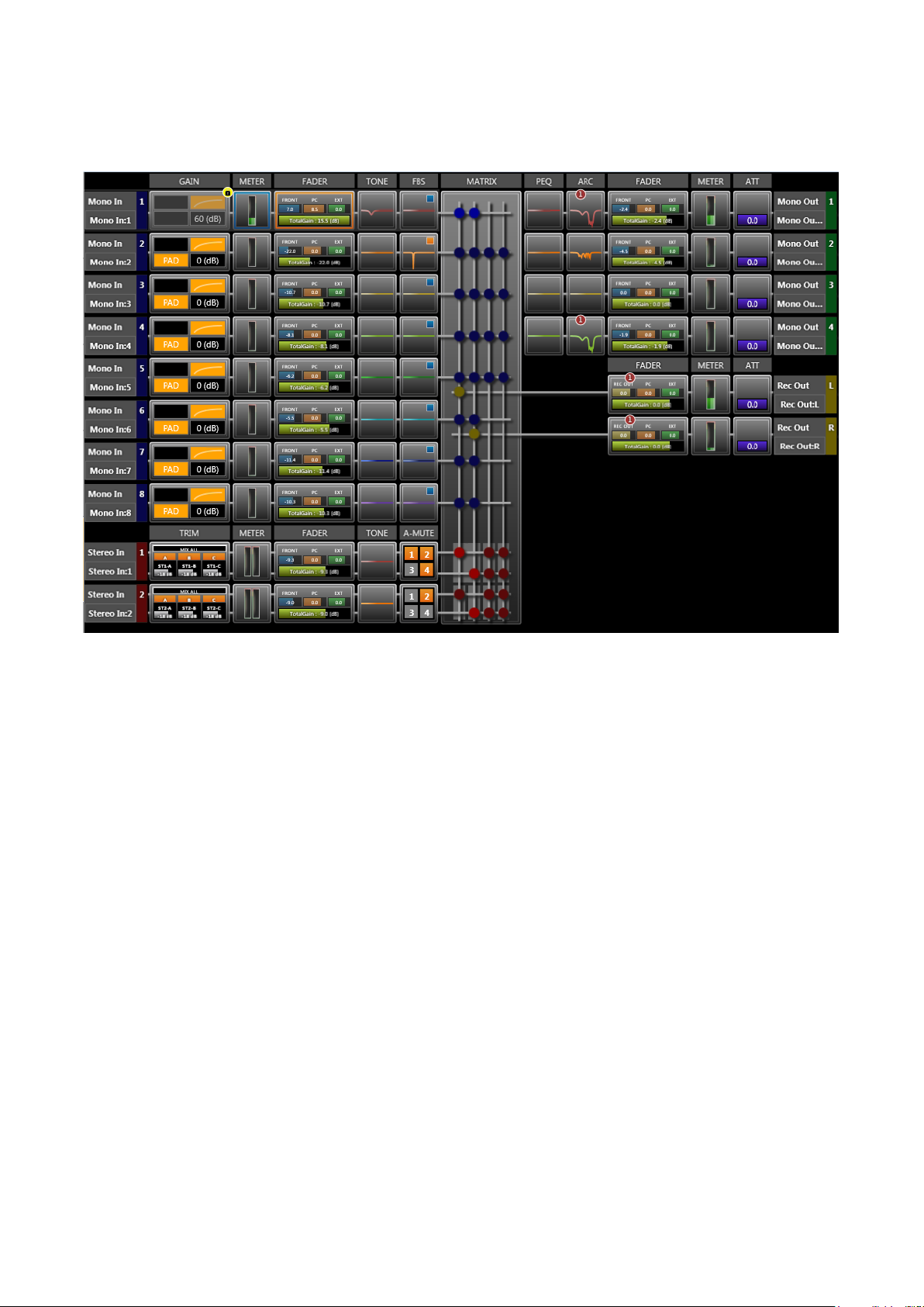
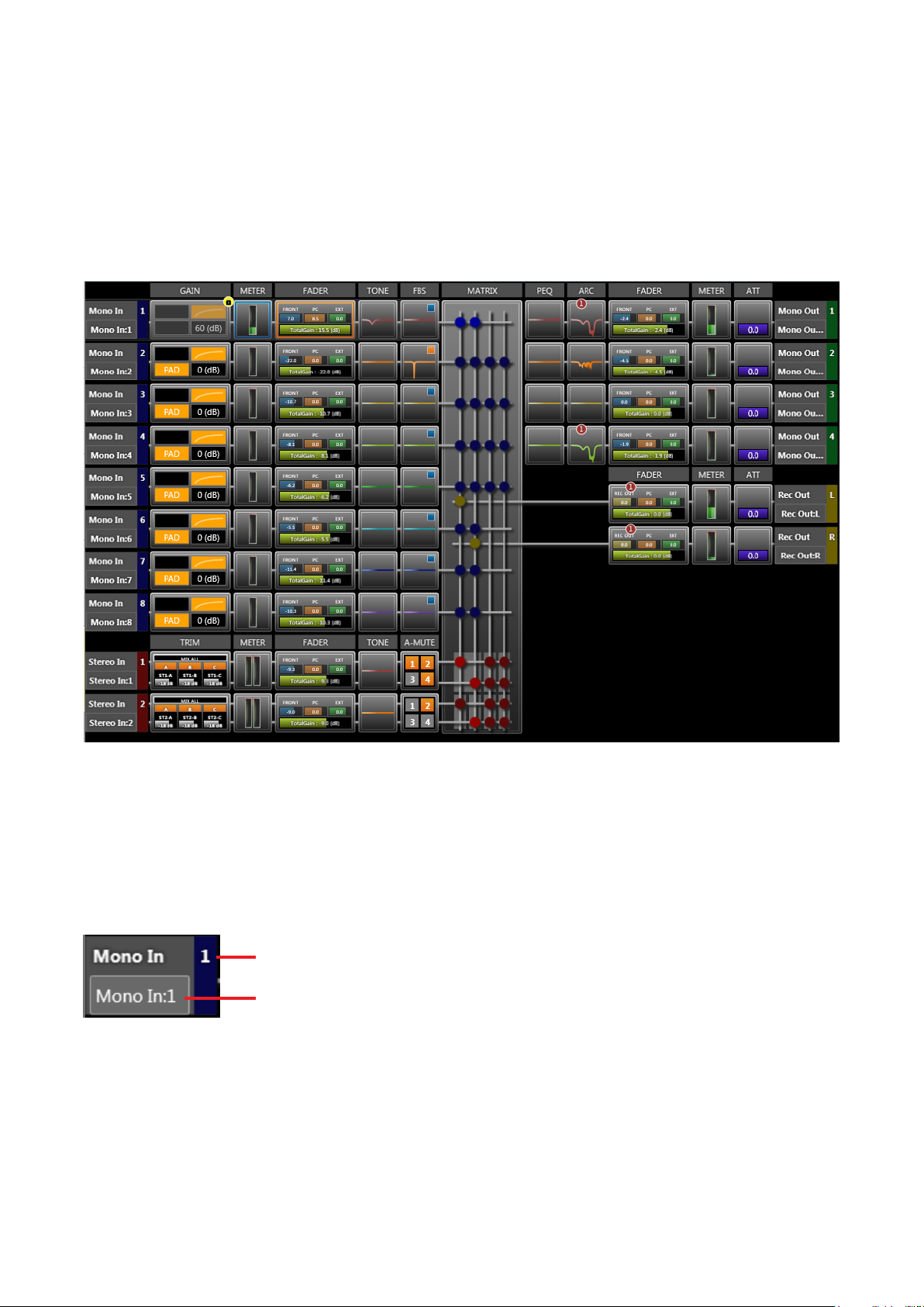
5.3.2. Flow view
Displays the unit’s signal processing image by means of a signal ow consisting of Function and Level Meter
boxes, which indicate the unit’s signal processing operation, and a straight line connecting the input and output.
Signal input is at the left of the centrally located signal ow matrix box, and signal output at the right.
To change signal processing settings, click each of the signal processing function boxes. A pop-up sub-view is
displayed, permitting changes to be entered.
The selected function box is highlighted with an orange frame (except for the Level Meter box, which is shown
with a blue frame).
The following operations can be performed for each function box using the menu displayed by right-clicking
the box.
Data can be copied and pasted by dragging and dropping the box.
Copy: Copies the parameters set for the function box selected on the ow view to the clipboard.
Paste: Pastes the data in clipboard to the function box selected on the ow view.
Clear: Initializes the parameters set for the function box selected on the ow view.
Box Write Protect... :
Off: Sets no restriction on write to box.
Low: Restricts the operator from changing the parameters set in the box.
Mid: Restricts the operator from changing all settings in the box.
High: Restricts the administrator from changing the parameters set in the box, and the operator from
changing all settings in the box.
Note: The above operation cannot be performed on the Level Meter box.
16
Page 17
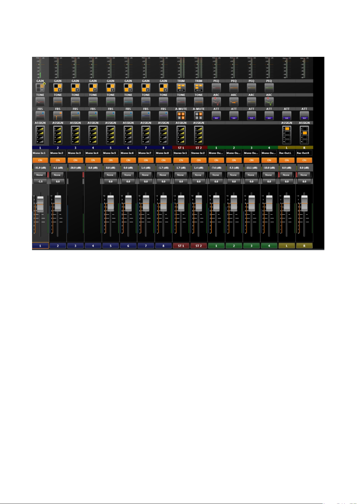
5.3.3. Operation view
Looking like a mixer console, this view is used to operate the unit’s signal processing functions.
To change signal processing settings, click each of the signal processing function boxes. A pop-up sub-view is
displayed, permitting changes to be entered.
The following operations can be performed for each function box using the menu displayed by right-clicking
the box.
Data can be copied and pasted by dragging and dropping the box.
Copy: Copies the parameters set for the function box selected on the operation view to the clipboard.
Paste: Pastes the data in clipboard to the function box selected on the operation view.
Clear: Initializes the parameters set for the function box selected on the operation view.
Box Write Protect... :
Off: Sets no restriction on write to box.
Low: Restricts the operator from changing the parameters set in the box.
Mid: Restricts the operator from changing all settings in the box.
High: Restricts the administrator from changing the parameters set in the box, and the operator from
changing all settings in the box.
Note: The above operation cannot be performed on the Level Meter box.
17
Page 18
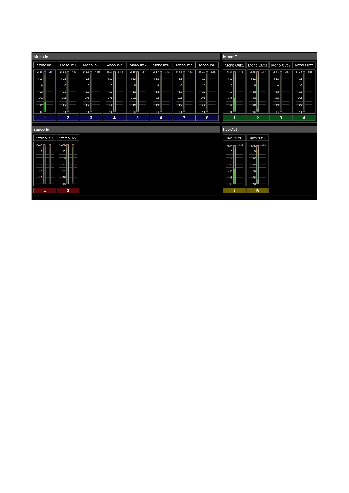
5.3.4. Level monitor view
Monitors the unit’s input and output signal levels. Can only be displayed while in online mode.
Clicking on the Mono In, Stereo In, Mono Out, or Rec Out level meter boxes displayed in the Flow view highlights
the selected box in a blue frame. In the Level Monitor view, the module corresponding to the selected box is
also highlighted in a blue frame.
18
Page 19
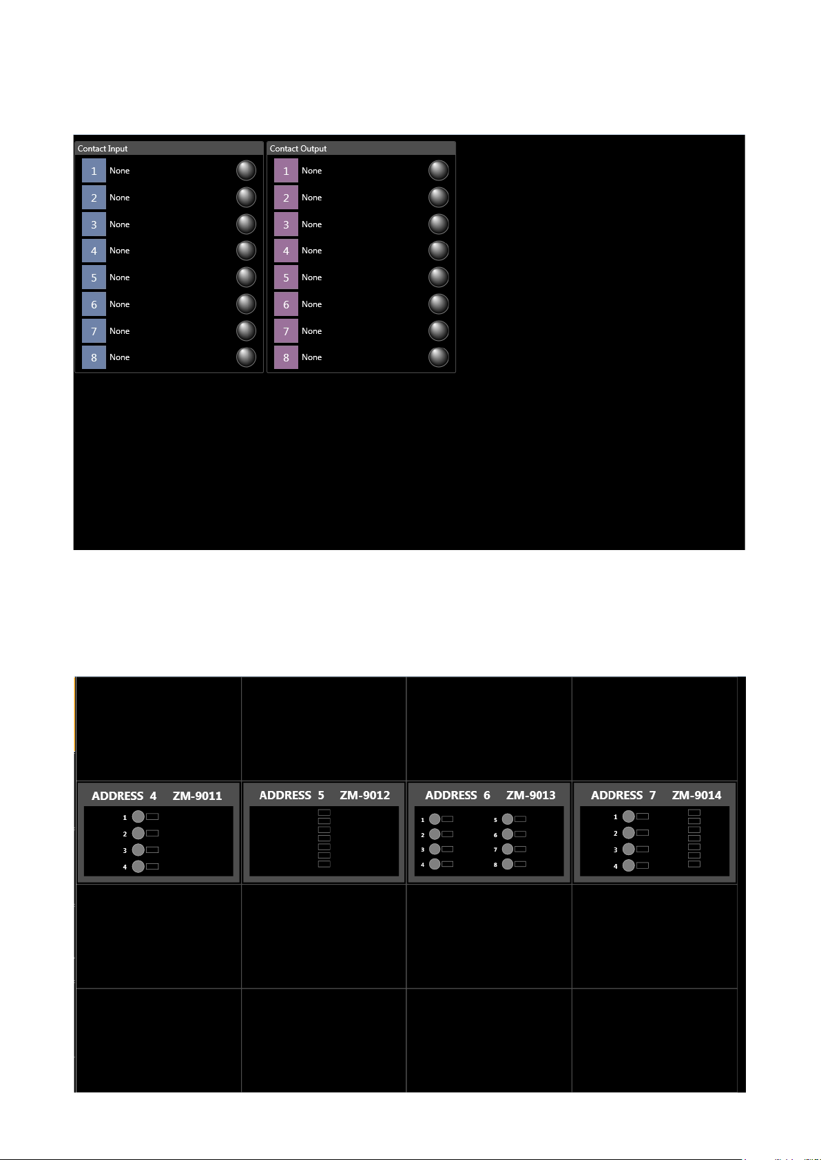
5.3.5. Contact monitor view
Monitors the unit’s contact input and output statuses. Can only be displayed while in online mode.
5.3.6. Remote monitor view
Monitors the operation statuses of the connected ZM Remote controllers connected to the unit. Can only be
displayed while in online mode.
19
Page 20
5.4. Detail Setting View
Use the pop-up sub-view to set signal processing details (parameters, names, etc.).
5.4.1. Pop-up sub-view
Clicking on any signal processing function box in the Flow or Operation views displays a pop-up sub-view that
allows signal processing settings to be changed.
To close the pop-up sub-view, click the [Close] button located in the upper right corner of the view, or click
outside the view.
Pop-up sub-view
20
Page 21
6. MAIN VIEW
Details of each view within the Main view are explained below:
6.1. Flow View
Displays the unit’s signal processing image by means of a signal ow consisting of Function and Level Meter
boxes, which indicate the unit’s signal processing operation, and a straight line connecting the input and output.
Signal input section is at the left of the centrally located signal ow matrix box, and signal output section at the
right.
6.1.1. Monaural input
The 8-channel monaural input has the following boxes:
[Channel information]
The monaural input’s channel numbers and channel names are displayed.
Channel No.
Channel name
21
Page 22
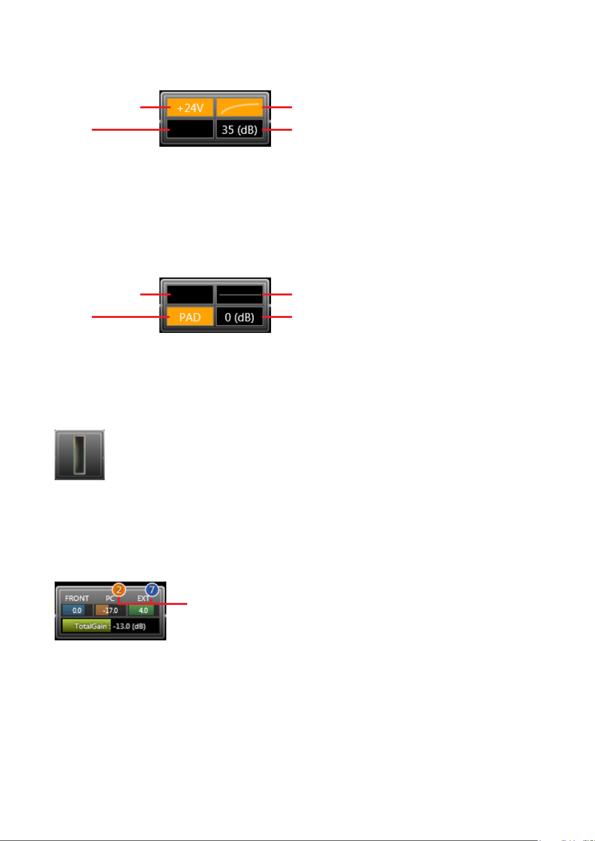
[Gain]
Statuses of the phantom power ON/OFF, PAD, low-cut lter and gain are displayed.
(1) Phantom power (3) Low-cut lter
(2) PA D (4) Gain
1. Phantom Power
Displayed in orange when the phantom power is
ON, and in black when the phantom power is OFF.
2. PAD
Displayed in orange when PAD is ON, and in black
when PAD is OFF.
The following display shows the phantom power is OFF, PAD is ON, low-cut lter is OFF and gain is 0 dB:
(1) Phantom power (3) Low-cur lter
(2) PA D (4) Gain
For gain settings, see p. 47 “Function Box.”
[Level meter]
Displays the monaural input level.
The post-processing gain level is displayed.
3. Low-Cut Filter
Displays a curve as shown in the gure above
when the low-cut lter is ON, or a straight line as
shown in the gure below when OFF.
4. Gain
Displays gain values.
The level meter box is only displayed while in online mode.
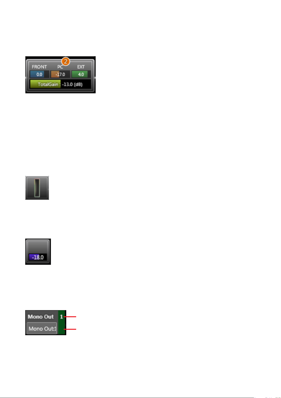
[Fader]
Displays individual gain values of the FRONT fader (fader on the unit’s front panel), PC VOL. (PC software
fader) and EXT VOL. (external control of the ZM Remote controller, etc.), as well as their total gain value.
When grouping has been set, the corresponding group number is displayed.
Group number
Each gain is also indicated by a bar extending from the left.
Faders set to “Disable” in the fader settings (see p. 99) are not displayed.
The FRONT fader gain is displayed only while in online mode.
When in ofine mode, the total gain is obtained as 0 dB of the FRONT fader gain.
Note: Faders set to “Disable” are xed at 0 dB gain.
For fader settings, see p. 49, “Function Box.”
22
Page 23

[Tone]
Roughly displays the frequency characteristics curve set with the tone control.
Frequency characteristics are indicated by a at straight line when BASS, MID and TREBLE gains are all set
to 0 dB.
For tone settings, see p. 52, “Function Box.”
[FBS]
Roughly displays the frequency characteristics curve of the Feedback Suppressor (FBS) lter.
For FBS settings, see p. 54, “Function Box.”
23
Page 24
6.1.2. Stereo input
Two-channel stereo inputs have the following boxes:
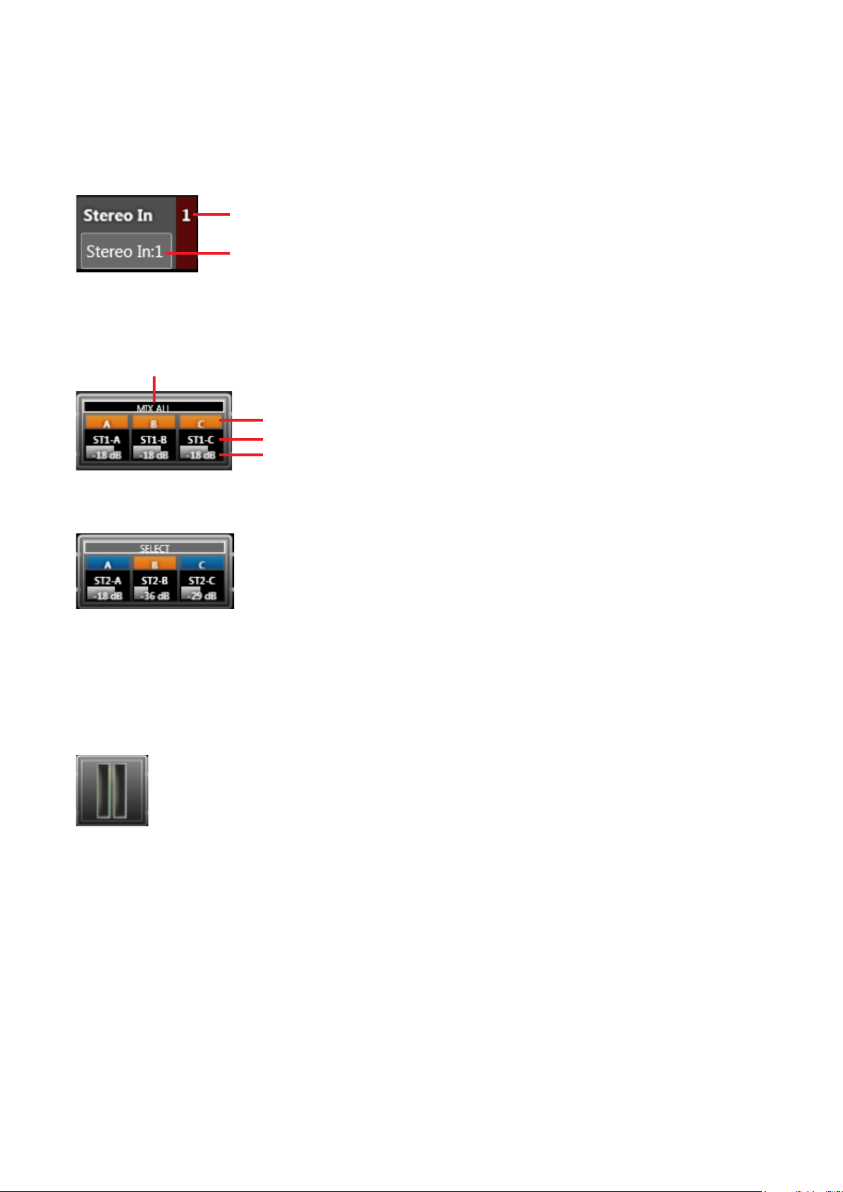
[Channel information]
The stereo input’s channel numbers and channel names are displayed.
Channel No.
Channel name
[Trim]
Displays MIX ALL/SELECT mode, and ON/OFF status, name and gain of A, B and C inputs.
Mode (MIX ALL or SELECT)
ON/OFF status (orange: ON, blue: OFF)
Name
Gain
Each gain is also indicated by a gray bar extending from the left.
The gure below shows Input B is selected and its gain is set to –36 dB.
Note: ON/OFF status and gains for both L and R stereo channels are interlocked.
For trim settings, see p. 48, “Function Box.”
[Level meter]
Displays post-trim processing stereo input level.
The Level Meter box is only displayed while in online mode.
24
Page 25

[Fader]
Displays individual gain values of the FRONT fader (fader on the unit’s front panel), PC VOL. (setting software
fader) and EXT VOL. (external control of the ZM Remote controller, etc.), as well as their total gain value.
When grouping has been set, the corresponding group number is displayed.
Group number
Each gain is also indicated by a bar extending from the left.
Note: Gains for both L and R stereo channels are interlocked.
Faders set to “Disable” in the fader settings (see p. 99) are not displayed.
The FRONT fader gain is displayed only while in online mode.
When in ofine mode, the total gain is obtained as 0 dB of the FRONT fader gain.
Note: Faders set to “Disable” are xed at 0 dB gain.
For fader settings, see p. 49, “Function Box.”
[Tone]
Roughly displays the frequency characteristic curve set with the tone control.
Frequency characteristics are indicated by a at straight line when BASS, MID and TREBLE gains are all set
to 0 dB.
Note: Tone control settings for both L and R stereo channels are interlocked.
For tone settings, see p. 52, “Function Box.”
[Auto-Mute]
Displays the Auto-Mute ON/OFF status for output channels 1 – 4.
Orange indicates ON and gray indicates OFF.
(In the gure below, outputs 1 and 2 are ON, and outputs 3 and 4 are OFF.)
Note: ON/OFF settings here have nothing to do with output assignment.
Use the matrix function boxes for output signal assignment (see p. 59).
Note: Auto-Mute ON/OFF settings for both L and R stereo channels are interlocked.
For Auto-Mute ON/OFF settings, see p. 57, “Function Box.”
25
Page 26
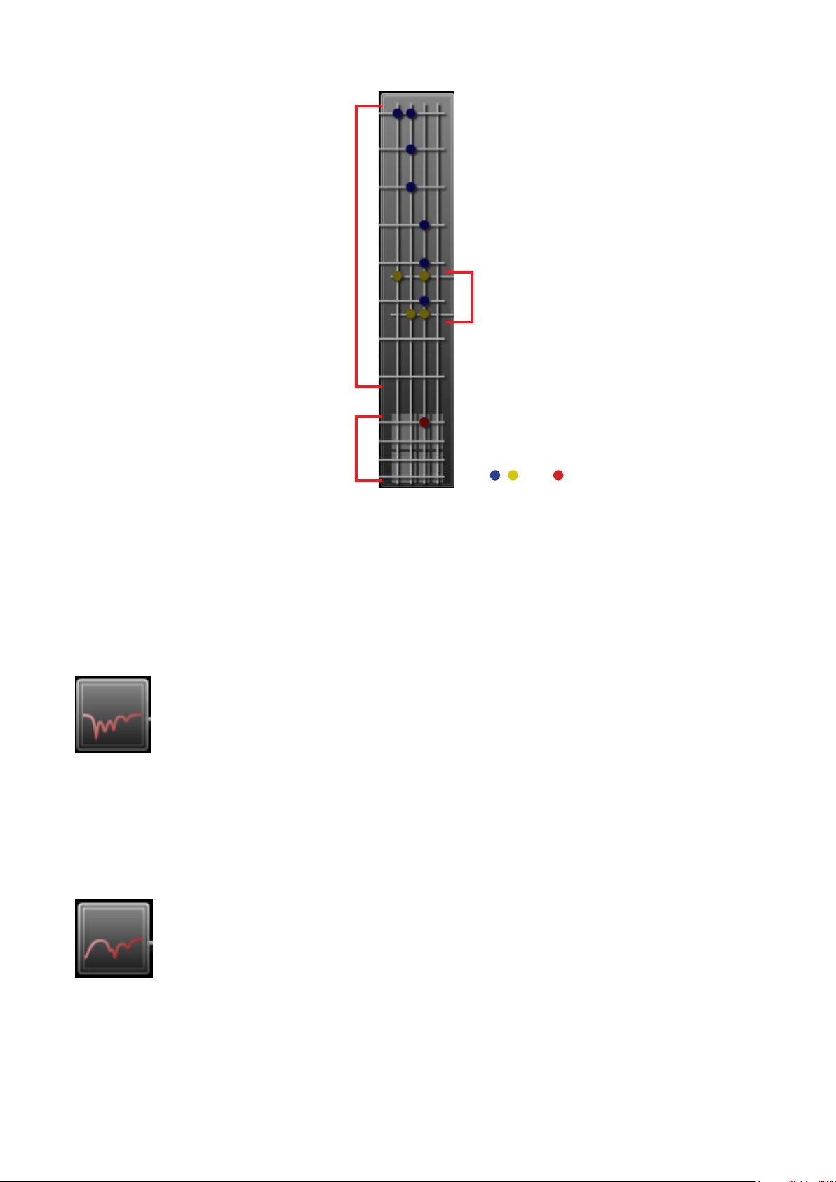
6.1.3. Matrix
• Displays the monaural input (1 – 8) to
monaural output (1 – 4) assignment.
• During the Auto-Mute operation, the
monaural input working as the mute
trigger is displayed with a ashing point(s).
(Only while in online mode)
• Displays the stereo input (1 – 2) to
monaural output (1 – 4) assignment.
• The stereo input being muted by the AutoMute function is displayed with a ashing
point(s). (Only while in online mode)
• Displays the monaural output (1 – 4) to
recording output (1 – 2) assignment.
, , and : Signal assignment set
For Matrix settings, see p. 59, “Function Box.”
6.1.4. Monaural output
Four-channel monaural outputs have the following boxes:
[PEQ (Parametric Equalizer)]
Roughly displays the frequency characteristics curve set with the PEQ.
Frequency characteristics are indicated by a at straight line when all gains are set to 0 dB.
For PEQ settings, see p. 63, “Function Box.”
[ARC (Automatic Resonance Control)]
Roughly displays the frequency characteristics curve of the ARC sound eld compensating lter.
Frequency characteristics are indicated by a at straight line when all sound eld compensating lter gains are
set to 0 dB.
For ARC operation settings, see p. 65, “Function Box.”
26
Page 27
[Fader]
Displays individual gain values of the FRONT fader (fader on the unit’s front panel), PC VOL. (setting software
fader) and EXT VOL. (external control of the ZM Remote controller, etc.), as well as their total gain value.
When grouping has been set, the corresponding group number is displayed.
Each gain is also indicated by a bar extending from the left.
Faders set to “Disable” in the fader settings (see p. 99) are not displayed.
The FRONT fader gain is displayed only while in online mode.
When in ofine mode, the total gain is obtained as 0 dB of the FRONT fader gain.
Note: Faders set to “Disable” are xed at 0 dB gain.
For fader settings, see p. 49, “Function Box.”
[Level meter]
Displays the monaural output level.
The pre-attenuator processing level is displayed.
The level meter box is only displayed while in online mode.
[Attenuator]
Displays attenuator gains (dB).
Gains are also indicated by a bar extending from the left.
For attenuator settings, see p. 70, “Function Box.”
[Channel information]
The monaural output’s channel numbers and channel names are displayed.
Channel No.
Channel name
27
Page 28
6.1.5. Recording output
Two-channel recording outputs have the following boxes:
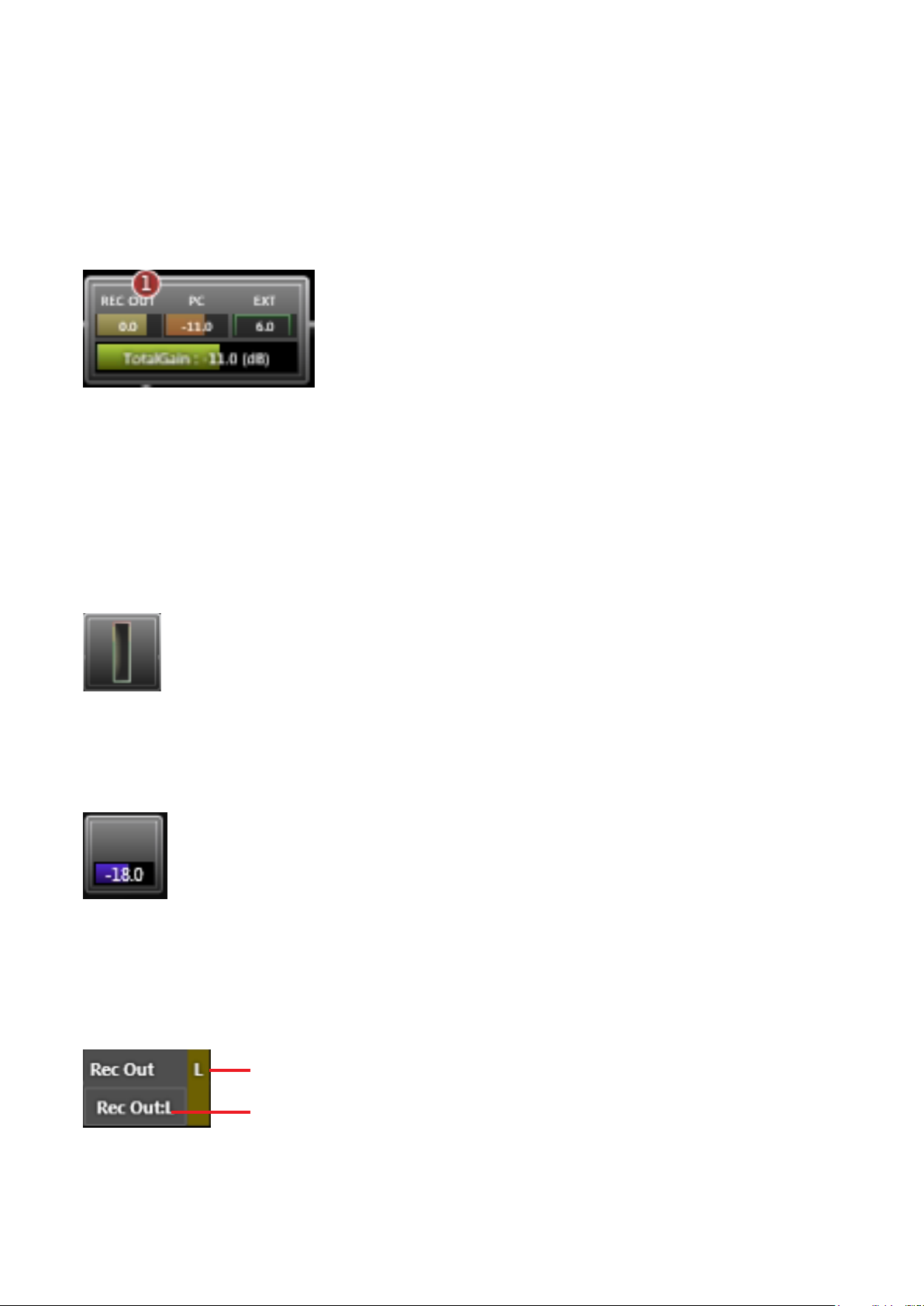
[Fader]
Displays individual gain values of the REC OUT VOL. (volume control on the unit’s front panel), PC VOL. (PC
software fader) and EXT VOL. (external control of the ZM Remote controller, etc.), as well as their total gain
value.
When grouping has been set, the corresponding group number is displayed.
Each gain is also indicated by a bar extending from the left.
Faders set to “Disable” in the conguration settings (see p. 99) are not displayed.
Note: Faders set to “Disable” are xed at 0 dB gain.
For fader settings, see p. 49, “Function Box.”
[Level meter]
Displays the recording output level.
The pre-attenuator processing level is displayed.
The level meter box is only displayed while in online mode.
[Attenuator]
Displays attenuator gains (dB).
Gains are also indicated by a bar extending from the left.
For attenuator settings, see p. 70, “Function Box.”
[Channel information]
The recording output’s channel numbers and channel names are displayed.
Channel No. (L, R)
Channel name
28
Page 29
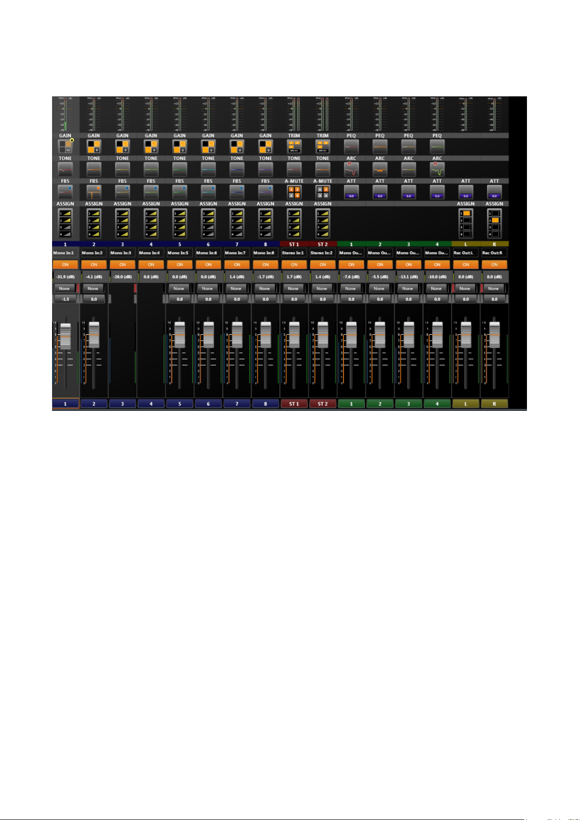
6.2. Operation View
Looking like a mixer console, this view is used to operate the unit’s signal processing functions.
29
Page 30
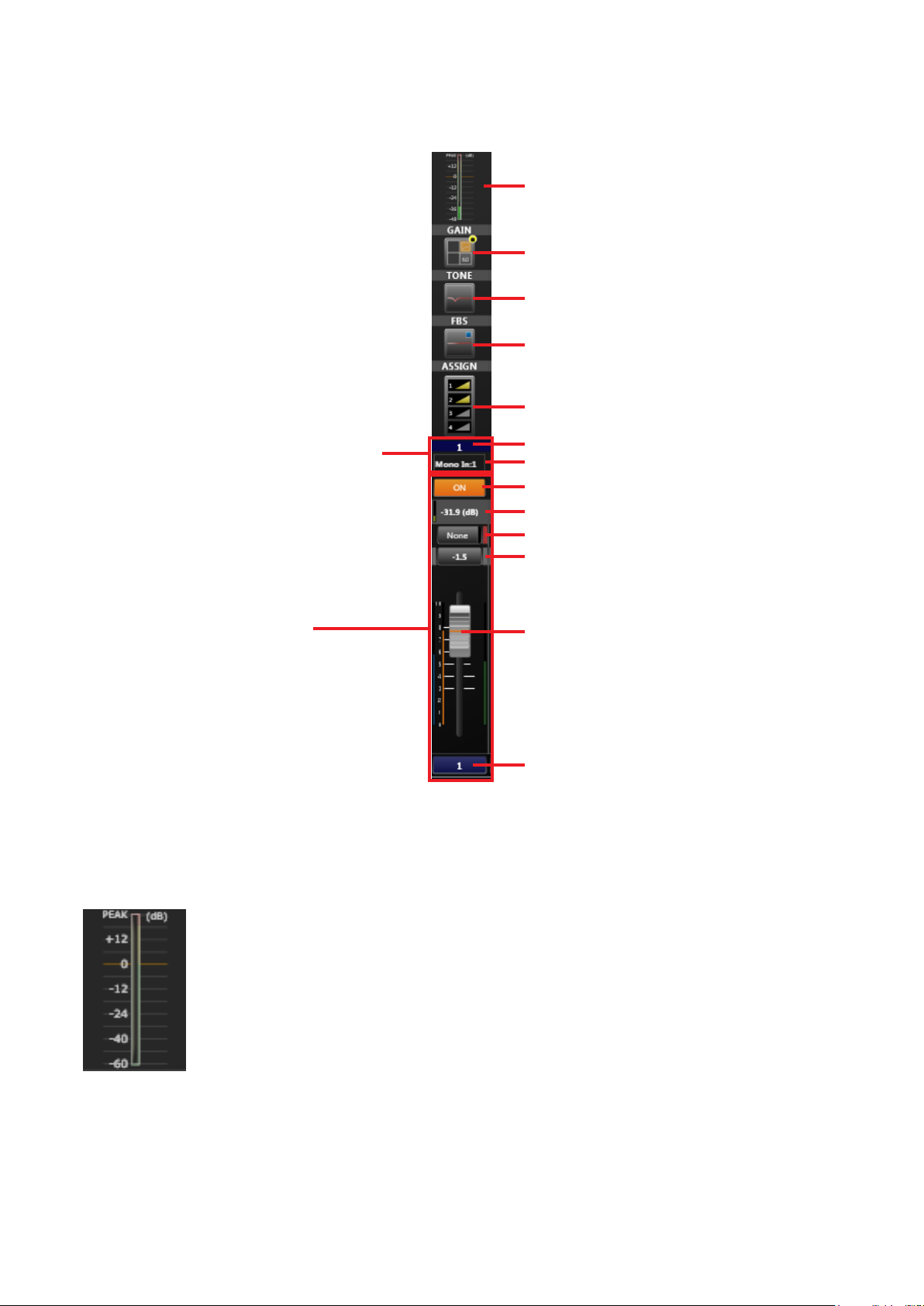
6.2.1. Monaural input
The 8-channel monaural input is comprised of the following elements shown in the gure below:
Level meter
Gain
Tone
FBS
Assign
Channel information
Fader box
[Level meter]
Displays the monaural input level.
The post-processing gain level is displayed.
Channel No.
Channel name
Channel ON/OFF button
Total gain
Grouping No.
PC fader gain
PC fader
Fader button
The level meter is only displayed while in online mode.
30
Page 31

[Gain]
Statuses of the phantom power ON/OFF, PAD, low-cut lter and gain are displayed.
(1) Phantom power (3) Low-cur lter
(2) PA D
1. Phantom Power
Displayed in orange when the phantom power is
ON, and in black when the phantom power is OFF.
2. PAD
Displayed in orange when PAD is ON, and in black
when PAD is OFF.
The following display shows the phantom power is OFF, PAD is ON and low-cut lter is OFF, gain is 0 dB:
For gain settings, see p. 47, “Function Box.”
[Tone]
Roughly displays the frequency characteristics curve set with the tone control.
(4) Gain
3. Low-Cut Filter
Displayed as shown in the gure above when the
low-cut lter is ON, and as shown in the gure
below when the lter is OFF.
4. Gain
Displays gain values.
Frequency characteristics are indicated by a at straight line when BASS, MID and TREBLE gains are all set
to 0 dB.
For tone settings, see p. 52, “Function Box.”
[FBS]
Roughly displays the frequency characteristics curve of the Feedback Suppressor (FBS) lter.
For FBS settings, see p. 54, “Function Box.”
31
Page 32

[Assign]
Displays the monaural output (1 – 4) assignment.
A yellow triangle is displayed if Assign is set to ON, and a gray triangle if set to OFF.
The triangle varies in size depending on gain.
For Assign settings, see p. 61, “Function Box.”
[Channel information]
The monaural input’s channel numbers and channel names are displayed.
[Channel ON/OFF button]
Switches the channel to ON or OFF.
This setting interlocks with the grouping setting for EXT VOL.
[Total gain]
Displays a total gain value of the FRONT fader (fader on the unit’s front panel) gain, PC VOL. (PC software
fader) gain and EXT VOL. (external ZM Remote controller, etc.) gain.
The green bar on the left indicates total gain value.
[Grouping number]
Displays the PC (software) fader’s grouping number.
Clicking this button opens the dialog for selecting the grouping number.
The color corresponding to the group is displayed to the right of the grouping
number.
Further, the grouping settings for EXT VOL. gains (external ZM Remote
controller, etc.) are displayed far right of the box in the color corresponding to
the group.
Grouping setting for EXT VOL. gain
(Figure at left shows Group 7 settings.)
Note: Displayed in black when no groups have been set.
PC fader grouping number
Group No. Color
None
1
2
3
4
5
6
7
8
9
10
Black
Red
Orange
Yell o w
Yellow-green
Green
Light blue
Blue
Dark blue
Purple
Gray
Note: The “None” indication is displayed when no groups have been set.
32
Page 33

[PC fader gain]
Displays PC software fader gains in dB. Clicking the box displays the dialog for gain settings, allowing gain
values to be entered. The gain is interlocked with the fader shown below.
[PC fader]
The PC software fader is operational and interlocked with the PC fader gains shown above.
The blue bar at left indicates the FRONT fader (fader on the unit’s front panel) gains.
The green bar at right indicates the EXT VOL. (external ZM Remote controller, etc.) gains.
FRONT fader gain bar EXT VOL. gain bar
Faders set to “Disable” in the fader settings (see p. 99) are not displayed.
The FRONT fader gain is displayed only while in online mode.
When in ofine mode, the total gain is obtained as 0 dB of the FRONT fader gain.
Note: Faders set to “Disable” are xed at 0 dB gain.
[Fader button]
Clicking this button displays the pop-up sub-view for fader detail settings, allowing the fader settings to be
changed. (See p. 49.)
33
Page 34

6.2.2. Stereo input
Two-channel stereo inputs are comprised of the following elements in the gure shown below:
Level meter
Trim
Tone
Auto mute
Assign
Channel information
Fader box
[Level meter]
Displays the stereo input level.
The post-Trim processing level is displayed.
Channel No.
Channel name
Channel ON/OFF button
Total gain
Grouping No.
PC fader gain
PC fader
Fader button
The level meter is only displayed while in online mode.
34
Page 35

[Trim]
Displays MIX ALL/SELECT mode, and ON/OFF status of A, B and C inputs.
Input A ON/OFF status
Input C ON/OFF status
Note: Inputs A, B and C are displayed in orange when ON and black when OFF.
Status is displayed as shown in the following gure when in SELECT mode.
Note: This display shows that Input C is selected.
For trim settings, see p. 48, “Function Box.”
[Tone]
Roughly displays the frequency characteristics curve set with the tone control.
Input B ON/OFF status
Mode (MIX ALL or SELECT)
Frequency characteristics are indicated by a at straight line when BASS, MID and TREBLE gains are all set
to 0 dB.
For tone settings, see p. 52, “Function Box.”
[Auto-Mute]
Displays the Auto-Mute ON/OFF status for output channels 1 – 4.
Orange indicates ON and gray indicates OFF.
(In the gure below, outputs 1 and 2 are ON, and outputs 3 and 4 are OFF.)
Note: ON/OFF settings here have nothing to do with output assignment.
Use the matrix function boxes for output signal assignment (see p. 59).
Note: Auto-Mute ON/OFF settings for both L and R stereo channels are interlocked.
For Auto-Mute ON/OFF settings, see p. 57, “Function Box.”
35
Page 36

[Assign]
Displays the monaural output (1 – 4) assignment.
A yellow triangle is displayed if Assign is set to ON, and a gray triangle if set to OFF.
The triangle varies in size depending on gain.
For Assign settings, see p. 61, “Function Box.”
[Channel information]
The stereo input’s channel numbers and channel names are displayed.
[Channel ON/OFF button]
Switches the channel to ON or OFF.
This setting interlocks with the grouping setting for EXT VOL.
[Total gain]
Displays a total gain value of the FRONT fader (fader on the unit’s front panel) gain, PC VOL. (PC software
fader) gain and EXT VOL. (external ZM Remote controller, etc.) gain.
The green bar on the left indicates total gain value.
Note: Gains for both L and R stereo channels are interlocked.
[Grouping number]
Displays the PC (software) fader’s grouping number.
Clicking this button opens the dialog for selecting the grouping number.
The color corresponding to the group is displayed to the right of the grouping
number.
Further, the grouping settings for EXT VOL. gains (external control of the
ZM Remote controller, etc.) are displayed far right of the box in the color
corresponding to the group.
Grouping setting for EXT VOL. gain
(Figure at left shows Group 7 settings.)
Note: Displayed in black when no groups have been set.
PC fader grouping number
Group No. Color
None
1
2
3
4
5
6
7
8
9
10
Black
Red
Orange
Yell o w
Yellow-green
Green
Light blue
Blue
Dark blue
Purple
Gray
Note: The “None” indication is displayed when no groups have been set.
[PC fader gain]
Displays PC software fader gains in dB.
Clicking the box displays the dialog for gain settings, allowing gain values to be entered.
The gain is interlocked with the fader shown on the next page.
36
Page 37

[PC fader]
The PC software fader is operational and interlocked with the PC fader gains on the previous page.
The blue bar at left indicates the FRONT fader (fader on the unit’s front panel) gains.
The green bar at right indicates the EXT VOL. (external control of the ZM Remote controller, etc.) gains.
FRONT fader gain bar
Faders set to “Disable” in the fader settings (see p. 99) are not displayed.
The FRONT fader gain is displayed only while in online mode.
When in ofine mode, the total gain is obtained as 0 dB of the FRONT fader gain.
Note: Faders set to “Disable” are xed at 0 dB gain.
[Fader button]
Clicking this button displays the pop-up sub-view for fader detail settings, allowing the fader settings to be
changed. (See p. 49.)
EXT VOL. gain bar
37
Page 38

6.2.3. Monaural Output
The 4-channel monaural output is comprised of the following elements shown in the gure below:
Level meter
PEQ (Parametric equalizer)
ARC (Automatic resonance control)
Attenuator
Channel information
Fader box
[Level meter]
Displays the monaural output level.
The pre-attenuator processing level is displayed.
Channel No.
Channel name
Channel ON/OFF button
Total gain
Grouping No.
PC fader gain
PC fader
Fader button
The level meter is only displayed while in online mode.
38
Page 39

[PEQ (Parametric equalizer)]
Roughly displays the frequency characteristics curve set with the PEQ.
Frequency characteristics are indicated by a at straight line when all gains are set to 0 dB.
For PEQ settings, see p. 63, “Function Box.”
[ARC (Automatic resonance control)]
Roughly displays the frequency characteristics curve of the ARC sound eld compensating lter.
Frequency characteristics are indicated by a at straight line when all sound eld compensating lters are set
to 0 dB gain.
For ARC operation settings, see p. 65, “Function Box.”
[Attenuator]
Displays attenuator gains (dB).
Gains are also indicated by a bar extending from the left.
For attenuator settings, see p. 70, “Function Box.”
[Channel information]
The monaural output’s channel numbers and channel names are displayed.
[Channel ON/OFF button]
Switches the channel to ON or OFF.
This setting interlocks with the grouping setting for EXT VOL.
[Total gain]
Displays a total gain value of the FRONT fader (fader on the unit’s front panel) gain, PC VOL. (PC software
fader) gain and EXT VOL. (external ZM Remote controller, etc.) gain.
The green bar at left indicates total gain value.
39
Page 40

[Grouping number]
Displays the PC (software) fader’s grouping number.
Clicking this button opens the dialog for selecting the grouping number.
The color corresponding to the group is displayed to the right of the grouping
number.
Further, the grouping settings for EXT VOL. gains (external control of the
ZM Remote controller, etc.) are displayed far right of the box in the color
corresponding to the group.
Grouping setting for EXT VOL. gains
(Figure at left shows Group 1 settings.)
Note: Displayed in black when no groups have been set.
PC fader grouping number
Group No. Color
None
1
2
3
4
5
6
7
8
9
10
Black
Red
Orange
Yell o w
Yellow-green
Green
Light blue
Blue
Dark blue
Purple
Gray
Note: The “None” indication is displayed when no groups have been set.
[PC fader gain]
Displays PC software fader gains in dB. Clicking the box displays the dialog for gain settings, allowing gain
values to be entered. The gain is interlocked with the fader shown below.
[PC fader]
The PC software fader is operational and interlocked with the PC fader gains (mentioned above).
The blue bar at left indicates the FRONT fader (fader on the unit’s front panel) gains.
The green bar at right indicates the EXT VOL. (external control of the ZM Remote controller, etc.) gains.
EXT VOL. gain barFRONT fader gain bar
Faders set to “Disable” in the fader settings (see p. 99) are not displayed.
The FRONT fader gain is displayed only while in online mode.
When in ofine mode, the total gain is obtained as 0 dB of the FRONT fader gain.
Note: Faders set to “Disable” are xed at 0 dB gain.
40
Page 41

[Fader button]
Clicking this button displays the pop-up sub-view for fader detail settings, allowing the fader settings to be
changed. (See p. 49.)
6.2.4. Recording output
The 2-channel recording output is comprised of the following elements shown in the gure below:
Level meter
Attenuator
Assign
Channel information
Fader box
[Level meter]
Displays the recording output level.
The pre-attenuator processing level is displayed.
Channel No.
Channel name
Channel ON/OFF button
Total gain
Grouping No.
PC fader gain
PC fader
Fader button
The level meter is only displayed while in online mode.
41
Page 42

[Attenuator]
Displays attenuator gains (dB).
Gains are also indicated by a bar extending from the left.
For attenuator settings, see p. 70, “Function Box.”
[Assign]
Displays the monaural output (1 – 4) assignment.
Displayed in orange if the monaural output assignment is set to ON, and in black if set to OFF.
Note: This gure shows that monaural outputs 1 and 3 are assigned.
For Assign settings, see p. 61, “Function Box.”
[Channel information]
The recording output’s channel numbers and channel names are displayed.
[Channel ON/OFF button]
Switches the channel to ON or OFF.
This setting interlocks with the grouping setting for EXT VOL.
[Total gain]
Displays individual gain values of the FRONT fader (fader on the unit’s front panel), PC VOL. (PC software
fader) and EXT VOL. (external control of the ZM Remote controller, etc.), as well as their total gain value.
The green bar at left indicates total gain value.
42
Page 43

[Grouping number]
Displays the PC (software) fader’s grouping number.
Clicking this button opens the dialog for selecting the grouping number.
The color corresponding to the group is displayed to the right of the grouping
number.
Further, the grouping settings for REC OUT VOL. gains (REC OUT volume
control on the unit’s front panel) are displayed far left of the box, and those for
EXT VOL. gains (external control of the ZM Remote controller) are displayed
far right in the color corresponding to the group.
Grouping setting for REC OUT VOL. gains
(Example of Group 1 settings)
Note: Displayed in black when no groups have been set.
Grouping setting for EXT VOL. gains
(Figure at left shows Group 2 settings.)
Group No. Color
None
1
2
3
4
5
6
7
8
9
10
Black
Red
Orange
Yell o w
Yellow-green
Green
Light blue
Blue
Dark blue
Purple
Gray
Note: Displayed in black when no groups have been set.
PC fader grouping number
Note: The “None” indication is displayed when no groups have been set.
[PC fader gain]
Displays PC software fader gains in dB. Clicking the box displays the dialog for gain settings, allowing gain
values to be entered. The gain is interlocked with the fader shown below.
[PC fader]
The PC software fader is operational and interlocked with the PC fader gains (mentioned above).
The yellow bar at left indicates the REC OUT VOL. (REC OUT volume control on the unit’s front panel) gains.
The green bar at right indicates the EXT VOL. (external control of the ZM Remote Control, etc.) gains.
REC OUT VOL. gain bar
EXT VOL. gain bar
Faders set to “Disable” in the conguration settings (see p. 99) are not displayed.
Note: Faders set to “Disable” are xed at 0 dB gain.
[Fader button]
Clicking this button displays the pop-up sub-view for fader detail settings, allowing the fader settings to be
changed. (See p. 50.)
43
Page 44

6.3. Level Monitor View
Monitors the unit’s input and output signal levels. Can only be displayed while in online mode. This view is
interlocked with the monaural input, stereo input, monaural output and recording output level meter boxes
displayed in the Flow view.
6.3.1. Level meter box
The level meter box is only displayed in the Flow view while connected online. If the level meter box is clicked,
it is highlighted with a blue frame.
6.3.2. Level monitor view
Clicking the monaural input, stereo input, monaural output or recording output level meter boxes displayed in
the Flow view highlights the corresponding level meter in the Level Monitor view with a blue frame.
Channel name
Level meter
Channel No.
44
Page 45

[Channel name]
Displays the channel name.
[Level meter]
Indicates the signal level with a bar graph.
Channel kind Mono In, Stereo In,
Mono Out
Signal level
The post-gain processing level is displayed for the monaural input, and the post-Trim processing level for the
stereo input, and the pre-attenuator processing level for both monaural and recording outputs.
+18 dB to Peak: Red +4 dB to Peak: Red
+6 to +18 dB: Yellow −8 to +4 dB: Yellow
Under +6 dB: Green Under −8 dB: Green
Rec Out
6.4. Contact Monitor View
Monitors the unit’s contact input and output statuses. Only displayed while in online mode.
Displays the functions allocated to each contact terminal and terminal status.
Function allocated to the contact input terminal
Function allocated to the contact output terminal
Contact No. Contact No.
Contact input terminal status
Break contact is displayed in black, and make contact is displayed in yellow.
Break:
Make:
For function allocations to each contact input and output, see p. 81, “REMOTE SETTINGS.”
Contact output terminal status
45
Page 46

6.5. Remote Monitor View
Monitors the operating status of the connected ZM Remote controller. This view is only displayed while in online
mode.
Displays the ZM Remote controller’s ID number, model number, function and name allocated to the button and
volume control, and LED ON/OFF statuses of the button and volume control.
The indication “Error! None (or Model No. of ZM Remote controller) Recognized!” is displayed when a failure is
detected in the connection between the unit and the ZM Remote controller.
In this condition, the ZM Remote controller cannot be operated, functions cannot be assigned to it, and its
name cannot be set from the Remote Monitor view. For ZM Remote controller function assignment and name
settings, see p. 87, “ZM Remote Controller Settings.”
46
Page 47

7. FUNCTION BOX
Use the pop-up sub-view to set the details of each signal processing function (parameters, names, etc.).
In the Flow View (see p. 21) or the Operation View (see p. 29), clicking each function box displays the
current settings on the pop-up sub-view (see p. 20) and allows the setting to be changed.
Function box settings are explained below using the pop-up sub-view’s operation screen:
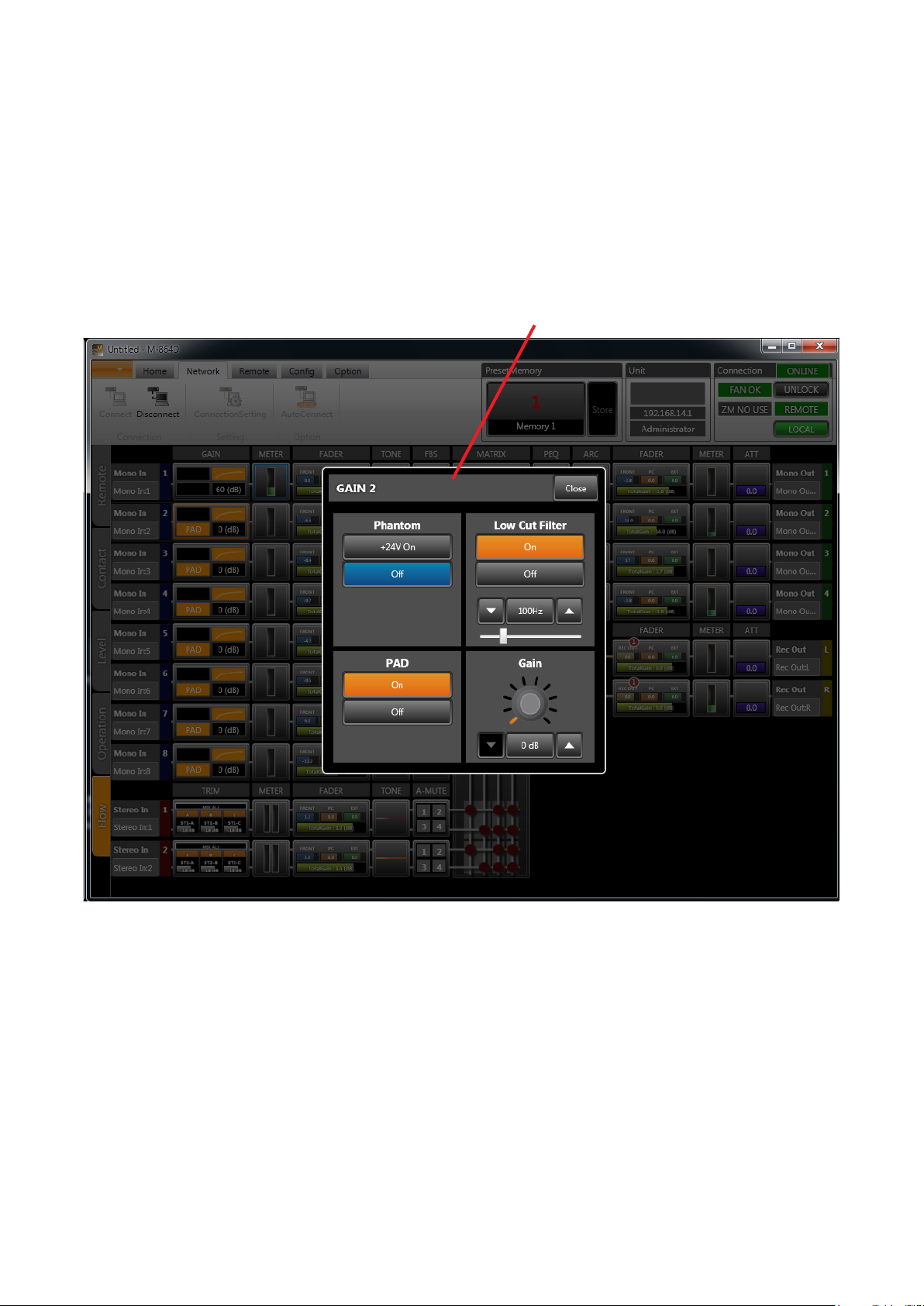
7.1. Gain
This monaural input function box is used to set phantom power ON/OFF, PAD, low-cut lter and gain.
(1) Phantom power ON
(2) Phantom power OFF
(3) PAD ON
(4) PAD OFF
1. Phantom Power ON
Clicking this button sets the phantom power to ON,
causing the display to be shown in orange.
2. Phantom Power OFF
Clicking this button sets the phantom power to
OFF, causing the display to be shown in blue.
3. PAD ON
Clicking this box sets PAD to ON, causing the
display to be shown in orange. Set PAD to ON
when the corresponding channel’s monaural input
signal is a line level.
4. PAD OFF
Clicking this button sets PAD to OFF, causing the
display to be shown in black. Set PAD to OFF when
connecting a microphone to the corresponding
channel.
(5) Low-cut lter ON
(6) Low-cut lter OFF
(7) Low-cut lter’s frequency control
(8) Gain control
The cutoff frequency can be set by moving the
lower slider to the left or right. Move the slider to
the right to increase the cutoff frequency and to the
left to reduce it.
8. Gain Control
Used to set the gains.
Clicking on the downward-pointing triangle reduces
the cutoff frequency.
Clicking on the upward-pointing triangle increases
the cutoff frequency.
Clicking the frequency indication in the center
opens the dialog for entering the gain.
5. Low-Cut Filter ON
Clicking this button sets the low-cut lter to ON,
causing the display to be shown in orange.
6. Low-Cut Filter OFF
Clicking this button sets the low-cut lter to OFF,
causing the display to be shown in blue.
7. Low-Cut Filter’s Frequency Control
Sets the low-cut lter’s cutoff frequency.
Clicking on the downward-pointing triangle at left
reduces the cutoff frequency.
Clicking on the upward-pointing triangle at right
increases the cutoff frequency.
Clicking the frequency indication in the center
opens the dialog for entering the cutoff frequency.
Gain settings can be changed by dragging the
vicinity of the GUI’s center of the volume control.
Note
Variable gain ranges can be changed with the PAD
ON/OFF settings:
PAD ON: 0 to +18 dB
PAD OFF: +15 to +60 dB
47
Page 48

7.2. Trim
This is a function box for the stereo input function and is used to set the MIX ALL/SELECT mode, ON/OFF
statuses and names of each of input sources A, B and C, and gains.
(1) MIX ALL Mode
(2) SELECT Mode
Control Details for sources A, B and C
(3) A/B/C Source Control
1. MIX /ALL Mode
Clicking this button sets it to MIX ALL mode and
illuminates the display in orange. In MIX ALL
mode, the signal levels of Sources A, B and C are
adjusted with their respective trim gains, and then
mixed together.
Note
Input sources set to OFF in the “ON/OFF” settings
are not mixed.
2. SELECT Mode
Clicking this button sets it to SELECT mode and
illuminates the display in orange. In SELECT mode,
only one of Sources A, B and C is selectable.
(4) ON/OFF
(5) Name
(6) Trim Control
5. Name
Sets the names of input sources A, B and C. Each
name can be entered if clicked.
6. Trim Control
Sets the trim gain, which can be reduced by clicking
on the downward-pointing triangle and increased
by clicking on the upward-pointing triangle.
Clicking the gain indication in the center opens the
diagram for trim gain entry.
3. A/B/C Source Control
Sets Source A/B/C’s “ON/OFF,” “Name” and “Trim
Gain.”
4. ON/OFF
Sets the ON/OFF status of input sources A, B and
C. In the SELECT mode, only one of Sources A,
B, and C can be set to ON. Also, all three sources
cannot be simultaneously set to OFF (one must
always be ON).
The display is illuminated in orange if set to ON,
and in blue if set to OFF.
Trim gain settings can be changed by dragging the
vicinity of the GUI’s center of the volume control.
48
Page 49

7.3. Fader
This function box is for monaural input, stereo input, monaural output and recording output.
• Fader Type and Name
Fa d er Type Fader Name Remarks
FRONT FADER FRONT fader Fader on the unit’s front panel
PC VOL. PC VOL. fader PC software and external control protocol
EXT VOL. EXT VOL. fader ZM Remote controller and contact control
REC OUT VOL. REC OUT VOL. fader Volume control on the unit’s front panel
• Disabling the Fader
To disable gain changes made with fader operation, set the corresponding fader to “Disable” in the Fader
Settings on p. 99.
(Faders set to “Disable” are xed at 0 dB gain.)
Faders set to “Disable” are not displayed.
[Monaural input, Stereo input and Monaural output]
(1) Channel name
(2) Channel ON/OFF button
(3) Fader box total gain
(4) FRONT fader gain
(5) PC VOL. gain
(6) FRONT fader
Note
This fader is displayed in
online mode as shown at
right when the fader is set
to “Enable” in the Fader
Settings on p. 99.
(7) PC VOL. grouping number
(8) EXT VOL. grouping number
(9) EXT VOL. bypass settings
(10) EXT VOL. gain
(11) EXT VOL. fader
(12) PC VOL. fader
49
Page 50

[Recording output]
(1) Channel name
(2) Channel ON/OFF button
(3) Fader box total gain
(7) PC VOL. grouping number
(13) REC OUT VOL. grouping
number
(14) REC OUT VOL. gain
(5) PC VOL. gain
(15) REC OUT VOL. fader
1. Channel Name
Displays the channel name.
Clicking the channel name indicator allows its
name to be changed.
2. Channel ON/OFF button
Switches the channel to ON or OFF.
This setting interlocks with the grouping setting for
EXT VOL.
3. Fader Box Total Gain
Displays total gain values set with the FRONT
fader, PC VOL. and EXT VOL. faders for monaural
and stereo inputs and monaural output.
Displays total gain values set with the REC OUT
VOL., PC VOL. and EXT VOL. faders for recording
output. The green bar at left indicates the total gain
value.
(8) EXT VOL. grouping number
(9) EXT VOL. bypass settings
(10) EXT VOL. gain
(11) EXT VOL. fader
(12) PC VOL. fader
6. FRONT Fader
Displays the fader position corresponding to the
gain value set with the unit’s FRONT fader gain (4)
only while in online mode. (In this case, the fader is
displayed but cannot be operated.)
Even in online mode, however, the fader is not
displayed when set to “Disable” in the Fader
Settings on p. 99.
The total gain (3) in ofine mode is obtained as 0
dB of the FRONT fader gain.
7. PC VOL. Grouping Number
Displays the PC VOL. fader’s grouping number.
The color corresponding to the group is displayed
to the right of the grouping number. Clicking this
button opens the dialog for grouping number
selection.
4. FRONT Fader gain
Displays the gain value set with the FRONT fader
(6). The gain value cannot be changed.
5. PC VOL. gain
Displays the gain value set with the PC VOL. fader
in dB. Clicking this button displays the dialog for
gain settings, allowing gains to be entered using
numerical values. This PC VOL. gain is interlocked
with the PC VOL. fader (12).
After selecting the group to be set, click the [OK]
button, and the setting is enabled.
50
Page 51

8. EXT VOL. Grouping Number
Displays the EXT VOL. fader’s grouping number.
The color corresponding to the group is displayed
to the right of the grouping number. Clicking this
button opens the dialog for grouping number
selection.
After selecting the group to be set, click the “OK”
button, and the setting is enabled.
12. PC VOL. Fader
Displays the fader position corresponding to the
gain value set with the PC VOL. gain (5). This
fader is interlocked with the PC VOL. gain (5) and
can be operated by dragging the fader knob.
13. REC OUT VOL. Grouping Number
Displays the REC OUT VOL. fader’s grouping
number. The color corresponding to the group
is displayed to the right of the grouping number.
Clicking this button opens the dialog for grouping
number selection.
9. EXT VOL. Bypass Settings
Displays the EXT VOL. fader’s bypass settings.
The indication is displayed in orange if set to ON,
and in blue if set to OFF.
Notes
• If Bypass is set to ON, gains set with the EXT
VOL. fader are not enabled in the fader box total
gain.
• Each Preset Memory allows the volume control
operation by ZM Remote controller or contact
input to be bypassed.
10. EXT VOL. Gain
Displays the gain value set with the EXT VOL.
(11) in dB. Clicking this button displays the dialog
for gain settings, allowing gains to be entered
using numerical values. This EXT VOL. gain is
interlocked with the EXT VOL. fader (11).
11. EXT VOL. Fader
Displays the fader position corresponding to the
gain value set with the EXT VOL. gain (10). This
fader is interlocked with the EXT VOL. gain (10)
and can be operated by dragging the fader knob.
After selecting the group to be set, click the “OK”
button, and the setting is enabled.
14. REC OUT VOL. Gain
Displays the gain value set with the REC OUT
VOL. (15) in dB. Clicking this button displays
the dialog for gain settings, allowing gains to be
entered using numerical values. This REC OUT
VOL. gain is interlocked with the REC OUT VOL.
fader (15).
15. REC OUT VOL. Fader
The fader setting is interlocked with the unit’s
recording output volume setting.
Displays the fader position corresponding to the
gain value set with the REC OUT VOL. gain (14).
This fader is interlocked with the REC OUT VOL.
gain (14) and can be operated by dragging the
fader knob.
51
Page 52

7.4. Tone
This function box for monaural and stereo inputs is used to set tone using the BASS, MID and TREBLE lters
accessible at 3 points.
(1) Filter control eld
(2) BASS lter point (3) MID lter point
(4) TREBLE lter point
(5) Filter point initial value
BASS control TREBLE control
MID control
(6) Lock button (7) Resolution button (8) Q indicator button
BASS control
(9) Frequency
control
(10) Gain control
1. Filter Control Field
Displays tone frequency characteristics in a graph.
By dragging the BASS, MID and TREBLE lter
points, each lter can be set.
2. BASS Filter Point
The blue circle within the lter control eld is a
BASS lter point. Frequencies and gains can be
changed by dragging the lter point. The BASS
lter is a low shelving lter.
3. MID Filter Point
The yellow circle within the lter control eld is
a MID lter point. Frequencies and gains can be
changed by dragging the lter point. Clicking the
white circle displayed to the left of the lter point
and dragging it up and down allows the MID lter
point’s Q value to be changed. The MID lter is a
parametric equalizer.
MID control
TREBLE control
(9) Frequency
control
(10) Gain control
(11) Q control
4. TREBLE Filter Point
The green circle within the lter control eld is a
TREBLE lter point. Frequencies and gains can be
changed by dragging the lter point. The TREBLE
lter is a high shelving parametric equalizer.
5. Filter point initial value (Right-click menu)
The setting value of each point can be initialized
by selecting the “Point Clear” from the menu
displayed when you right-click on the lter point
on a graph.
(9) Frequency
control
(10) Gain control
52
Page 53

6. Lock Button
Used for locking frequencies or gains when
dragging the BASS, MID or TREBLE lter points.
Clicking “Freq. Unlock” at left changes the
indication, locking the frequency.
If the frequency is locked, it becomes
unchangeable even if the lter point is dragged
left and right.
Clicking the same button again restores the
previous display and releases the lock. Clicking
“Gain Unlock” at right changes the indication,
locking the gain.
If the gain is locked, it becomes unchangeable
even if the lter point is dragged up and down.
Clicking the same button again restores the
previous display and releases the lock.
Both the frequency and gain can be locked.
Note
Frequencies and gains can only be locked for
the lter point operation. The frequency and gain
controls can be used to change settings even
while in locked mode.
The following 3 display methods are available:
(1) Numerical indication
Q values are indicated by means of a numerical
gure.
(2) Oct/band fractional indication
The value of the octave bandwidth corresponding
to the Q value is indicated by a fractional gure.
(3) Oct/band numerical indication
The value of the octave bandwidth corresponding
to the displayed Q value is indicated by a
numerical gure.
Example: When the Q value is 4.318
Numerical indication: 0.333
Oct/band fractional indication: 1/3 oct/band
Oct/band numerical indication:
9. Frequency Control
Used to set the individual frequencies of the
BASS, MID and TREBLE lters.
The downward pointing triangle button reduces
the frequency, and the upward pointing triangle
button increases the frequency.
Clicking the frequency indication in the center
opens the dialog for entering the frequency.
4.318 oct/band
7. Resolution Button
Used to set the resolution for frequency and gain
settings.
If “Freq. : Low” at left is clicked, the indication
changes and the frequency settings resolution is
set to “High.”
Clicking the same button again restores the
previous display and sets the resolution for
frequency settings to “Low.” Resolution for
frequency settings is as follows:
Low: 1/24 octave
High: 3-digit signicant gure
If “Amplitude: Low” at right is clicked, the indication
changes and the resolution for gain settings is set
to “High.”
10. G ain Cont rol
Used to set the individual gains of the BASS, MID
and TREBLE lters.
The downward pointing triangle button reduces
the gain, and the upward pointing triangle button
increases the gain.
Clicking the gain indication in the center opens a
dialog for entering the gain.
11. Q Control
Used to set the MID lter’s Q.
The downward pointing triangle button reduces Q,
and the upward pointing triangle button increases Q.
Clicking the Q indication in the center opens the
dialog for selecting Q.
Clicking the same button again restores the
previous display and sets the resolution for gain
settings to “Low.” Resolution for gain settings is
as follows:
Low: 0.5 dB
High: 0.1 dB
8. Q Indication Button
Used to switch the display method for the MID
lter’s Q.
53
Page 54

7.5. FBS (Feedback Suppressor Function)
This function box is for monaural input and is used to set the FBS lter.
(1) Filter control eld (2) Minimum frequency
adjustment button
(3) Maximum frequency
adjustment button
(4) Maximum amplitude
adjustment button
(5) Dynamic mode button
(6) Clear dynamic button
(7) Filter point control
(8) Filter point guard
button
(13) Minimum amplitude
adjustment button
(9) Lock button (11) Scale setting button (12) Q indication button
1. Filter Control Field
Displays the FBS frequency characteristics when
in graph display mode. In table display mode, the
FBS lter’s parameter ON/OFF and guard settings
are displayed in table formats.
To set the display mode, click the Graph/Table
Display Selector Button (10).
(Table format display)
Select the lter point to be set in the Filter Point
Control (7) menu.
In graph display mode, protected lter point
gains and Q parameters can be changed by drag
operation.
2. Minimum Frequency Adjustment Button
Sets the minimum frequency for the graph display.
(10) Graph/Table display
selector button
(Sets the left edge of a graph.)
The leftward pointing triangle button decreases
the frequency, and the rightward pointing triangle
button increases the frequency.
3. Maximum Frequency Adjustment Button
Sets the maximum frequency for the graph display.
(Sets the right edge of a graph.)
The leftward pointing triangle button decreases
the frequency, and the rightward pointing triangle
button increases the frequency.
4. Maximum Amplitude Adjustment Button
Sets the maximum amplitude for the graph display.
(Sets the upper limit of the graph.)
The downward pointing triangle button reduces the
amplitude and the upward pointing triangle button
increases the amplitude.
5. Dynamic Mode Button
Sets the dynamic FBS function ON/OFF.
Notes
• ON: When acoustic feedback is detected, the
FBS lter’s parameter is automatically
enabled, dynamically suppressing the
feedback.
• OFF: No automatic settings are performed for
the FBS lter’s parameter, and dynamic
feedback suppression is not enabled.
• Switching the button from ON to OFF clears the
lter that has been automatically created when
acoustic feedback was detected in dynamic mode.
54
Page 55

6. Clear Dynamic Button
Clears the set parameters of all FBS lter points
that have been automatically created when
acoustic feedback was detected in dynamic
mode.
Notes
• Protected lter points are not cleared.
• This button can be operated only while in online
mode.
10. Graph/Table Display Selector Button
Switches the display of the lter control eld.
“Graph”: The button is displayed in gray and
the lter control eld is placed in graph
display mode.
“Table”: The button is displayed in orange and
the lter control eld is placed in table
display mode.
7. Filter Point Control
Displays the selected FBS lter point’s
parameters. At the protected point, gains and Q
values can be changed.
Filter No.
Frequency
Gain
Q
Note
The FBS lter’s parameter is automatically set
if the FBS function is set to ON. Parameters of
unprotected points cannot be changed.
8. Filter Point Guard Button
Sets the guard function for the selected FBS lter
point.
The indication is displayed in yellow if “Yes” is
selected, and in gray if “No” is selected.
Notes
• For the FBS lter set to “Yes,” the lter
parameter is not updated even if the dynamic
FBS function has been set to ON with the
Dynamic Mode button. Select “Yes” when not
wishing to change the lter parameter because,
for example, it is desirable to x the frequency
for feedback suppression.
• For the FBS lter set to “No,” the lter parameter
may be changed when feedback is newly
detected. Gains and Q values can be changed
for the guarded lter point.
9. Lock Button
Used to enable or disable the locking of gains
when dragging lter points.
Clicking “Gain Unlock” changes the indication,
locking the gain.
If the gain is locked, it becomes unchangeable
even if the lter point is dragged up and down.
Clicking the same button again restores the
previous display and releases the lock.
Note
Gains can only be locked for the lter point
operation. The gain control can be used to change
settings even while in locked mode.
11. Scale Setting Button
Clicking this button while the lter control eld
is in graph display mode displays the dialog for
setting the graph’s scale.
A. Minimum frequency settings
C. Maximum amplitude
settings
D. Minimum amplitude
settings
E. Step settings
B. Maximum frequency settings
A. Minimum Frequency Settings
Sets the minimum frequency for the graph
display (i.e. sets the left edge of the graph).
The downward pointing triangle button
decreases the frequency and the upward
pointing triangle button increases the
frequency.
Clicking the frequency indication in the center
opens the dialog for frequency entry.
B. Maximum Frequency Settings
Sets the maximum frequency for the graph
display (i.e. sets the right edge of the graph).
The downward pointing triangle button
decreases the frequency and the upward
pointing triangle button increases the frequency.
Clicking the frequency indication in the center
opens the dialog for frequency entry.
C. Maximum Amplitude Settings
Sets the maximum amplitude for the graph
display (i.e. sets the upper limit of the graph).
The downward pointing triangle button
decreases the amplitude and the upward
pointing triangle button increases the amplitude.
The amplitude varies by the value set in the
55
Page 56

Step settings each time the button is clicked.
Clicking the amplitude indication in the center
opens the dialog for amplitude entry.
D. Minimum Amplitude Settings
Sets the minimum amplitude for the graph
display (i.e. sets the lower limit of the graph).
The downward pointing triangle button
decreases the amplitude and the upward
pointing triangle button increases the amplitude.
The amplitude varies by values set in the Step
settings each time the button is clicked.
Clicking the amplitude indication in the center
opens the dialog for amplitude entry.
Q values are indicated by a numerical gure.
(2) Oct/band fractional indication
The value of the octave bandwidth corresponding
to the Q value is indicated by a fractional gure.
(3) Oct/band numerical indication
The value of the octave bandwidth corresponding
to the displayed Q value is indicated by a
numerical gure.
Example: When the Q value is 69.249
Numerical indication: 0.021
Oct/band fractional indication:
1/48 o ct/ban d
Oct/band numerical indication:
69.249 oct/band
E. Step Settings
Sets the spacing between amplitude scale
lines in the graph display.
Set step values are also used as spacing for
the amplitude set with the triangle buttons in
the maximum and minimum amplitude settings
of Items (C) and (D) above.
12. Q Indication Button
Used to switch the FBS lter’s Q indication.
The following 3 methods are available:
(1) Numerical indication
Tips
• The FBS lter stored in the Preset Memory cannot be recalled even when changing the Preset Memory while
the FBS function is ON. The FBS lter currently in operation remains active and unchanged.
• The FBS lter point for which guard function is not set to "Yes" will be cleared when the M-864D is powered
on.
13. Minimum Amplitude Adjustment Button
Sets the minimum amplitude for the graph display.
(Sets the lower limit of the graph.)
The downward pointing triangle button reduces
the amplitude and the upward pointing triangle
button increases the amplitude.
56
Page 57

7.6. Auto-Mute
This function box for stereo input is used to set the Auto-Mute function* for each of monaural output channels 1 – 4.
* This function attenuates the stereo input level when the monaural input signal level exceeds the threshold.
All monaural inputs 1 – 8 become triggers that attenuate the stereo input level. Threshold can be set individually
for each monaural input.
Attenuation and hold time can be set individually for stereo inputs 1 and 2.
(Application example)
Connection of a microphone to the monaural input, and a background music (BGM) device to the stereo input:
The Auto-Mute function automatically reduces the BGM level during microphone announcements to make it
easier to hear the announcement.
For more information on the Auto-Mute function, see p. 118 , “Automatic mute function” in the Glossary.
(2) Threshold settings indication(1) Threshold control
(3) Monaural channel selector button
(4) Assignment display
(5) Mute control (8) ON/OFF settings button
(7) Stereo channel selector button
(6) Mute settings display
1. Threshold Control
Sets the start threshold of the monaural input that
triggers the Auto-Mute. Monaural inputs subject to
this setting are those selected with the Channel
Selector button.
The start threshold can be set by dragging the
threshold point (gray circle) up and down.
Start threshold
End thresholdThreshold point
The start threshold set here is reected in the
“Threshold Settings” indication.
Note on Start threshold level and end threshold
level:
If the monaural input level set to become a trigger
exceeds the start threshold, the Auto-Mute function
is enabled and the stereo input gain is attenuated.
If the monaural input level drops below the end
threshold, the Auto-Mute is disabled and, after a
hold time passes, the stereo input gain is gradually
restored.
Since hysteresis (the difference between start and
end thresholds) is xed at 12 dB, the end threshold
is automatically set to a value 12 dB below the start
threshold.
The orange line in the threshold control indicates
the start threshold, and the gray line indicates the
end threshold.
57
Page 58

2. Threshold Settings Indication
Indicates the start threshold of the monaural input
that becomes the Auto-Mute trigger.
For more information on the Auto-Mute function,
see p. 118, “Automatic mute function” in the
Glossary.
3. Monaural Channel Selector Button
Selects the monaural input channel for which the
start threshold is set.
Clicking the button selects the corresponding
channel, turning that button’s color to orange.
4. Assignment Display
Monaural input matrix assignment is displayed by
a black circle.
The monaural input working as the mute trigger
is displayed with a ashing point(s) only while in
online mode.
Note
To perform assignment settings, see p. 59,
“Matrix.”
5. Mute Control
Sets the Auto-Mute reduction level (gain
attenuation) and hold time.
Stereo inputs subject to this setting are those
selected with the Stereo Channel Selector button
(7).
The attenuation level can be set by dragging a
reduction level point (gray circle at left) up and
down.
The hold time can be set by dragging a hold time
point (gray circle at right) left and right.
6. Mute Settings Display
Displays the Auto-Mute attenuation level (gain
attenuation) and hold time.
7. Stereo Channel Selector Button
Used to select the stereo input channel for which
the attenuation level (gain attenuation) and hold
time are set.
Clicking the button selects the corresponding
channel, turning that button’s color to orange.
8. ON/OFF Settings Button
Used to set the Auto-Mute function ON/OFF.
Notes
• ON/OFF settings here have nothing to do with
output assignment.
Use the matrix function boxes for output signal
assignment (see the next item “Matrix”).
• Since the L (left) channel of both stereo inputs
1 and 2 cannot be assigned to Output 2 in the
matrix stereo assignment settings, the ON/OFF
button is not displayed at an Output 2 matrix
point. Similarly, since the R (right) channel
cannot be assigned to Output 1 in the matrix
stereo assignment settings, the ON/OFF button
is not displayed at an Output 1 matrix point.
• Auto-Mute ON/OFF settings are interlocked with
both L and R stereo channels.
Hold time pointReduction level point
The reduction level and hold time set here are
reected in the Mute Settings display.
Note on Auto-Mute operation:
If the monaural input level set as the trigger
exceeds the start threshold, the Auto-Mute function
is enabled and the stereo input gain gradually
attenuates to the reduction level. The stereo input
gain’s fade-out time varies depending on the
reduction level setting. The fade-out time slope
(length) is xed, and set at 0.65 seconds when the
reduction level is −30 dB.
When the monaural input level drops below the end
threshold, the Auto-Mute is disabled and, after a
hold time passes, the stereo input gain is gradually
restored.
The stereo input gain’s fade-in time varies
depending on the reduction level settings. The
fade-in time slope (length) is xed, and set to 1.3
seconds when the attenuation level is −30 dB.
58
Page 59

7.7. Matrix
This function box is used for monaural input, stereo input, monaural output and recording output signal routing.
Notes
• The Matrix Function box is displayed in the Flow view, and not displayed in the Operation view.
• The Matrix Function box is interlocked with the Assign Function box.
[Assignment display only]
(1) Input channel display
(3) Mono assign selector button (4) Recording output channel display
(2) Monaural output channel display
(5) Display selector button
(6) ON/OFF button
[Assignment and crosspoint gain display]
(1) Input channel display
(2) Monaural output channel display
(5) Display selector button
(7) Crosspoint gain control
(6) ON/OFF button
(3) Mono assign selector button (4) Recording output channel display
59
Page 60

1. Input Channel Display
Displays information (name and number) for each
monaural and stereo input channel.
2. Monaural Output Channel Display
Displays information (name and number) for each
monaural output channel.
3. Mono Assign Selector Button
Stereo input can be assigned to monaural Outputs
1 – 4.
Usually, the Stereo Assign mode is used for
assignment to monaural Outputs 1 and 2, however
the Mono Assign mode can also be used.
For assignment to monaural Outputs 3 and 4,
always use the Mono Assign mode.
The Mono Assign selector button is used to
switch the method of assigning the stereo input to
monaural Outputs 1 and 2.
•StereoAssign
In this mode, the “L” (left) stereo input is
assigned to monaural Output 1, and “R”
(right) to monaural Output 2.
•MonoAssign
In this mode, “L” (left) and “R” (right) of the
stereo input are mixed and assigned to each
of monaural outputs 1 and 2.
the center opens the dialog for gain entry.
Notes
• The stereo input’s crosspoint gain is interlocked
with the “L” (left) and “R” (right).
• The recording output’s crosspoint gain is xed at
0 dB.
4. Recording Output Channel Display
Displays information (name and number) for each
recording output channel.
5. Display Selector Button
Switches the display mode between “Assign only”
and “with Level.”
6. ON/OFF Button
Used to select Assign ON or OFF.
For monaural and stereo input assignments, set the
point at which the left side “Input Channel” display
crosses the upper “Monaural Output Channel”
display.
For recording output assignment, set the point
at which the upper “Monaural Output Channel”
display crosses the right side “Recording Output
Channel” display.
Assignment is turned ON or OFF by clicking, and
displayed in yellow (orange for recording output
assignment) if set to ON, or black if set to OFF.
Reducing the crosspoint gain makes the yellow
color depth darker. (Since the recording output’s
crosspoint gain is always set at 0dB, the orange
color’s depth does not change.)
Note
The assign ON/OFF settings for both “L” (left) and
“R” (right) stereo input channels are interlocked.
7. Crosspoint Gain Control
Used to set the crosspoint gain.
Use the downward pointing triangle button to
reduce the gain, and the upward pointing button
to increase the gain. Clicking the gain indication in
60
Page 61

7.8. Assign
This function box is used for monaural input, stereo input and recording output signal routing.
Notes
• The Assign Function box is displayed in the Operation view, and not displayed in the Flow view.
• The Assign Function box is interlocked with the Matrix Function box.
[Monaural Input and Stereo Input Assignments]
(1) Input channel display
(2) Output channel No.
(5) Crosspoint gain control
(3) ON/OFF button
(4) Crosspoint gain display
[Recording Output Assignment]
(2) Output channel No. (3) ON/OFF button
1. Input Channel Display
Displays the monaural or stereo input channel.
2. Output Channel Number
Monaural or stereo input assignment:
The channel number to which the input is assigned
is displayed.
Recording output assignment:
The assigned monaural output channel number is
displayed.
3. ON/OFF Button
Click to select assignment ON or OFF. This button
is displayed in orange when set to ON, and blue
when OFF.
Notes
• ON/OFF settings are interlocked with the Matrix
Function box.
• Two different modes can be used to assign the
stereo input to monaural output 1 or 2: Mono
Assign mode and Stereo Assign mode.
• MonoAssignmode
Stereo inputs L (left) and R (right) are mixed and
assigned.
• StereoAssignmode
Stereo input “L” (left) is assigned to Monaural
Output 1 and stereo input “R” (right) is assigned
to Monaural Output 2.
Use the Matrix Function box’s Mono assign
selector button (see p. 59) to change the
assign mode.
(Only the Mono Assign mode can be used to
assign the stereo input to Monaural Outputs
3 and 4, and the monaural output to recording
output.)
61
Page 62

4. Crosspoint Gain Display
A yellow triangle indicates the gain by varying in size depending on the crosspoint gain set with the Crosspoint
Gain Control (5).
5. Crosspoint Gain Control
Used to set the crosspoint gain.
Use the downward pointing triangle button to reduce the gain, and the upward pointing button to increase the
gain. Clicking the gain indication in the center opens the dialog for gain entry.
Dragging in the vicinity of the center of the volume control allows gain settings to be changed.
Notes
• The stereo input’s crosspoint gain is interlocked with “L” (left) or “R” (right).
• The recording output’s crosspoint gain is xed at 0 dB.
62
Page 63

7.9. PEQ
This function box for monaural outputs is used to compensate for each output’s frequency characteristics with
a 5-point parametric equalizer.
(1) Filter control eld (2) Filter point , (3) Filter point initial value
Filter point control
Filter point No.
(4) Frequency control
(5) Gain control
(6) Q control
(7) ON/OFF button
(8) Lock button (9) Resolution button (10) Q indicator button(11) Grouping button
1. Filter Control Field
PEQ frequency characteristics are displayed by a
graph.
Each lter can be set by dragging its corresponding
lter point.
2. Filter Point
Filter points are indicated by ve yellow circles
within the lter control eld. Frequencies and gains
can be changed by dragging the lter points.
3. Filter point initial value (Right-click menu)
The setting value of each point can be initialized by
selecting the “Point Clear” from the menu displayed
when you right-click on the lter point on a graph.
4. Frequency Control
Sets each lter point’s frequency.
The downward pointing triangle button decreases
the frequency and the upward pointing triangle
button increases the frequency.
Clicking the frequency indication in the center
opens the dialog for frequency entry.
5. Gain Control
Sets each lter point’s gain.
The downward pointing triangle button reduces
the gain and the upward pointing triangle button
increases the gain.
Clicking the gain indication in the center opens the
dialog for gain entry.
6. Q Control
Sets each lter point’s Q.
The downward pointing triangle button reduces Q
and the upward pointing triangle button increases
Q. Clicking the Q indication in the center opens the
dialog for Q selection.
63
Page 64

7. ON/OFF Button
Sets each lter point to ON or OFF.
ON: Filter is enabled (orange display).
OFF: Filter is disabled (blue display).
The lter is bypassed if set to OFF.
8. Lock Button
Used to enable or disable the locking of
frequencies or gains when dragging lter points.
Clicking “Freq. Unlock” at left changes the
indication, locking the frequency.
If the frequency is locked, it becomes
unchangeable even if the lter point is dragged
left and right.
Clicking the same button again restores the
previous display and releases the lock. Clicking
“Gain Unlock” at right changes the indication,
locking the gain.
If the gain is locked, it becomes unchangeable
even if the lter point is dragged up and down
Clicking the same button again restores the
previous display and releases the lock.
Both the frequency and gain can be locked.
Note
Frequencies and gains can only be locked for
the lter point operation. The frequency and gain
controls can be used to change settings even
while in locked mode.
9. Resolution Button
Used to set the resolution for frequency and gain
settings.
Clicking the same button again restores the
previous display and sets the for gain settings
resolution to “Low.” The gain settings resolution
is as follows:
Low: 0.5 dB
High: 0.1 dB
10. Q Indicator Button
Used to switch the Q display method of each lter
point.
The following 3 different display methods are
available:
(1) Numerical indication
Q values are indicated by a numerical gure.
(2) Oct/band fractional indication
The value of the octave bandwidth
corresponding to the Q value is indicated by a
fractional gure.
(3) Oct/band numerical indication
The value of the octave bandwidth
corresponding to the Q value is indicated by a
numerical gure.
Example: When the Q value is 4.318
Numerical indication: 0.333
Oct/band fractional indication:
1/3 oct/band
Oct/band numerical indication:
4.318 oct/band
11. Grouping But ton
Clicking this button opens the dialog for selecting
the grouping number.
If “Freq. : Low” at left is clicked, the indication
changes and the frequency settings resolution is
set to “High.”
Clicking the same button again restores the
previous display and sets the frequency settings
resolution to “Low.” The frequency settings
resolution is as follows:
Low: 1/24 octave
High: 3-digit signicant gure
If “Gain: Low” at right is clicked, the indication
changes and the gain settings resolution is set to
“High.”
64
Page 65

7.10. ARC
This function box for monaural output is used to set the Automatic Resonance Control (ARC) function for each
of output channels 1 – 4.
(1) Filter point selection button
(3) Minimum frequency adjustment button
(4) Filter control eld
(2) Maximum frequency adjustment button
(5) Detail setting panel
(6) Maximum amplitude
adjustment button
(7) Minimum amplitude
adjustment button
(8) Lock button
(9) Graph/table display selection button
(10) Scale settings button
(11) Q indication button
1. Filter Point Selection Button
Click to select one of 12 lters.
In graph display mode, the selected lter’s lter
point is highlighted.
In table display mode, the selected lter’s row is
highlighted.
When the detail setting panel is set to “Individual
Settings,” the selected lter’s parameter is
displayed.
2. Maximum Frequency Adjustment Button
Sets the maximum frequency in graph display
mode (sets the right edge of a graph).
The leftward pointing triangle button decreases
the frequency and the rightward pointing triangle
button increases the frequency.
(12) Grouping button
4. Filter Control Field
ARC frequency characteristics are displayed by a
graph in graph display mode.
In table display mode, the ARC lter parameters
and ON/OFF settings are displayed in table form.
To set the display mode, click the Graph/table
Display Selection Button (9).
(Table format display)
3. Minimum Frequency Adjustment Button
Sets the minimum frequency in graph display mode
(sets the left edge of a graph).
The leftward pointing triangle button decreases
the frequency and the rightward pointing triangle
button increases the frequency.
65
Page 66

5. Detail Settings Panel
Individual Settings, Global Settings and
Measurement Settings can be performed through
tab selection.
(1) Individual Settings
Filter point No.
A. Frequency control
D. ON/OFF Button
Used to set each lter point to ON or OFF.
ON: Filter is enabled (orange display).
OFF: Filter is disabled (blue display).
The lter is bypassed if set to OFF.
(2) Global Settings
B. Gain control
C. Q control
D. ON/OFF button
E. Default button
A. Frequency Control
Sets each lter point’s frequency.
The downward pointing triangle button
decreases the frequency and the upward
pointing triangle button increases the
frequency.
Clicking the frequency indication in the
center opens the dialog for frequency entry.
B. Gain Control
Sets each lter point’s gain.
The downward pointing triangle button
reduces the gain and the upward pointing
triangle increases the gain. Clicking the gain
indication in the center opens the dialog for
gain entry.
C. Q Control
Sets each lter point’s Q.
The downward pointing triangle button
reduces Q and the upward pointing triangle
button increases Q.
Clicking the Q indication in the center opens
the dialog for Q selection.
A. Global gain control
B. All On/Off button
C. All Default button
A. Global Gain Control
Used to nely adjust the strength of
automatically created lters.
To increase the lter strength, click the
lower [Aggressive] button, and the upper
[Moderate] button to moderate it. To return
the lter to standard strength, click the
[Normal] button in the center. The strength
can also be nely adjusted with the use of a
slider at right.
B. All On/Off Button
Selects ON or OFF for all 12 lters.
ON: Filter is enabled. (orange display)
OFF: Filter is disabled. (blue display)
The lter is bypassed if set to OFF.
C. All Default Button
Returns all 12 lters to the parameters
created by ARC measurement.
Tips
• The ARC box retains the following 2
different settings: lter data created by
ARC measurement and actual operation
lter data manually adjusted. The former
data can be initialized by the Initialize
button shown on the next page.
• On the graph display, the lter data created
at measurement is indicated by a dotted
line and the actual operation lter data is
indicated by a solid line.
66
Page 67

(3) Measurement Settings
A. Measurement start
frequency settings button
B. Measurement stop
frequency settings button
C. Sweep time settings
button
D. Output level
compensation button
E. Measurement button
F. Initialize button
A. Measurement Start Frequency Settings
Button
Sets the measurement start frequency.
The downward pointing triangle button
decreases the frequency and the upward
pointing triangle button increases the
frequency.
B. Measurement Stop Frequency Settings
Button
Sets the measurement stop frequency.
The downward pointing triangle button
decreases the frequency and the upward
pointing triangle button increases the
frequency.
C. Sweep Time Settings Button
Sets the frequency sweep time from the start
of measurement till its end.
The downward pointing triangle button
decreases the time and the upward pointing
triangle button increases the time.
D. Output Level Compensation Button
Sets the compensation value of the
measuring signal’s output level.
The downward pointing triangle button
decreases the output level and the upward
pointing triangle button increases the output
level.
E. Measurement Button
This button can be operated only while in
online mode.
The ARC Measurement dialog is displayed.
Measurement
start button
6. Maximum Amplitude Button
Sets the maximum amplitude for the graph
display. (Sets the upper limit of the graph.)
The downward pointing triangle button reduces
the amplitude and the upward pointing triangle
button increases the amplitude.
7. Minimum Amplitude Button
Sets the minimum amplitude in graph display
mode (sets the lower limit of the graph).
The downward pointing triangle button decreases
amplitude and the upward pointing triangle button
increases amplitude.
8. Lock Button
Used to enable or disable the locking of
frequencies or gains when dragging lter points.
Clicking “Freq. Unlock” at left changes the
indication, locking the frequency.
If the frequency is locked, it cannot be changed,
even if the lter point is dragged left or right.
Clicking the same button again restores the
previous display and releases the lock. Clicking
“Gain Unlock” at right changes the indication,
locking the gain.
If the gain is locked, it cannot be changed even if
the lter point is dragged up or down.
Clicking the same button again restores the
previous display and releases the lock.
Both the frequency and gain can be locked.
Note
Frequencies and gains can only be locked by
operating the lter point. The frequency and gain
controls can be used to change settings even
while in Lock mode.
9. Graph/Table Display Selection Button
Switches the display of the lter control eld.
Graph: The button is displayed in gray and the
lter control eld is placed in graph display
mode.
Table: The button is displayed in orange and the
lter control eld is placed in table display
mode.
Measurement begins if the Measurement
start button is clicked.
F. Initialize Button
This button can be operated only while in
online mode.
Initializes the lter that has been created by
ARC measurement.
67
Page 68

10. Scale Setting Button
Clicking this button while the lter control eld
is in graph display mode displays the dialog for
setting the graph’s scale.
A. Minimum frequency settings
C. Maximum amplitude settings
B. Maximum frequency settings
A. Minimum Frequency Settings
Sets the minimum frequency for graph display
(i.e. sets the left edge of the graph).
The downward pointing triangle button
decreases the frequency and the upward
pointing triangle button increases the
frequency.
Clicking the frequency indication in the center
opens the dialog for frequency entry.
B. Maximum Frequency Settings
Sets the maximum frequency for the graph
display (i.e. sets the right edge of the graph).
The downward pointing triangle button
decreases the frequency and the upward
pointing triangle button increases the
frequency.
Clicking the frequency indication in the center
opens the dialog for frequency entry.
C. Maximum Amplitude Settings
Sets the maximum amplitude for the graph
display (i.e. sets the upper limit of the graph).
The downward pointing triangle button
decreases the amplitude and the upward
pointing triangle button increases the
amplitude. The amplitude varies by values set
in the Step settings each time the button is
clicked.
Clicking the amplitude indication in the center
opens the dialog for amplitude entry.
D. Minimum amplitude
settings
E. Step settings
D. Minimum Amplitude Settings
Sets the minimum amplitude for the graph
display (i.e. sets the lower limit of the graph).
The downward pointing triangle button
decreases the amplitude and the upward
pointing triangle button increases the
amplitude. The amplitude varies by values set
in the Step settings each time the button is
clicked.
Clicking the amplitude indication in the center
opens the dialog for amplitude entry.
E. Step Settings
Sets the spacing between amplitude scale
lines in the graph display.
Set step values are also used as spacing for
the amplitude set with the triangle buttons in
the maximum and minimum amplitude settings
of Items (C) and (D) above.
11. Q Indication Button
Used to switch the lter point’s Q indication
method.
The following three methods are available:
(1) Numerical indication
Q values are indicated by a numerical gure.
(2) Oct/band fractional indication
The value of the octave bandwidth
corresponding to the Q value is indicated by a
fractional value.
(3) Oct/band numerical indication
The value of the octave bandwidth
corresponding to the Q value is indicated by a
numerical gure.
Example: When the Q value is 4.318
Numerical indication: 4.318
Oct/band fractional indication:
1/3 oct/band
Oct/band numerical indication:
0.333 oct/band
12. Grouping Button
Sets grouping within the ARC box.
On ARC measurement completion, the measurement
target ARC boxes are automatically grouped,
cancelling already-set grouping on any of these
boxes, if there was. Actual operation lter data,
measurement parameters, and the lter data
created by ARC measurement are interlocked
among the grouped ARC boxes.
68
Page 69

[ARC operating procedures]
Before Starting Operation:
Set the external equipment sound volume and other settings to actual usage conditions to ensure that sound
can be amplied at an appropriate volume level.
Note
Connect the microphone to MONO INPUT 1.
Connect the unit to a PC to allow communications between the two.
Measurements for all ARC boxes connected to the MONO OUTPUTs to which the MONO INPUT 1 is assigned
are performed simultaneously.
Refer to the separate M-864D instruction manual for details about ARC measurement such as an installation
example of the measuring microphone.
Step 1. In the Matrix setting screen, assign the MONO INPUT 1 to the MONO OUTPUT connecting the target
ARC box for measurement.
(Example when ARC 1, 2, and 4 are targeted for ARC settings)
Step 2. Click the ARC box targeted for the ARC setting to open the pop-up sub-view.
Step 3. Make the following measurement settings on the Detail Settings
panel: Measurement start and stop frequencies, Sweep time, and
Output level compensation.
Step 4. Install the measuring microphone.
Step 5. Click the Measurement button on the Detail Settings panel to display
the ARC measurement dialog. Then, click the Measurement start
button.
The ARC measurement is started.
The progress status of the measurement is displayed on the screen
as shown in the gure below:
Measurement
Start button
Stop button
3
5
Note: To stop before the operation is complete, click the [Stop] button.
Upon measurement completion, the lter parameter is automatically set, displaying the frequency
characteristics in the lter control eld.
The measurement target ARC boxes are automatically grouped.
If any of the ARC boxes had been grouped before measurement, this group setting is automatically
canceled at ARC measurement.
69
Page 70

Step 6. Adjust the lter.
6-1. Adjust the lter strength.
The automatically created lter is set to a standard level of strength. To adjust it, use the Global Gain
Control button located on the global settings panel of the Detail Settings panel. (See p. 66.)
Click the lower [Aggressive] button to make the lter relatively stronger, or the upper [Moderate] button
to modulate its strength.
To return the lter to standard strength, click the [Normal] button in the center. Filter strength can also
be nely adjusted with the slider.
6-2. Manually changing the lter.
Values can be changed by dragging the lter point in the lter control eld or by using the Frequency
or Gain controls on the individual settings panel of the Detail Setting panel.
Tip
To cancel the manually changed parameter and revert it to the automatically created parameter, click
the Default button on the Individual Settings panel appearing through the Point tab to cancel individual
points, and click the All Default button on the Global Settings panel appearing through the All Point tab
to cancel all points simultaneously.
[When canceling the set ARC data]
The ARC box handles the following 3 types of data:
(1) Actual operation lter data
(2) Filter data created by measurement
(3) Measurement parameters (measurement start and stop frequencies, sweep time, and output level
compensation)
The above data can be cancelled by the following methods.
• To cancel the above data (2), click the [Initialize] button on the Detailed Settings
panel appearing through the Measure tab only while in online mode.
• To cancel the above data (1) and (3), select “Clear” from the menu appearing by
right-clicking on the ARC box. (For default settings, see p. 126.)
7.11. Attenuator
This function box for monaural and recording outputs is used to set the attenuation of each output.
(1) Gain Display
(2) Fader
1. Gain Display
Indicates the attenuator gain.
2. Fader
Sets the attenuator gain. A fader knob is displayed
in the position corresponding to the gain value.
Drag the fader knob to operate the fader. The
attenuation varies in 6 dB steps (xed).
70
Page 71

8. STATUS VIEW
The Status view is located in the upper right section of the Main screen.
The Status view is comprised of Memory view, Unit view and Connection view.
Memory View Unit View Connection View
8.1. Memory View
Displays the name and the number of the currently selected Preset Memory (see p. 102). If “Store” is also
clicked, data can be written in the Preset Memory. Clicking the Preset Memory name and number displays the
Memory List panel.
[Memory list panel]
A total of 16 buttons, each of which shows a Preset Memory name and crossfade time (see p. 102), are
displayed. The currently selected Preset Memory button is displayed in orange.
“Change safe layers” are displayed in the Memory view and on the Memory list panel when the change safe
function is enabled.
[Memory view] (when the change safe function is enabled)
Change safe layers
[Memory list panel] (when the change safe function is enabled)
Change safe layers
71
Page 72

8.1.1. Changing the Preset Memory
Select the Preset Memory button to be changed and click the [Change] button.
Example: Changing to Preset Memory 6
Step 2. Click the [Change] button.
Step 1. Select Preset Memory 6.
8.1.2. Storing edit contents in the Preset Memory
To store the edit content, select the Preset Memory button in which the contents are to be stored, then click the
[Store] button.
Example: Storing in Preset Memory 6
When storing in the Preset Memory
being edited, the contents can also be
stored by clicking the Memory view’s
[Store] button.
Step 2. Click the [Store] button.
Step 1. Select Preset Memory 6.
Click the [Store] button.
72
Page 73

8.1.3. Deleting edit contents
To discard the contents in edit, click the [Trash] button.
After the contents are deleted, the previously stored pre-edit parameters are loaded.
Note: Once the edit contents have been deleted, they cannot be restored.
Click the [Trash] button.
For each Preset Memory’s name and crossfade time settings, see p. 102, “Preset Memory Settings” in the
Conguration settings.
73
Page 74

8.2. Unit View
The unit’s name and IP address are displayed.
(1) Unit Name
(2) Unit IP address
(3) User Level
1. Unit Name
Displays the unit’s name.
2. Unit IP Address
The unit’s IP address is displayed. For the unit IP
address, see p. 76, “Connection Settings” in the
“Communication Settings.”
8.3. Connection View
This view displays the unit’s status.
(1) Unit communication connection
status indication
(2) Unit cooling fan status indication
(3) ZM Remote Controller status
indication
1. Unit Communication Connection Status Indication
The status of the unit’s communication connection
is displayed.
: Not connected (Ofine mode)
: Connection in progress (Online mode)
2. Unit Cooling Fan Status Indication
The status of the unit’s cooling fan is displayed.
: Normal
: Failure
3. ZM Remote Controller Status Indication
The ZM Remote Controller’s connection status is
displayed.
: No settings
: Normal
: Failure
4. Unit’s System Lock Button
The status of the lock button on the unit’s front
panel is displayed.
: Locked
: Unlocked
3. User Level
The user level is displayed. For the user level, see
p. 113, “User Level and Prohibition Settings.”
(4) Unit’s system lock button
(5) Remote control status
indication
(6) Local button
5. Remote Control Status Indication
Displays the status that any operation by a PC,
external control, or ZM Remote controller is
enabled.
It is enabled whenever the PC is online with the
unit.
: Remote
6. Local Button
The unit’s local status is displayed. This button
is used to switch between local and non-local
statuses while in Online mode.
: Local
: Unlocal
[Local status]
The unit’s front panel knobs and other controls are
enabled and their values are valid.
[Unlocal status]
The unit’s front panel knobs and other controls are
disabled and their values are invalid. Faders are
set to 0 dB gain (bypassed mode).
Note
The “Cannot conrm” indication is displayed while
in Ofine mode.
74
Page 75

9. COMMUNICATION SETTINGS
9.1. Connections between a PC and the Unit
Connect a PC and the M-864D to a switching hub using LAN straight cables individually.
PC with the M-864D PC
Software installed
M-864D
LAN connection
terminal
Switching hub
Category 5 or higher shielded
twisted pair straight cable for LAN
(with RJ45 connectors)
9.2. Method to Enable Communications between the PC and the Unit
Step 1. Perform network settings by selecting [Network Connection Settings] from the menu.
(See p. 76, “Connection Settings.”)
Step 2. Make Communications by selecting [Network Connect] from the menu.
(See p. 79, “Communications.”)
75
Page 76

9.3. Connection Settings
Perform settings needed to communicate with the units in this section.
Network settings can be made.
Step 1. Select [Network Connection Setting] from the menu.
Network settings of the units found on the network are displayed.
The table below shows the factory preset settings for each unit.
IP address 19 2 .16 8 .14.1
Subnet mask 255.255.255.0
Default gateway 0.0.0.0
2
4 5
3
6
If no unit was detected:
Install the undetected unit within the reach of broadcast packet.
Communications may be interrupted when the PC is rewall-protected.
If a unit’s IP address is duplicated or inappropriate network setting has been performed, such device is displayed
in the Unconnectable units list.
• To change the unit’s IP address setting, advance to Step 2.
• When transmitting the settings data changed in Step 2 to the unit, advance to Step 3.
• When changing the PC’s network settings, change them from the Windows Control Panel. PC network setting
cannot be changed using the M-864D PC software.
• When connecting to the unit via a router, network settings are not displayed on this screen. The unit network
settings cannot be changed. Connect such unit to a LAN and perform the network settings in advance.
• If a unit needs to be connected via a router, advance to Step 4 to add it.
• If the unit that should not be communicated with is displayed in the list, advance to Step 5 to delete it from the
list.
• Advance to Step 6 when all the units to be connected are displayed in “Connectable units” list.
• When the PC has two or more IP addresses, select the unit and IP address to be communicated with from
the PC’s IP address.
76
Page 77

Step 2. Change the unit’s network setting.
Select the unit for which you want to change the network setting, then click the [Modify IP setting]
button. The IP Setting screen is displayed.
Set the IP address, then click the [OK] button.
Step 3. Transmit changed setting data to the unit.
Clicking the [Send the setting] button transmits the IP settings to the corresponding unit and network
setting for the unit is changed.
4 5
Step 4. Add the unit to be connected via a router in a list. Clicking the [Add] button displays the [Add target unit]
screen. Enter the IP address of the added unit and click the [OK] button.
Note
Network setting for the unit to be connected via a router cannot be changed using the method described
in Step 2.
If you need to change the network setting, connect such unit to a LAN and change the network setting
in advance.
4
77
Page 78

Step 5. Delete the unit from the list.
Select the unit to be deleted, then click the[Delete] button.
The selected unit is deleted from the list.
Step 6 Click the[Next] button, then the Firmware version check screen is displayed.
7
• When the rmware version of the M-864D is older than that the M-864D software supports, the
M-864D is displayed in the Uncontrollable units list.
• If a unit that does not need to be controlled is displayed, advance to Step 7 to delete it from the list.
• When updating rmware, advance to Step 8 .
• If all units to be controlled are shown in the Controllable units list, advance to Step 9.
Step 7. Delete the unit from the list.
Select the unit to be deleted, then click the [Delete] button.
The selected unit is deleted from the list.
Step 8. Update the rmware.
Select the unit from the Uncontrollable units list and click the [Firmware update] button.
Firmware update starts.
The unit is moved to and displayed in the Controllable units list after the rmware update is complete.
Notes
• Updating the rmware version from Ver. 1.0.x to Ver. 2.0.x causes the unit to reactivate twice. (“x”
represents a revision number.)
Never switch off the M-864D unit’s power during rmware update.
• The setting data is retained even after rmware update.
8
10
Step 9. Select the unit(s) from the Controllable units list.
Step 10. Click the[Finish] button.
Setting is complete.
78
Page 79

9.4. Communications
Connect to the unit displayed “Connectable units” eld in the Unit’s IP setting screen.
Step 1. Select [Network Connect] from the menu.
While the screen below is displayed, the target unit designated with the connection settings are being
detected.
Note
If no units on the network have been set for the connection settings, the Unit’s IP Setting screen is
displayed.
Perform network settings in the same manner as in the steps on p. 76, “Connection Settings.”
On completion of network settings, the units listed in “Connectable units” eld start being connected.
79
Page 80

Step 2. Match both setting data of the PC and the unit if not identical.
To enable communications between the PC and the unit, both setting data must be the same.
If data is different between the PC and the target unit, the Communication screen appears indicating
“Different” in the Status column during connection.
Designate the transfer direction “PC >> Unit” or “Unit >> PC,” and click the [Update] button. Then, all
unmatched setting data is simultaneously transferred in the designated direction.
Step 3. Select [Network
This terminates communications between a PC and the unit.
Disconnect] from the menu.
80
Page 81

10. REMOTE SETTINGS
Set contact input and output functions, ZM Remote Controller control functions, and the external control port.
10.1. Remote Function Overview
10.1.1. Contact input and output functions
Various functions can be allocated to the contact input and output by changing the settings on the contact input
and contact output setting screens. To permit external control by connected equipment, short terminals 1 – 8
to the C terminal. For example, when terminals 1 – 8 have been allocated to Preset Memory Nos. 1 – 8 in the
contact input settings, shorting individual terminals to the C terminal allows Preset Memory Nos. 1 – 8 to be
called up.
(1) Contact input functions
None (unused)
Channel On/Off
EXT VOL. Up/Down
ST Line Source Select
Preset Memory Load
Remote Command
(2) Contact output functions
Break
Make
Channel On/Off
ST Line Source Select
Preset Memory Load
Contact Through Out
Remote Switched Out
Fader Tally
For details, see p. 82, “Contact Input Settings” and p. 84, “Contact Output Settings.”
10.1.2. ZM Remote Controller control functions
The ZM Remote Controller Settings screen permits various functions to be allocated to the remote controller.
ZM Remote Controller control button functions
None (unused)
Channel On/Off
EXT VOL. Gain
ST Line Source Select
Matrix Crosspoint Assign
Matrix Crosspoint Gain
Preset Memory Load
Remote Switched Out
Remote Command
EXT VOL. GainCS(H) (ZM-9014 only)
Matrix Crosspoint GainCS(E) (ZM-9014 only)
ZM Remote Controller volume control functions
None (unused)
EXT VOL. Gain
Matrix Crosspoint Gain
EXT VOL. GainCS(H) (ZM-9014 only)
Matrix Crosspoint GainCS(E) (ZM-9014 only)
For details, see p. 87, “ZM Remote Controller Settings.”
81
Page 82

10.1.3. External control port
Set the port number of the external control port (the port to be externally controlled from the external device).
For details, see p. 91, “External Control Port Setting.”
10.1.4. External control command send function
Performs command control to the external devices via TCP/IP
Commands can be sent to the external devices by means of a contact input or the control signal from the ZM
Remote controller that works as a trigger.
For details, see p. 92, “External Control Command Send setting.”
10.2. Contact Input Settings
Select [Remote Input] from the Menu view to display the Contact Input Settings screen.
This setting item is related to the system.
(1) Terminal No. (3) Parameter
(2) Function (4) Control
1. Terminal No.
Displays the contact input terminal number (1 – 8).
2. Function
Displays the function assigned to the terminal.
Clicking the button allows the function to be
selected.
Select “None” when assigning no functions to the
terminal.
3. Parameter
Displays parameter settings corresponding to the
function assigned in the “Function” Column.
Clicking the button allows the parameters to be
selected.
Note that some assigned functions have no
parameters.
4. Control
Displays control settings if “Channel On/Off” is
assigned on the “Function” menu. Click the button
to select either “Make” or “Pulse.”
(5) Position
(6) Channel/Contact
5. Position
Displays the position settings corresponding to the
function assigned in the “Function” Column.
Click on the button to select the position.
Mono In: Monaural input
Stereo In: Stereo input
Mono Out: Monaural output
Rec Out: Recording output
Note that some assigned functions have no
position settings.
6. Channel/Contact
Displays the channel selection settings
corresponding to the function assigned in the
“Function” Column.
Clicking the button allows the channel to be
selected.
When Position is “Mono In”: 1 – 8
When Position is “Stereo In”: 1 – 2
When Position is “Mono Out”: 1 – 4
When Position is “Rec Out”: L, R
Note that some assigned functions have no channel
selection settings.
82
Page 83

•FunctionSettings
The following functions can be set for each terminal:
[Channel On/Off]
Switches the selected channels On or Off.
Use the “Position” and “Channel/Contact” columns to select the channel.
The On/Off control method differs depending on the “Control” column settings.
Make: Channels are set to On when their terminals are shorted to the C terminal, and to Off when opened.
Pulse: Channels alternate between On and Off when their terminals are shorted to the C terminal.
[EXT VOL. Up/Down]
Used to increase or reduce the EXT VOL. fader gain for the selected channels. Use the “Position” and “Channel/
Contact” columns to select the channels. Whenever a terminal is shorted to the C terminal, its gain increases
or decreases by 1 dB. If the button is held down and the terminal is kept closed, the gain continues to increase
or decrease.
Notes
• This function is allocated to any 2 terminals in consecutive order.
Gain “Up” is allocated to the terminal with the lower number, and gain “Down” is allocated to the terminal with
the higher number. For example, if this function is selected at Terminal 4, it is automatically allocated to both
Terminals 4 and 5, giving Terminal 4 the “Up” function and Terminal 5 the “Down” function.
The “Up” function cannot be assigned to Terminal 8. If this function is selected for Terminal 7, Terminal 7 will
be designated as “Up” and Terminal 8 as “Down.”
• This gain UP/DOWN function cannot be allocated to any channel that has its EXT VOL. fader disabled.
For EXT VOL. fader Enable/Disable settings, see p. 99, “Fader Settings” section in the Conguration
settings.
[ST Line Source Select]
Used to select the stereo input source (connected to Terminals A, B and C of each stereo input).
Stereo Input 1 and Stereo Input 2 are selected in the “Channel/Contact” column. Use the “Parameter” column
to select Source A, B or C.
Operation differs depending on the stereo input trim mode settings.
MIX ALL mode: The ON/OFF settings of Terminals A, B and C set in the “Parameter” column are switched.
Sources are toggled between ON and OFF each time a connected terminal is shorted to the
C terminal.
SELECT mode: The input source set in the “Parameter” column is selected and set to ON when its
corresponding terminal is shorted to the C terminal.
When Sources A, B and C are assigned to multiple terminals, the last shorted terminal takes
precedence.
[Preset Memory Load]
Accesses the Preset Memory.
Set the Preset Memory (1 – 16) to be called up in the “Parameter” column.
The Preset Memory set in the “Parameter” column is accessed when its corresponding terminal is shorted to
the C terminal.
If different Preset Memories are assigned to multiple terminals, the last shorted terminal takes precedence.
[Remote Command]
Assign the command number for the External control command send function to the terminals.
Shorting the corresponding terminal to the C terminal sends the specied command.
When no function is to be assigned to a terminal, select “None” in the “Function” column.
83
Page 84

10.3. Contact Output Settings
Select [Remote Output] from the Menu view to display the Contact Output Settings screen.
This setting item is related to the system.
(1) Terminal No. (3) Parameter
(2) Function (4) Control
1. Terminal No.
Displays the contact output terminal number (1 –
8).
2. Function
Displays the function assigned to the terminal.
Clicking the button permits the function to be
selected.
Select “Break” when assigning no function to the
terminal.
(5) Position
(6) Channel/Contact
5. Position
Displays the position settings that correspond to
the function assigned in the “Function” column.
Click on the button to select the position.
Mono In: Monaural input
Stereo In: Stereo input
Mono Out: Monaural output
Rec Out: Recording output
Note that some assigned functions have no
position settings.
3. Parameters
Displays the parameter settings that correspond to
the function assigned in the “Function” column.
Clicking the button allows the parameters to be
selected.
Note that some assigned functions have no
parameters.
4. Control
Displays control settings if “Remote Switched
Out” or “Fader Tally” is assigned in the “Function”
column.
When “Remote Switched Out” is set, clicking the
button permits the selection of either “Momentary”
or “Latch.”
When “Fader Tally” is set, clicking the button
permits the selection of either “Make” or “Pulse.”
6. Channel/Contact
Displays channel selection settings that correspond
to the function assigned in the “Function” column.
Click on the button to select the channel:.
When Position is “Mono In”: 1 – 8
When Position is “Stereo In”: 1 – 2
When Position is “Mono Out”: 1 – 4
When Position is “Rec Out”: L, R
Note that some assigned functions have no channel
selection settings.
84
Page 85

•FunctionSettings
The following functions can be set for each terminal:
[Break]
The terminal remains open.
[Make]
The terminal remains closed (shorted to the C terminal).
[Channel On/Off]
Provides a Make or Break contact for the specied channel On/Off.
Select the channel in the “Position” and “Channel/Contact” columns.
The terminal is closed (Make contact) when the channel is On, and open (Break contact) when the channel is
Off.
[ST Line Source Select]
Outputs a Make or Break contact depending on the selection status of the specied channel’s stereo input
source.
Set the selection status to be output in the “Parameter” column.
Select the channel in the “Channel/Contact” column.
Operation differs depending on the stereo input trim mode settings.
(1) MIX ALL mode
Provides a Make or Break contact according to ON/OFF status of Terminals A, B or C set in the “Parameter”
column.
The terminal is closed when ON and is opened when OFF.
(2) SELECT mode
Outputs a Make or Break contact depending on the selection status of A, B or C set in the “Parameter”
Column. The terminal is closed when selected and remains open when not selected.
[Preset Memory Load]
Outputs a Make or Break contact depending on the selection status of the specied Preset Memory.
Set the desired Preset Memory number in the “Parameter” column.
The terminal is closed if the Preset Memory set in the “Parameter” column is selected, and opened if another
Preset Memory is selected.
[Contact Through Out]
Outputs a Make or Break contact depending on the selection status of the specied Preset Memory.
Set the desired contact input terminal in the “Parameters” column.
If the contact input terminal set in the “Parameters” column is closed, the contact output terminal is also closed.
If the contact input terminal is opened, then the contact output terminal is also opened.
85
Page 86

[Remote Switched Out]
Outputs a Make or Break contact by ON/OFF operation control from the ZM Remote Controller or other
externally connected device.
Both momentary type and latch type are available for the terminal control method. Select either type in the
“Control” Column.
Below is the operation diagram for each type of control method.
• Momentary type
ON/OFF operation of
ZM Remote Controller’s
function button
Contact output state
Over 100 ms
• Latch type
ON/OFF operation of
ZM Remote Controller’s
function button
Contact output state
ON
OFF OFF
Over 100 ms
Make
Beak Beak
ON ON ON ON
OFF
Make
OFF OFF OFF
Beak Beak
ON
Make
Make
Note
To output a contact for control by the ZM Remote Controller, perform the following operations on the ZM
Remote Controller Settings screen (shown on p. 87):
Step 1. Allocate “Remote Switched Out” to the ZM Remote Controller’s “Function” button.
Step 2. Set the contact output terminal number.
[Fader Tally]
Outputs a Make or Break contact depending on whether the FRONT fader’s gain value exceeds (ON) the
threshold level or not (OFF). The threshold level corresponds to the fader scale “1” (approximately –60 dB).
Terminal control differs depending on the “Control” column setting.
Make: The terminal is closed when in ON status, and is opened when in OFF status.
Pulse: A shorting pulse is generated between the corresponding terminal and the C terminal when the
status changes from ON to OFF.
Tip
When no function is allocated to the terminal, select “Break” with the corresponding “Function” column button.
86
Page 87

10.4. ZM Remote Controller Settings
Selecting [Remote Setting] from the Menu view displays the ZM Remote Controller Settings screen.
This setting item is related to the system.
(1) ZM Remote Controller
selection button
(2) Setting screen
(3) Address indication
(4) Type
(5) Button or volume control No.
(6) Name
1. ZM Remote Controller Selection Button
Displays both the address and ZM Remote
Controller model number.
If a ZM Remote Controller is not connected or not
set, the “None” indication is displayed.
Clicking this button displays the settings of the ZM
Remote Controller with the selected address on
the “Settings” screen. The selected address button
is displayed with an orange frame.
(7) Function button (8) Parameter 1 button
(9) Parameter 2 button
2. Settings Screen
The ZM Remote Controller set for each address
and its settings are displayed.
3. Address Indication
The selected address is displayed.
87
Page 88

4. Typ e
The ZM Remote Controller’s type is displayed.
5. Button or Volume Control No.
The ZM Remote Controller’s button number or
volume control number is displayed.
: None
: ZM-9011
: ZM-9012
: ZM-9013
: ZM-9014
6. Name
The names of the ZM Remote Controller’s buttons
and volume control are displayed.
Clicking this button permits the name to be
entered.
7. Function Button
Functions assigned to the ZM Remote Controller’s
buttons and volume control are displayed.
Functions can be selected by clicking the Function
column button.
When no functions are assigned to the button,
select “None.”
8. Parameter 1 Button
Parameter settings corresponding to the function
assigned in the Function column are displayed.
Clicking the Parameter 1 button allows the
rst parameter to be selected. Note that some
assigned functions have no parameters.
9. Parameter 2 Button
Parameter settings corresponding to the function
assigned in the Function column are displayed.
Clicking the Parameter 2 Button allows the
second parameter to be selected. Note that some
assigned functions have no parameters.
10.4.1. Assigning button functions
The following functions can be set for each button on the ZM Remote Controller:
[Channel On/Off]
Switches the specied channel On or Off.
Select the channel in the “Channel Kind” column of Parameter 1 and the “Channel No.” column of Parameter 2.
Parameter 1 Parameter 2
Channel Kind Channel No.
Mono In 1 – 8
Stereo In 1 – 2
Mono Out 1 – 4
Rec Out L, R
Channels toggle between On and Off with each depression of the ZM Remote Controller’s button.
88
Page 89

[EXT VOL. Gain]
Used to increase or reduce the EXT VOL. fader gain for the selected channels. Use the “Channel Kind” column
of Parameter 1 and the “Channel No.” column of Parameter 2 to select the channel. The gain increases or
decreases by 1 dB with each depression of the ZM Remote Controller’s button. If the button is held down and
the terminal is kept closed, the gain continues to increase or decrease.
Notes
• This function is allocated to 2 buttons in consecutive order.
Gain “Up” is allocated to the button with the lower number, and gain “Down” is allocated to the button with
the higher number. For example, if this function is selected for Button 2, it is automatically allocated to both
Buttons 2 and 3, giving Button 2 the “Up” function and Button 3 the “Down” function.
For this reason, it is impossible to allocate the “UP” function to Button 4 of the ZM-9011 and ZM-9014 Remote
Controllers and to Button 8 of the ZM-9013 Remote Controller.
• This function does not work even if allocated to any channel that has its EXT VOL. fader disabled.
[ST Line Source Select]
Selects stereo input sources (A, B and C).
Select stereo input 1 or 2 in the “Channel No.” column of Parameter 1. For A, B and C channel selection, use
the “Line Source” column of Parameter 2.
Operation differs depending on the stereo input trim mode settings.
(1) MIX ALL mode
The ON and OFF settings of Terminals A, B and C set in the “Line Source” column are switched. Sources
are toggled between ON and OFF each time the ZM Remote Controller’s corresponding button is pressed.
(2) SELECT mode
Input source A, B or C set in the “Line Source” column is selected and set to ON when its corresponding
ZM Remote Controller’s button is pressed. When sources A, B and C are assigned to multiple buttons, the
last selected button takes precedence.
[Matrix Crosspoint Assign]
The assign ON/OFF settings of the specied matrix crosspoint are switched. Select the crosspoint in the “Input
Channel” column of Parameter 1 and in the “Output Channel” column of Parameter 2.
Parameter 1 Parameter 2
Input channel Output channel
Mono In 1 – 8
Stereo In 1 – 2
Assignment status alternates between ON and OFF with each depression of the ZM Remote Controller’s
corresponding button.
[Matrix Crosspoint Gain]
Used to increase or reduce the specied matrix crosspoint’s gain. Select the crosspoint in the “Input Channel”
column of Parameter 1 and in the “Output Channel” column of Parameter 2.
The gain increases or decreases by 1 dB with each depression of the ZM Remote Controller’s button. If the
button is held down and the terminal is kept closed, the gain continues to increase or decrease.
Mono Out 1 – 4
Note
This function is allocated to any 2 buttons in consecutive order.
Gain “Up” is allocated to the button with the lower number, and gain “Down” is allocated to the button with the
higher number. For example, if this function is selected for Button 2, it is automatically allocated to both Buttons
2 and 3, giving Button 2 the “Up” function and Button 3 the “Down” function.
For this reason, the “UP” function cannot be assigned to Button 4 of the ZM-9011 and ZM-9014 Remote
Controllers, and to Button 8 of the ZM-9013 Remote Controller.
89
Page 90

[Preset Memory Load]
Calls up Preset Memory.
Set the Preset Memory (1 – 16) to be called up in the ”Preset No.” column of Parameter 1. If the ZM Remote
Controller’s button is pressed, the Preset Memory set in the “Preset Number” column is called up. If different
Preset Memories are assigned to multiple buttons, the last pressed button takes precedence.
[Remote Switched Out]
Controls the M-864D’s contact output terminals.
Set the control output terminal number (1 – 8) to be operated in the “Contact Out No.” column of Parameter 1.
Notes
• If the selected contact output terminal is not assigned the “Remote Switched Out” function, it will not operate.
The contact input terminal of the device to be controlled must also be set to the “Remote Contact Input”
function.
• The control method of the selected contact output terminal differs depending on its “Control” column settings.
Make: The terminal is closed when the button is pressed and opened when the button is released.
Pulse: A shorting pulse is generated between the corresponding terminal and the C terminal with each
depression of the button.
[Remote Command]
Assign the command number for the External control command send function to the terminals.
Press the ZM Remote controller’s button to send the specied command.
[EXT VOL. GainCS (Channel Select)] (function provided only with the ZM-9014)
Select the channel to be operated with the volume control knob.
Change the channel to be operated with the volume control knob by pressing the ZM Remote controller’s button.
Notes
• Assign the same function to the volume control knob.
• This function does not work even if allocated to the channel for which the EXT VOL. fader is disabled.
[Matrix Crosspoint GainCS (Crosspoint Select)] (function provided only with the ZM-9014)
Select the Matrix crosspoint to be operated with the volume control knob.
Change the Matrix crosspoint to be operated with the volume control knob by pressing the ZM Remote
controller’s button.
Note: Assign the same function to the volume control knob.
[When no functions are assigned to the button]
Select “None” with the Function button.
90
Page 91

10.4.2. Assigning functions to the volume control
The following functions can be set for the Volume Control on the ZM Remote Controller.
[EXT VOL. Gain]
Increases or decreases the specied channel’s EXT VOL. fader gain.
To select the channel, perform settings in the “Channel Kind” column of Parameter 1 and in the “Channel No.”
column of Parameter 2.
Note: This function does not work even if allocated to channels for which the EXT VOL. fader is disabled.
[Matrix Crosspoint Gain]
Increases or reduces the specied matrix crosspoint gain.
To select the crosspoint, perform settings in the “Input Channel” column of Parameter 1 and in the “Output
Channel” column of Parameter 2.
Parameter 1 Parameter 2
Input channel Output channel
Mono In 1 – 8
Stereo In 1 – 2
[EXT VOL. GainCS (Channel Select)] (function provided only with the ZM-9014)
Mono Out 1 – 4
Increases or decreases the gain of the specied channel’s EXT VOL. fader.
The channel can be selected with the button to which the same function is assigned.
[Matrix Crosspoint GainCS (Crosspoint Select)] (function provided only with the ZM-9014)
Increases or decreases the gain of the specied Matrix crosspoint.
The crosspoint can be selected with the button to which the same function is assigned.
[When no functions are assigned to the Volume Control]
Select “None” with the Function button.
10.5. External Control Port Setting
Select [Remote Port Setting] from the Menu view to display the Port Setting screen.
This setting item is related to the system.
(1) External control port
(2) Meter port
1. External control port
Set the port number for receiving the external
control commands from the external control device
such as AMX.
Note: For details about the external control, read
the "M-864D External Control Protocol"
included in the supplied CD.
The latest version is made available on the
TOA product data download site
(http://www.toa-products.com/international/).
2. Meter port setting
Indicates the port number for sending level meter
data.
The meter port number is automatically set to
External control port number plus 1.
91
Page 92

10.6. External Control Command Send Setting
Select [Remote Remote Command] from the Menu view to display the External Command Setting screen.
This setting item is related to the system.
The set command can be sent by assigning it to a contact input or ZM Remote controller.
[External control command send setting screen]
3 1 2
Step 1. Select the Targets tab, and perform settings related to the control target device.
(See p. 94)
Step 2. Select the Parameters tab, and perform settings related to the parameters.
(See p. 95.)
Step 3. Select the Commands tab, and perform settings related to the commands.
(See p. 93.)
92
Page 93

[External Command Setting screen (when the Commands tab is selected)]
Command selection area
Setting items
(1) Command name
(2) Target selection
(3) Time interval
(4) Parameter selection
Create the external control commands.
Up to 32 commands can be created.
Select the command to be set from the Command selection area, then perform settings for each item shown
below.
1. Command name
Enter the command name.
Use up to 20 alphanumeric characters for input.
2. Target selection
Select the control target device from the pull-down
menu.
Perform settings related to the control target device
on the screen displayed when the targets tab is
selected (see p. 94).
3. Time interval
Select the send interval from the pull-down menu.
(Setting range: 0 to 3000 ms, 100 ms steps)
4. Parameter selection (1 through 12)
Select the Parameter name from the pull-down
menu.
Perform settings related to the parameters on
the screen displayed when the Parameters tab is
selected (see p. 95).
93
Page 94

[External Command Setting screen (when the Targets tab is selected)]
(1) Target name (2) IP address (3) Port number
Perform settings related to the target (control target device).
Up to 4 targets can be registered.
1. Target name
Enter the control target device name.
Use up to 20 alphanumeric characters for input.
2. IP address
Enter the control target device’s IP address.
3. Port number
Enter the port number to connect to the control
target device.
94
Page 95

[External Command Setting screen (when the Parameters tab is selected)]
(1) Parameter name (2) Data
(3) Length (bytes)
Set the parameters to be used in the command settings.
Up to 120 parameters can be registered.
1. Parameter name
Enter the parameter name.
Use up to 20 alphanumeric characters for input.
2. Data
Enter the data in hexadecimal notation (2 digits of
0 to 9 and A to F).
ASCII characters cannot be used for entry.
To enter the data name, convert ASCII character to
character code.
Each parameter can be registered using up to 20
bytes in 1-byte units.
3. Length (bytes)
Set the parameter length to be used.
95
Page 96

10.6.1. TCP/IP communication specifications
• Assign the M-864D as a TCP client.
• The TCP port performs connection and disconnection every time a command is sent.
Note
This function cannot control all external control devices.
Check the functional operation on the actual device.
10.6.2. Command configuration
Parameter 1 Interval Parameter 2 • • • Interval Parameter 12
(Maximum)
10.6.3. Command sequence
1. Connection to the target (Session starts.)
2. Command data send
3. Disconnection from the target (Session ends.)
96
Page 97

11. CONFIGURATION SETTINGS
This chapter covers the setting of the unit’s name, the names of its inputs and outputs, the enabling/disabling
of its faders, unit operation lock, and Preset Memory names.
[Unit Name Settings]
The names of the unit, its monaural and stereo inputs, monaural and recording outputs, and stereo input
sources can all be set on a single screen.
Note
Stereo input source names can also be set at the corresponding stereo input channel’s trim box.
[Fader Settings]
Each fader can be independently enabled or disabled.
Faders set to Disable are xed at 0 dB gain.
[Unit Lock (System Lock) Setting]
Unit operation can be locked.
If locked, parameters cannot be changed by way of the front panel faders or switches.
The unit’s system lock function can be used to prevent changes in parameter settings through either misoperation
or tampering.
Faders and switches can be selected by type to be locked or unlocked.
Use the unit’s System lock key or the System lock button located in the Connection view to enable the lock
function.
[Preset Memory Settings]
The following items can be set: Preset Memory name, cross-fade time, Preset Memory number load when
power is ON, and Preset Memory interlock.
97
Page 98

11.1. Unit Name Settings
Select [Cong Name] from the Menu view to display the Name Settings screen.
(1) Unit name
(3) ST Line source name (4) Stereo input channel name
1. Unit Name
The unit’s name is displayed.
Click on the button to enter the unit’s name.
2. Monaural Input Channel Name
The name of each monaural input channel is
displayed.
Click on the corresponding button to enter the
channel name.
3. ST Line Source Name
The name of each stereo input source is displayed.
Click on the corresponding button to enter the input
source name.
(2) Monaural input channel name
4. Stereo Input Channel Name
The name of each stereo input channel is displayed.
Click on the corresponding button to enter the
channel name.
5. Monaural Output Channel Name
The name of each monaural output channel is
displayed.
Click on the corresponding button to enter the
channel name.
6. Recording Output Channel Name
The name of each recording output is displayed.
Click on the corresponding button to enter the
channel name.
(5) Monaural output channel name
(6) Recording output channel name
Tip: Up to 20 characters can be entered for each name.
98
Page 99

11.2. Fader Settings
Enable/Disable settings for all fader types of each channel.
This setting item is related to the system.
Faders set to “Disable” are xed at 0 dB gain.
Select [Cong Fader] from the Menu view to display the Fader Settings screen.
(1) Monaural input fader settings
(3) Monaural output fader settings
(2) Stereo input fader settings
(5) Channel information
(6) Enable/Disable fader settings
(FRONT, PC VOL. and EXT VOL. from the left)
(7) Enable/Disable Settings button
(8) Global Disable Settings button
To disable fader-operated gain changes, set the corresponding fader to “Disable.” (Faders set to “Disable” are
xed at 0 dB gain.) Disabled faders are not displayed on the screen.
1. Monaural Input Fader Settings
Fader settings of each monaural input channel are
displayed.
(4) Recording output fader settings
(6) Enable/Disable fader settings
(REC OUT VOL.)
3. Monaural Output Fader Settings
Fader settings of each monaural output channel
are displayed.
2. Stereo Input Fader Settings
Fader settings of each stereo input channel are
displayed.
4. Recording Output Fader Settings
Fader settings of each recording output channel
are displayed.
99
Page 100

5. Channel Information
The names and numbers of all channels are
displayed.
7. Enable/Disable Settings Button
Displays the Enable/Disable Settings status for
each fader of each channel.
6. Fader Enable/Disable Settings
Each fader’s settings status is displayed. Settings
can be changed by clicking the Enable/Disable
Settings Button (7) for each channel. For monaural
input channels, all channels can be set to “Disable”
at the same time using the Global Disable Settings
Button (8).
Enable:
Disable:
Status toggles between Enable and Disable with
each depression of the button.
8. Global Disable Settings Button
Clicking this button simultaneously disables the
faders of all channels.
Use this button to simultaneously disable all
channels of each of the FRONT fader, PC VOL.
fader and EXT VOL. fader for monaural input.
11.3. Unit Lock (System Lock) Setting
Sets the items that are subject to the System Lock function. System Lock prohibits locked items from being
accessed by way of the unit’s front panel. This setting item is related to the system.
Tip
To prohibit access and operation from a PC, refer to the “Box write protection” section on p . 115 . Operations
using the ZM Remote Controller and external control protocol are not prohibited.
M-864D front panel Unit lock setting (see this section.)
M-864D PC Software Box write protection (see p. 115)
ZM Remote Controller, contact —
External control protocol —
Use the M-864D unit’s System lock key or the System lock button found in the Connection view to select Lock
or Unlock mode.
Select [Cong
For all buttons, the Lock mode toggles ON and OFF with each depression of the button.
Lock] from the Menu view to display the Unit Lock Setting screen.
(1) Preset Load
(2) Preset Store
(3) LOW CUT
(4) FBS
(5) MONO
(6) TONE
(7) GAIN, TRIM
(8) ARC
(9) REC OUT
(10) ASSIGN
(11) FA D ER
: Subject of “Lock”
: Not subject of “Lock”
100
 Loading...