

Page 1
SETUP MANUAL
INTEGRATED AUDIO COLLABORATION SYSTEM
AM-CF1B, AM-CF1W
Thank you for purchasing TOA’s Integrated Audio Collaboration System.
Please carefully follow the instructions in this manual to ensure long, trouble-free use of your equipment.
Page 2

TABLE OF CONTENTS
1. OVERVIEW OF SYSTEM SETTINGS
................................................... 3
2. SYSTEM REQUIREMENTS ........................................................................ 3
3. CONNECTIONS ................................................................................................. 4
4. SETTINGS ............................................................................................................. 5
4.1. Settings Screen Switching ..................................................................................... 5
4.2. Mixer Screen Settings ........................................................................................... 5
4.3. How to Set the Audio Settings Screen .................................................................. 9
4.4. Preset Data Loading and Storage Screen Settings ............................................ 11
4.5. Configuration Settings ........................................................................................ 12
2
Page 3

1. OVERVIEW OF SYSTEM SETTINGS
Connecting the AM-CF1 unit to a PC by way of a LAN cable allows the following function settings and
maintenance to be performed using the PC’s browser:
[Unit Settings]
• Network settings
• Clock settings
• User account settings
• Bluetooth® name settings
• Key lock setting
[Operation Settings]
• Volume adjustment and current value conrmation of various audio inputs and outputs
• EQ parameter adjustment
• Settings for microphone sound collection
• Echo and noise cancellation settings
• Operation settings for control input and output terminals by contact input and output signals
• Operation setting for the multifunction indicators
• Saving and reading of the above setting data
[Maintenance Function]
• Firmware update
2. SYSTEM REQUIREMENTS
PC hardware requirements are as follows:
Display 1366 x 768 resolution or higher
Conrmed PC operation environments are as follows:
OS
Browser Google Chrome 72.0.3626.81, Safari 12.0.3
Windows 10, 64-bit
macOS 10.4.3 Mojave
3
Page 4
3. CONNECTIONS
Step 1. Start up the web browser and enter “Unit’s IP address” in the address eld.
Exam p le: 19 2.168.14 .1
The login screen is displayed.
Tip: The IP address is factory-preset to “192.168.14.1”.
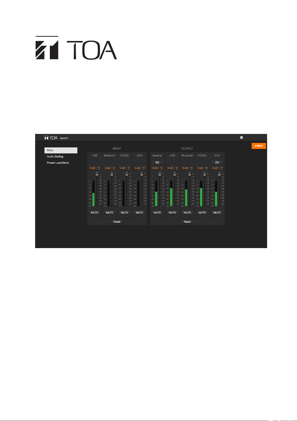
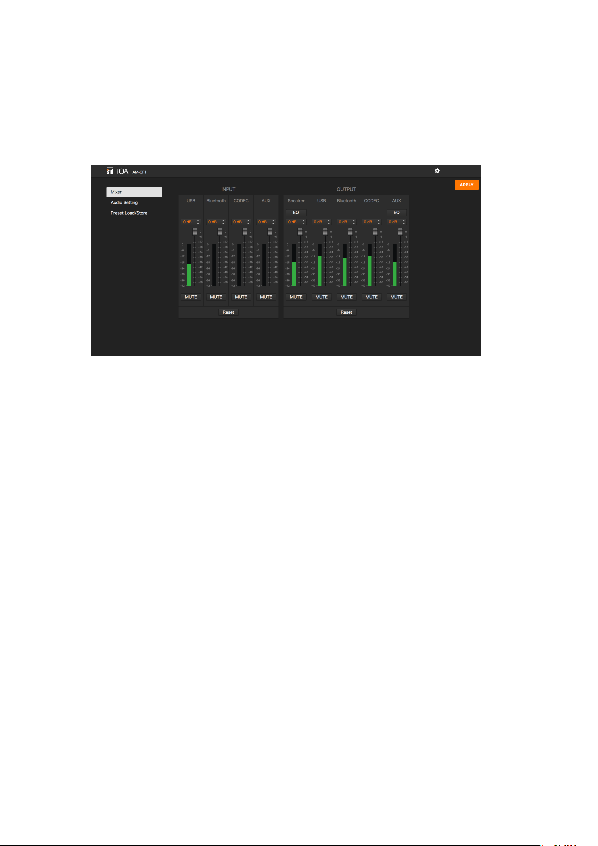
Step 2. Enter a user name and a password.
The mixer screen is displayed.
Note
Do not launch multiple web browsers at the same time.
Tip
Default user name and password are as follows:
User name: amcf1
Password: amcf1guest
4
Page 5
4. SETTINGS
4.1. Settings Screen Switching
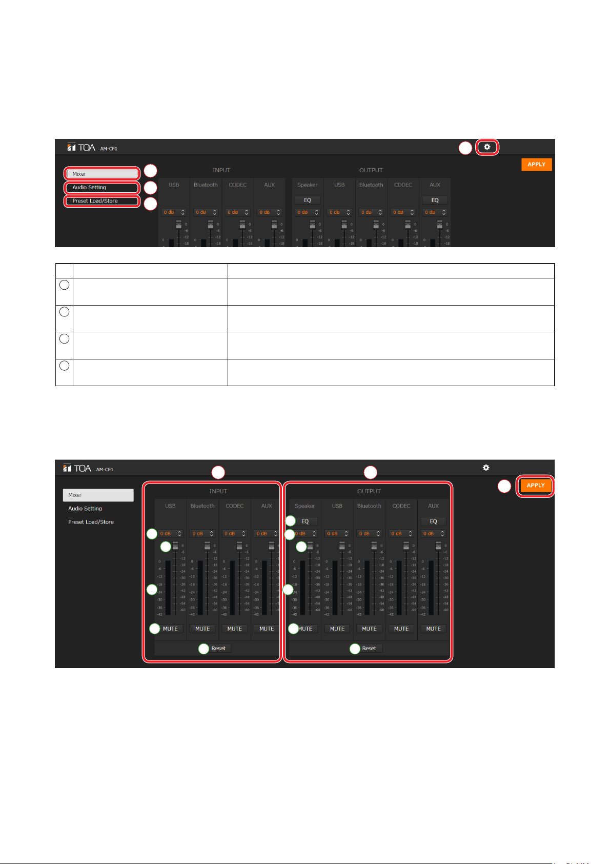
Click the following screen name or icon to switch the settings screen to the desired screen. Perform necessary
settings on each screen.
4
1
2
3
Screen Name or Icon Setting Contents
1
Mixer screen (Mixer) Used to set input and output gains, etc. Equalizer settings are possible
for both speaker and AUX outputs. (See below.)
2
Audio settings screen (Audio
Set ting)
3
Preset data loading and storage
screen (Preset Load/Store)
4
Conguration icon Used to perform settings related to networks, contact control/front
Used to set microphone collection sound parameters, echo cancellers
and noise cancellers. (See p. 9.)
Used to perform settings regarding the methods of loading and storing
preset data. (See p. 11.)
panel LED indication and day and time/rmware update. (See p. 12.)
4.2. Mixer Screen Settings
1
A
C
B
D
E
(1) Input signal adjustment section (INPUT)
Perform settings related to input signals.
The following four input types are made available:
USB
Bluetooth
CODEC
AUX
2
3
F
G
I
H
J
K
5
Page 6

Name Description
A Input gain display Input gains are displayed numerically.
Numerical values can be changed with the arrows to the right of each value.
Initial setting: 0 dB
Tip: Linked to faders (C).
B Input level indicators Display input levels.
C Faders Used to change input gains.
Tip: Linked to input gain display (A).
D Mute button Click to mute corresponding input. Clicking again returns input to the previous
level.
E Reset button Click to return all input adjustment settings to their initial settings.
(2) Output signal adjustment section (OUTPUT)
Perform settings related to output signals.
Settings for the following ve types of output can be performed:
Speaker
USB
Bluetooth
CODEC
AUX
Name Description
F EQ button Performs equalization on both speaker and AUX outputs. Clicking this button
opens the Equalizer Screen. (See p. 7.)
G Output gain display Output gains are displayed numerically. Numerical values can be changed
using the arrows to the right of each value.
Initial setting as follows:
Speaker, USB, CODEC, AUX: 0 dB
Bluetooth: –20 dB
Tip: Linked to faders (I).
H Output level indicators Display output levels.
I Faders Used to adjust output gains.
Tip: Linked to output gain display (G).
J Mute button Click to mute corresponding output. Clicking again returns output to the
previous level.
K Reset button Click to return all output adjustment settings to their initial settings.
(3) APPLY button
Click this button after all settings on this screen are completed. Setting contents are applied.
6
Page 7

[Equalizer Settings]
Clicking the EQ button (see the previous page) displays the equalizer screen.
Both speaker and AUX outputs allow equalizer settings on 5 points and PEQ (parametric equalizer) parameters
can be set on all of the 5 points. In addition, PEQ or HPF (high-pass lter) settings can be performed on the
leftmost point, and PEQ or LPF (low-pass lter) settings can be performed on the ringhtmost point.
(Example: Speaker Output Equalizer Screen)
1
2
A
B C D E
3 4
6
(1) Back icon
Clicking this icon returns the screen to the Mixer Screen.
(2) EQ curve display section
EQ curves are displayed depending on parameter settings.
(3) PEQ/HPF setting section
Used to set PEQ or HPF parameters.
Name Description
A PEQ/HPF selection Select the parameter type (PEQ or HPF).
Initial setting as follows:
Speaker output: HPF
AUX output: PEQ
B Parameter settings Set parameters for Freq (frequency), Gain and Q.
The setting range and initial settings are shown in the table below.
Note: Gain and Q cannot be set if HPF is selected in the PEQ/HPF selection.
7
F
G
5
[Setting Ranges and Initial Settings]
Setting Item Setting Contents Setting Range
PEQ Freq (Hz) 20 to 20000 300 200
Gain (dB) –15 to 15, 0.5 dB steps 0 0
Q 0.267 to 69.249 0.718 4.318
HPF Freq (Hz) 20 to 20000 300 200
Speaker Output AUX Output
Initial Setting
7
Page 8

(4) PEQ setting section
Set Frequency, Gain and Q parameters.
The setting range and initial settings are as shown in the table below:
Setting Item Setting Contents Setting Range
PEQ Freq (Hz) 20 to 20000 C: 300
Gain (dB) –15 to 15, 0.5 dB steps C: –6
Q 0.267 to 69.249 C: 4.318
(5) PEQ/LPF setting section
Used to set PEQ or LPF parameters.
Name Description
A PEQ/HPF selection Select the parameter type (PEQ or LPF).
Initial setting: PEQ
B Parameter settings Set parameters for Freq (frequency), Gain and Q.
The setting range and initial settings are shown in the table below.
Note: Gain and Q cannot be set if LPF is selected in the PEQ/HLPF selection.
Speaker Output AUX Output
D: 600
E: 4000
D: –3
E: 8
D: 4.318
E: 2.145
Initial Setting
C: 630
D: 1600
E: 4000
C: 0
D: 0
E: 0
C: 4.318
D: 4.318
E: 4.318
[Setting Ranges and Initial Settings]
Setting Item Setting Contents Setting Range
PEQ Freq (Hz) 20 to 20000 10000 10000
Gain (dB) –15 to 15, 0.5 dB steps 0 0
Q 0.267 to 69.249 4.318 4.318
HPF Freq (Hz) 20 to 20000 10000 10000
(6) Reset button
Click this button to change the values (3) – (5) of speaker output and AUX output, respectively, as follows:
Setting Item Setting Contents
PEQ Freq (Hz) 200 C: 630
Gain (dB) 0 C: 0
Q 4.318 C: 4.318
(3) PEQ/HPF setting
section
(4) PEQ setting section
D: 1600
E: 4000
D: 0
E: 0
D: 4.318
E: 4.318
Speaker Output AUX Output
Initial Setting
(5) PEQ/LPF setting
section
10000
0
4.318
(7) APPLY button
Click this button after all settings on this screen are completed. Setting contents are applied.
8
Page 9

4.3. How to Set the Audio Settings Screen
Perform settings related to microphone sound collection.
F
A
6
1
B
C
D
E
2
3
G
4
J K
5
(1) Tracking Field
Set the range of sound source tracking with the microphone position (AM-CF1) as a reference. Use distances
to the left and right from the center of the microphone position (AM-CF1) and the distance directly in front
of the microphone to set the range.
Name Description
A Range display The sound source tracking range is displayed in orange.
B X1 axis setting Set the distance from the microphone position in the direction of the X1 axis.
Setting range: 0 to 300 cm (0 to 120 inch)
Initial setting: 200 cm (80 inch)
C X2 axis setting Set the distance from the microphone position in the direction of the X2
axis.
Setting range: 0 to 300 cm (0 to 120 inch)
Initial setting: 200 cm (80 inch)
D Shortest distance setting Set the shortest distance in front of the microphone position.
Setting range: 20 to 590 cm (8 to 236 inch)
Initial setting: 20 cm (8 inch)
E Farthest distance setting Set the farthest distance in front of the microphone position.
Setting range: 30 to 600 cm (12 to 240 inch)
Initial setting: 400 cm (160 inch)
F Unit selection Click to set the unit of distance to either centimeters (cm) or inches. The
selected unit is displayed in orange.
Initial setting: cm
H
I
(2) Tracking Sensitivity
Set the sensitivity to be used to specify a sound source.
Setting range: Low, Mid and High
Initial setting: Mid
9
Page 10

(3) Steering Mode
Set whether or not to track a sound source by clicking “Auto” or “Fixed.”
The set mode is displayed in orange.
“Auto”: Select this when tracking the sound source.
“Fixed”: Select this when the sound source position is xed and thus not being tracked.
Initial setting: Auto
(4) Echo Canceller (AEC)
Name Description
G ON/OFF switching Turns the [AEC] (Acoustic Echo Canceller) mode ON or OFF.
The selected mode is displayed in orange.
Initial setting: ON
H NLP Level setting Sets the setting level for Non-Linear AEC processing.
Setting range: Low, Mid, High
Initial setting: Mid
I Microphone Gain setting Sets the output volume level of the beam steering microphone.
Setting range: –6, –4, –2, 0, 2, 4 and 6 dB
Initial setting: 0 dB
(5) Noise Cancellation
Name Description
J ON/OFF switching Turns the noise cancellation mode ON or OFF.
The selected mode is displayed in orange.
Initial setting: ON
K Attenuation setting Sets the amount of noise attenuation in dB.
Setting range: 6, 9 and 12 dB
Initial setting: 9 dB
(6) APPLY button
Click this button after all settings on this screen are completed. Setting contents are applied.
10
Page 11

4.4. Preset Data Loading and Storage Screen Settings
Preset data contents can be loaded from or stored to a PC.
1
A
B
2
C
E
D
G
F
3
(1) Preset data setting section
Either of two different preset data contents can be selected.
Name Description
A Preset data selection Select the preset contents to use by clicking either “1” or “2.” A checkmark
appears to the right of currently selected preset data.
B Loading (Load) Loads stored setting contents.
C Storage (Store) Stores setting contents. Clicking this button stores current setting contents
as preset data.
D Reset Resets setting contents to their initial settings after storing them as preset
data.
(2) Preset data upload and download
Load or store preset data on a PC.
Name Description
E File selection (Browse) Click when selecting the preset data le (extension: zip) stored on the PC.
F Upload Click when uploading the selected preset data le to the AM-CF1 unit.
Note: Files that do not satisfy lename conditions (see below) cannot be
uploaded.
G Download Click when downloading preset AM-CF1 data for storage on a PC. The
lename when downloading is “amcf1_preset.zip”.
Tip: Filenames can be changed after they are stored on a PC.
Usable characters: Alphanumerics, space, [ _ ], and [ - ]
Maximum number of characters: 32
H I
(3) Preset AM-CF1 data settings at startup
Set which preset data to upload when the AM-CF1 unit is started.
Name Description
H Preset data selection at
startup
I APPLY button Click after selecting the startup preset le contents. The selected setting
From the pull-down menu, select the preset data contents to be uploaded
when the AM-CF1 unit is started.
contents are applied.
11
Page 12

4.5. Configuration Settings
The conguration settings screen is displayed when the conguration icon is clicked.
Perform settings related to the conguration of the AM-CF1 unit.
The following three conguration settings screens are available. Click any one of the screen names shown in
the screen below to switch the screen and perform all necessary settings.
• Network/User
• Control/Indicator
• Time/Firmware
Conguration icon
[Conguration Settings Screen]
12
Page 13

4.5.1. Network/User settings screen
A
B
1
C
D
2
3
(1) Network settings
Perform network settings for the AM-CF1 unit.
Setting Item and Button Description
A IP Address Enter the AM-CF1 unit’s IP address.
Initial setting: 192.168.14.1
B Subnet Mask Enter the AM-CF1 unit’s subnet mask.
Initial setting: 255.255.255.0
C Default Gateway Enter the AM-CF1 unit’s default gateway.
Initial setting: 192.168.14.254
D APPLY button Click after setting entry completion. The set network contents are applied.
E
H
F
G
I
(2) Administrator Setting
Set the network administrator’s user account.
Setting Item and Button Description
E User account name Enter the administrator’s user account name.
Initial setting: amcf1
F Password Enter the password of the user account.
Initial setting: amcf1guest
G APPLY button Click after setting completion. The set administrator contents are applied.
13
Page 14

(3) Bluetooth name settings
The name of the AM-CF1 unit as a Bluetooth device can be entered, conrmed and changed.
Setting Item and Button Description
H Device name Enter a new device name.
The last 4 digits of the initial setting correspond to the last 4 digits of the
device’s MAC address.
Usable characters: Alphanumerics, space, [ _ ], [ - ] and [ . ]
Maximum number of characters: 24
I APPLY button Click after device name entry completion. The entered device name is
applied.
4.5.2. Control/Indicator settings screen
A
1
B
C
2
D
E
3
4
(1) External control settings (Control)
Set the input and output terminal operations to be activated by the contact input and output signals.
Name Description
A Pull-down menus 1
and 2 for contact input
settings
B Pull-down menus 1 and
2 for contact output
settings
Individually set the operation to be performed when a signal is received at
control input terminals 1 and 2.
Setting range: None, Mute (Momentary), Mute (Latching), Vol Up, Vol Down,
Preset 1 and Preset 2
Initial setting: None
Individually set the operation to be performed when a signal is output from
control output terminals 1 and 2.
Setting range: None, Mute Status, Sync In 1 and Sync In 2
Initial setting: None
14
Page 15

(2) LED Indicator settings
Perform indication status settings for the AM-CF1 unit’s front panel-mounted LED indicators (multifunction
indicator).
Name Description
C Tracking display ON/OFF
settings
D Mic Input Gain Level
display ON/OFF settings
E Pull-down menu for
indicator mode selection
during mute status
(3) Key Lock setting
Enables or disables the Key Lock function. Setting the Key Lock function to ON disables the unit’s side
switches. Selected indicator lights orange.
Initial setting: OFF
(4) APPLY button
Click after all settings are completed on this screen. Set contents are applied.
Turn the Tracking display ON or OFF to perform settings. The selected
mode is displayed in orange.
Initial setting: ON
Turn the Mic Input Gain Level display ON or OFF.
The selected mode is displayed in orange.
Select from the pull-down menu whether to turn on all multifunction LED
indicators or only one central indicator when in mute mode.
Central indicator: Single LED
All indicators: LED Bar
Initial setting: LED Bar
15
Page 16

4.5.3. Time/Firmware settings screen
1
A
2
C
B
D
3
F
G
4
E
(1) Date and time settings (Time Setting)
Set the AM-CF1 Unit’s date and time.
Name Description
A Date and time settings Set the date and time by changing their numerical values. When this screen
is displayed, the set date and time of the PC connected to the AM-CF1 unit
is rst shown. The displayed time is not automatically updated.
B APPLY button Click after all necessary time settings are completed. The set contents are
applied.
(2) Firmware update
Read the rmware update le from a PC to update the AM-CF1 unit’s rmware.
Name Description
C File selection (Browse) Click when selecting the rmware update le (extension: bin) stored on the
PC.
D Upload Click when uploading the selected rmware update le to the AM-CF1 unit.
(3) Firmware Version
The AM-CF1 unit’s rmware version is displayed. No modication is possible.
16
Page 17

(4)Congurationdata(CongData)
Upload or store conguration data on a PC.
Name Description
E File selection (Browse) Click when selecting the conguration data le (extension: zip) stored on
the PC.
F Upload Click when uploading the selected conguration data le to the AM-CF1
Unit.
Note: Files that do not satisfy lename conditions (see below) cannot be
uploaded.
G Download Click when downloading the AM-CF1 conguration data le for storage on a
PC. The lename when downloading is “amcf1_cong.zip”.
Tip: Filenames can be changed after they are stored on a PC.
Usable characters: Alphanumerics, space, [ _ ], and [ - ]
Maximum number of characters: 32
URL: https://www.toa.jp/
201910
 Loading...