

Page 1
TOA PROFESSIONAL SOUND SYSTEM
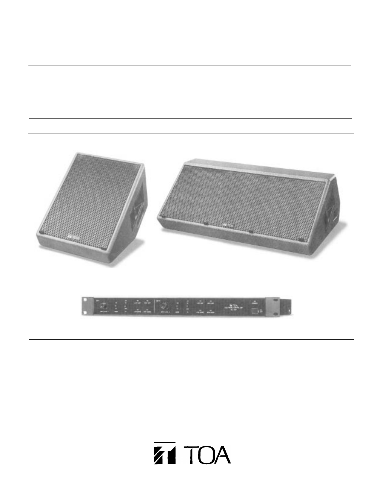
FLOOR MONITOR SPEAKER SYSTEM
SR-M1
SR-M2
AC-M1
Single -Woofer Monitor Speaker
Twin -Woofer Monitor Speaker
Electronic Control Unit
SR-M1
FEATURES
1. 2-way, ported, bi-amplified systems.
2. 40 x 40 degree CD horn/compression driver for HF.
3. Powerful 12” (30cm) LF drivers and titanium HF compression driver.
4. Heavy duty enclosure construction.
5. Phase and driver time offset correction.
6. Active signal processing with sophisticated speaker protection.
7. “Floor Correction” circuitry.
8. Signal dependent limiting parameters.
9. Electronically-balanced inputs and outputs.
10. Neutrik Speakon (for SR’s), XLR (for AC-Ml) connectors.
SR-M2
AC-Ml
Page 2
DESCRIPTION
TOA’s SR-M1 and SR-M2 are actively processed, two way,
Stage/Floor Monitor Systems that feature high power handling,
bi-amplification, porting and the extremely rugged construction
necessary for reliable, portable use. Where every dB counts,
they maximize the audio information most critical to the performer
by addressing problems specific to floor monitors. Both systems
are designed to work with the AC-Ml Electronic Control Unit for
best performance. In one rack space each provides two
independent bi-amp channels, crossover phase alignment, driver
offset time correction, CD (constant directivity) horn EQ to correct
for losses inherent in CD horns, plus both LF and HF limiting.
DRIVERS:
Both systems are two-way, but the SR-M1 has a single
12” (30cm) woofer and the SRM2 has two 12” (30cm) woofers.
The 12” woofers, coupled with their 7.9” (200mm) magnets
(16,200 Gauss flux density), provide high efficiency and excellent
transient response for the lower frequencies. LF power handling
is 300 watts AES (M1) and 600 watts AES (M2)*.
Both systems use the same titanium diaphragm, high frequency
compression driver: the TOA HFD-652. It has a very smooth
frequency response and superb transient reproduction. Its RMS
power rating is a robust 80 watts*. The driver is coupled to a
40 x 40 degree CD horn crossed over at 1kHz. This means
highly efficient, focused HF coverage to cut through ambient
sound levels and reduce on-stage high frequency leakage into
other microphones.
FLOOR CORRECTION:
A unique system feature is the “FC” or “Floor Correction” function.
When slant type monitors operate on a floor, some of their sound
is reflected off the floor, acoustically interfering with their own
direct sound. This causes audible cancellations in the critical
midrange and thus a loss of this information to the performer.
TOA’s engineers designed circuitry into the AC-Ml to correct for
this problem. This means performers will hear more of the critical
information they need at lower levels. Also, the smoothed
frequency response can result in higher gain before feedback.
DRIVER PROTECTION:
The driver protection in the AC-Ml is more than simple limiting.
For example, high pass filters for the LF sections provide
sub-sonic protection. Limiting is done by directly sensing
amplifier outputs. This means the limiters will only respond to
audio actually “seen” by the speakers. Separate limiters with
different processing are used to protect the HF and LF drivers.
The limiting attack and release times are dependent on the
characteristics of the signal, for virtually transparent operation.
Typical LF limiters for bi-amped monitors simply reduce the entire
woofer output when limiting excessive lower frequency signals,
such as kick drum. Unfortunately, this reduces what the
performer needs to hear from the higher frequency portion of the
woofer’s output. The AC-Ml is designed to correct this problem
by being able to limit lower frequencies to the woofer without
limiting the higher frequencies at the same time. Separate overall
LF limiting protects the latter range.
TIME/PHASE CORRECTION:
The frequency response is very smooth, particularly through the
crossover, because of the crossover phase, driver time offset and
frequency response processing provided by the AC-Ml. This
means you get a higher quality monitor mix with less prominent
ring modes, both of which minimize EQ adjustments. The time
domain processing also corrects factor which lead to improved
gain before feedback margins, and that EQ alone could not,
especially when microphones are in the speaker’s proximity.
CONSTRUCTION:
The SR-M1/M2 enclosures are constructed of APITON plywood,
one of the densest, toughest plywoods made. (A more common
use is as the flooring for semi-trailers!) It eliminates undesirable
acoustic effects from cabinet resonances and flexing and it
makes the enclosures extremely rugged for road use. They are
finished in a tough, black epoxy paint with a heavy gauge,
removable, perforated steel grille to protect the drivers. Drivers
can be serviced from the front. No fewer than 8 machine screws
and “T” nuts are used to securely mount the woofers. On both
sides of the enclosure there is a recessed, heavy duty handle
and a Neutrik NL4MPR Speakon connector. The two Speakons
are wired in parallel for loop-through operation.
AC-M1:
The AC-Ml Electronic Control Unit has electronically balanced
inputs and outputs capable of +26dB (ref. OdB=0.775V).
The limiter sense inputs are bridging (10k ohm), allowing
connection to the amplifier outputs using standard shielded pair
audio cable. The front panel includes for each channel: FC Mode
In/Out; Input level; M1/M2 Select; LF/HF Sense Input and Limit
Lights. It has XLR audio and binding post sense connectors.
*Note At least 300 watts per HF and LF driver IS recommended to avoid possible speaker
damage due to clippIng with lower power amplifiers.
INPUT CONNECTOR
Two Neutrik NL4MPR connectors are provided on both sides of
the speaker. They are internally parallel-connected, so either
may be used for loop-through connections,
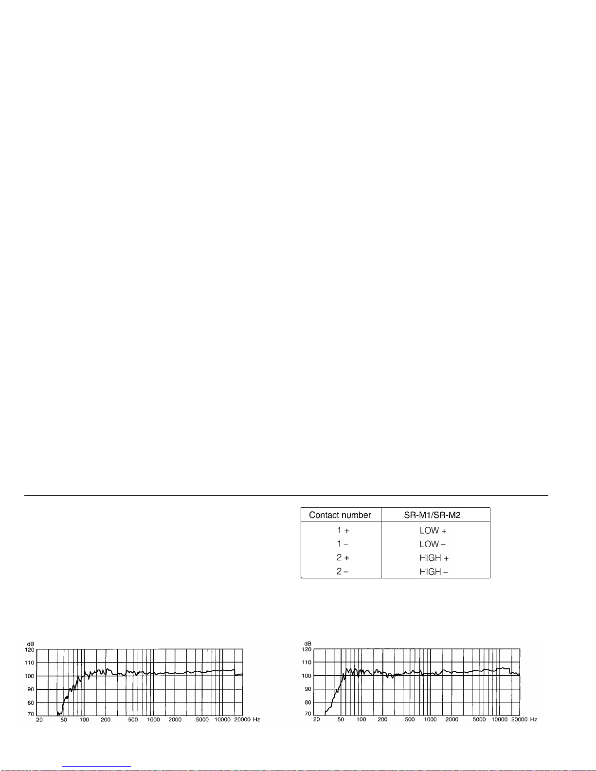
Each connector contact is wired as shown in the right table.
CHARACTERISTIC DIAGRAMS (1/3 Octave Pink Noise)
l SR-M1 (1/4W input/1m, at 2kHz of HIGH frequency)
Applicable cable connector is Neutrik NL 4FC.
l
SR-M2 (1/4W input/1m, at 2kHz of HIGH frequency)
Page 3
Model No.
PERFORMANCE
Total Harmonic Distortion
Noise Level
INPUT & OUTPUT
Nominal Input Level
Nominal Output Level
Maximum Input Level
Maximum Output Level
Sense input
Maximum Sense lnput
Attack Times
Release Times
Limiting Ratio
STANDARD ACCESSORIES
PANEL FUNCTIONS (Front Panel)
Operating Controls (per channel)
Operating Controls (common to both)
LED Indicators (per channel)
LED Indicators (common to both)
-POWER
Power Requirements
Power Consumption
PHYSICAL
Finish
Dimensions
Weight
NOTE: OdB=O.775V RMS
AC-M1
Under 0.05% (1 kHz)
Better than -85dBm
(-110 below max
+4dB, 20k ohms I/P impedance
(electronically balanced)
+4dB into 600 ohms load
(electronically balanced)
+26dB
+26dB
1 Ok ohms input impedance
150V
Dependent on signal characteristics
Dependent on signal characteristics
Approximately
Spare fuse 1
Rack screws [metric] 4
Select Switch
Floor Correction FC In/Out
lnput
Power On/Off
FC
Low Sense
High Sense
Low Limit LF limit active
High Limit HF limit active
Power
AC Mains, 50Hz/60Hz
18W (120V AC version)
16W (220/240V AC version)
Fuse 0.63A 120V/0.2A 220/240V
Black
482.6W x 44.OH x 353.3D mm
(19W x 1.73H x 13.91D in.)
5.0kg (11.0lbs.)
o/p)
10:1 "Soft knee" threshold
Ml or M2 Spkr
Level control
In
Signal at LF sense I/P
Signal at HF sense I/P
On
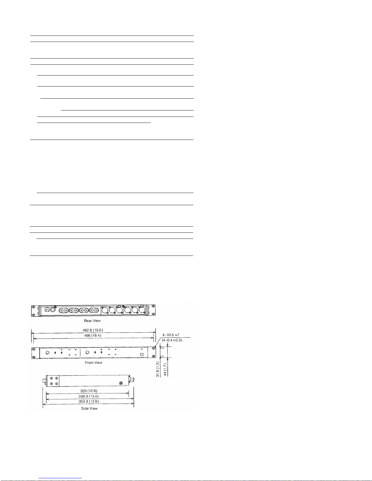
AC-M1
Unit:mm( in.)
*Specifications are subject to change without notice
Page 4
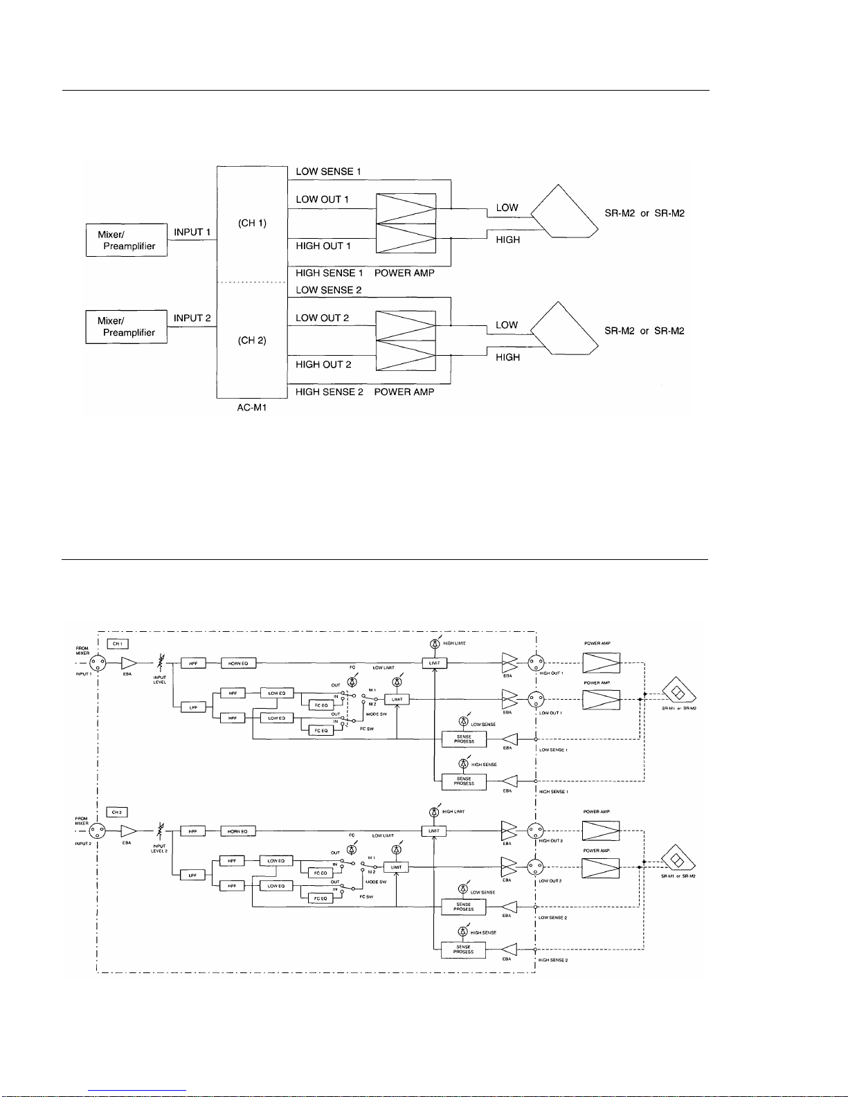
CONNECTION DIAGRAM
BLOCK DIAGRAM
Page 5
SPECIFICATIONS
Model No.
PERFORMANCE
Sensitivity (pink noise 1W/1m) -
Low Frequency (200kHz to 1kHz) 99dB SPL
High Frequency (1kHz to 5kHz)
Frequency Response 70Hz to 20kHz (When used with
AES Power Handling LF
24 Hour Power Handling
LF (50Hz to 1kHz)
Pink Noise
Program
HF (1kHz to 20kHz)
Pink Noise
ELECTRICAL
Nominal Crossover Point
Nominal Impedance LF
Nominal lmpedance HF
PHYSICAL
Low Frequency Driver
High Frequency Driver
High Frequency Horn
Enclosure
Enclusure Material
Enclosure Finish
Perforated Steel Grille Finish
Input Connector
Dimensions
Weight
RECOMMENDED ACCESSORY
NOTE OdB SPL=20uPa NOTE OdB SPL=20uPa
Program
SF-M1
109dB SPL
AC-M1)
300W RMS
120W RMS
360W RMS
80W RMS
240W RMS
1kHz
8 ohms
16 ohms
30cm (12 in.) dia. cone x 1
Titanium comp. driver
CD horn (40 horz x 40 vert)
Ported
Apiton plywood 18mm (0.7 in.) thick
Epoxy paint (black)
Acrylic paint (black)
Neutrik NL4MPR x 2
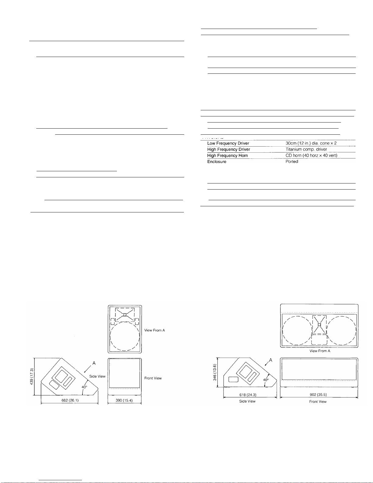
390W x 439H x 662D mm
(15.4W x 17.3H x 26.1D in.)
32kg (71lbs.)
AC-Ml Electronic Control Unit
Model No.
PERFORMANCE
Sensitivity (pink noise 1W/1m) -
Low Frequency (200kHz to 1kHz)
High Frequency (1kHz to 5kHz)
Frequency Response 45Hz to 20kHz (When used with
AES Power Handling LF
24 Hour Power Handling
LF (50Hz to 1kHz)
HF (1kHz to 20kHz)
ELECTRICAL
Nominal Crossover Point
Nominal Impedance LF
Nominal Impedance HF
PHYSICAL
Enclusure Material
Enclosure Finish
Perforated Steel Grille Finish
lnput Connector
Dimensions
Weight
RECOMMENDED ACCESSORY
Pink Noise
Program
Pink Noise
Program
SR-M2
102dB SPL
109dB SPL
AC-M1)
600W RMS
240W RMS
720W RMS
80W RMS
240W RMS
1kHz
8 ohms (2 x 16 ohm)
16 ohms
Apiton plywood 18mm (0.7 in.) thick
Epoxy paint (black)
Acrylic paint (black)
Neutrik NL4MPR x 2
802W x 346H x 618D mm
(35.5W x 13.6H x 24.3D in.)
56kg (123lbs)
AC-Ml Electronic Control Unit
DIMENSIONAL DIAGRAM
SR-M1
SK-M2
Page 6

ARCHITECT’S AND ENGINEER’S SPECIFICATIONS
SR-M2/SR-M1 Monitor Speaker
The loudspeaker shall be a bi-amplified, ported, floor monitor
type system with two 30cm (12 in.) [one 30cm (12 in.)] low
frequency drivers with 200mm (7.9 in.) diameter magnets and
16,200 Gauss flux density in the voice coil gap plus a high
frequency titanium diaphragm, compression driver coupled to a
40 x 40 degree constant beam width horn. The crossover point
shall be 1kHz. The low frequency power rating shall be 240W
RMS (120W RMS ); the high frequency power rating shall be 80W
RMS. Power ratings measured using pink noise with a crest
factor 10dB above RMS from LF50Hz to 1kHz; HF 1kHz to 20kHz
for 24 hours. The frequency response shall be from 45Hz to
20kHz [70Hz to 20kHz] with a sensitivity of LF 102dB [99dB] SPL;
HF 109dB SPL at 1W/1m using pink noise band limited LF 200Hz
to 1kHz; HF 1kHz to 5kHz. The nominal impedance of the system
shall be LF 8 ohms; HF 16 ohms.
The enclosure shall be constructed of APITON plywood 18mm
(0.7 in.) thick, finished with a rugged, black epoxy paint. There
shall be two Neutrik NL4MPR connectors wired in parallel, one at
each end of the enclosure, for “loop through” type connections.
The jacks shall be replaceable with any connector using standard
Canon EP type mounting. The speaker grille shall be perforated
steel painted black acrylic. A heavy duty carrying handle shall be
provided on each end of the enclosure.
The speaker baffle/acoustic axis for the system shall be 50
degrees up from horizontal in the normal operating position.
The enclosure design shall allow positioning for operation with
the speaker baffle/axis aimed horizontally.
The system shall be 902W x 346H x 618D mm (35.5W x 13.6H x
24.3D in.) [39OW x 439H x 662D mm (15.4W x 17.3H x 26.1D
in.)] and weigh 56kg (123lbs.) [32kg (71 Ibs.)].
Recommended Accessory: TOA AC-Ml Electronic Control
Unit-provides phase corrected electronic crossover, CD horn
equalization, Floor Correction function, speaker time off-set
correction and limiting.
The loudspeaker system shall be the TOA SR-M2 [SR-Ml].
NOTE: Acoustic specifications are based on use with the TOA AC-M1 Electronic Control Unit
AC-Ml Electronic Control Unit
The device shall be dual channel, with each channel able to
function independently as an active signal processor/crossover/
limiter for the TOA SR-M1 and SR-M2 speaker systems. Nominal
output level shall be +4dB into 600 ohms (maximum +26dB),
electronically balanced, at less that 0.05% THD at 1kHz. Hum
and noise shall be more than 85dB below 0dB. Nominal input
level shall be +4dB (maximum +26dB); input impedance 20k
ohm, electronically balanced. Gain below the limiter threshold
shall be unity. The limiter sense input impedance shall be 10k
ohms with a maximum input of 150V.
Front panel controls and switches shall include: POWER On/Off
for the unit; INPUT LEVEL; MODE M1/M2 to select speaker type
(SR-M1/SR-M2); FC (Floor Correction) In/Out. Front panel
indicators for each channel shall include: FC IN; Low Sense, High
Sense (detect signals at the sense inputs); Low Limit, High Limit
(sense signals are above limit thresholds). A POWER On
indicator shall also be provided.
The FC IN mode shall provide signal processing, dependent on
the MODE selection (Ml or M2), to correct frequency response
variations at normal listening positions on axis to the speaker
when floor mounted. The variations are those caused by comb
filtering, due to time arrival differences at the listener, between the
direct sound from the speaker and sound from the speaker
reflected from the floor between the listener and speaker.
The FC OUT mode bypasses this processing in both Ml and M2
modes for normal frequency response when the speaker is not
floor mounted.
The unit shall provide separate LF and HF limiters on each
channel for protection of the LF and HF drivers of the SR-MI and
SR-M2 systems from excessive amplifier voltages. Sense input
voltages for the limiter circuitry shall be from the output of the
power amplifiers for those drivers. The limiting thresholds shall
be non-adjustable and factory set at appropriate levels in the
circuitry for the drivers in each system, depending on the MODE
selection (Ml or M2) and shall be independent of amplifier gain.
The gain reduction method for limiting modes shall be approxi-
mately a 10:1 ratio with a “soft knee” threshold. The dynamic
attack and release times shall be dependent both on the MODE
selection (Ml or M2) and on signal characteristics.
Limiting for the LF drivers shall be dependent on the MODE
selection (Ml or M2) and shall allow limiting of excessive lower
frequency signals to the drivers without altering the gain of the
higher frequency signals to the same drivers. An overall LF
limiter shall limit the latter frequencies. Separate limiter circuitry
for the HF drivers shall be provided for each channel.
The unit shall provide a nominal 1kHz, phase corrected,
electronic crossover for the LF and HF drivers. Driver offset time
correction shall also be provided. CD horn equalization shall be
provided to correct for power response loss at high frequencies.
The LF driver equalization shall be dependent on the MODE
selection (Ml or M2) and provide a flat LF frequency response
and protective sub sonic filtering.
The rear panel shall include: two XLR-F for the signal inputs; four
XLR-M for the signal outputs; a pair of banana plug type binding
posts for each of the four sense inputs; a fuse holder with a
replaceable 5/8 amp (2/10 amp 220/240V) fuse with 1 spare fuse
provided.
Power consumption shall be 18 watts at 120V AC (16W 220/240
V AC version). The unit shall be enclosed in a durable, blackcoated 1.0mm (.04 in.) steel enclosure, mechanically reinforced
by a 2.0mm (0.08 in.) thick, black-anodized, aluminum front
panel. Overall dimensions shall be 482.6W x 44.OH x 353.3D
mm (19W x 1.73H x 13.91D in.). Weight shall be 5.0kg (11.0lbs.).
Standard E.I.A. equipment rack mounting shall be provided.
The dual channel signal processor/crossover/limiter shall be the
TOA model AC-M1.
NOTE. 0dB=0.775V RMS
TOA Corporation
Printed in Japan (303) 833-64-539-50
 Loading...