

Page 1
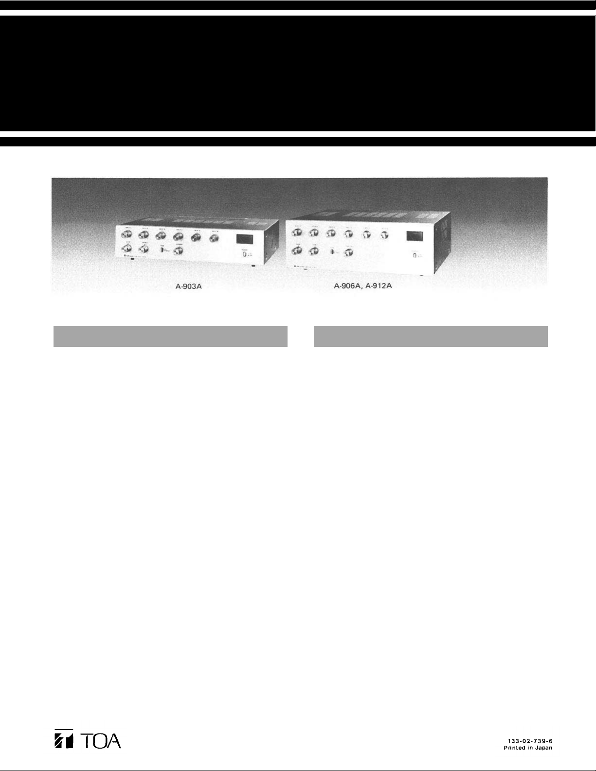
Operating Instruction Manual
TOA NEW 900 SERIES
MIXER POWER AMPLIFIER
Features
General Description
A-903A
A-906A
A-912A
1 6-channel mixer power amplifier
2 Wide frequency response; 20 — 20,000Hz, ±1dB
3 Low distortion and noise level
4 Excellent output regulation
5 Bass and treble controls
6 Bridging input/output
7 Signal processing input/output
8 Self-protect ing circuitry design
9 Varied output impedances; 4 and 8 ohms, 25 and 70 volts
10 A full range of plug-in modules
11 Portable or rack-mounting type
The TOA A-903A, A-906A and A-912A Mixer Power Amplifiers
control and mix up to six independent input signals. The A-903A
deli vers up to 30 wa tts of output power, t he A-906A 60 watts and
the A-912A 120 watts. Optional accessory modules are available for
use with th e A903A, A-906A and A-91 2A to provide versatility for
a wide range of operating applications. Edge connectors on the rear
of the unit permit the selection of the TOA plug-in modules : The
H-01 series, H-02 series and H-03 series Microphone Preamplifiers,
the E-01 and E-11 Mag. Phono Preamplifiers, the X-01 series and
X-11 series Auxiliary Preamplifiers for high-level sources, the B-01
series and B-11 series Bridging Transformers for bridging highimpedance lines, the L-01 series Line Matching Transformers for
matching 600-ohm lines, I-01 Paging Input for combining with TOA
Intercom Systems EXES-1000, EXES-5000 and EX-16, T-01 series
Line Outputs for matching 600-ohm lines and the S-01, S-02 and
S-03 Tone Signal Generators for generating attention-getting signals
and 1 kHz sine wave for testing within the total system. Other
features include a muting function. Sources fed to particular input
module accessories are muted by short-circuiting at MUTE
TERMINALS on the rears. To perform this function, Module E-11,
X-11 series or B-11 series is required.
The TOA A-903A, A-906A and A-912A Mixer Power Amplifiers
have output terminals to match 4- or 8-ohm speaker systems, or
speaker distribution systems may be connected to the 25- or 70-volt
terminals. The A-903A, A-906A and A-912A can be rack mounted
by using Rack-mounting Bracket accessories MB-921 (for A-903A)
or MB-931 (f or A-9 06A and A - 912A). The PF-911 Perforated Panal
(1.73 inches, 1 rack unit) accessory provides suitable ventilation,
finished in color to match the A-903A, A-906A and A -912A.
Toa Electric Co., Ltd.
KOBE, JAPAN
Page 2
TOA NEW 900 SERIES
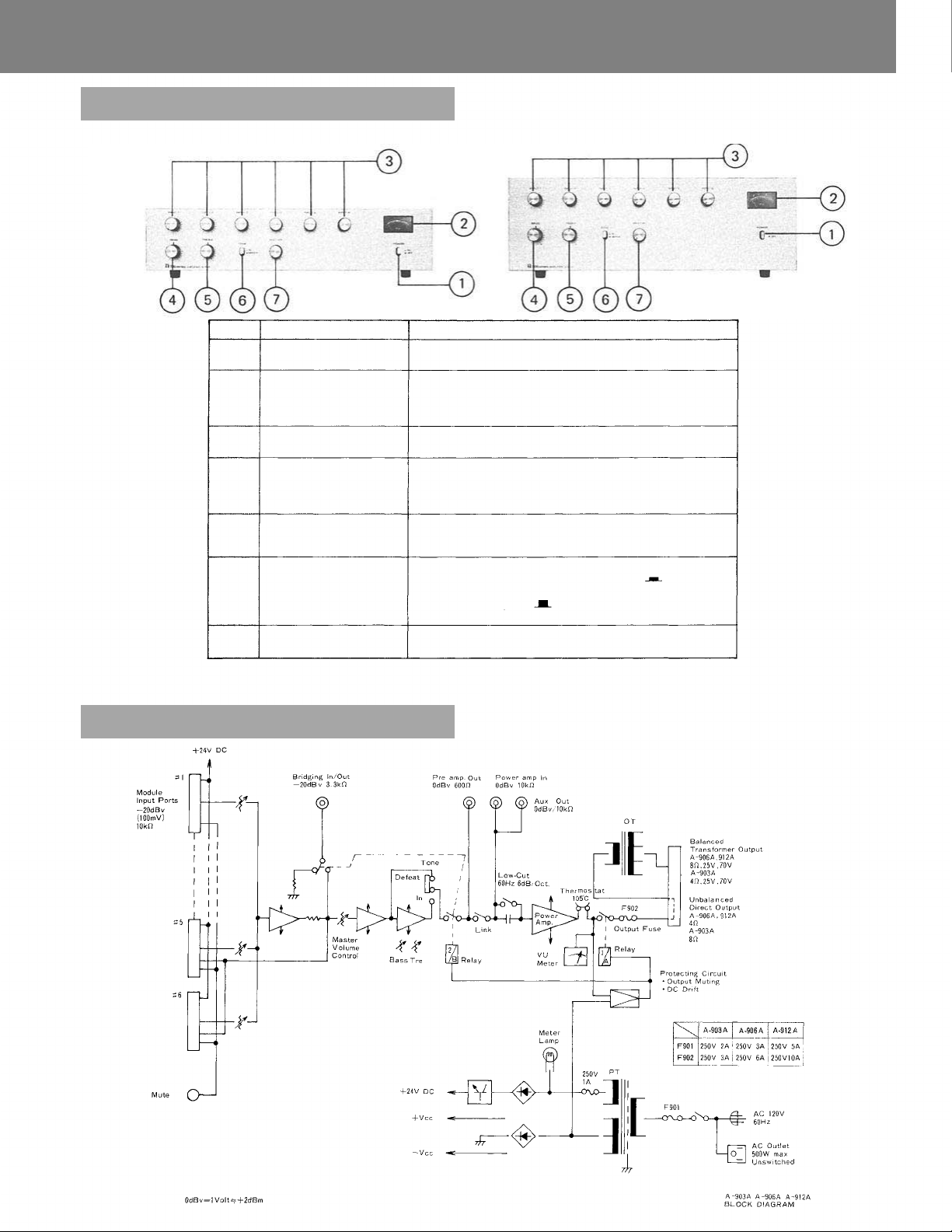
Front Panel Controls and Features
A-903A
Item
1
2
3
4
5
6
7
Name
POWER ON-OFF
SWITCH
METER
INPUT VOLUME
CONTROLS
BASS CONTROL
TREBLE CONTROL
TONE SWITCH
MASTER VOLUME
CONTROL
A-906A, A-912A
Function/Description
Applies line power. Two-position push button
switch for on-off modes.
Indicates the output level of the amplifier. At rated
output, it shows 0 VU (at continuous sine-wave
signal input).
When power is turned on, meter illuminates.
Adjust gain of INPUT #1 – #6 respectively.
Adjusts bass response.
Turn cl o c kw i se ( CW ) to boost and counterclockwise
(CCW) to attenuate the bass response. Tone is flat
at center.
Adjusts treble response.
Turn CW to boost and CCW to attenuate the treble
response. Tone is fla t at center.
Selects IN/DEFEAT of the BASS and TREBLE
Cont rols . When this button is depressed (
BASS and TREBLE Controls are active. ( I N )
Whe n pressed again (
make tone flat. (TONE DEFEAT)
Adjusts overall gain of unit.
), they become i nactive to
), the
Block Diagram
— 1 —
Page 3
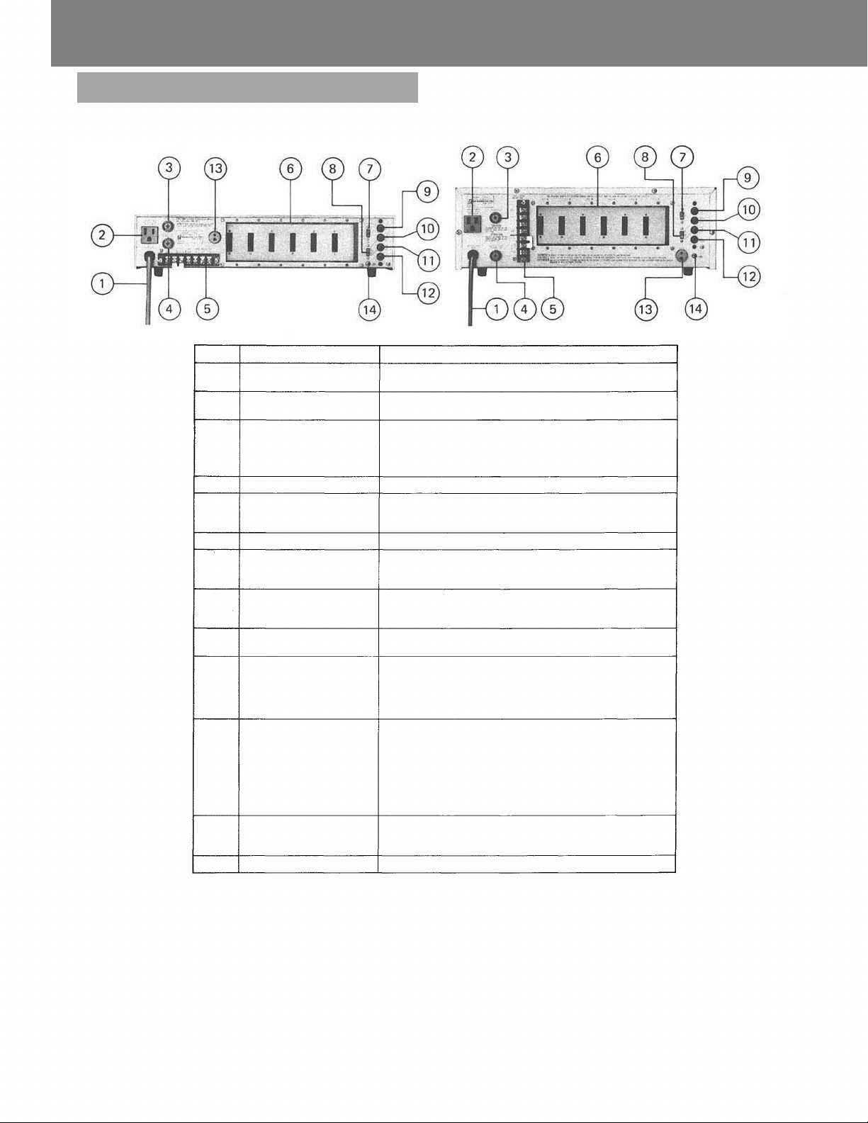
Rear Panel Controls and Features
A-903A
Item
1
2
3
4
5
6
7
8
9
10
11
12
13
14
Name
AC POWER
SUPPLY CORD
AC OUTLET
(Unswitched)
AC FUSE
OUTPUT FUSE
OUTPUT TERMINALS
MODULE INPUT
PORTS
LOW-CUT SWITC H
LINK SWITCH
AUX OUT
POWER AMP IN
PREAMP OUT
BRI DG IN G INPUT/
OUTPUT
MUTE TERMINAL
EARTH TERMINAL
A-906A, A-912A
Function/Description
Connects to power source.
Provides AC power fo r auxiliary equipment with
power consumption of up to 500W.
Prevents excessive current flow.
AC FUSE 250V 2A 250V 3A 250V 5A
OUTPUT FUSE 250V 3A 250V 6A 250V 10A
Connect to speakers.
Accept PLUG-IN MODULES which are optionally
available. Module selection is determined by
application.
Cuts off unnecessary low frequency.
Disconnects between preamplifier and power amplifier
when this switch is turned to the "OUT" side, and
other equipment can be connected.
Provides connections for a booster amplifier or a tape
recorder. The input impedances of the equipment
should be of more than 10k ohms.
When using this terminal, set LIN K SWITCH to "OUT"
position.
Connects to a signal processing equipment such as a
limiter, an equalizer etc. The input impedances of the
equipment should be of more than 600 ohms.
In this case, the LI NK SW should be set in the "OUT"
position.
This terminal is used as a mixing bus. Mixina is achieved
when the similar terminal of another amplifier is
connected to this terminal. The output level taken from
this terminal is independent of the MASTER VOLUME
CONTROL, BASS and TREBLE CONTROLS so that the
terminal can also be used as recording output. The
input impedances of the equipment to be connected
here should be of more than 10k ohms.
With modules employing muting function, which are
optionally available, the input signals fed to the
modules are muted by short-circuiting at this terminal.
Normally connects to a record player's ground.
(A-903A) (A-906A) (A-912A)
— 2 —
Page 4
TOA NEW 90 0 SERIES
Input Connections
This unit has six INPUT PORTS for PLUG-IN MODULES. Select
the desired ones for each application.
Plug the modules into INPUT PORTS, sliding them between the
guide rails, and secure each with two screws.
When not all INPUT PORTS are occupied, cover the vacant
PORTS with blank panels, and secure them with screws.
PLUG-IN MODULES are provided in the following:
Balanced low impedance microphone
premp module (with presettable low-cut
filter, high-cut filter and gain controls)
Balanced low impedance microphone
preamp module (wit h presettable low-cut
filter and gain controls)
Equalized mag. phono preamp. module
(with presettable gain control)
Unbalanced high impedance auxiliay
preamp module (with presettable
gain control)
Balanced 10k
Balanced 600
transformer module
Balanced paging input module
(with presettable gain control and MUTE Delay)
Balanced 600
(with presettable gain cont rol)
Signal tone generator module
(with presettable output level control)
1kHz sine wave
Yelp and buzzer
One-tone chime and co ntinuous one-tone chime
*With H-21 , H-22 and X-21 modules employing volume remote
control functions, connecting a potentiometer (10k ohms) to the
terminal of any of these modules permits the sound volume to be
remotely controlled by means of the connected potentiometer.
* H-31 and H-32 modules incorporate muting functions. If a switch
is connected to MUTE TERMINAL on the rear panel of the ampl i-
fier and closed, these input signals can be passed through. When
the switch is opened, the input signal is muted.
* E-11, X-11, B-11 and L-11 modules incorporate muting functions.
If a switch is connected to MUTE TERMINAL on the rear panel
of the amplifier and closed, these input signals can be muted.
* L-41 incorporates signal activated muting function. Incoming
input signal causes mute terminal to be grounded.
* T-01 is used to feed out mixed signals to external equipment.
*T-01 should be inserted o nly in INPUT POR T #5 or #6.
(See PLUG-IN MODULES for details)
bridging transformer module
line matching
line output module
H-01,
H-02,
X-01,
L-01,
H-21,
H-31
H-22,
H-32
E-01,
E-11
X-11,
X-21
B-01 , B-11
L-11,
L-41
T-01
I-01
S-01
S-02
S-03
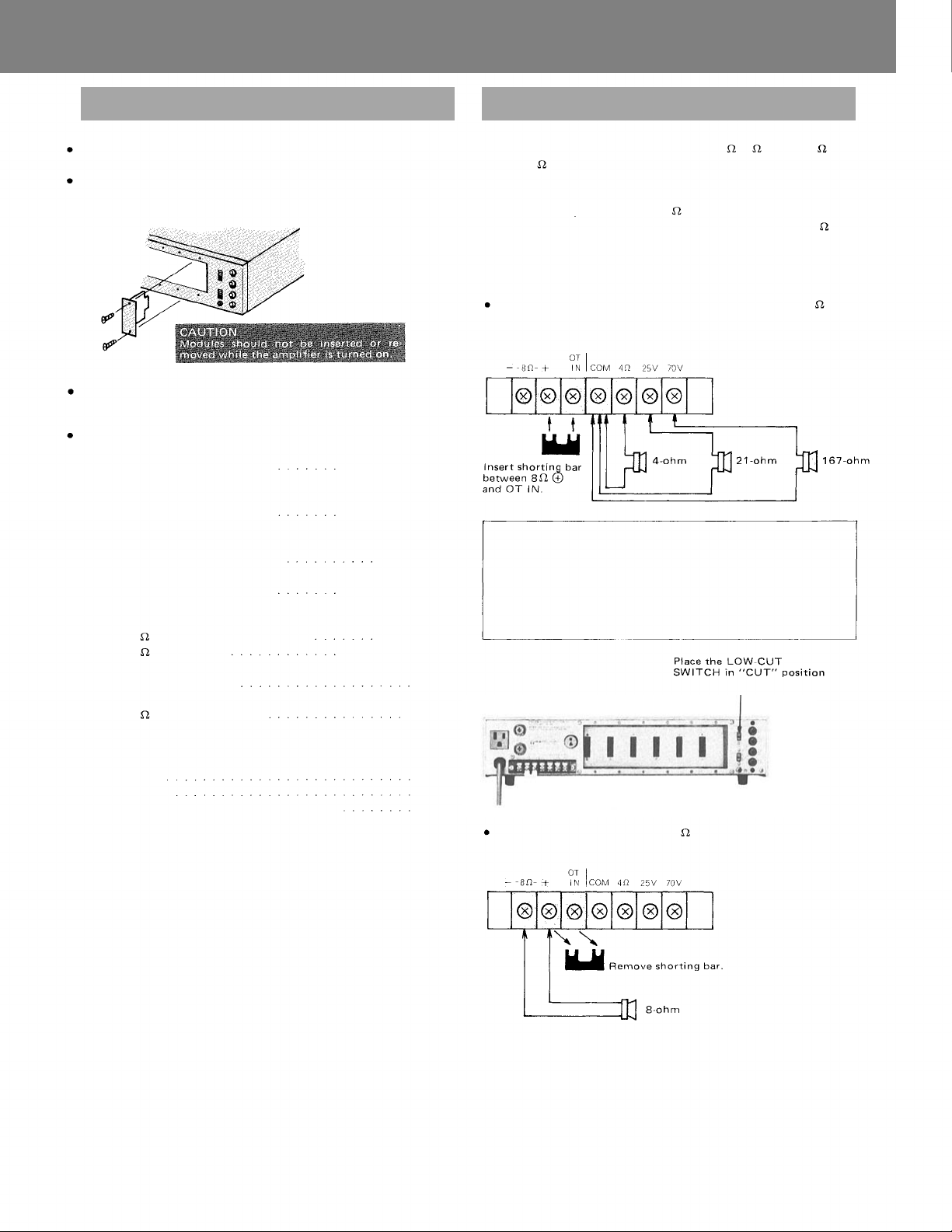
Output Connections A-903A
The speaker outputs of the amplifier are 4
70V
(167
Connect speakers to one of these outputs.
Class 2 wiring may be used.
Since these outputs consist of 4
transformer (matching transformer) and direct output of 8
connecting method differs in each case.
See the following diagrams.
Note: Impedances indicated below imply total speaker system
When connecting speakers to any one of the outputs of 4
or 70V
(BALANCED TRANSFORMER OUTPUT);
Note:
In this case, the LOW-CUT SWITCH should be in "CUT" posi-
tion. This amplifier is characteristically flat even in the low
frequency range. Therefore, in TRANS OUTPUT, the acoustic
effect and frequency-response characteristics may be altered.
In TRANS OUTPUT, cut off unnecessary low frequency to
obtain the best acoustic condition.
When connecting speakers to the 8
(UNBALANCED DIRECT OUTPUT);
).
, 25V and 70V via the output
(load) impedances.
output.
8
,
, 25V (21
) and
, the
,25V
— 3 —-
Page 5
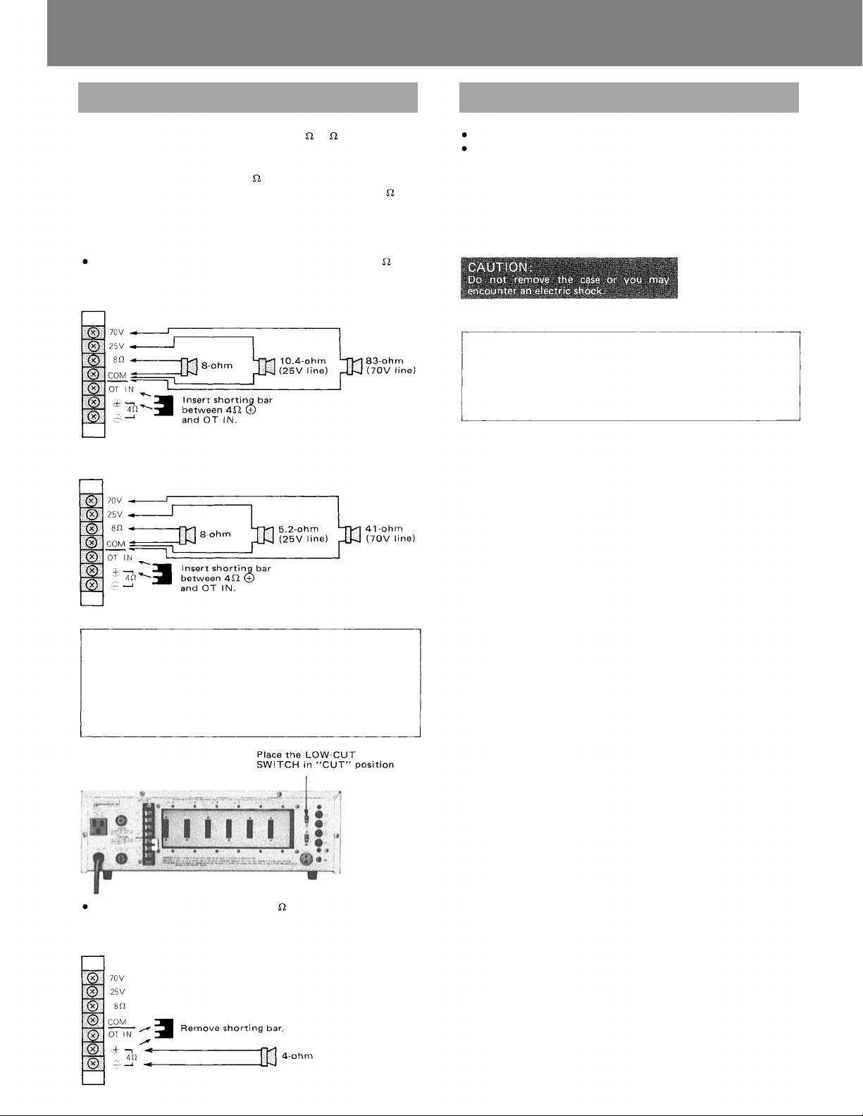
Output Connections P-906A, P-912A
Installation
, 8
The speaker outputs of the amplifier are 4
Connect speakers to one of these outputs.
Class 2 wiring may be used.
Since these outputs consist of 8
transformer (matching transformer) and direct output of 4
connecting method di ffers in each case. See the following diagrams:
Note: Impedances indicated below imply total speaker system
(load) impedances.
When connecting speakers to any one of the outputs of 8
or 70V (BALANCED TRANSFORMER OUTPUT);
(A-906A)
(A-912A)
, 25V and 70V via the output
, 25V and
70V.
, the
, 25V
Do not block cover ventilation holes.
The amplifier should not be placed in areas;
1 with poor ventilation.
2 exposed to direct sunlight.
3 with high ambient temperature or adjacent to heat-generating
equipment.
4 with high humidity or dust levels.
5 susceptible to vibration.
Note:
When the temperature of heat sink exceeds 105°C, the protection circuit is activated and the output is disconnected from the
circuit. The signal automatically begins to be output as the
temperature goes down. In such a case, confirm whether or not
unit is overloaded or operated on an excessive output.
Note:
In this case, the LOW-CUT SWITCH should be in "CUT" position. This amplifier is characteristically flat even in the low
frequency range. Therefore, in TRANS OUTPUT, the acoustic
effect and frequency-response characteristics may be altered.
In TRANS OUTPUT, cut off unnecessary low frequency to
obtain the best acoustic condition.
When connecting speakers to the 4
DIRECT OUTPUT);
(A-906A, A-912A)
output. (UNBALANCED
— 4 —
Page 6
TOA NEW 900 SERIES
Operation
When all connections are completed, turn power swit ch on.
Then, the meter is illuminated. Approx. 5 seconds after switching
power on, the amplifier comes into operation.
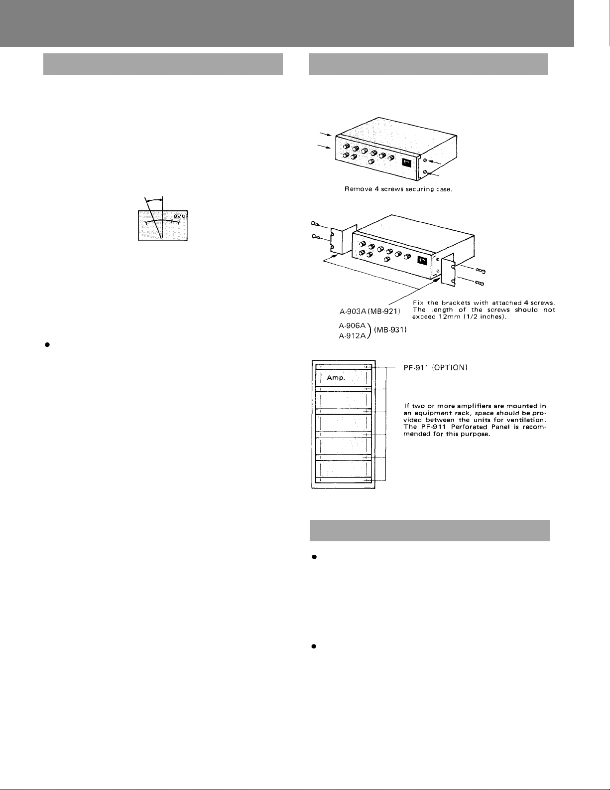
ADJUSTMENT OF VOLUME
Adjust the individual input and master volume controls to obtain
appropriate output level. In normal use of BGM playing or announcement, the deflection of the meter is recommended to be
within the range as indicated in the drawing. Tone quality will be
considerably deteriorated if the pointer indicates around 0 VU.
ADJUSTMENT OF TONE QUALITY
When adjusting tone quality, place the TONE SWITCH in "IN"
position, thus activating the BASS and TREBLE CONTROLS. Each
control provides frequency-response characteristics of flat in center,
boost in CW and attenuation in CCW positions.
When tone controls are unnecessary, place the TONE SWITCH in
"DEFEAT" mode.
Output fuse
Each amplifier has an output fuse to protect the amplifier from
short-circuiting at the output or overloading. Check the fuse when
speakers connected do not sound even if the meter deflects
normally. If the fuse blew, replace with the same type fuse after
confirming the following points.
1 Speaker cables are not short-circuited or the load does not
exceed the rating specified.
2 Wiring is correctly done at the output terminal board.
Rack Mounting
To mount the amplifier in a standard 19-inch equipment rack, use
the MB-9 21 or MB-931 Rack-mounting Bracket accessory. (OPTION)
Servicing
Unpacking
Upon receipt of the amplifier shipment, please inspect for any
damage incurred in transit. If damage is found, please notify your
local TOA representative and the transportation company im-
mediately.
State date, nature of damage, whether any damage was noticed on
the shipping container, prior to unpacking. Please give waybill
number of shipping order.
Failure
Should amplifier fail, contact your nearest TOA authorized contractor or service center.
— 5 —
Page 7
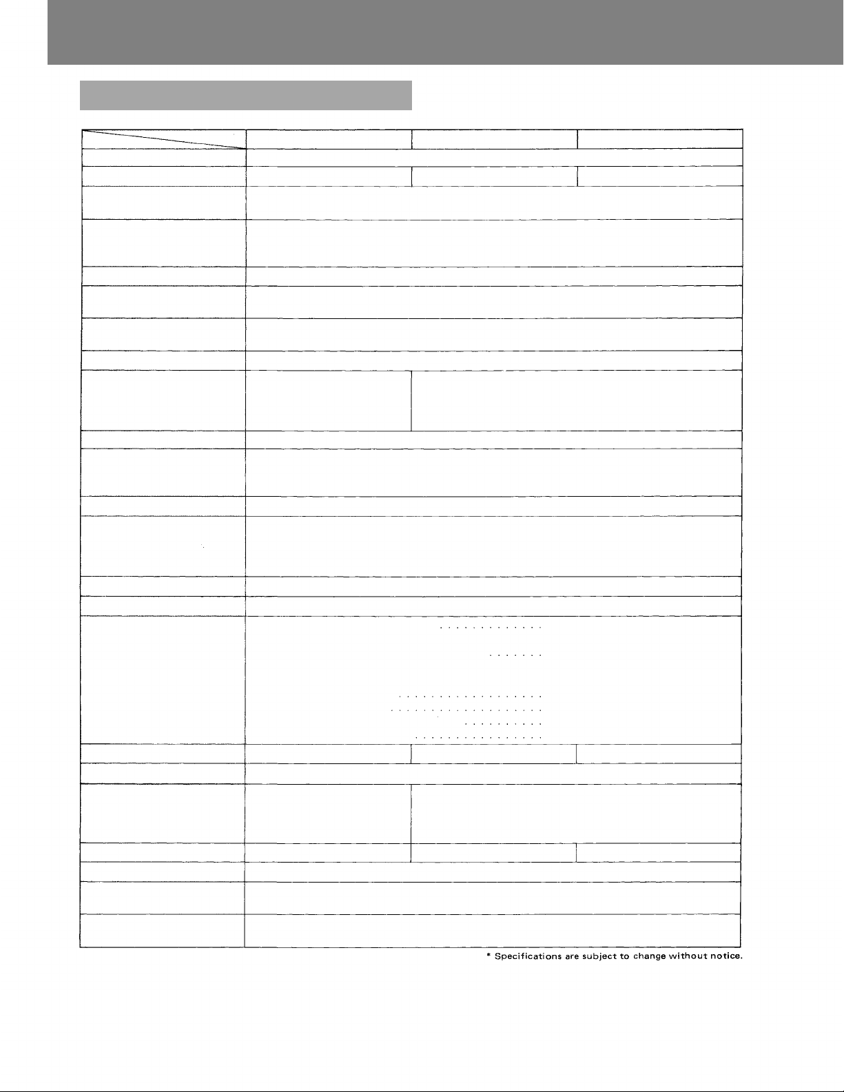
Specifications
Type
Output Power
Power Band Width
Frequency Response
Total Harmonic Distortion
Inputs
Input Sensitivity/Impedance
Preamp OUT/Power Amp IN
Outputs
(D) = Direct
(T) = Transformer
Output Regulation (1 kHz)
Signal to Noise Ratio
(Band
Pass
20 —
20,000
Hz)
Tone Controls Centered
Tone Controls
Controls
Indicator
Protection
Connectors
Power Consumption
Temperature Range
Dimensions in mm (inches)
(high) x (wide) x (deep)
Weight (without input modules)
Color
Standard Accessories
Other Features
A-903A
6-channel mixer power amplifier
30 watts RMS
20 — 20,000 H z, 0.5% THD
(D)
50 — 20,000 H z, 0.5% THD
(T)
(D) 20 — 20,000 Hz, ±1 dB
(T ) 20 — 15,000 H z , ±1 dB
(T) 20 — 20,000 Hz, ±1dB
0.02% at 1 kHz, rated output
Si x Input Ports: Each port accepts any input module except T-01. Use T-01 only in port #5 or #6.
One Bridging Input/Output
Input Ports #1 to #6 : 100 mV/10k ohms
Bridging Input/Output: 100 mV/3.3k ohms
1,000 mV into 600 ohms/1,000 mV, 10k ohms
Main (T ): 4 ohms, 25 & 70 volts
Ma in (D): 8 ohms, unbalanced
Aux : 10k ohms, 1,000 mV
AC 120 volts, 60 Hz, 60 watts
101 (3.98") x 420 (16.54")
x 265 (10.43")
Rack-mounting space size "2U"
(3.46")
balanced
(D ) Less than 0.5 dB , no load to fu l l load (T ) Less tha n 1.0 dB, no load t o fu ll load
Master volume min. : 90 dB
Master volume max . : 77 dB
Power amplifier only: 105 dB
Bass; ±10 dB at 100 Hz: Treble; ±10 dB at 10 kHz
6 Input gain controls
1 Bass tone control
1 Power ON/OFF switch
1 Tone defeat switch
1 Illuminated VU meter
Self-protection, with 2 AC fuses (1 inside) and 1 output fuse.
Input #1 to #6
Bridging
Mixer preamp. output
Power amp. inpu t
Aux output
Output
Mute
AC power cord/plug
AC outlet
AC 1 20 volts, 60 Hz, 100 watts
-10°C to +60°C (12°F to 140°F)
7.3kg (16.1 Ibs.)
2 Volume control covers
1 Mute terminal plug
Output disconnected for approx. 5 sec after switching power on.
Muting Function; Accomplished by model E-11, X-1 1, B-11
A-906A
60 watts RMS
— 3 dB
Main (T ) : 8 ohms, 25 & 70 volts, balanced
Main (D ): 4 oh ms, unbalanced
Aux : 10k ohms, 1,000 m V
1 Master gain control
1 Treble tone control
1 Link switch
1 Low-cut switch (60 Hz, 6 dB/octave)
Card-edge connector
RC A phono jack
Screw-terminal strip
2P Socket
SJT, 3-prong type
3-pin grounding type
AC 120 volts, 60 Hz, 180 watts
14 5 (5.71") x 420 (16.54") x 315 (12.40")
Rack-mounting space size "3U" (5.21")
11.4
kg
(25.1
Ibs.)
Silver
A-912A
120 watts RMS
15.2
kg
(33.4
Ibs.)
— 6 —
Page 8
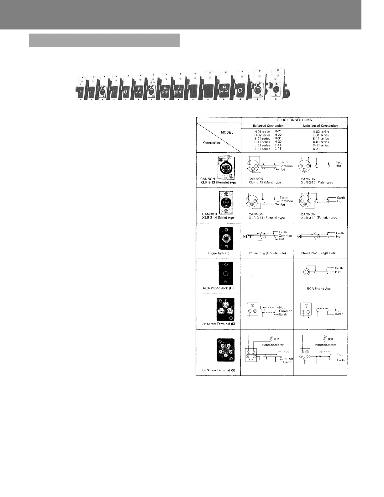
TOA NEW 900 SERIES
Plug-in Modules and Accessories
(OPTION)
The TOA PLUG-IN MODULES are suitable for TOA 900 SERIES
MIXER POWER AMPLIFIERS A-901A, A-903A, A-906A, and
A-912A MIXER PREAMPLIFIER M-900A, an d POWER AMPLI-
FIERS P-906A, P-912A and P-924. Owing to wide selection of
MODULES, the desired applications will be obtained. The various
types of connectors can also meet the needs of equipment to be
connected. MICROPHONE PREAMPLIFIER H-01 series, H-21 and
H-31 incorporates controls for high-cut, low-cut and gain, H-02
series, H-22, H-32 and H-03 series controls for low-cut and gain.
A gain control is built in MAG. PHONO PREAMPLIFIERS E-01
and E-11 series, AUXILIARY PREAMPLIFIERS X-01 and X-1 1
series and X-21, PAGING INPUT I-01 and LINE OUTPUT T-01
series. T-01 series is an output module with transformer, serving
as a line output for recording, etc..
PAGING INPUT I-01 is specially designed to associate with TOA
INTERCOM SYSTEMS. It accepts paging signals fr om the intercom
station.
A group of special signal generating modules is also available for
catching-attention before announcement and testing within th e total
system. ALL PLUG-IN MODULES have handles on their front for
easy insertion and removal.
(INPUT CONNECTIONS, T-01 OUTPUT CONNECTION)
Features:
1. Wide dynamic range
2. Low noise and distortion
3. Wide frequency response
4. Built-in remote volume control circuit (available for models
having 20's in its model number such as H-21)
5. Built-in muting circuit to mute incoming signal when MUTE
TERMINAL is grounded. (available for modules having 10's in
its model number such as X-11)
6. Built-in muting circuit to deliver output signal when MUTE
TERMINAL is grounded, (available for modules having 30's in
its model number such as H-31 )
7. Built-in signal activated muting function (L-41)
8. Presettable gain control (except for B-01, B-11, L-01 and L-11)
9. Microphone modules furnished with tone controls (H-01, H-02,
H-21, H-22, H-31, H -32
and
H-03)
— 7 —
Page 9
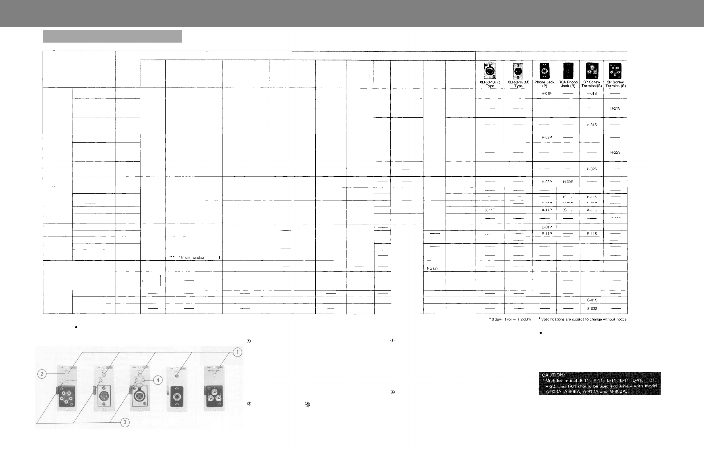
TOA NEW 900 SERIES
Plug-in Modules
Microphone
Preamplitier
Mag. Phono
Preamplifier
Auxiliary
Preamplifier
Bridging
transformer
Line Matching
Transformer
Paging Input
Line Output
Tone Signal
Generator
Applications
Low Z MIC
with Low & High filters
Low Z MIC
with Low & High filters
and remote volume
control facilities
Low Z MIC
with Low & High filters
and MUTE
Low Z MIC
with Low-cut filter
Low Z MIC
with Low-cut filter
and remote volume
control facilities
Low Z MIC
with Low-cut filter
and MUTE
High Z MIC
with Low-cut filter
———
with MUTE
with MUTE
with remote volume
control facilities
with MUTE
———
with MUTE
with Sign al Activating
Mute
1 kHz Sine Wave
Buzzer/Yelp
One Tone Continuous
Chime Chime
Module
Types
H-01 series
H-21
H-31
H-02 series
H-22
H-32
H-03 series
E-01 series
E-11 series
X-01 series
X-1 1 series
X-21
B-01 series
B-11 series
L-01 series
L-11
L-41
I-01
T-01 series
S-01
S-02
S-03
Source
Impedance
Balanced
200 ohms
Unbalanced
50k ohms
Unbalanced
50k ohms
Unbalanced
220k ohms
Balanced
10k ohms
Balanced
600 ohms
Balanced
600 ohms
[Output
Balanced
600 ohms]
Input Sensitivity
for Rated Output (100 mV)
nominal 1.0 mV
adjustable 0.25~25 mV
nominal 3.2 mV
adju stab le 0.8~8.0 mV
nominal 3.2 mV
adjustable 2.0~5.0 mV
nominal 100 mV
adjustable 100~3,200 mV
125mV
125mV
[M in . 15 mV to activate]
125mV
nominal 3.2V
adjustable 3.2~10V
Gain
nominal 40 dB
adjustable 52~32 d B
nominal 30 dB
adjustable 42~22 dB
nominal 34 dB
adjustable 34~26 dB
nominal 0 dB
adjustable 0~—30 dB
—1dB
—2dB
nominal — 30 dB
adjustable —30~— 40 dB
nominal 20 dB
adjustable 20~4 dB
(1.0V output)
(1.0V~158
mV)
Specifications
Max. Before Clip
into 10k-ohm load
at less than 0.5% THD
(1 kHz)
[Output Voltage: ]
[S-01, S-02, S-03 ]
6. 3V (+16 dBv)
6.3 V (+16 dBv)
6.3V (+16 dBv)
6.3V (+16 dBv)
6.3 V (+16 dBv)
4.7V
(+13.4
(-6
dBv)
dBv) 0.5%
into 600-ohm load
0.5V
1 V peak to peak
1 V peak to peak
THD
Frequency
Response
±1dB
25~20,000 Hz
20~20,000 H z
RIAA
Equalized
20~20,000 H z
20~20,000 H z
20~20,000 H z
500~20,000 Hz
Low-cut 25 0 H z
30~20,000 H z
Noise Level
[equivelent]
[ Input noise]
[ or S/N ]
—126 dBm
200 ohms
terminated
S/ N 70dB
S/N 70 dB
S/N 90 dB
———
S/N 80 dB
S/N 80 dB
S/N 80 dB
S/N 80 dB
Signal
Muting
Level
———
60 dB
60 dB
———
60 dB
———
60 dB
———
60 dB
———
60 dB
Remote volume
control range
[use 10k ohms]
[potentiometer]
———
0~— 60 dB
———
0~—60dB
0~—60
dB
Controls
[pre-
settable]
1-Low
cut
1-High c u t
1-Gain
1-Low
cut
1-Gain
1-Low
cut
1-Gain
1-Gain
1-Gain
1- Sensitivity
1-Mute
1-Gain
1-Output
1-Output
1-Output
Weight
105 gr
100 gr
105 gr
100 gr
95 gr
105 gr
60 gr
50 gr
55 gr
70 gr
75 gr
65 gr
90 gr
95 gr
90 gr
95 gr
95 gr
100 gr
100 gr
55 gr
60 gr
70 gr
(max.)
(3.71
(3.53
(3.70
(3.53
(3.35
(3.70
(2.12
(1.76
(1.94
(2.47
(2.65
(2.29
(3.17
(3.35
(3.17
(3.35
(3.35
(3.53
(3.53
(1.94
(2.12
(2.47
oz)
oz)
oz)
oz)
oz)
oz)
oz)
oz)
oz)
oz)
oz)
oz)
oz)
oz)
oz)
oz)
oz)
oz)
oz)
oz)
oz)
oz)
H-01F
H-02F
X-01F
X-11F
B-01F
B-11F
L-01F
H-01M
H-02M
T-01M
Connector
X-01P
L-01P
T-01P
E-01R
-11R
X-01R
-11R
H-02S
E-01S
X-01S
-11S
X-21S
B-01S
L-01S
L-11S
L-41S
I-01S
T-01S
S-01S
FORNT PANEL CONTROLS AND FEATURES
Modules with built-in controls are provided in the following five
types.
— 8 —
GAIN CONTROL
SENSITIVITY
CONTROL (L-41S)
NOMINAL POSITION
MARK
This adjusts gain. Turn clockwise (CW)
to increase and counterclockwise (CCW)
to reduce gain.
Set th e gain as low as possible, the re by ,
noise can be reduced, and the maximum
permissible inp ut level is raised.
This adjusts sensitivity for muting other
modules having MUTE function. Turn
CW to raise and CCW to lower sensitivity.
Setting position should depend on the
equipment connected with L-41S.
The left figure shows nominal
setting of controls.
LOW-CUT FI LT ER
CONTROL
330Hz, 6dB/oct
(max. attenuation)
MUTE DELAY
CONTROL (I-01S)
HIGH-CUT FIL TER
CONTROL
4.2kHz, 6dB/oct
(max. attenuation)
This provides flat characteristics at full
CW position and attenuation in low
frequency by turning CCW. Adjust it to
obtain proper to ne quality. With low-cut,
tone beco mes clear.
This adjusts MUTE delay time which is
the duration from signal input to its
output. Turn CW to shorten and CCW
to lengthen the ti me.
This provides flat characteristics at full
CW position and attenuation in high
frequency by turning CCW. Adjust it to
obtain proper tone quality. With high-
cut, to n e becomes soft.
SPECIFICATIONS IN COMMON
Load impedance
Mounting
Dimensions in mm (inches)
: 10k-ohms
: Card-edge connector
: 78(3.07)x35(1.38)x88(3.46)
(H) x (W) x (D)
— 9 —
Page 10
TOA NEW 900 SERIES
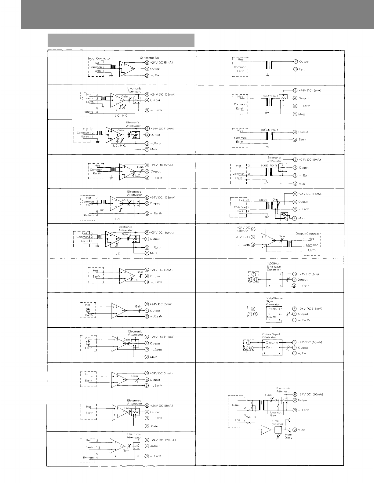
Block Diagrams (Plug-in Modules)
H-01 Series
H-21S
H-31S
H-02 Series
H-22S
H-32S
B-01 Series
B-11 Series
L-01 Series
L-11S
L-41S
T-01 Series
H-03 Series
E-01 Series
E-11 Series
X-01 Series
X-11 Series
X-21S
S-01S
S-02S
S-03S
I-01S
— 10 —
Page 11
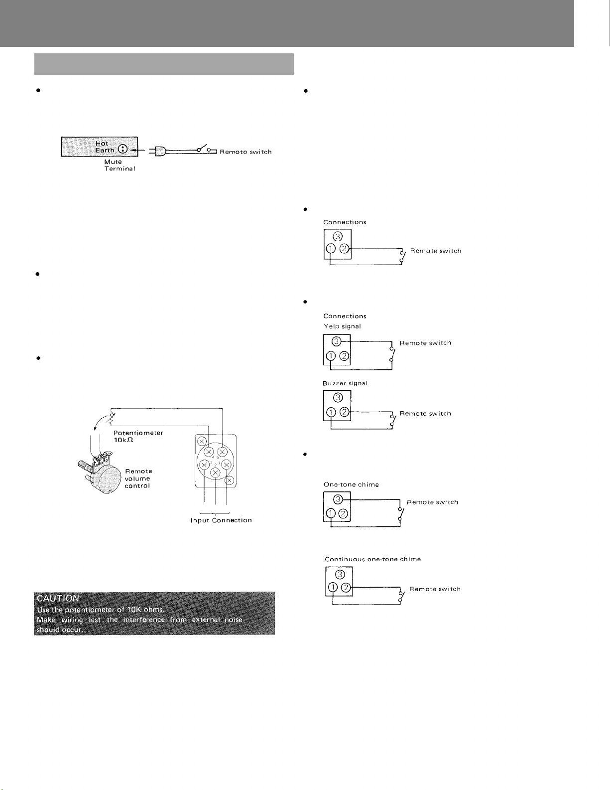
Operation
and
Connections
(Plug-in Modules)
E-11, X-11, L-11, B- 11 Series, H-31 and H-32 (with mute)
Connections
(M-900A, A-903A, A-906A, A-912A)
Operation
When the switch is closed,
a. the signal fed to E-11, X-11, L-11 and B-11 are attenuated by
approx. 60dB. Accordingly a microphone can have a priority at a
time of announcement.
b. the signal fed to H-31 and H-32 are delivered to the amplifier.
(While the swtich is opened, the signals are attenuated.)
L-41 (with signal activated muting facilities)
When this module accepts the input signal, the mute terminal is
grounded automatically without connection of the remote switch
to the MUTE TERMINAL. It causes the other modules wit h mute
function, like X-11, to be muted.
Accordingly the signal fed to the L-41 can have a priority.
H-21, H-22 and X-21 (Remote volume control facilities)
Connections
T-01 SERIES (BALANCED 600-ohm LINE OUTPUT MODULES)
This series of modules, of rated output level 1 volt, is used for
transmitting mixing signals of amplifiers to external equipment and
as a REC
out.
It is provided with a presettable gain control.
T-01 Series should be used exclusively for TOA 900 series, A-903A,
A-906A, A-912A and M-900A. Use it only in Input Port #5 or #6 of
the above models. It will not operate when connected into other
PORTS.
Approx. 5 seconds after power has been supplied to these modules,
the output signal is transmitted.
S-01 (1,000Hz SINE WAVE)
It is operated by closing the remote
switch.
S-02 (YELP AND BUZZER)
Each signal is generated by closing cor-
responding remote switch.
Operation
Preset the gain control of module and the input volume control of
the corresponding input so that an appropriate sound level may be
obtained through the remote volume control.
S-03 (ONE-TONE CHIME AND CONTINUOUS ONE-TONE
CHIME)
CONNECTIONS
By closing the remote switch, chime
sounds once.
By closing the remote switch, one-tone
chime sounds continuously during the
closure of the switch
— 11 —
Page 12
TOA NEW 900 SERIES
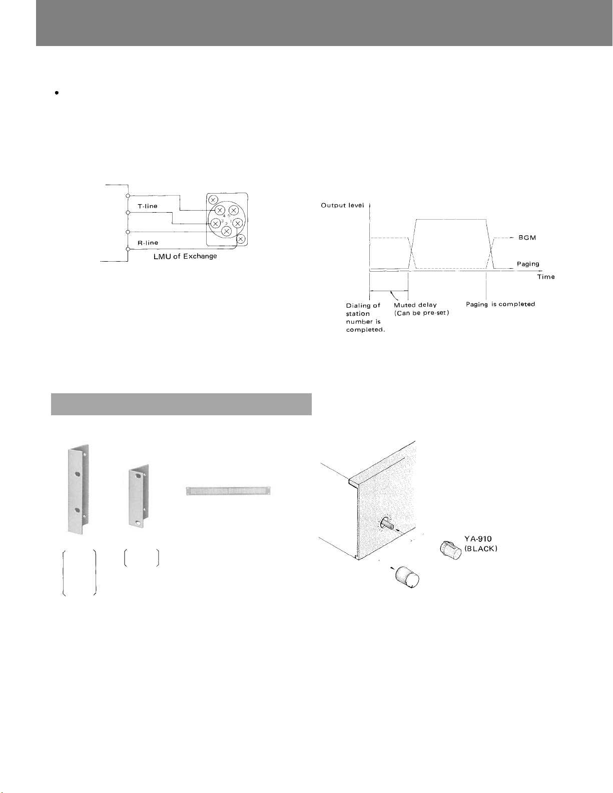
I-01S (BALANCED PAGING INPUT MODULE)
This module is used for connecting TOA intercom Systems (EXES)
for paging. By connecting this module to the exchange in place of
an intercom station, paging is possible. It is provided with a presettable gain control. The I-01S is applicable to the TOA EXES1000, EXES-5000 and EX-16 Intercom Systems.
CONNECTIONS
LMU (Line Modem Unit)
This unit is composed of a modulator to receive signals from
stations, a demodulator to send signals to the station and a scanning
circuit.
Summary Specifications of R and T Lines
R-line: Approx. 9mA DC plus audio signals of +30dBm m ax.
T-line: Approx. 9mA DC
HOW TO
Paging is possible from other station by dialing the station number
assigned to this module. To prevent a calling tone from being
sounded through the paging speaker, the module is designed to
override paging output during a period of time that the calling tone
signal is transmitted. The length of time to mute the paging output
is adjustable between zero and three seconds. During paging,
background music (the input signal fed to E -11, X-11, L-11 or B-11
module) is muted.
USE:
Operational Accessories
Rack-mounting Brackets
MB-931A MB-921A
A-906A
A-912A
P-906A
P-912A
P-924
(Silver)
M-900A
A-903A
Perforated Panel
(Silver)
PF-911
Volume Control Cover
— 12 —
Page 13
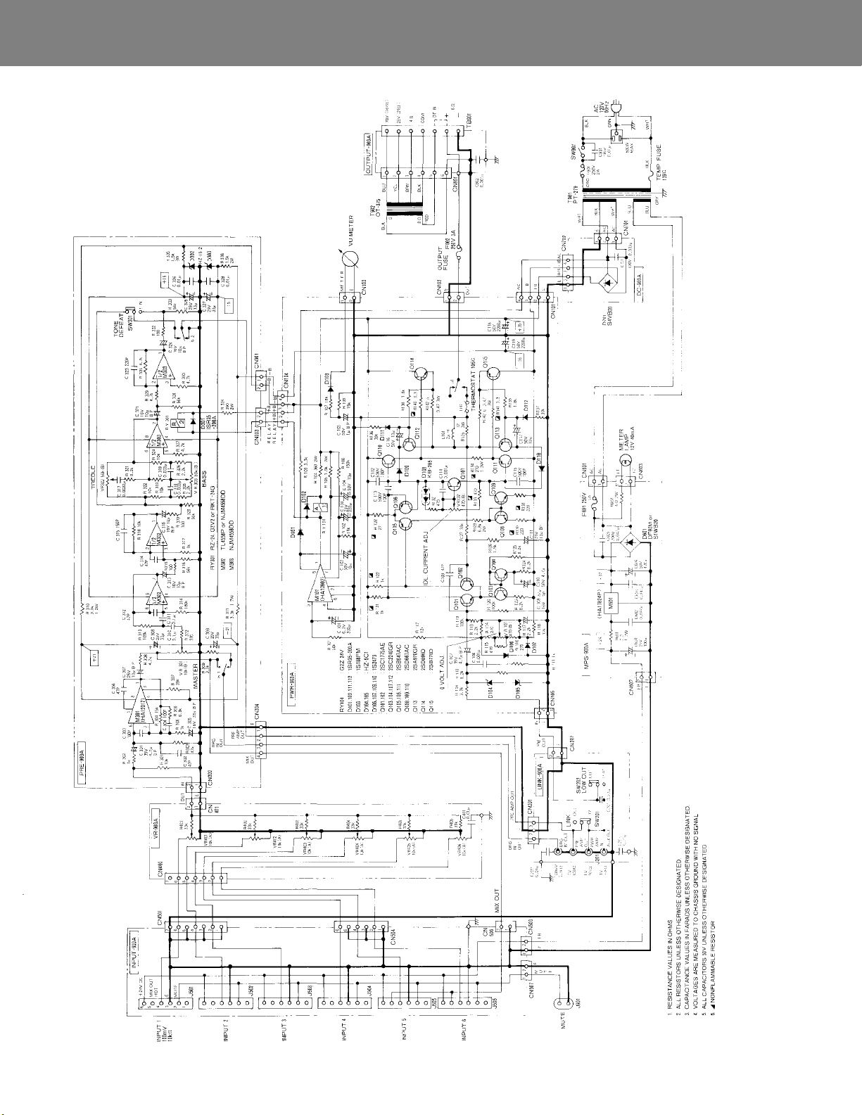
Schematic A-90 3A
— 13 —
Page 14
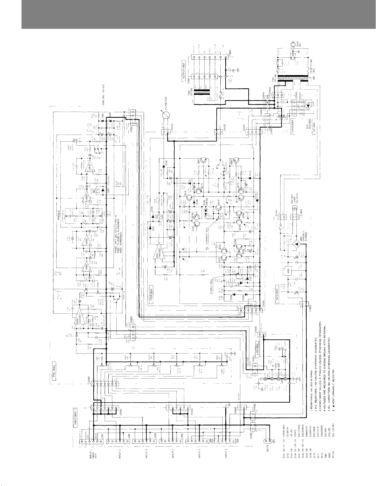
TOA NEW 900
SERIES
Schematic A-906A
— 14 —
Page 15
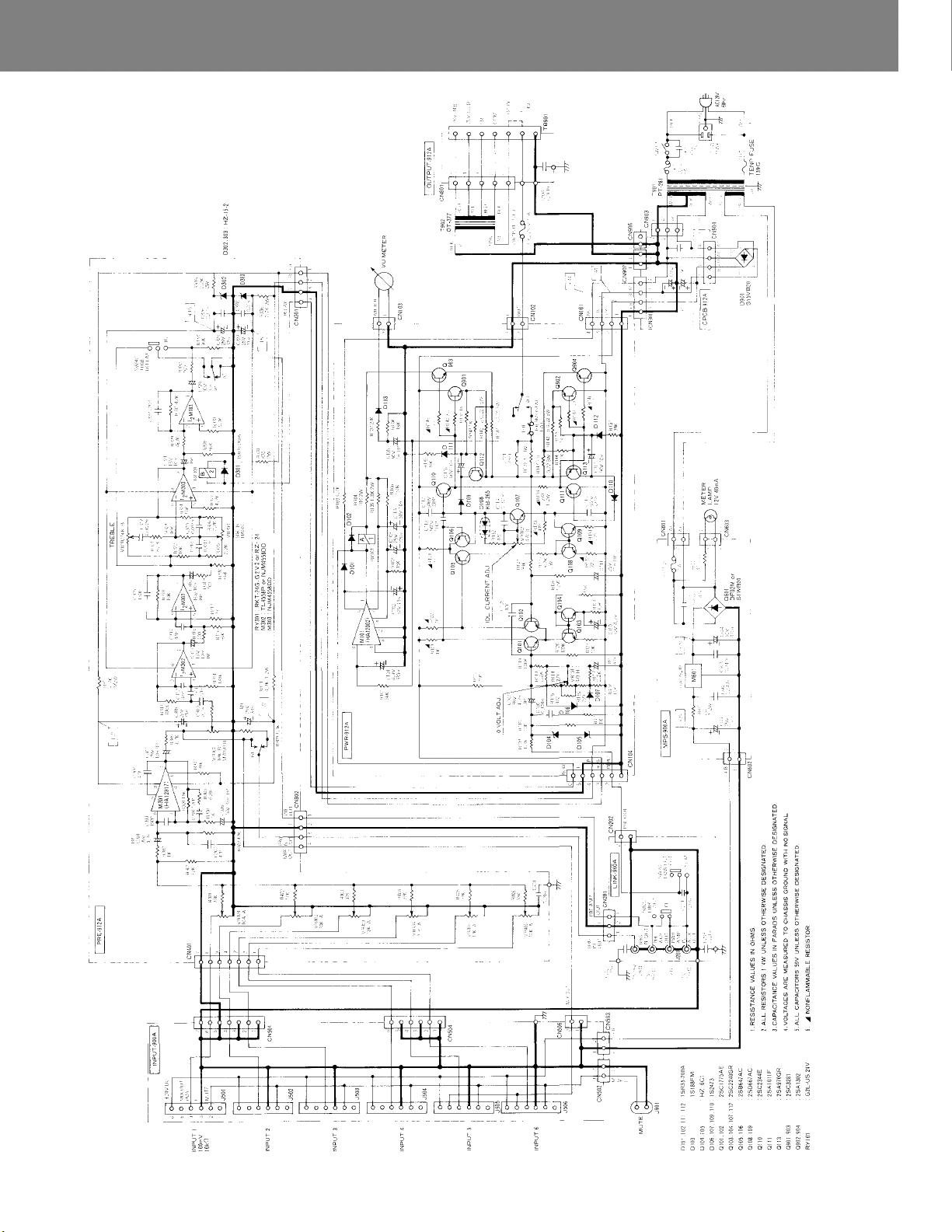
Schematic A-912A
 Loading...