

Page 1
STANDARD TRACK MOUNTING SYSTEMS
5 6
4” wide strips - 50% overlap
Hang the first strip with the blue stickers to the far left, skip 2”, hang
the second strip with the blue stickers, skip 2” and repeat to the far
right. Center the remaining strips with green stickers over 2” gaps.
4 - 50
6 - 33
6” wide strips - 33% overlap
Hang the first strip with the blue stickers to the far left, skip 4”, hang
the second strip with the blue stickers, skip 4” and repeat to the far
right. Center the remaining strips with green stickers over 4” gaps.
8” wide strips - 75% overlap
Hang the first strip with the blue stickers to the far left, skip 2” hang the
second strip with the blue stickers, skip 2” and repeat to the far right.
Center the remaining strips with green stickers over 2” gaps.
8 - 75
12 - 50
12” wide strips - 50% overlap
Hang the first strip with the blue stickers to the far left, skip 6” hang
the second strip with the blue stickers, skip 6” and repeat to the far
right. Center the remaining strips with green stickers over 6” gaps.
6” wide strips - 100% overlap
Hang the first strip with the blue stickers to the far left, align the second strip with the front strip, and repeat to the far right. Center the
remaining strips with green stickers over the seams.
6 - 100
8 - 25
8” wide strips - 25% overlap
Hang the first strip with the blue stickers to the far left, skip 6” hang
the second strip with the blue stickers, skip 6” and repeat to the far
right. Center the remaining strips with green stickers over 6” gaps.
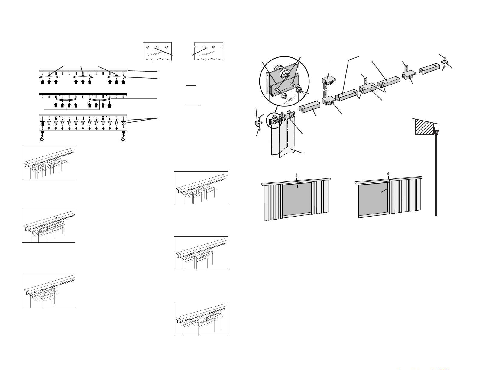
SPECIAL OVERLAP CONFIGURATIONS
Special overlaps use half of the strips with standard
holes and half off-set holes (see Fig. 4). Also, Blue
Stickers are used for the first row and Green Stickers
are used for the second row (see the illustration below).
•
•
Fig. 4
BLUE STICKERS
STICKERS
GREEN
STICKERS
Installed Mounting Bars
Place 1st row of strips on studs
with sticker away
from installer.
After 1st row is completed . . .
Place 2nd row of strips on studs
with sticker toward
the installer.
After 2nd row is completed . . .
Place retaining bars over studs,
attach lock-nuts and tighten.
If partial width strips are includ-
ed, see bottom illustration on
page 4.
STRAIGHT
TRACK
P. V.C. STRIPS
BI-PARTING WALL MOUNT
(BP-WM)
END
STOP
END
STOP
SECTIONAL HINGED
TROLLEY
WALL MOUNT TRACK
CONNECTOR – UP
WALL MOUNT
TRACK
CONNECTOR
– DOWN –
SPLICE CONNECTOR – UP
WALL MOUNT TRACK
CONNECTOR – UP
THREADED
STUDSRETAINING
BAR
NUT
NUT
NUT
BOLT
BOLT
MOUNTING
LUG
MOUNTING
LUG
SET
SCREWS
SET
SCREWS
STRAIGHT
TRACK
WALL MOUNT
SIDE VIEW PROFILE
STANDARD HOLES OFF-SET HOLES
Please study these drawings to familiarize yourself with part names and mounting methods.
ONE-SIDED WALL MOUNT
OS-WM
(Right side shown)
DOORWAY
CENTER
DOORWAY
EDGE
First, determine if your sliding door system is a bi-parting wall mount system (BPWM) or
a one-sided wall mount system (OSWM). If it is an OSWM system, you will also need to
determine to which side of the doorway opening the track will be extended (above illustration shows right-side extension). If you are not sure of which system you have purchased, please refer to the model number indicated on the front cover of this booklet.
FOR SINGLE TRACK (ONE PIECE) SYSTEMS
1. For BPWM models only, mark the center of the doorway opening.
2. Mark the center of the straight track section.
3. Loosely attach all wall mount track connectors to the straight track section. All the
connector’s anchor hole tabs should be in the up or down position, depending on
which connectors were shipped.
4. Position the far left connector 4” from the left end of the track and position the far
right connector 4” from the right end of the track. Then, evenly distribute the remaining connectors across the straight track section and tighten all the connectors.
5. Connect three hinged trolley sections and slide the trolley sections into one end of
the straight track.
Page 2
IMPORTANT
Carefully examine the carton(s) for damage.
If the carton is damaged, immediately notify the
shipping company.
YOUR MODEL NUMBER IS . . .
STRIP WIDTH STRIP OVERLAP TYPE OF HARDWARE
PLEASE READ ALL INSTRUCTIONS BEFORE
PROCEEDING WITH INSTALLATION.
7
INSTALLATION
INSTRUCTIONS
INSTALLATION
INSTRUCTIONS
❏ 4”
❏ 6”
❏ 8”
❏ 12”
❏ 16”
❏ 25%
❏ 33%
❏ 50%
❏ 67%
❏ 75%
❏ 100%
❏ SL
❏ UL
❏ UM
❏ BPWM
❏ OSWM
6. Place the end stops at both ends of the track.
7. Take one P.V.C. strip and temporarily attach the strip to the threaded studs on the
hinged trolley sections.
8. Raise and level the track assembly above the doorway opening, aligning the center
point of the track with the center point of the doorway opening (BPWM models) or the
center point of the track with the edge of the doorway opening (OSWM models).
Adjust until the bottom of P.V.C. strip is 1/2” above the floor.
9. Mark all the wall mount track connector mounting lug anchor holes and remove track
assembly.
10. Drill anchor holes and place anchors (supplied by others) into those holes.
11. Place anchors in each hole and attach the track assembly with lag screws.
12. Remove just one end stop from the assembly and slide the three hinged trolley sections with P.V.C. strip from the track assembly.
13. Connect and slide all of the individual hinged trolley sections into the open end of the
track assembly. The studs should be facing away from the wall.
14. Replace the end stop that was removed in step 12.
15. The final step is to attach the P.V.C. strips to the hinged trolley sections using one of
the three methods illustrated on pages 3, 4 and 5.
DOOR WIDTHS GREATER THAN 5’
Multiple tracks are used for these units and wall mount track splice connectors are utilized at the joints. If multiple tracks are required, they should be assembled in numerical
order from left to right. All joints must be aligned and butted together perfectly.
1. For BP-WM models only, mark the center of the doorway opening.
2. Lay out and assemble all track components on the floor at the base of the doorway.
All joints should be butted together tightly with splice connectors.
3. Attach all wall mount track connectors to the unit. All the connector’s mounting lugs
and splice connector’s mounting lugs should be in the up or down position, depending
on which units were shipped. Position the end connectors 4” from each end of the
track assembly.Then, evenly distribute the remaining connectors across the straight
track section and tighten all the connectors.
4. Measure and mark the center point of the track assembly and disassemble the
straight track sections at the splice joints.
5. Connect four hinged trolley sections and slide these sections into one end of the
straight track that has the marked center point.
6. With that one section, follow steps 7 through 10, “FOR SINGLE TRACK SYSTEMS”.
7. Using a level, attach the remaining track sections to the wall, one at a time, making
sure that each joint’s splice connector and track connectors are firmly attached to the
wall and the set screws are firmly tightened.
8. Once the assembly is completed, install one end stop.
9. Connect and slide all of the individual hinged trolley sections into the open end of the
track assembly. The studs should be facing away from the wall.
10. Install the remaining end stop.
11. The final step is to attach the P.V.C. strips to the hinged trolley sections using one of
the three methods illustrated on pages 4 and 5.
®
Catalog No. SD-II-06/07
©
Copyright 2007 TMI, LLC
Page 3

GETTING STARTED . . .
Open all carton(s) and remove all door hardware. Do not remove the P.V.C. strips
from the carton(s) until ready for installation.
NOTE: When multiple strip doors are ordered, all carton(s) will be properly
tagged.
All strip doors are shipped complete with the following:
• Mounting Bars (excluding support anchors)
• Retaining Bars, 1/4” strip fastening nuts and individual P.V.C. strips with
custom pre-punched holes
NOTE: Support anchors (provided by others) and mounting surface must be
capable of supporting the total weight of the strip door or the sliding strip
door. If you have any questions please refer to a registered architect or structural engineer.
Pre-studded galvanized steel Mounting Bars and Retaining Bars are standard
(aluminum and stainless steel optional). Depending on the door width, more than
one mounting bar might be supplied.
Wall Mount Hardware (SL)
The top edge of this steel hardware is
attached 4
3
/8” above the edge of the lintel, directly to the wall. Attach by conventional anchors or by welding (see Fig. 1).
Header Mount Hardware (UL
This steel hardware is attached directly to
the door header (lintel). Attach by conventional anchors or by welding (see Fig. 2).
Universal Hardware (UM)
The top edge of this steel hardware can
be attached 4
3
/8” above the edge of the
lintel, directly to the wall or can be
attached directly to the door header (lintel). Attach by conventional anchors or by
welding (see Fig. 3).
Sliding Track Hardware (BPWM or
OSWM)
Please refer to Page 6 for this type of
installation.
1 2
FIRST. . .
SECOND. . .
. . . determine which type of hardware and mounting procedure you will be
using by referring to YOUR MODEL NUMBER found on the front page of
this booklet. The checked boxes will let you know what strip width you
ordered, the percent overlap and the type of hardware & mounting procedure needed.
. . install the Mounting Bar(s) either on the wall above the doorway opening (WALL MOUNT)
or the under surface of the lintel (HEADER MOUNT). See Figures 1, 2 or 3.
Note: If multiple bars are required, start with Bar
➀
to the far left and continue to the
right in numerical order (
➁, ➂
, etc.). All joints must be aligned and butted together
perfectly.
Fig. 2
Fig. 1
Fig. 3
Retaining Bar
Header Mount (UL)
Header
Mount (UM)
Wall Mount (SL)
Wall
Mount (UM)
Retaining Bar
Retaining Bar
Mounting Bar
Mounting Bar
Mounting Bar
Doorway
Opening
P. V.C.
Strips
Mounting Bar
WALL MOUNT HARDWARE INSTALLATION (SL)
Pre-studded galvanized steel Mounting Bars and Retaining Bars are standard
(aluminum and stainless steel optional). Depending on the door width, more than
one mounting bar might be supplied.
HEADER MOUNT HARDWARE INSTALLATION (UM)
1. Temporarily attach a
P. V.C. strip to either
end of the Mounting
Bar(s).
2. Remove the Bar(s)
and drill the anchor
holes.
3. Place anchors in each
hole and attach the
Mounting Bar(s) with
lag screws.
2. Center and level the
bar(s) above the
opening so the strips
are 1/2” above the
floor.
3. Mark Mounting
Bar(s) anchor
holes and remove
the bar.
4. Drill anchor holes
and place anchors
(supplied by others)
into those holes.
5. Take the temporary
strips off the
Mounting Bar(s)
and attach the
Bar(s) with lag
screws.
1/2”
IMPORTANT
If attaching to wood, anchors are not
necessary. If attaching to steel, welding could be used.
1. Center the Mounting
Bar(s)on the underside of the lintel. Mark
the mounting holes.
SIDE VIEW
Centered
➀
➁➂
Align and Butt Joints Perfectly
Align and Butt Joints Perfectly
Page 4

. . . place the P.V.C. strips on the pre-studded hardware that has just been installed.
Before you start, refer to YOUR MODEL NUMBER found on the front page of this booklet to determine the width of your strips and overlap configuration.
3 4
THIRD. . .
STANDARD OVERLAP CONFIGURATIONS
Note: All strips are provided with a round colored sticker at the location of the
pre-punched holes. See SPECIAL OVERLAP diagrams on page 4.
Installed Mounting Bars
Installed Mounting Bars
Place 1st row of strips on studs with sticker
away
from installer.
After 1st row is Completed . . .
Place 2nd row of strips on studs with sticker
toward
the installer.
After 2nd row is completed . . .
Place retaining bars over studs, attach lock-
nuts and tighten.
Place 1st row of strips on
studs with sticker away
from
installer.
After 1st row is completed . . .
Place 2nd row of strips on
studs with sticker toward
the
installer.
After 2nd row is completed . .
.
Place retaining bars over
studs, attach lock nuts and
tighten.
STICKERS
STICKERS
STICKERS
STANDARD OVERLAP
STANDARD OVERLAP WITH SMALLER WIDTH END STRIPS
STICKERS
There are 3 overlap configurations used. The STANDARD OVERLAP (all strips are the
same width), the STANDARD OVERLAP WITH PARTIAL END STRIPS (one or two
strips are a smaller width and are placed at the ends) and SPECIAL OVERLAP (half the
strips have been specially punched and have a blue or green sticker affixed, see Page 5).
4” wide strips - 100% overlap
Hang the first strip to the far left, align the second strip with the first strip,
repeat to the far right. Center the remaining strips over the seams.
4 - 100
6 - 67
6” wide strips - 67% overlap
Hang the first strip to the far left, skip 2”, hang the second strip, skip 2” and
repeat to the far right. Center the remaining strips over 2” gaps.
16” wide strips - 25% overlap
Hang the first strip to the far left, skip 12”, hang the second strip, skip
12” and repeat to the far right. Center the remaining strips over 12”
gaps.
16 - 25
16 - 50
16” wide strips - 50% overlap
Hang the first strip to the far left, skip 8”, hang the second strip, skip
8” and repeat to the far right. Center the remaining strips over 8” gaps.
16” wide strips - 75% overlap
Hang the first strip to the far left, skip 4” , hang the second strip, skip
4” and repeat to the far right. Center the remaining strips over 4” gaps.
16 - 75
16 - 100
16” wide strips - 100% overlap
Hang the first strip to the far left, align the second strip with the first
strip. Repeat to the far right. Center the remaining strips over the
seams.
12” wide strips - 33% overlap
Hang the first strip to the far left, skip 8”, hang the second strip, skip 8”
and repeat to the far right. Center the remaining strips over 8” gaps.
12 - 33
12” wide strips - 100% overlap
Hang the first strip to the far left, align the second strip with first strip.
Repeat to the far right. Center the remaining strips over the seams.
12 - 100
12 - 67
12” wide strips - 67% overlap
Hang the first strip to the far left, skip 4”, hang the second strip, skip 4”
and repeat to the far right. Center the remaining strips over 4” gaps.
8” wide strips - 50% overlap
Hang the first strip to the far left, skip 4”, hang the second strip, skip 4” and
repeat to the far right. Center the remaining strips over 4” gaps.
8 - 50
8 - 100
8” wide strips - 100% overlap
Hang the first strip to the far left, align the second strip with the first strip.
Repeat to the far right. Center the remaining strips over the seams.
IMPORTANT: All P.V.C. strips have a natural curve across
the width of the material. When hung properly (row 1 concaved – row 2 convexed), it creates a barrier against drafts.
Row 1 - Concaved
Row 2 - Convexed
Draft Barrier Draft Barrier
SMALLER STRIPSMALLER STRIP
 Loading...