

Page 1
4
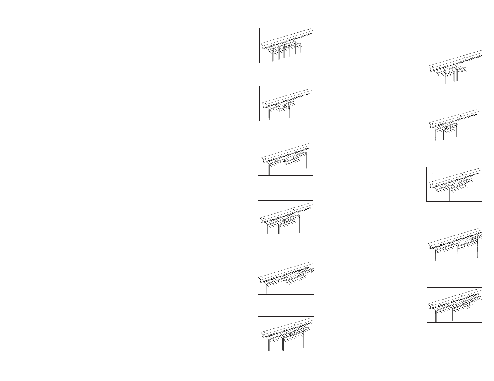
16” wide strips - 25% overlap
Hang the first strip to the far left, skip 12”, hang the second strip, skip 12”
and repeat to the far right. Center the remaining strips over 12” gaps.
16 - 25
16 - 50
16” wide strips - 50% overlap
Hang the first strip to the far left, skip 8”, hang the second strip, skip 8”
and repeat to the far right. Center the remaining strips over 8” gaps.
16” wide strips - 75% overlap
Hang the first strip to the far left, skip 4” , hang the second strip, skip 4”
and repeat to the far right. Center the remaining strips over 4” gaps.
16 - 75
16 - 100
16” wide strips - 100% overlap
Hang the first strip to the far left, align the second strip with the first strip.
Repeat to the far right. Center the remaining strips over the seams.
12” wide strips - 33% overlap
Hang the first strip to the far left, skip 8”, hang the second strip, skip 8”
and repeat to the far right. Center the remaining strips over 8” gaps.
12 - 33
12” wide strips - 100% overlap
Hang the first strip to the far left, align the second strip with first strip.
Repeat to the far right. Center the remaining strips over the seams.
12 - 100
12 - 67
12” wide strips - 67% overlap
Hang the first strip to the far left, skip 4”, hang the second strip, skip 4”
and repeat to the far right. Center the remaining strips over 4” gaps.
4” wide strips - 100% overlap
Hang the first strip to the far left, align the second strip with the first strip,
repeat to the far right. Center the remaining strips over the seams.
4 - 100
6 - 67
6” wide strips - 67% overlap
Hang the first strip to the far left, skip 2”, hang the second strip, skip 2”
and repeat to the far right. Center the remaining strips over 2” gaps.
8” wide strips - 50% overlap
Hang the first strip to the far left, skip 4”, hang the second strip, skip 4”
and repeat to the far right. Center the remaining strips over 4” gaps.
8 - 50
8 - 100
8” wide strips - 100% overlap
Hang the first strip to the far left, align the second strip with the first strip.
Repeat to the far right. Center the remaining strips over the seams.
Page 2
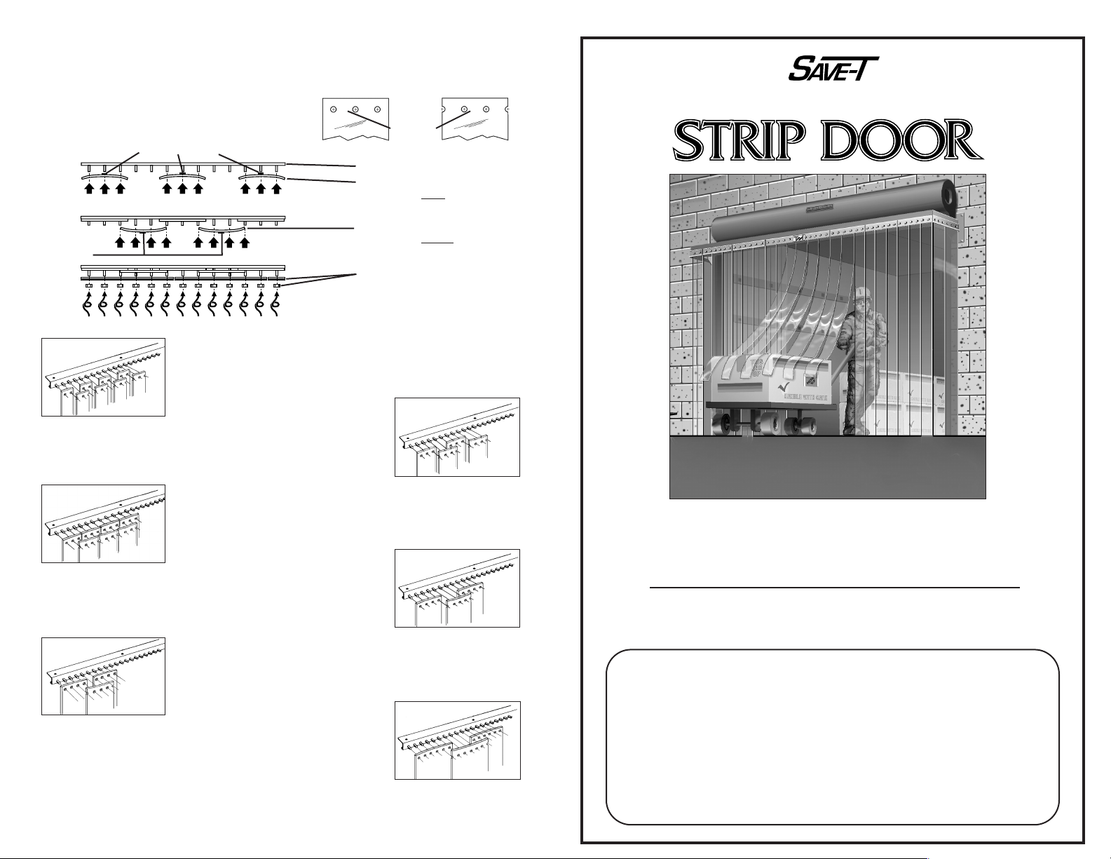
IMPORTANT
Carefully examine the carton(s) for damage.
If the carton is damaged, immediately notify the
shipping company.
YOUR MODEL NUMBER IS . . .
STRIP WIDTH STRIP OVERLAP TYPE OF HARDWARE
PLEASE READ ALL INSTRUCTIONS BEFORE
PROCEEDING WITH INSTALLATION.
5
INSTALLATION
INSTRUCTIONS
INSTALLATION
INSTRUCTIONS
❏ 4”
❏ 6”
❏ 8”
❏ 12”
❏ 16”
❏ 25%
❏ 33%
❏ 50%
❏ 67%
❏ 75%
❏ 100%
❏ H-ODB
❏ S-ODB
Catalog No. OHSD-II-06/07
4” wide strips - 50% overlap
Hang the first strip with the blue stickers to the far left, skip 2”, hang
the second strip with the blue stickers, skip 2” and repeat to the far
right. Center the remaining strips with green stickers over 2” gaps.
4 - 50
6 - 33
6” wide strips - 33% overlap
Hang the first strip with the blue stickers to the far left, skip 4”, hang
the second strip with the blue stickers, skip 4” and repeat to the far
right. Center the remaining strips with green stickers over 4” gaps.
8” wide strips - 75% overlap
Hang the first strip with the blue stickers to the far left, skip 2” hang
the second strip with the blue stickers, skip 2” and repeat to the far
right. Center the remaining strips with green stickers over 2” gaps.
8 - 75
12 - 50
12” wide strips - 50% overlap
Hang the first strip with the blue stickers to the far left, skip 6” hang
the second strip with the blue stickers, skip 6” and repeat to the far
right. Center the remaining strips with green stickers over 6” gaps.
6” wide strips - 100% overlap
Hang the first strip with the blue stickers to the far left, align the second strip with the front strip, and repeat to the far right. Center the
remaining strips with green stickers over the seams.
6 - 100
8 - 25
8” wide strips - 25% overlap
Hang the first strip with the blue stickers to the far left, skip 6” hang
the second strip with the blue stickers, skip 6” and repeat to the far
right. Center the remaining strips with green stickers over 6” gaps.
SPECIAL OVERLAP
Special overlaps use half of the strips with standard
holes and half off-set holes (see Fig. 1). Also, Blue
Stickers are used for the first row and Green Stickers
are used for the second row (see the illustration
below).
•
•
Fig. 1
BLUE STICKERS
STICKERS
GREEN
STICKERS
Installed Mounting Bars
Place 1st row of strips on studs
with sticker away
from installer.
After 1st row is completed . . .
Place 2nd row of strips on studs
with sticker toward
the installer.
After 2nd row is completed . . .
Place retaining bars over studs,
attach lock-nuts and tighten.
If partial width strips are includ-
ed, see bottom illustration on
page 4.
STANDARD HOLES OFF-SET HOLES
®
OVERHEAD
©
Copyright 2007 TMI, LLC
Page 3
GETTING STARTED. . .
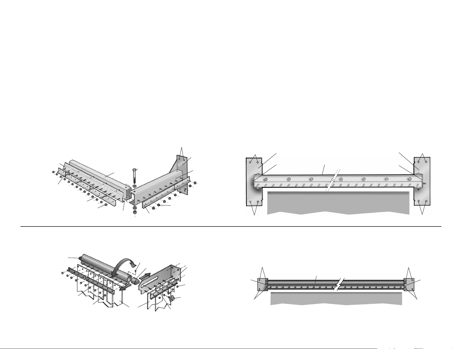
Open all carton(s) and remove all door hardware. Do not remove the PVC strips
from the carton(s) until ready for installation.
All strip doors are shipped complete with the following:
• 2 Wall mounting brackets (excluding wall support anchors)
• 1 Intermediate structural support tubing with pre-attached hardware
• 2 Bushings and bolts (S-ODB only)
• Retaining bars,
1
/4” strip fastening nuts and individual PVC strips with
custom pre-punched holes.
1 2
FIRST. . .
SECOND. . .
. . . determine that you have the proper wall mounting brackets.
Note: There are left and right hand brackets
. . . determine the correct mounting height and correct spacing of the wall brackets:
• Attach each bracket to the support tube.To assure proper bracket placement, the gusset
on the bracket should always face the door opening and the off-set side of the mounting
studs should face the floor.
• Temporarily attach 3 PVC strips, one on each mounting bracket gusset and one in center of the support tube.
• Raise and level the hardware and strips until the bottom of the strips are about
1
/2”
above the floor. Mark all mounting holes.
• Lower hardware and drill all pre-marked holes (4 holes of each mounting bracket).
• Remove individual strips from the brackets and support tube.
• Disassemble support tube from both mounting brakets.
• Install the brackets to the wall using the method the best suits your application (welding
could be applicable). Also, read “Note” below.
Retainer Bar
1/2”Hex Head Bolt
with Washer and
Hex Nut
#96 Hex Head Bolt
with Washer and
Hex Nut
1/4”Hex Nut
1/4”Hex Nut
1/4”Hex Nut
Retainer Bar
S.L. Hardware
Support
Tube
Structural
Tube
1/4”Hex Nut
Mounting
Bracket
Mounting
Bracket
Adjustable
Slide
Locking
Screw
PVC
Strip
Support Tube
with Pre-Attached
Studded Strip
Support Tube
with Pre-Attached
Studded Strip
Retainer Bar
Retainer Bar
Slider Retaining
Screw
STANDARD DUTY
Model S-ODB
HEAVY DUTY
Model H-ODB
• H-ODB
– 12” (10” inside projection)
– 18” (16” inside projection)
– 24” (22” inside projection)
• S-ODB
– 12” (6”-10” adjustable inside projection)
– 18” (10”-16” adjustable inside projection)
1/2”Mounting Holes
1/2”Mounting Holes
Mounting
Bracket
Gusset
Mounting
Bracket
Gusset
Mounting
Bracket
Gusset
1/2”Mounting Holes
1/2”Mounting Holes
1/2”Mounting Holes
Mounting
Bracket
Gusset
1/2”Mounting Holes
1/2”Mounting Holes
1/2”Mounting Holes
1/2”Mounting Holes
Mounting
Bracket
Gusset
Support Tube
DOORWAY OPENING
DOORWAY OPENING
Mounting
Bracket
Mounting
Bracket
Note: Support anchors and bolts (provided by others) and wall support struc-
ture must be capable of supporting the total weight of the strip door and hardware, as well as, additional force generated by the traffic through the door.
Page 4
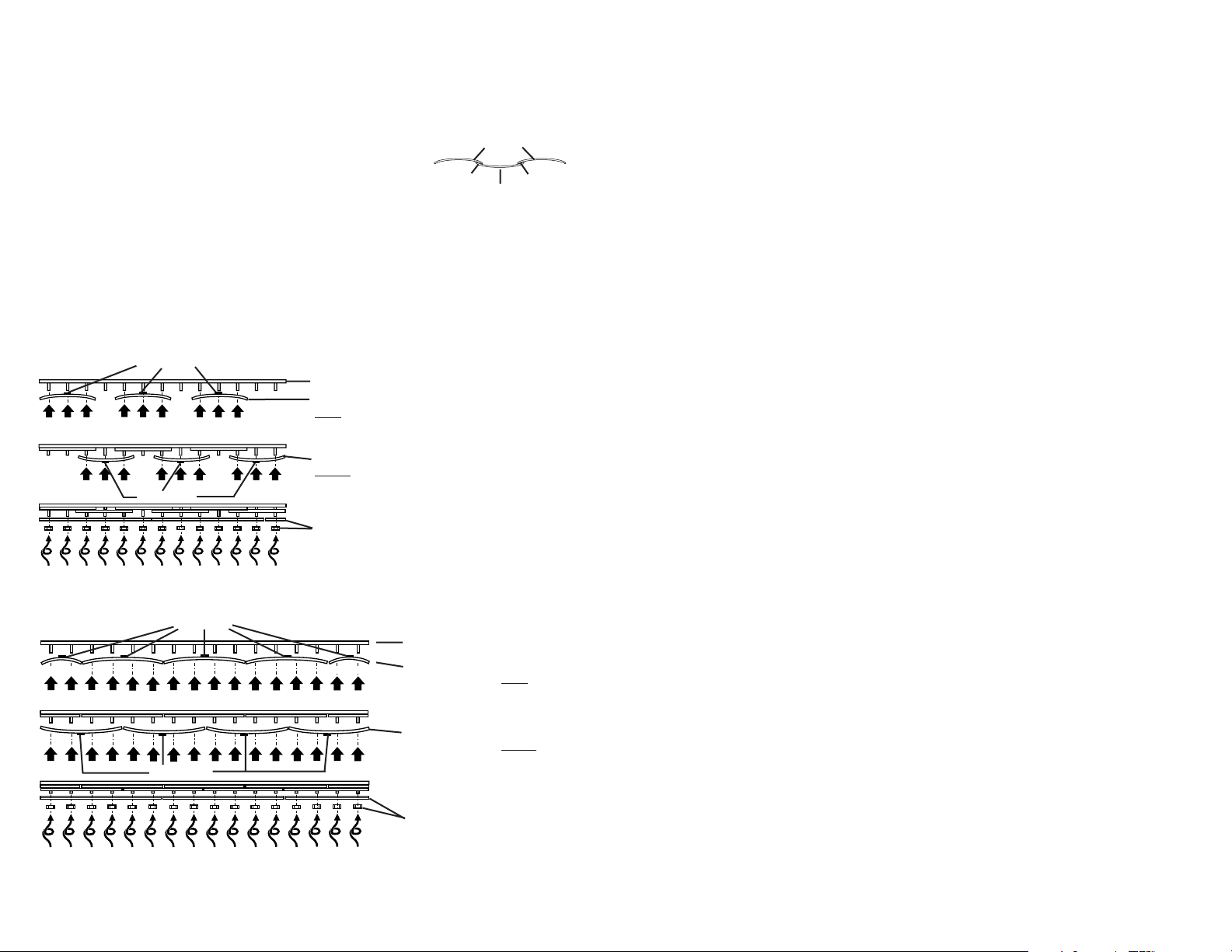
. . . place the PVC strips on the pre-studded hardware that has just been installed. Before
you start, refer to YOUR MODEL NUMBER found on the front page of this booklet to
determine the width of your strips and overlap configuration.
3
THIRD. . .
Note: All strips are provided with a round colored sticker at the location of the
pre-punched holes.
There are 3 overlap configurations used. The STANDARD OVERLAP (all strips are the
same width, see Page 3 & 4), the STANDARD OVERLAP WITH PARTIAL END STRIPS
(one or two strips are a smaller width and are placed at the ends, see Page 4) and
SPECIAL OVERLAP (half the strips have been specially punched and have green
stickers affixed, see Page 5).
IMPORTANT: All PVC strips have a natural curve across the
width of the material. When hung properly (Row 1 Concave –
Row 2 Convex), it creates a barrier against drafts.
Row 1 - Concave
Row 2 - Convex
Draft Barrier Draft Barrier
Installed Mounting Bars
Place 1st row of strips on studs with sticker
away
from installer.
After 1st row is completed . . .
Place 2nd row of strips on studs with sticker
toward
the installer.
After 2nd row is completed . . .
Place retaining bars over studs, attach lock-
nuts and tighten.
STICKERS
STICKERS
STANDARD OVERLAP
Installed Mounting Bars
Place 1st row of strips on
studs with sticker away from
installer.
After 1st row is completed . . .
Place 2nd row of strips on
studs with sticker to
ward
the
installer.
After 2nd row is completed . . .
Place retaining bars over
studs, attach lock nuts and
tighten.
STICKERS
STANDARD OVERLAP WITH SMALLER WIDTH END STRIPS
STICKERS
SMALLER STRIPSMALLER STRIP
 Loading...