

Page 1

Compact IP Codec
User's Manual
Version 1.0.6
Techno Mathematical Co., Ltd.
Page 2

Compact IP Codec User's Manual
1
Techno Mathematical Co., Ltd.
2140P
Prohibitions and Precautions during Use
Prohibitions
Doing something that is prohibited can cause malfunction of this Product.
Do not disassemble or modify.
Doing so creates the risk of electric shock.
Use only the provided AC adapter.
Using another adapter creates the risk of electric shock and fire.
Do not insert or pull out the power plug while your hands are wet.
Doing so creates the risk of electric shock.
Do not allow equipment to become wet.
Water or other liquid getting into the equipment creates the risk of electric shock
and fire.
Do not allow foreign objects to get into the unit.
Flammable or conductive objects getting into the equipment create the risk of
electric shock and fire.
Page 3

Compact IP Codec User's Manual
2
Techno Mathematical Co., Ltd.
2140P
Precautions
Use only the method described in this manual to turn power ON or OFF.
(Refer to Power ON/OFF.)
Using another method creates the risk of Product malfunction.
If you do not plan to use the Product for a long period, unplug it from the
power outlet.
Failure to do so creates the risk of electric shock and fire due to insulation
deterioration, electric leakage, etc.
Plug the power plug into an outlet as far as it will go.
Incomplete insertion creates the risk of electric shock and fire.
Do not do anything that can cause damage to the electric cord and plug.
(Do not pull on the cord, place heavy objects on it, locate it near a heating device,
etc.)
Continued use of a damaged power cord and/or plug creates the risk of electric
shock and fire.
Do not locate the Product in areas where there are large amounts of moisture
and/or dust, where it is exposed to oil smoke and/or steam, or near a heater.
Doing so creates the risk of electric shock and fire.
Do not locate the Product where it is exposed to direct sunlight.
Doing so creates the risk of Product deterioration and/or malfunction, and fire.
Do not use the Product in a location subject to sudden temperature changes,
which can cause condensation to form.
Doing so creates the risk of Product malfunction. Should condensation form on
the product, leave power turned off until it dries.
Do not locate the Product in an unstable location where there is the risk of
dropping due to vibration and/or impact.
Doing so creates the risk of personal injury.
Do not locate the Product in a location where strong magnetism is present.
Doing so creates the risk of Product malfunction.
Should you ever notice smoke, abnormal sound, strange odor, or other
abnormality, immediately stop using the Product.
Continued use of a Product exhibiting such abnormalities creates the risk of
electric shock and fire.
For the rear panel input ports, input only signals that conform to the
prescribed standards. (Refer to Product Specifications.)
Doing so creates the risk of Product malfunction.
Page 4

Compact IP Codec User's Manual
3
Techno Mathematical Co., Ltd.
2140P
Contents
1. Introduction ............................................................................................................. 7
Product Features .............................................................................................. 7
Main Features .................................................................................................. 7
2. Names of Parts and Functions ............................................................................... 8
3. Operation ............................................................................................................... 10
Operation Flow ............................................................................................... 10
Power ON/OFF ............................................................................................... 11
Operation from a PC ...................................................................................... 11
Controlling the Device with the Preset Switches ......................................... 11
4. Basic Settings ........................................................................................................ 12
Starting Up the Application Software ........................................................... 12
Basic Encoder Settings .................................................................................. 14
Basic Decoder Settings................................................................................... 18
5. Connecting an Encoder or Decoder ...................................................................... 20
When the Encoder has a Static IP ................................................................. 21
When the Decoder has a Static IP ................................................................. 28
When Neither the Encoder nor Decoder has a Static IP .............................. 31
5.3.1. Connection Example 1 ............................................................................ 35
5.3.2. Connection Example 2 ............................................................................ 36
6. Functions ............................................................................................................... 37
Repeater Function .......................................................................................... 37
Bidirectional Audio Call ................................................................................. 41
Auto Rate Control .......................................................................................... 44
6.3.1. Encoder Rate Control Operation Settings ............................................. 44
Rate Control Table Settings ........................................................................... 46
6.4.1. Decoder Rate Control Operation Setting ............................................... 48
7. Settings that Suit the Network Environment ..................................................... 49
Packet Length Setting ................................................................................... 49
Buffer Size Setting ......................................................................................... 50
Error Correction Settings .............................................................................. 51
Flatten Setting ............................................................................................... 53
8. Maintenance .......................................................................................................... 54
Setting File Download .................................................................................... 54
Setting File Upload ........................................................................................ 54
Firmware Update ........................................................................................... 55
9. Error and Warning Indicators .............................................................................. 56
Page 5

Compact IP Codec User's Manual
4
Techno Mathematical Co., Ltd.
2140P
Appendix 1. Errors and Warnings ............................................................................... 57
Appendix 2. Product Specifications ............................................................................. 61
Page 6

Compact IP Codec User's Manual
5
Techno Mathematical Co., Ltd.
2140P
Revision History
Version
Number
Date Description
0.8 2015/02/18
0.9 2015/03/03
• Initial default settings added for each setting item
• Mobile data communication card compatible wireless LAN
router connection added
• In connection diagrams 5.1. to 6.1., changed "Static IP" to
"Static global IP"
• Changed "static IP server" to "IP server."
• Added precautions for bidirectional audio communication
• Deleted entry about Dummy packet settings
• Changed error and warning list log output items to actually
output notation
1.0.0 2015/03/30
• Modified some preset switch setting contents
• Added and deleted error and warning list items
• Replaced remote application images to the latest versions
1.0.1 2015/06/08
• Made all kilo unit symbols lower case (k)
• Deleted "Audio Input" from encoder basic settings
• Deleted "Mode" entry
• Modified bidirectional audio communication connection diagram
• Added new flatten mode
1.0.2 2015/07/10
• Changed "Packet Settings" preset switch command to
"Advanced Settings," and added bidirectional audio
communication contents
1.0.3 2015/08/25
• Changed "IP circuit line network" and "IP line network" to
"Internet line network"
• Changed "system" to "device"
• Changed "transmission IP rate" and "IP rate" to "transmission rate"
• Changed "application" to "application software"
• Added reference positions to operation flow
• Changed description of operation using an application to
operation using a PC
• Changed "audio communication" to "phone call"
• Except for those in the appendix, added numbers to all tables
and figures
• Added preset switch command example
• Added normal connection explanation
Page 7

Compact IP Codec User's Manual
6
Techno Mathematical Co., Ltd.
2140P
1.0.4 2015/12/03
• Added 1280 x 720 and 720 x 480 to video input/output formats.
• Added copyright of OPUS.
1.0.5 2016/3/22 • Changed "preset switch" to "preset switch with LED "
• Deleted preset switch command example
• Added volume control to "Bidirectional Audio Call"
•
Added "Pro-MPEG" to "Error Correction Setting "
•
Added "program update"
1.0.6 2016/04/06
• Improved the quality of images.
• Modified captions.
• Chaneged “8. Preset Swicth Settings” to “8. Maintenance”.
Page 8

Compact IP Codec User's Manual
7
Techno Mathematical Co., Ltd.
2140P
1. Introduction
This Product uses standard Internet line network to transmit video and audio.
Product Features
High image quality at low bit rates
High-quality video and audio can be transmitted even over a 3G or other mobile
line.
Low latency
Transmission is possible with inter-device latency of approximately 100 ms.
Transmission with the same latency is also possible in a network environment.
(There may be some variation due to the network environment used.)
Practical functions
Optional functions are included to meet a variety of different needs: auto rate
control function, bidirectional audio communication function, repeater function,
and more.
Easy operation
Four preset switches on the front panel can be used to trigger preset functions.
Main Features
Table 1-1 Main Features
Transmission rate 64kbps to 3Mbps
Video input/output formats HDMI (TM7006E/TM7006D), HD-SDI (TM7007E)
1920 x 1080 60i/59.94i/30p/29.97p
1280 x 720 60p/30p
720 x 480 60i/59.94i/30p/29.97p
Automatically select
Video encoding bit rate 64kbps to 3Mbps
Video encoding frame rate 5fps/10fps/15fps/30fps (1080, 480)
10fps/20fps/30fps/60fps (720)
Audio input/output formats HDMI (TM7006E/TM7006D), HD-SDI (TM7007E)
16bit 48kHz PCM
Audio encoding sampling rate 24kHz/48kHz
Number of audio encoding
channels
None, 1ch., 2ch.
Audio encoding bit rate 32kbps/64kbps/128kbps/192kbps
For details, refer to "Appendix 2. Product Specifications."
Page 9
Compact IP Codec User's Manual
8
Techno Mathematical Co., Ltd.
2140P
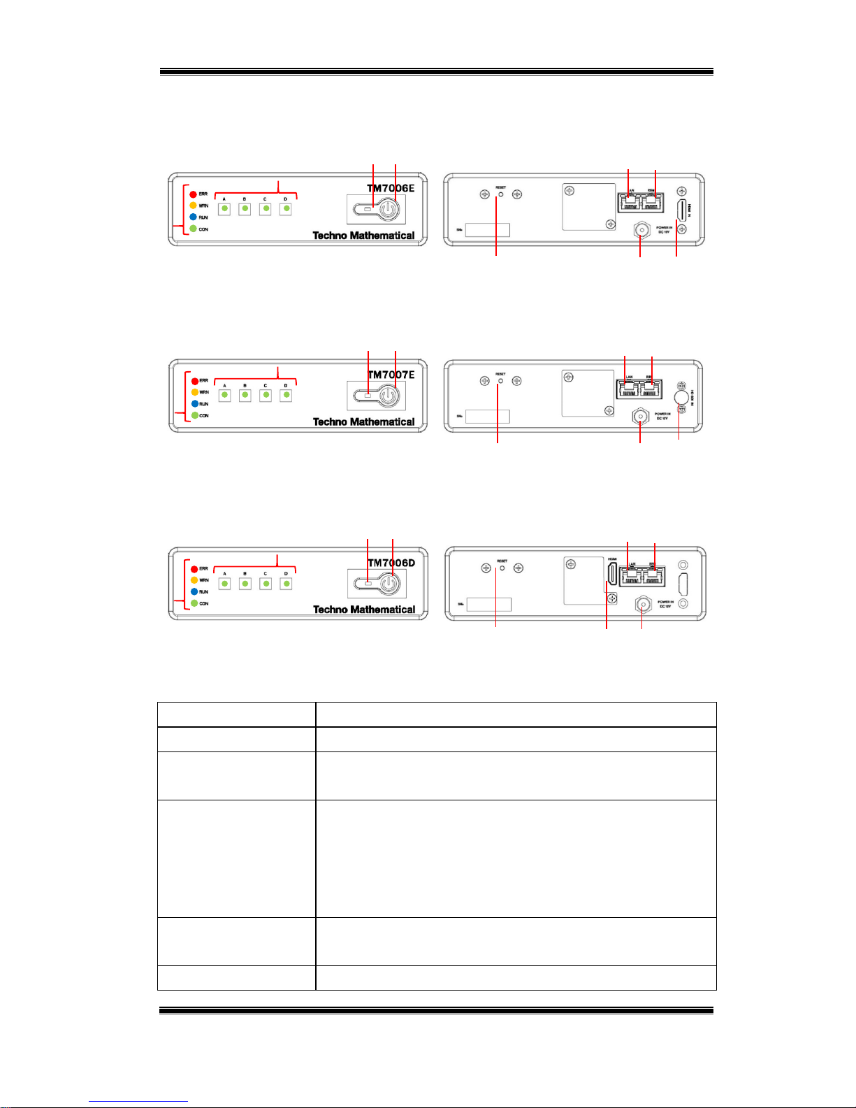
2. Names of Parts and Functions
TM7006E (encoder, HDMI input)
TM7007E (encoder, HD-SDI input)
TM7006D (decoder, HDMI output)
Table 2-1 Names of Parts and Functions
(1) Power switch
Turns power ON/OFF.
(2) Power lamp
Lit while power is on.
(3) Preset switches
Operations are assigned to each switch beforehand (From left to
right: A, B, C, D). When switch is pressed, Green LED is lit.
(4) Status indicators
LEDs that indicate the status of the device.
ERR (Lit red LED): Error WRN (Lit orange LED): Warning
RUN (Flashing blue LED):
Running
CON (Flashing green LED):
Transmitting data
(5) 12 VDC power
supply
Connect 12 VDC as power supply.
(6) LAN port
This Ethernet port transmits and receives image and audio
Front panel Rear panel
Front panel Rear panel
Front panel Rear panel
(8)
(6)
(5)
(9)
(7)
(12)
(4)
(3)
(1)
(2)
(8)
(6)
(5)
(10)
(7)
(12)
(4)
(3)
(1)
(2)
(8)
(6)
(5)
(11)
(7)
(13)
(4)
(3)
(1)
(2)
Page 10

Compact IP Codec User's Manual
9
Techno Mathematical Co., Ltd.
2140P
streams.
(7) Remote connection
port
This Ethernet port connects to the setup PC.
(8) Reset button
This button resets the Product to restart when an error is
generated, etc.
(9) HDMI input port
Inputs HDMI signals. (TM7006E)
(10) HD-SDI input port Inputs HD-SDI signals. (TM7007E)
(11) HDMI output port Outputs HDMI signals. (TM7006D)
(12) A USB port and HDMI port (disabled) is located under the cover. (TM7006E/7E)
(13) A USB port is located under the cover. (TM7006D)
(1) to (8) are common to all three models, while (9) through (13) are unique to each model.
Page 11
Compact IP Codec User's Manual
10
Techno Mathematical Co., Ltd.
2140P
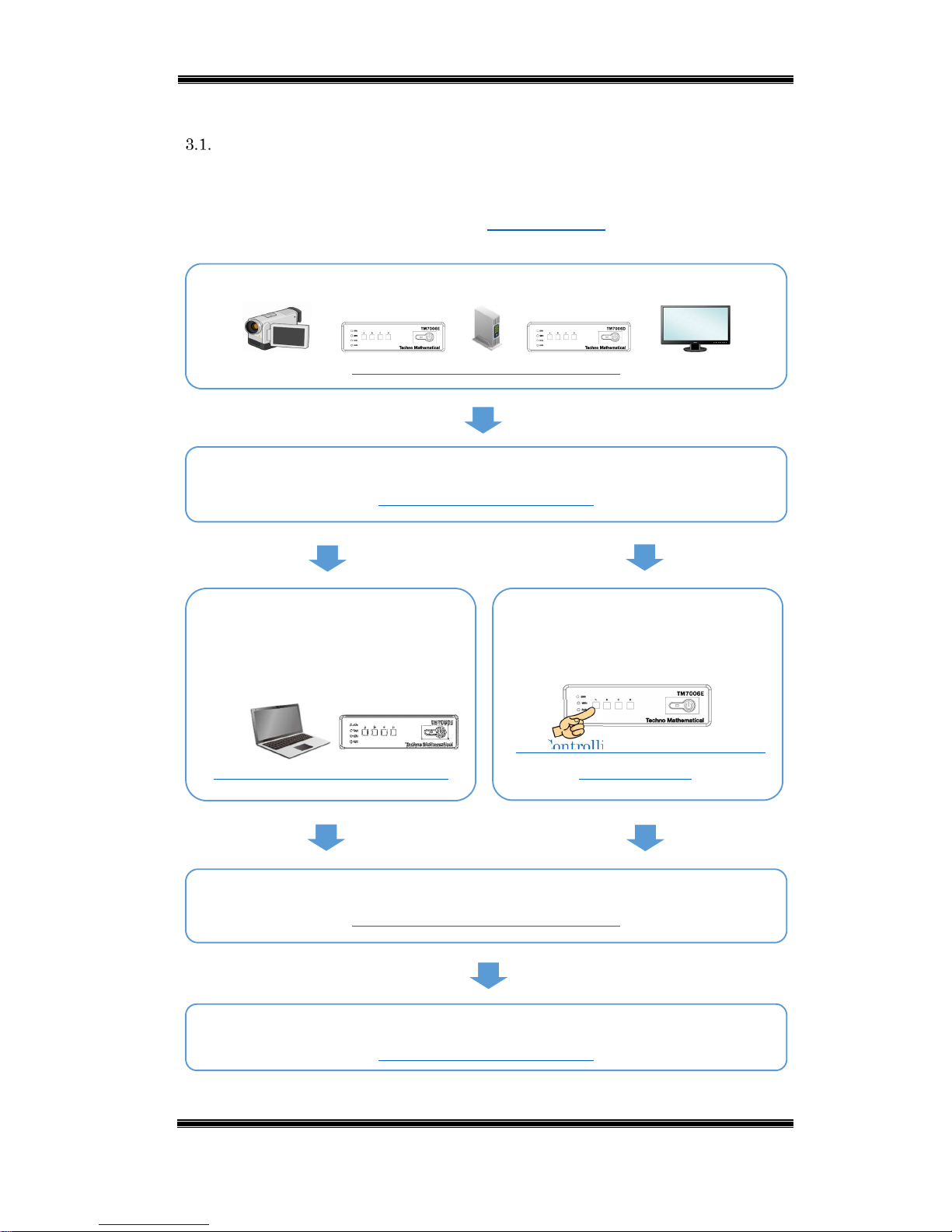
3. Operation
Operation Flow
The flow of basic operations is shown below.
*The first time the device is used or whenever network settings (device IP
address, etc.) are changed, configure 4. Basic Settings after (2).
(1) Connect the device and camera, monitor, router, and other peripherals.
(5. Connecting the Encoder or Decoder)
(2) Turn on the device and peripherals.
(3.2 Turning Power ON or OFF)
(3) Connect a PC to the device, and
perform operations and configure
settings on the PC using the
application.
(3.3 Controlling the Device from a PC)
(4) Perform operations and configure
settings from the device preset
switches.
(3.4 Controlling the Device with the
Preset Switches)
(5) Connect the encoder and decoder, and transmit video and audio.
(5. Connecting the Encoder or Decoder)
(6) After transmission is complete, turn off the device and peripherals.
(
3.2 Turning Power ON or OFF
)
Page 12

Compact IP Codec User's Manual
11
Techno Mathematical Co., Ltd.
2140P
Power ON/OFF
Power ON: After confirming that the rear panel DC power supply is connected,
press the front panel power switch. The power lamp will light. After about 40
seconds the RUN LED (blue) will flash.
Power OFF: Press the front panel power switch. This will turn off power and
cause the power lamp and LEDs to go out.
Operation from a PC
After connecting this device to the setup PC, device operation and setting
configuration can be performed from the setup PC. Download the application
software from the same download site where you downloaded this User's Manual.
Controlling the Device with the Preset Switches
Operations (destination settings, rate control settings, etc.) are assigned to each of
four switches beforehand. TMC can also configure desired settings for you.
Initial default settings are shown in the table below.
Table 3-1 Initial Default Settings of Preset Switches
Switch A Switch B Switch C Switch D
Encoder
Transmission
rate
3Mbps
Transmission
rate
1Mbps
Transmission
rate
128kbps
Rate Control
ON
Decoder
Connection
request to
encoder
192.168.100.101
Connection
request to
encoder
192.168.100.102
Rate Control
OFF
Rate Control
ON
Page 13

Compact IP Codec User's Manual
12
Techno Mathematical Co., Ltd.
2140P
4. Basic Settings
Configure the settings of this device from the application running under Windows.
Download the application software from the same download site where you
downloaded this User's Manual.
Starting Up the Application Software
To install the application software, execute the RemoteCtrl_nn.msi (nn: version
number) file you downloaded. After installation is complete, there will be two
icons on the PC desktop: ENCODER and DECODER.
Turn on the device.
Use LAN cable to connect the setup PC and the device remote connection port.
A network hub (with at least three ports) and three LAN cables can be used to
configure encoder and decoder settings simultaneously.
Set the PC IP address to match the remote connection IP address of the device.
The initial default settings of the IP addresses for device remote connection are
192.168.199.3 for the encoder and 192.168.199.4 for the decoder, so set the IP
address of the setup PC within the range of 192.168.199.1 to 255 (excluding
192.168.199.3 and 192.168.199.4).
• Open Control Panel.
• Click in the following sequence: Network and Internet → Network and Sharing Center
→ Change adapter settings.
• Right-click the icon of the network whose setting you want to change and then click
[Properties].
• Select Internet Protocol Version 4 (TCP/IPv4) and then click [Properties].
• Click Advanced Settings and then click [Add].
• Enter an IP address (such as: 192.168.199.1) and subnet mask (such as: 255.255.255.0)
and then click [Add].
Configuring the PC IP Address Setting
Hub
Encoder
Decoder
PC
Figure 4-1 Connect the Setup PC and the Device
Page 14

Compact IP Codec User's Manual
13
Techno Mathematical Co., Ltd.
2140P
Click ENCODER to configure encoder settings, or DECODER for decoder settings.
ENCODER
DECODER
Figure 4-2 Application Software Icons
Under initial default settings, select Default and then click [Connect].
Figure 4-3 Select Connection IP and Port
*If you changed the remote connection IP address and port number using the
procedures under "4.2. Basic Encoder Settings" or "4.3. Basic Decoder Settings,"
click [Add] and then add the changed values. Remarks can be left blank.
*An error message will appear if connection is not possible due to IP address
mismatch.
The screens shown below will appear following startup. From here on,
explanations will be based on these screens.
Figure 4-4 Screen After the Connection
To exit the application software, click the close button ([x]) in the upper right
corner.
Page 15

Compact IP Codec User's Manual
14
Techno Mathematical Co., Ltd.
2140P
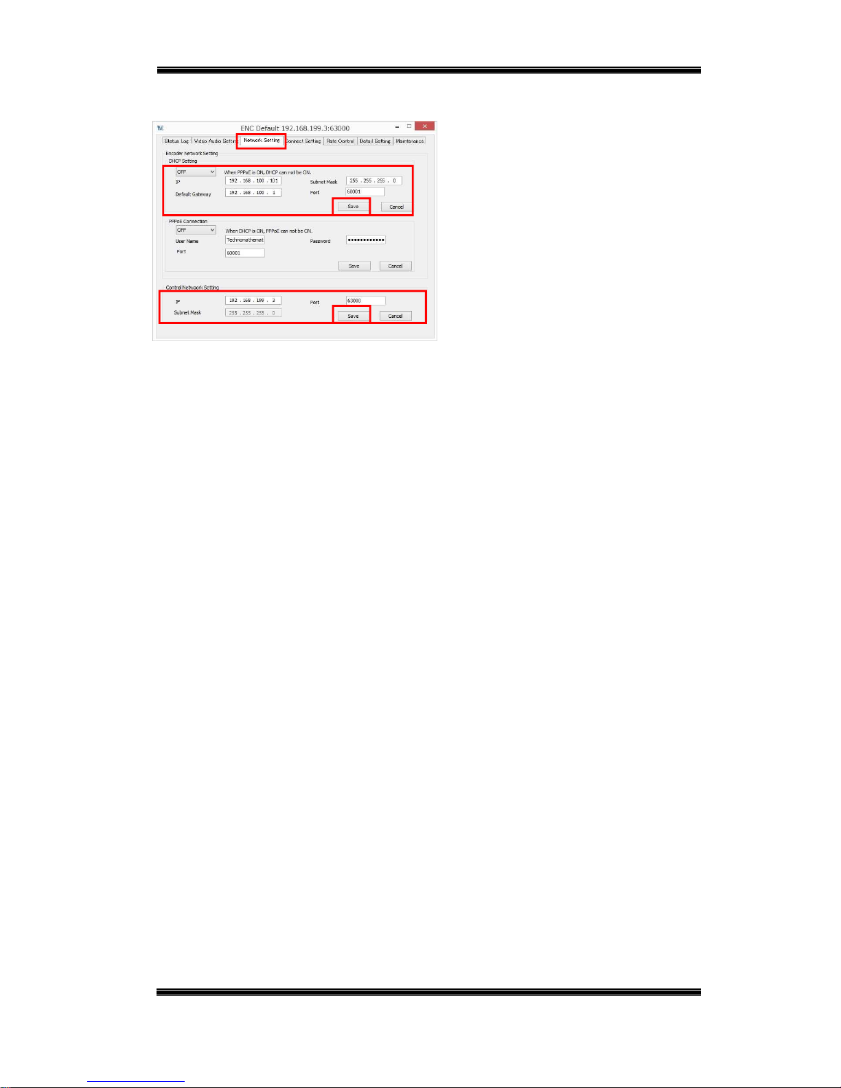
Basic Encoder Settings
(1) Configure the settings below in accordance with the network environment being
used.
A. For video and audio stream transmit/receive (LAN port)
Table 4-1 Encoder – LAN Initial Default Setting
Setting Description Initial Default
DHCP Set to ON when connected to a router that
supports DHCP, and to OFF to use a static IP
address.
OFF
IP Address When DHCP is OFF, sets the static IP address.
(000.000.000.000 to 255.255.255.255)
192.168.100.101
Subnet Mask When DHCP is OFF, sets the subnet mask.
(000.000.000.000 to 255.255.255.255)
255.255.255.0
Default
Gateway
When DHCP is OFF, sets the default gateway.
(000.000.000.000 to 255.255.255.255)
192.168.100.1
Port Sets the number of the port that
transmits/receives video and audio streams. (0 to
65535)
60001
B. For remote connection (remote connection port)
Table 4-2 Encoder – REM Initial Default Setting
Setting Description Initial Default
IP Address Sets the IP address for remote connection.
(000.000.000.000 to 255.255.255.255)
192.168.199.3
Port Sets the port number for remote connection.
(0 to 65535)
63000
Page 16
Compact IP Codec User's Manual
15
Techno Mathematical Co., Ltd.
2140P
Figure 4-5 Encoder – Network Setting
■ Start up ENCODER.
■ On the Network Setting tab, configure
the settings below.
A. For video and audio stream
transmit/receive
B. For remote connection
■ Be sure to click [Save] after
configuring settings.
A
B
Page 17

Compact IP Codec User's Manual
16
Techno Mathematical Co., Ltd.
2140P
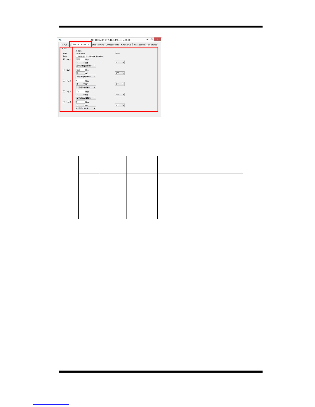
(2) Settings for encoding are described in the table below.
Table 4-3 Settings for Encoding
Setting Description
IP Rate Sets the transmission rate*1 within the range of 64 kbps to
3000 kbps.
Frame Rate Video frame rate setting: 5, 10, 15, 30 fps
Flatten Sets the transmission packet flattening*2 mode (OFF,
LowDelay, Quality, Double, 2Frame, 3Frame).
For details, refer to "7.4Flatten Setting."
CH Number
/Bit rate
/Sampling rate
Configures the settings of a group consisting of the number of
audio channels, bit rate, and sampling rate as a group.
0ch/0kbps/0kHz
1ch/16kbps/24kHz 1ch/32kbps/24kHz
1ch/32kbps/48kHz 1ch/64kbps/24kHz
1ch/64kbps/48kHz 1ch/128kbps/48kHz
2ch/32kbps/24kHz 2ch/64kbps/24kHz
2ch/64kbps/48kHz 2ch/128kbps/24kHz
2ch/128kbps/48kHz 2ch/192kbps/24kHz
2ch/192kbps/48kHz
*1
Transmission bit rate on the Internet line network
*2
Maintains a fixed transmission rate and does not exceed the rate setting.
Page 18
Compact IP Codec User's Manual
17
Techno Mathematical Co., Ltd.
2140P
Figure 4-6 Encoder – Video Audio Setting
■ On the Video Audio Setting tab,
configure settings.
■ After configuring the settings of five
groups, you can switch between the
groups by clicking the radio buttons on
the left.
Initial default settings are shown in the table below.
Table 4-4 Video Audio Setting – Initial Default Setting
IP Rate
(kbps)
Frame Rate
(fps)
Flatten
CH Number
/Bit Rate
/Sampling Rate
No.1 3000 30 OFF 2ch/192kbps/48kHz
No.2 1000 30 OFF 2ch/64kbps/24kHz
No.3 512 15 OFF 2ch/32kbps/24kHz
No.4 128 10 OFF 1ch/16kbps/24kHz
No.5 64 5 OFF 0ch/0kbps/0kHz
Page 19

Compact IP Codec User's Manual
18
Techno Mathematical Co., Ltd.
2140P
Basic Decoder Settings
Configure the settings below in accordance with the network environment being
used.
A. For video and audio stream transmit/receive (LAN port)
Table 4-5 Decoder – LAN Initial Default Setting
Setting Description Initial Default
DHCP Set to ON when connected to a router that
supports DHCP, and to OFF to use a static IP
address.
OFF
IP Address When DHCP is OFF, sets the static IP address.
(000.000.000.000 to 255.255.255.255)
192.168.100.160
Subnet Mask When DHCP is OFF, sets the subnet mask.
(000.000.000.000 to 255.255.255.255)
255.255.255.0
Default
Gateway
When DHCP is OFF, sets the default gateway.
(000.000.000.000 to 255.255.255.255)
192.168.100.1
Port Sets the number of the port that
transmits/receives video and audio streams. (0 to
65535)
60010
B. For remote connection (remote connection port)
Table 4-6 Decoder – REM Initial Default Setting
Setting Description Initial Default
IP Address Sets the IP address for remote connection.
(000.000.000.000 to 255.255.255.255)
192.168.199.4
Port Sets the port number for remote connection.
(0 to 65535)
63000
Page 20
Compact IP Codec User's Manual
19
Techno Mathematical Co., Ltd.
2140P
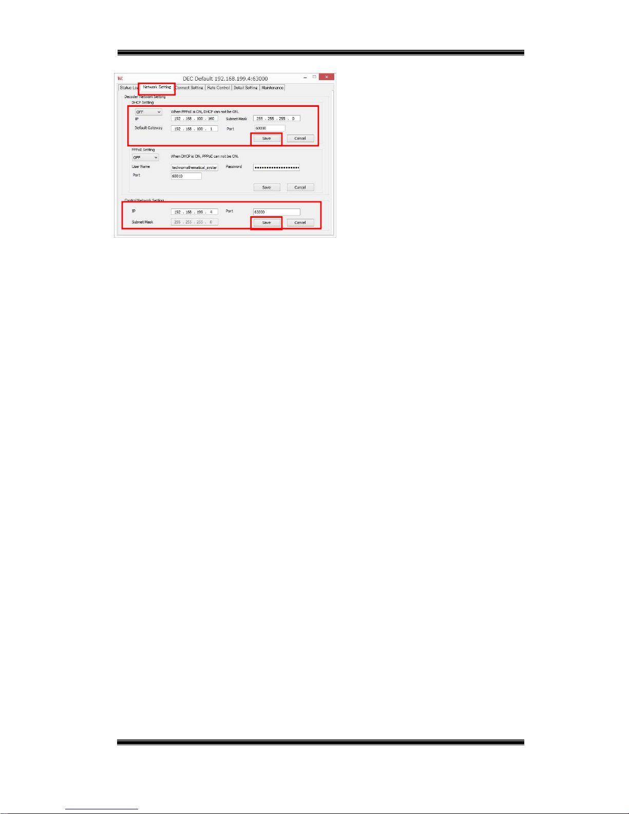
Figure 4-7 Decoder – Network Setting
■ Start up DECODER.
■ On the Network Setting tab,
configure the settings below.
A. For video and audio stream
transmit/receive
B. For remote connection
■ Be sure to click [Save] after
configuring settings.
A
B
Page 21

Compact IP Codec User's Manual
20
Techno Mathematical Co., Ltd.
2140P
5. Connecting an Encoder or Decoder
There are three basic ways to connect, each of which is described below.
"When the Encoder has a Static IP"
A stream is transmitted from the encoder in response to a connection request from
the decoder.
"When the Decoder has a Static IP"
A decoder is specified from the encoder and a stream is transmitted.
"When Neither the Encoder nor Decoder has a Static IP"
Connects via the server.
Basic Connection Methods
Page 22
Compact IP Codec User's Manual
21
Techno Mathematical Co., Ltd.
2140P
When the Encoder has a Static IP
A stream is transmitted from the encoder in response to a connection request from
the decoder. Up to 20 decoders can be simultaneously connected for each encoder. (In
this manual, this type of connection is referred to as a normal connection.)
Connection Diagram
Connection request from
the decoder to the encoder
LAN cable
HDMI cable
Encoder
Decoder
Decoder
Decoder
Internet
Setup PC
Camera
Monitor
Static global IP
Camera cable
Up to 20
units can
be connected at
the same time.
Page 23

Compact IP Codec User's Manual
22
Techno Mathematical Co., Ltd.
2140P
Encoder and decoder password verification is performed with this type of connection.
Verification will fail if the password sent from the decoder is not registered on the
encoder.
(1) Equipment Connection
Connect video output equipment to the encoder HDMI input (or HD-SDI input).
Connect video input equipment to the decoder HDMI output.
Connect the LAN ports of the encoder and decoder to the router. (If you want to
check operation without connecting to a network, directly connect the encoder
and decoder LAN ports to each other.)
Turn on the equipment.
(2) Encoder Settings
Connect the setup PC to the encoder remote port and configure the settings below.
Table 5-1 Normal Connection – Encoder Settings
Setting Description Initial Default
Password Sets a password that enables connection from
the decoder. (Up to 8 single-byte characters)
password
Remarks Remarks text (Up to 20 single-byte or 10
double-byte characters)
—
Connection Procedure
Page 24
Compact IP Codec User's Manual
23
Techno Mathematical Co., Ltd.
2140P
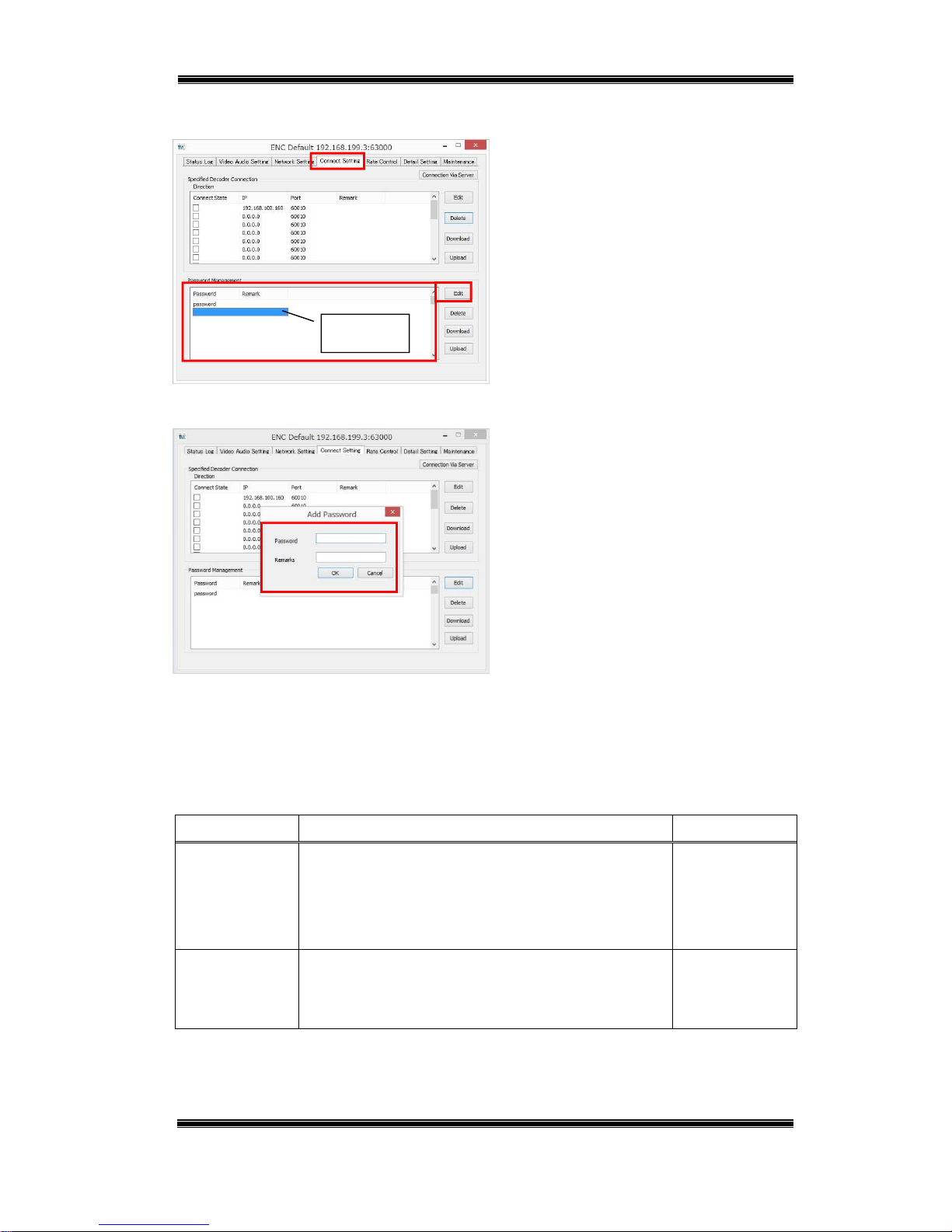
Figure 5-1 Encoder – Connect Setting
■ Start up ENCODER.
■ On the Connect Setting tab, select the
location in the [Password Management]
list where you want to add the password,
and then click [Edit].
Figure 5-2 Encoder – Add Password
■ Enter the password you want to set and
then click [OK].
*Remarks can be left blank.
(3) Decoder Settings
Connect the setup PC to the decoder remote port and configure the settings below.
Table 5-2 Normal Connection – Decoder Settings
Setting Description Initial Default
UserName Sets the user name. (Up to eight single-byte
characters)
When connected, the user name will be shown in
the encoder status.
user
Password Sets a connection password (the same password
registered on the encoder, up to eight single-byte
characters).
password
Select
Page 25
Compact IP Codec User's Manual
24
Techno Mathematical Co., Ltd.
2140P
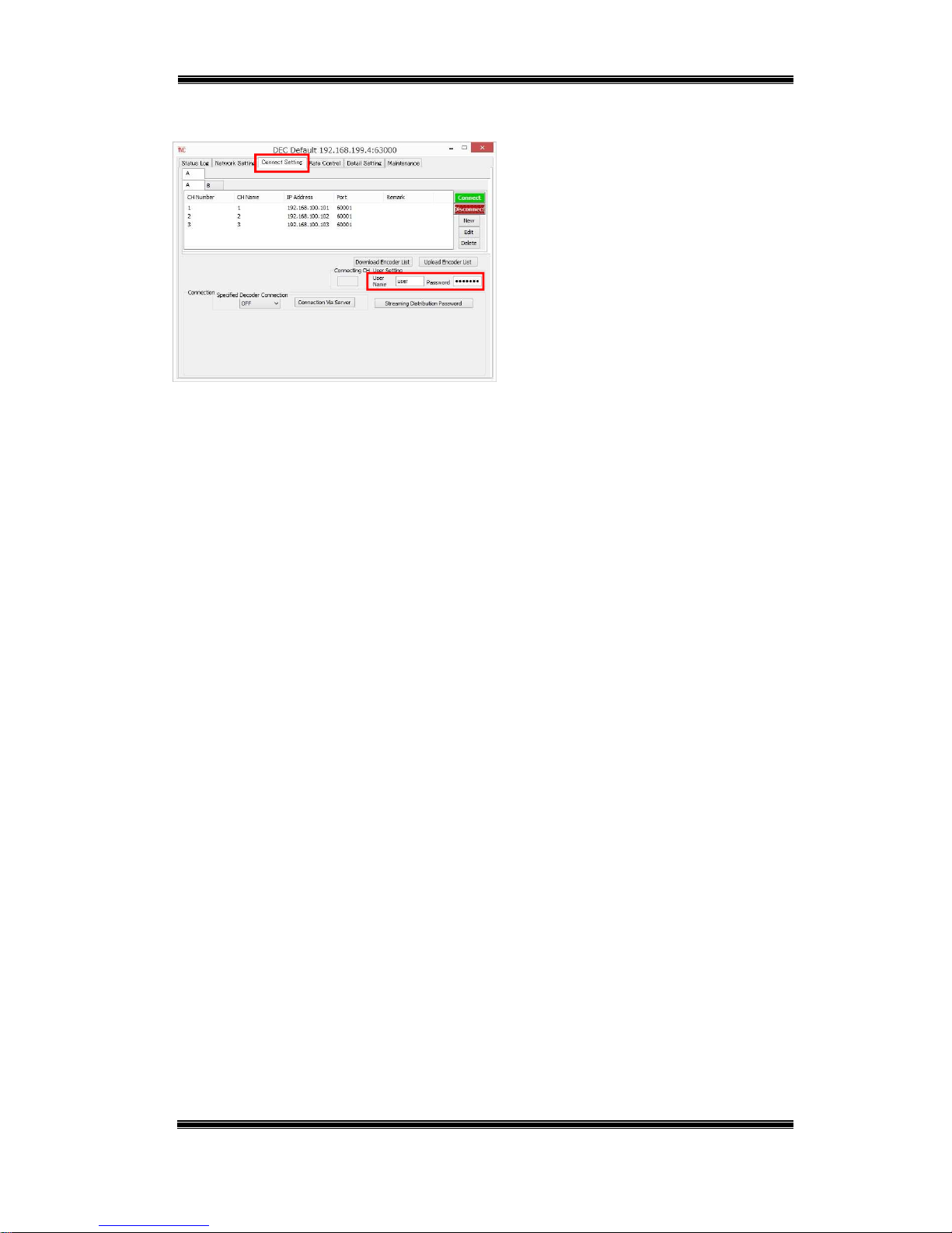
Figure 5-3 Decoder – Connect Setting
■ Start up DECODER.
■ On the Connect Setting tab, enter the
user name and password into the [User
Setting] text boxes.
Page 26

Compact IP Codec User's Manual
25
Techno Mathematical Co., Ltd.
2140P
Next, in the encoder list, register information about the encoder to which you want to connect.
Table 5-3 Encoder List Settings
Setting Description
CH Sets the encoder channel number. (1 to 9999)
CH Name Sets the encoder channel name. (Up to 10 single-byte characters)
IP Sets the encoder IP address.
Port Sets the encoder port number. (0 to 65535)
Remarks Remarks text (Up to 128 single-byte or 64 double-byte characters)
*The channel number (CH) and channel name (CH Name) are used by the decoder to
distinguish between encoders. These settings are not configured on an encoder.
Figure 5-4 Decoder – Add Encoder
■ On the Connect Setting tab, click
[New].
■ Enter the encoder information of the
encoder you want to connect and then
click [OK].
*Remarks can be left blank.
Figure 5-5 Decoder – Connect
■ Select the encoder you want to connect
and then click [Connect].
If the encoder and decoder passwords
match, connection will start.
Page 27

Compact IP Codec User's Manual
26
Techno Mathematical Co., Ltd.
2140P
Initial default settings for the encoder list are shown in the table below.
Table 5-4 Encoder List – Initial Default Setting
CH Number CH Name IP Address Port Remark
1 1 192.168.100.101 60001 —
2 2 192.168.100.102 60001 —
3 3 192.168.100.103 60001 —
Page 28

Compact IP Codec User's Manual
27
Techno Mathematical Co., Ltd.
2140P
(4) Status check
Encoder
Figure 5-6 Encoder – Status Log
■ You can use the Status Log tab to
check the connection status and settings.
■ For the encoder, the tab shows
currently connected decoders (up to 20)
and other information.
Decoder
Figure 5-7 Decoder – Status Log
■ For the decoder, the tab shows
information about the destination
encoder.
(5) Disconnect
Figure 5-8 Decoder – Disconnect
■ To disconnect, click [Disconnect] on
the decoder Connect Setting tab.
Page 29

Compact IP Codec User's Manual
28
Techno Mathematical Co., Ltd.
2140P
When the Decoder has a Static IP
A decoder IP address and port number are specified from the encoder, and a stream is
transmitted. Simultaneous transmission to up to 20 decoders is possible from each
encoder. (In this manual, this type of connection is referred to as a specified decoder
connection.)
Connection Diagram
Static
global IP
A decoder is specified from
the encoder for connection.
Camera cable
LAN cable
Encoder
Decoder
Decoder
Setup PC
Camera
Internet
Monitor
HDMI cable
Decoder
Up to 20 units can
be connected at
the same time.
Page 30

Compact IP Codec User's Manual
29
Techno Mathematical Co., Ltd.
2140P
(1) Equipment Connection
Connect video output equipment to the encoder HDMI input (or HD-SDI input).
Connect video input equipment to the decoder HDMI output.
Connect the LAN ports of the encoder and decoder to the router. (If you want to
check operation without connecting to a network, directly connect the encoder
and decoder LAN ports to each other.)
Turn on the equipment.
(2) Decoder Settings
Connect the setup PC to the decoder remote port and configure the settings below.
Figure 5-9 Decoder – Specified Decoder
Connection
■ Start up DECODER.
■ On the Connect Setting tab, select ON
for [Specified Decoder Connection].
(3) Encoder Settings
Connect the setup PC to the encoder remote port and configure the settings below.
Table 5-5 Specified Decoder Connection – Encoder Settings
Setting Description
Connect State Selecting a check box causes the stream to be transmitted to
that decoder.
Decoder IP Sets the transmission destination decoder IP address.
Decoder Port Sets the transmission destination decoder port number. (0 to
65535)
Remarks Remarks text (Up to 16 single-byte characters)
Connection Procedure
Page 31

Compact IP Codec User's Manual
30
Techno Mathematical Co., Ltd.
2140P
Figure 5-10 Encoder – Connect Setting
■ Start up ENCODER.
■ On the Connect Setting tab, select the
location in the [Specified Decoder
Connection] list where you want to add a
decoder, and then click [Edit].
Figure 5-11 Encoder – Add Decoder
■ Enter the information of the
transmission destination decoder and
then click [OK].
*Remarks can be left blank.
Figure 5-12 Encoder – Connect Status
Selecting a [Connect State] check box
causes the stream to be transmitted to
that decoder.
Leaving a check box selected
automatically transmits the stream to
that decoder when power is turned on.
Initial default settings are shown in the table below.
Table 5-6 Encoder – Specified Decoder Connection – Initial Default Setting
Connect State IP Port Remark
(Not selected) 192.168.100.160 60010 —
Select
Page 32
Compact IP Codec User's Manual
31
Techno Mathematical Co., Ltd.
2140P
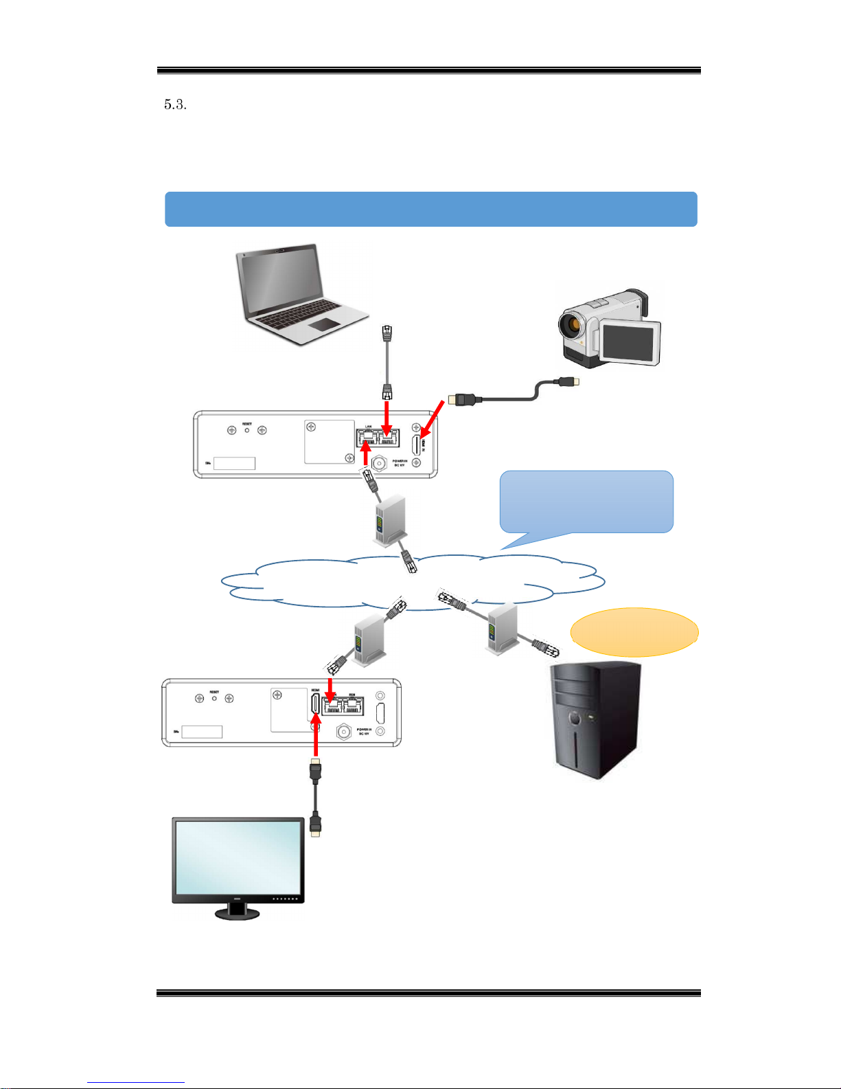
When Neither the Encoder nor Decoder has a Static IP
Connection is via a server with a static IP. The encoder and decoder will send their
own IP addresses and port numbers to the IP server, and then the IP server
establishes a connection based on the received information.
Connection Diagram
Connection via server
IP server
LAN cable
HDMI cable
Encoder
Decoder
Internet
Setup PC
Camera
Monitor
Camera cable
Static
global IP
Page 33

Compact IP Codec User's Manual
32
Techno Mathematical Co., Ltd.
2140P
(1) Equipment Connection
Prepare a server with a static IP.
Connect video output equipment to the encoder HDMI input (or HD-SDI input).
Connect video input equipment to the decoder HDMI output.
Connect the LAN ports of the encoder and decoder to the router.
Turn on the equipment.
Configure IP server information settings on the encoder and decoder.
Table 5-7 Connection via Server Settings
Setting Description Initial Default
ON/OFF Set to ON to use an IP server to connect. OFF
Server IP Address Sets the IP server IP address. 192.168.100.1
Server Port Sets the IP server port number. (0 to 65535) 62000
CH Sets the channel number. (1 to 9999)
(Sets the encoder's channel number on an
encoder, sets the destination encoder channel
number on a decoder.)
9999
Connection Procedure
Page 34
Compact IP Codec User's Manual
33
Techno Mathematical Co., Ltd.
2140P
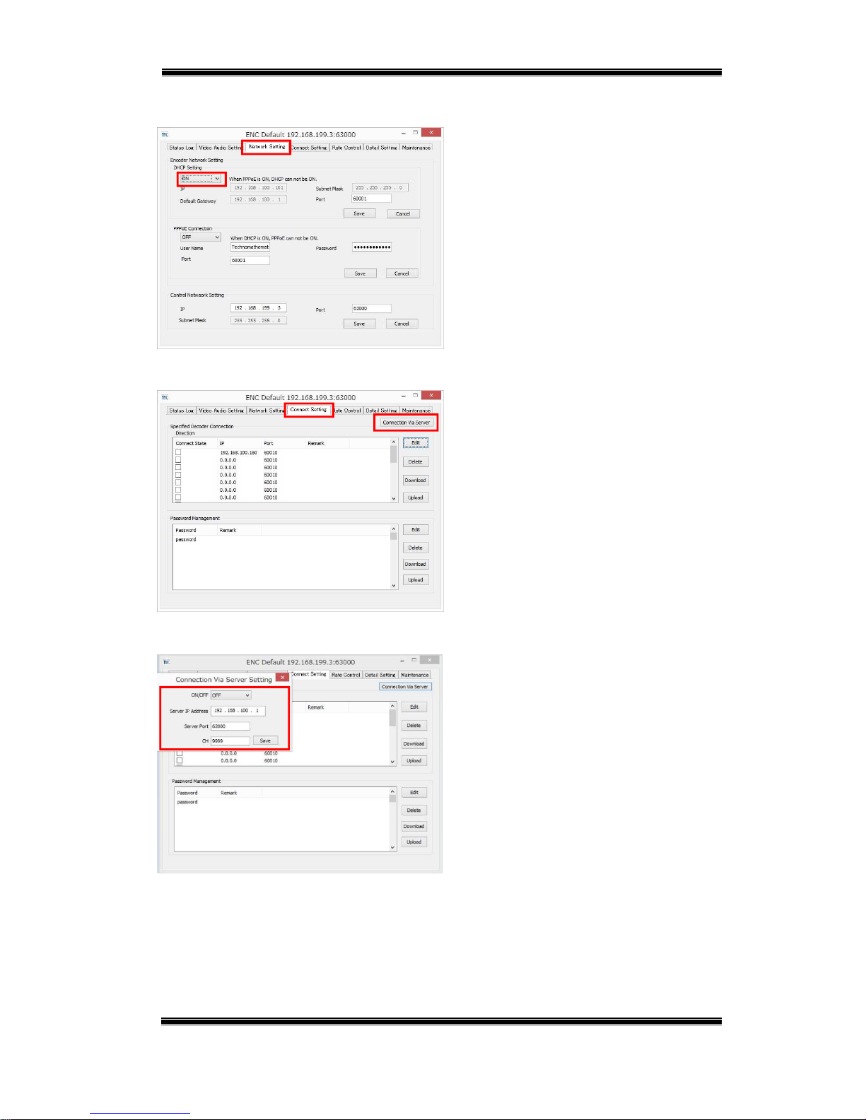
(2) Encoder Settings
Figure 5-13 Encoder – DHCP
■ Start up ENCODER.
■ On the Network Setting tab, select ON
for [DHCP Setting] in accordance with
the network environment being used, and
then click [Save].
Figure 5-14 Encoder – Connect Setting
■ On the Connect Setting tab, click
[Connection Via Server].
Figure 5-15 Encoder – Connection Via
Server
■ Select ON, enter server information,
and then click [Save].
Page 35
Compact IP Codec User's Manual
34
Techno Mathematical Co., Ltd.
2140P
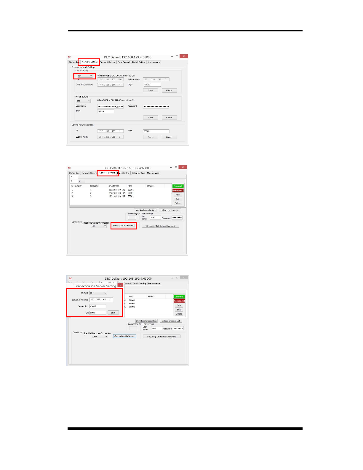
(3) Decoder Settings
Figure 5-16 Decoder – DHCP
■ Start up DECODER.
■ On the Network Setting tab, select
ON for [DHCP Setting] in accordance
with the network environment being
used, and then click [Save].
Figure 5-17 Decoder – Connect Setting
■ On the Connect Setting tab, click
[Connection Via Server].
Figure 5-18 Decoder – Connection Via Server
■ Select ON, enter server information,
and then click [Save].
Page 36
Compact IP Codec User's Manual
35
Techno Mathematical Co., Ltd.
2140P
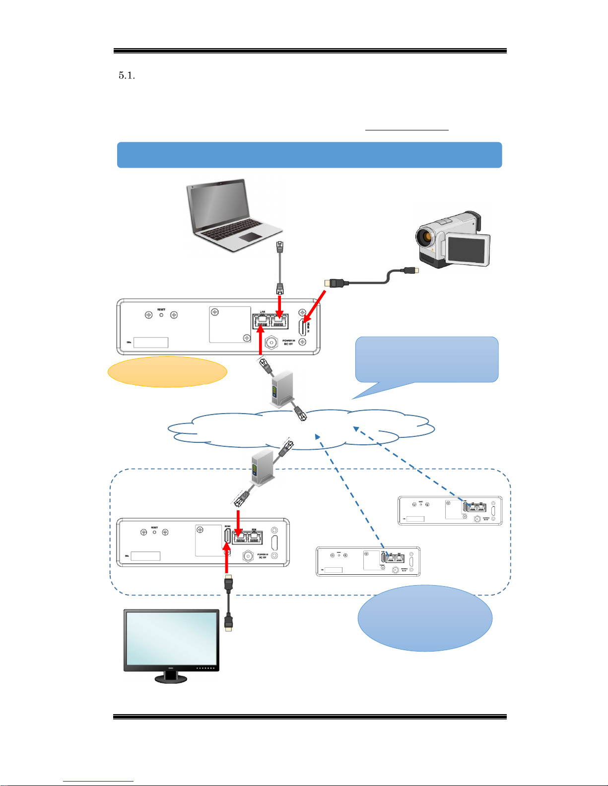
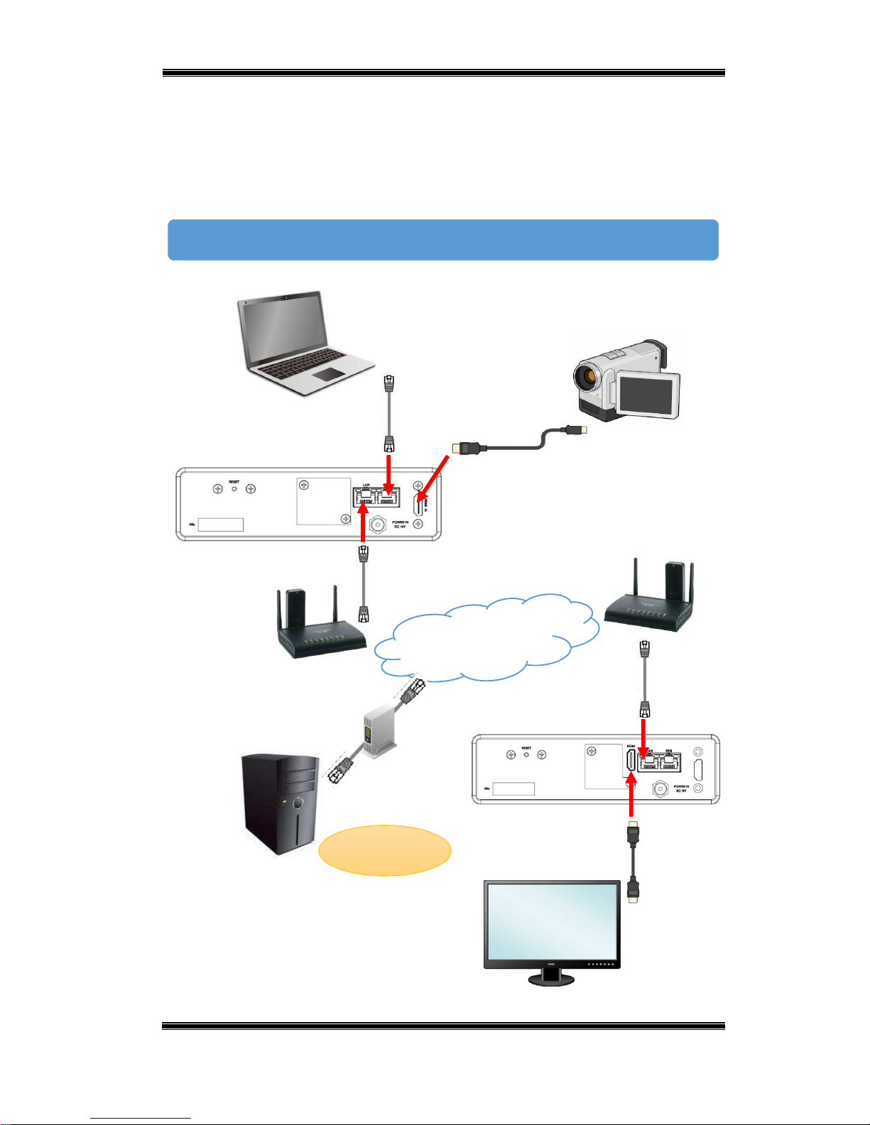
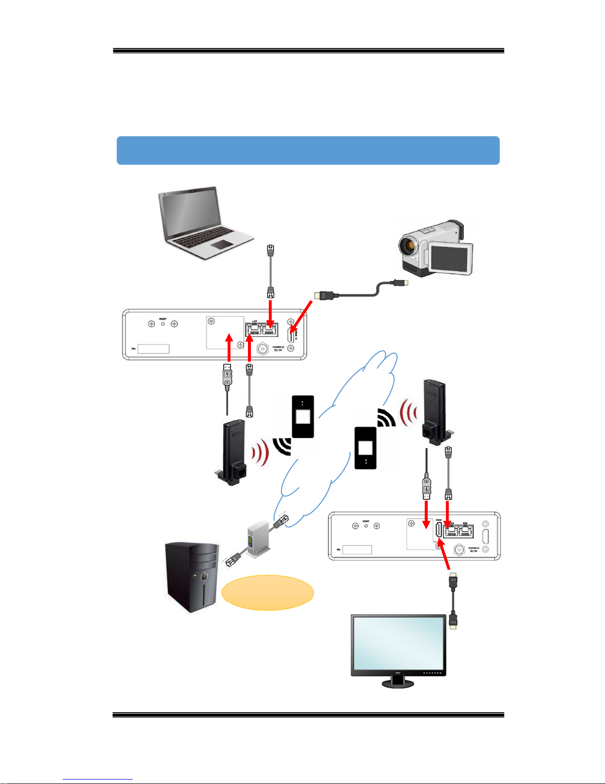
5.3.1. Connection Example 1
Connection is possible using a mobile data communication card compatible wireless
LAN router. TMC recommends use of a Micro Research MR-GM2 router. For the
MR-GM2 setup procedure and details about the connection procedure, see the
separate connection manual.
Connection Diagram
LAN cable
HDMI cable
Encoder
Decoder
Setup PC
Camera
Monitor
Camera cable
IP server
Static global
IP
Internet
MR-GM2 mobile data
communication card
MR-GM2 mobile data
communication card
Page 37
Compact IP Codec User's Manual
36
Techno Mathematical Co., Ltd.
2140P
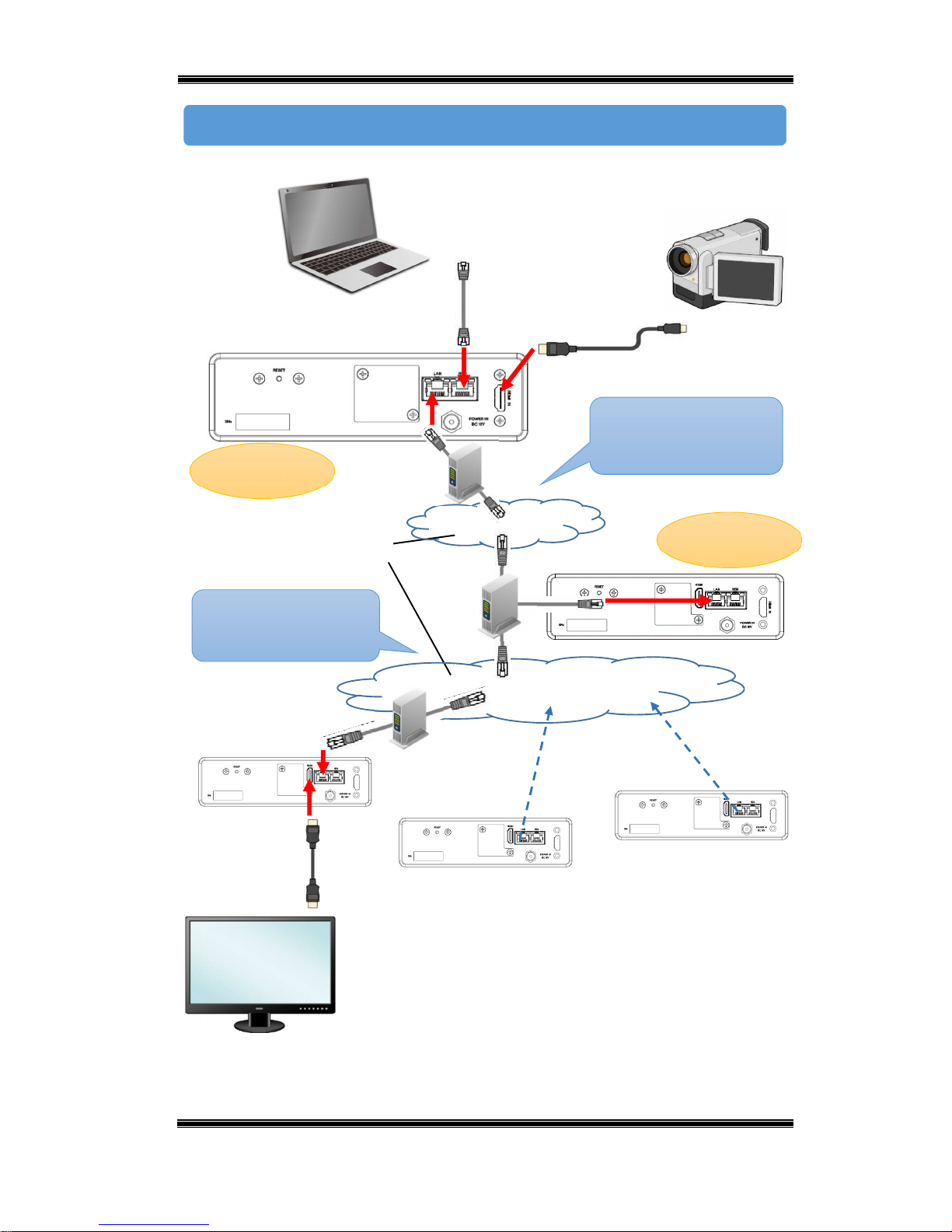
5.3.2. Connection Example 2
Connection is possible using a Wi-Fi mobile router and wireless LAN converter. For
the setup procedure, refer to the user documentation that comes with the devices
being used.
Connection Diagram
Wireless
LAN
converter
LAN cable
HDMI cable
Encoder
Decoder
Mobile router
Setup PC
Camera
Camera cable
Wireless
LAN
converter
Mobile router
IP server
Internet
Static global
IP
*A USB port is located under the rear panel cover.
The wireless LAN converter USB is for power
supply purposes.
Monitor
Page 38

Compact IP Codec User's Manual
37
Techno Mathematical Co., Ltd.
2140P
6. Functions
Repeater Function
When the encoder line is low-capacity, the stream can be distributed from a
high-capacity line decoder to other decoders. Up to 20 decoders can be
simultaneously connected to a single decoder, which enables limitless connection
using a cascade configuration.
Unlimited
connection
Encoder Decoder
Decoder
Decoder
Decoder Decoder Decoder Decoder
• •
• •
• • •
Up to 20 units
Encoder bandwidth
requires only a single line.
Up to 20 units
Up to 20 units
Decoder Decoder
• •
Up to 20 units
20 units
8000
units
400 units
•
•
•
•
•
•
Page 39
Compact IP Codec User's Manual
38
Techno Mathematical Co., Ltd.
2140P
Connection Diagram
Normal connection or
specified decoder connection
Decoder-to-decoder
stream distribution
Decoder (child)
Camera cable
LAN cable
HDMI cable
Encoder
Decoder (parent)
Decoder (child)
Decoder (child)
Internet
Setup PC
Monitor
Camera
Static
global
IP
Static global
IP
Page 40
Compact IP Codec User's Manual
39
Techno Mathematical Co., Ltd.
2140P
Use this procedure when the encoder and decoder (parent) are connected using
"
normal connection" or "specified decoder connection". The passwords of child
decoders can be registered on the parent decoder, and connected using the same
procedure as a normal connection. This will cause the stream to be distributed
among the child decoders.
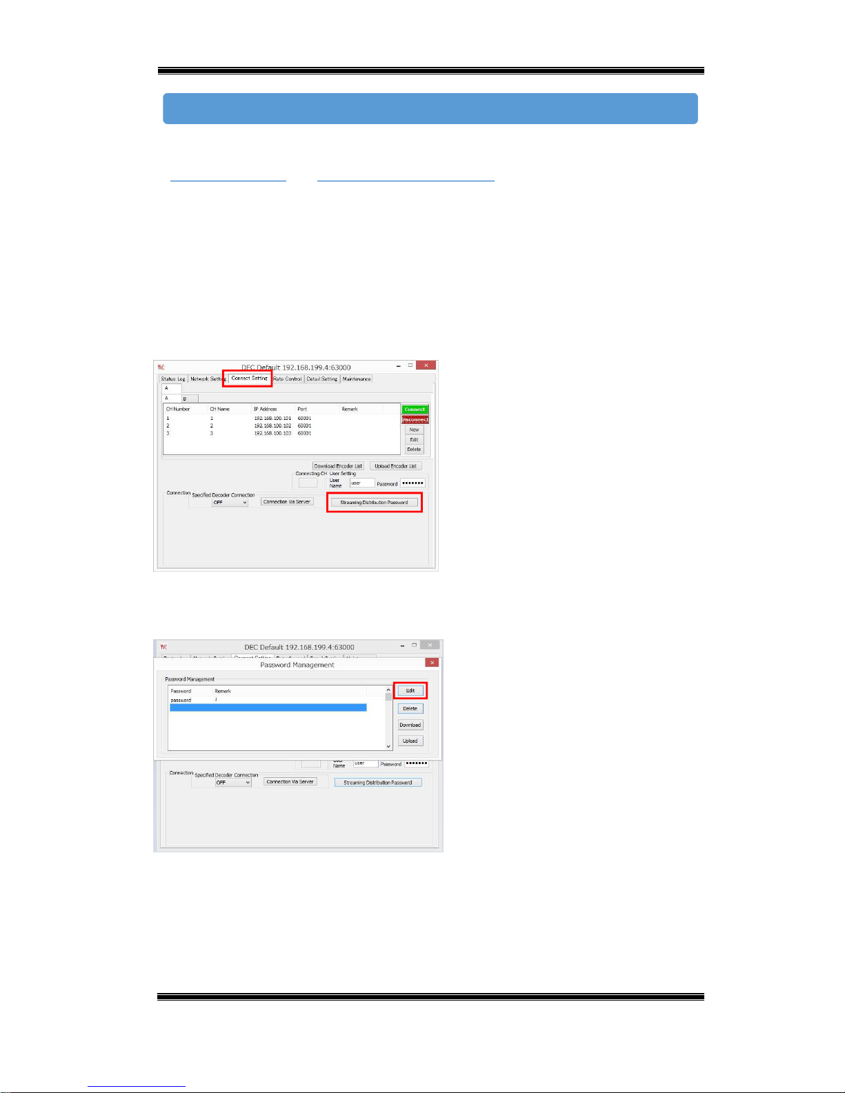
(1) Decoder (parent) Setup
Connect the setup PC to the decoder (parent) remote port and configure the settings
below.
Figure 6-1 Decoder (parent) – Streaming
Distribution Password
■ Start up DECODER.
■ On the Connect Setting tab, click
[Streaming Distribution Password].
Figure 6-2 Decoder (parent) – Password
Management
■ Click [Edit].
Connection Procedure
Page 41
Compact IP Codec User's Manual
40
Techno Mathematical Co., Ltd.
2140P
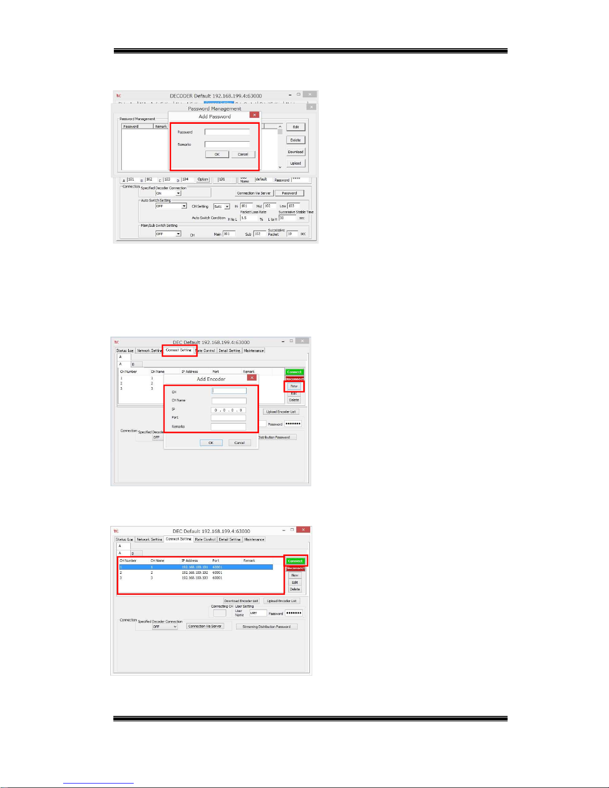
Figure 6-3 Decoder (parent) – Add Password
■ Enter the password of the decoder
(child) and then click [OK].
*Remarks can be left blank.
(2) Decoder (child) Setup
Connect the setup PC to the decoder (child) remote port and configure the settings
below.
Figure 6-4 Decoder (child) – Add Password
■ Start up DECODER.
■ On the Connect Setting tab, click
[New].
■ Enter the decoder (parent) information
and then click [OK].
*Remarks can be left blank.
Figure 6-5 Decoder (child) – Connect
■ Select the decoder (parent) you want to
connect and then click [Connect].
If the parent decoder and child decoder
passwords match, the stream will be
distributed from the parent to the child
decoders.
Page 42

Compact IP Codec User's Manual
41
Techno Mathematical Co., Ltd.
2140P
Bidirectional Audio Call
In addition to the standard video and audio transmission from an encoder to a
decoder, this function receives and transmits audio between the encoder and decoder.
Bidirectional audio calls between the encoder and decoder are enabled by connecting
headsets or other devices to the rear panel USB port.
r
Connection Diagram
USB cable
USB cable
Headset
Headset
LAN cable
HDMI cable
Encoder
Decoder
Internet
Setup PC
Camera
Camera cable
Video + Audio
*A USB port is located under the
rear panel cover.
Audio
Monitor
Page 43
Compact IP Codec User's Manual
42
Techno Mathematical Co., Ltd.
2140P
Connect a headset to the device USB port (under the rear panel cover).
Configure the settings below while the encoder and decoder are connected to
each other.
(1) Encoder Settings
Connect the setup PC to the encoder remote port and configure the settings below.
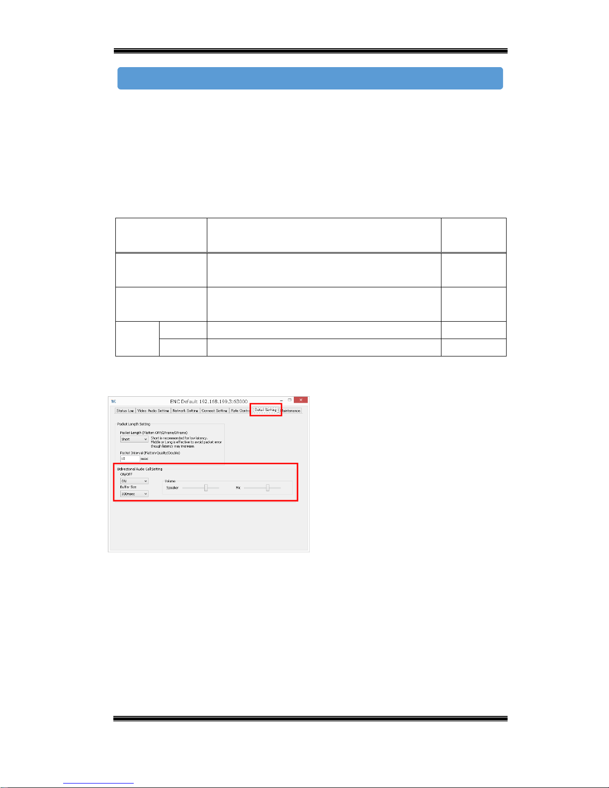
Table 6-1 Encoder – Bidirectional Audio Call Settings
Setting Description Initial
Default
ON/OFF Turns bidirectional audio communication
ON/OFF.
ON
Buffer Size Sets the bidirectional audio buffer size.
(0/20/40/60/100/140/160/200/300/400/500msec)
100msec
Volume Speaker Set the volume of Speaker (0-9) 5
Mic Set the volume of Mic (0-9) 5
Encoder
Figure 6-6 Encoder – Bidirectional Audio
Call Setting
■ Start up ENCODER.
■ On the Detail Setting tab, select ON for
[Bidirectional Audio Call Setting].
■ Configure the Buffer Size setting.
■Adjust the Volume.
Connection Procedure
Page 44

Compact IP Codec User's Manual
43
Techno Mathematical Co., Ltd.
2140P
(2) Decoder Settings
Connect the setup PC to the decoder remote port and configure the settings below.
Table 6-2 Decoder – Bidirectional Audio Call Settings
Setting Description Initial
Default
Send Voice Turns bidirectional audio communication
ON/OFF.
ON
Buffer Size Sets the bidirectional audio buffer size.
(0/20/40/60/100/140/160/200/300/400/500msec)
100msec
HDMI L Sets the audio output of HDMI output L.
(None / HDMI/SDI L / USB)
HDMI/SDI
L
HDMI R Sets the audio output of HDMI output R.
(None / HDMI/SDI R / USB)
HDMI/SDI
R
USB L Sets the audio output of the connected USB audio
output equipment L. (None / HDMI/SDI L / USB)
USB
USB R Sets the audio output of the connected USB audio
output equipment R. (None / HDMI/SDI R / USB)
USB
Volume Speaker Set the volume of Speaker (0-9) 5
Mic Set the volume of Mic (0-9) 5
Decoder
Figure 6-7 Decoder – Bidirectional Audio Call
Setting
■ Start up DECODER.
■ On the Detail Setting tab, select ON
for [Send Voice].
■ Configure the Buffer Size setting.
■ Configure the settings in the [Audio
Output Select] group in accordance with
the mode of use.
■Adjust the Volume.
*If the USB cable of the headset you are using becomes disconnected, plug it
back in, and then turn the device off and back on again.
Page 45

Compact IP Codec User's Manual
44
Techno Mathematical Co., Ltd.
2140P
Auto Rate Control
This function automatically adjusts the transmission bit rate in accordance with the
network line. The bit rate is lowered when the bandwidth capacity is low, and raised
when it is high.
6.3.1. Encoder Rate Control Operation Settings
Figure 6-8 Encoder – Rate Control
■ Start up ENCODER.
■ On the Rate Control tab, configure
settings as shown in the table on the
next page of this manual.
Figure 6-9 Encoder – Rate
■ Select ON for [Rate].
Page 46

Compact IP Codec User's Manual
45
Techno Mathematical Co., Ltd.
2140P
Table 6-3 Encoder – Auto Rate Control Settings
Setting Description
Rate ON/OFF
(Rate control operation starts when encoder and decoder are
both ON.)
Incoming Rate
Measurement Time
Packet loss rate measurement time (1 to 99 seconds)
(The packet loss rate is calculated and controlled within the
interval of this time setting.)
Outgoing Rate Up Time Rate increase time (1 to 99 seconds)
(The transmission rate is raised when the packet loss rate
does not exceed the packet loss rate setting of the table
during this time setting.)
Outgoing Rate Initial
Value
Initial transmission rate
(This is the transmission rate when the rate control
operation is started up.)
Outgoing Rate Max Maximum transmission rate
(This is the maximum transmission rate during the rate
control operation.)
Loss Rate Margin Loss rate margin
(Small(x1.0), Medium(x1.3), Large(x1.6)
The packet loss rate is compared with the value obtained by
multiplying this value with the packet loss rate setting. As
the loss rate margin becomes higher, the more difficult it is
to reduce the transmission rate.
Flatten
Flattening mode. For details, refer to "7.4
Flatten Setting
."
Outgoing Rate Round Trip
Count to Stable State
Number of transmission rate round trips (1 to 99) until
transition to stable state.*3
Outgoing Rate Up Time of
Stable State
Rate increase time in stable state (1 to 9999 seconds)
Outgoing Rate
Continuously Down Count
to Cancel Stable State
Number of continuous rate reductions (1 to 99) until stable
state is canceled.
Use Loss Rate Type Used packet loss rate (Average, Max)
*3
When there is repeated raising and lowering of the transmission rate using rate control, it is
judged to be the optimal current transmission rate. This state is the stable state, and the rise
frequency of the transmission rate can be set to reduce.
Page 47

Compact IP Codec User's Manual
46
Techno Mathematical Co., Ltd.
2140P
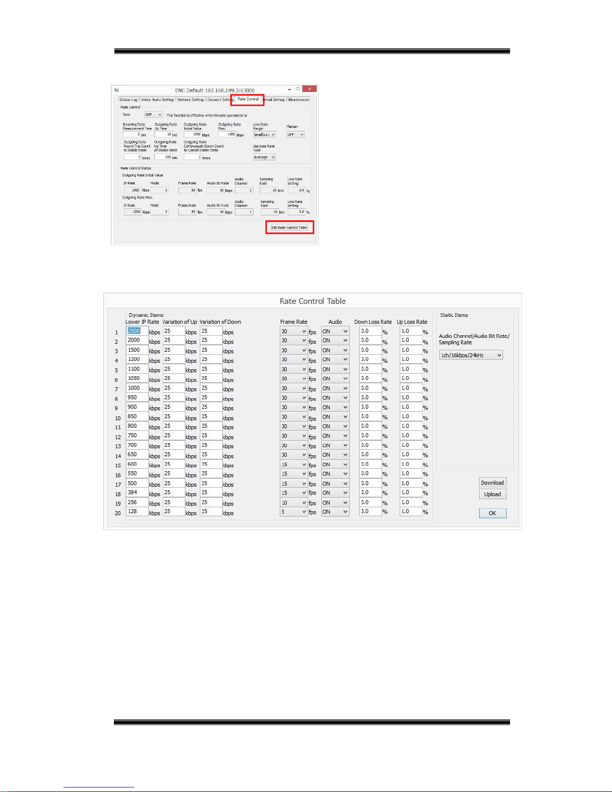
Rate Control Table Settings
This section explains configuration of settings for the rate migration packet loss rate,
transmission rate, and encode parameters.
Configure the settings below.
Table 6-4 Encoder – Rate Control Table Settings
Setting Description
Audio Channel / Audio Bit Rate
/ Sampling Rate
Number of audio channels, bit rate, sampling
frequency
(This item is in common with rate control table all
records.)
Lower Limit IP Rate Lower limit transmission rate (64 to 3000 kbps)
(When the transmission rate drops below this setting,
operation is performed according to the lower record
setting value.)
Variation of Up IP Rate Increase transmission rate (1 to 999 kbps)
Variation of Down IP Rate Decrease transmission rate (1 to 999 kbps)
Frame Rate Frame rate (5, 10, 15, 30)
Down Loss Rate Rate decrease packet loss rate (0 to 25.5%)
(The transmission rate is dropped when the receive
packet loss exceeds this setting value.)
Up Loss Rate Rate increase packet loss rate (0 to 25.5%)
(The transmission rate is raised when the receive
packet loss rate is less than this setting value.)
Audio Audio output setting (ON/OFF)
Page 48
Compact IP Codec User's Manual
47
Techno Mathematical Co., Ltd.
2140P
Figure 6-10 Encoder – Rate Control
■ Start up ENCODER.
■ On the Rate Control tab, click [Edit
Rate Control Table].
■ Configure settings on the setup dialog
box.
Figure 6-11 Encoder – Rate Control Table
Page 49

Compact IP Codec User's Manual
48
Techno Mathematical Co., Ltd.
2140P
6.4.1. Decoder Rate Control Operation Setting
Select ON for this setting to use the auto rate control function. The initial default
setting is OFF.
Figure 6-12 Decoder – Rate Control
■ Start up DECODER.
■ On the Rate Control tab, select ON for
[Rate Control].
Rate control operation starts when rate
control of the encoder is ON.
*Even if OFF is selected for this setting, rate control is operational if there are
multiple decoders connected to the encoder, and ON is selected for the encoder's and
another decoder's rate control setting. The packet loss rate does not reflect the rate
control of a decoder for which OFF is selected for the rate control setting.
Page 50
Compact IP Codec User's Manual
49
Techno Mathematical Co., Ltd.
2140P
7. Settings that Suit the Network Environment
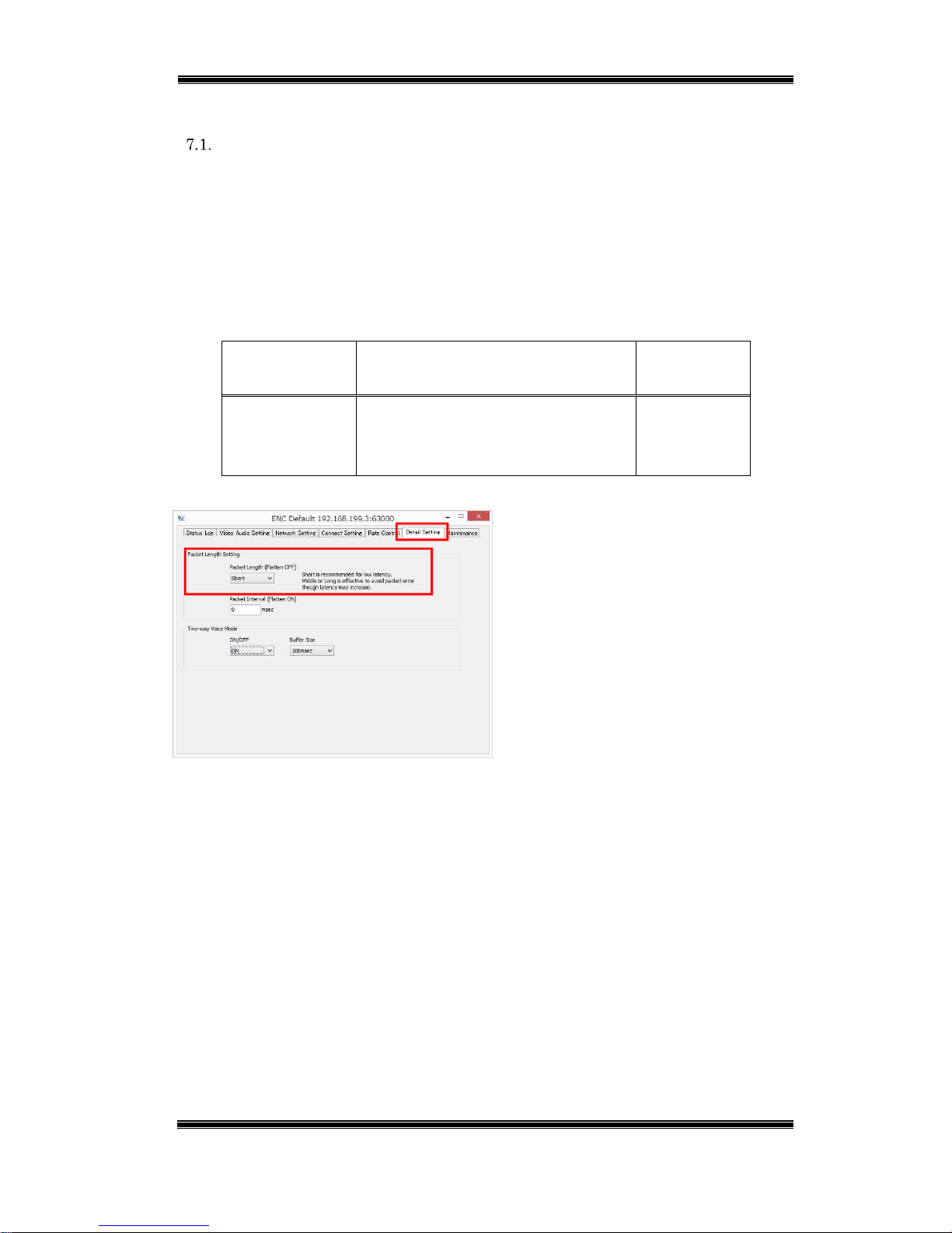
Packet Length Setting
This setting specifies a packet length to suit the network environment. A longer
packet length results in a longer packet transmission interval. Depending on the
network environment, the packet loss may be suppressed, or the packet may not be
passed if a packet length is long.
Configure the settings below.
Table 7-1 Decoder – Packet Length Settings
Setting Description Initial
Default
Packet Short: 500 bytes maximum
Middle: 1000 bytes maximum
Long: 1410 bytes maximum
Short
Figure 7-1 Decoder – Packet Length Setting
■ Start up ENCODER.
■ On the Detail Setting tab, configure
the setting in the [Packet Length
Setting] group.
Page 51
Compact IP Codec User's Manual
50
Techno Mathematical Co., Ltd.
2140P
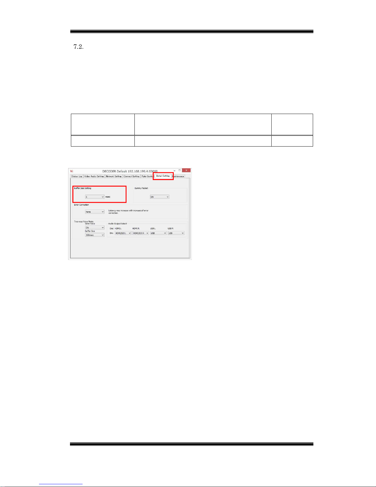
Buffer Size Setting
If the sequence of packets which the decoder received is changed, the packet
sequence is rearranged into proper sequence in the buffer and then decoded. This
setting is valid in an environment where packet sequence switching is performed.
Configure the settings below.
Table 7-2 Decoder – Buffer Size Setting
Setting Description Initial
Default
Buffer Size Setting 0/20/40/70/100/140/170/200/300/400/500msec 0msec
Figure 7-2 Decoder – Buffer Size Setting
■ Start up DECODER.
■ On the Detail Setting tab, configure
setting in the [Buffer Size Setting] group.
*
The larger the setting value, the greater the range over which packet sequence can
be rearranged, but a larger value also increases latency.
Page 52
Compact IP Codec User's Manual
51
Techno Mathematical Co., Ltd.
2140P
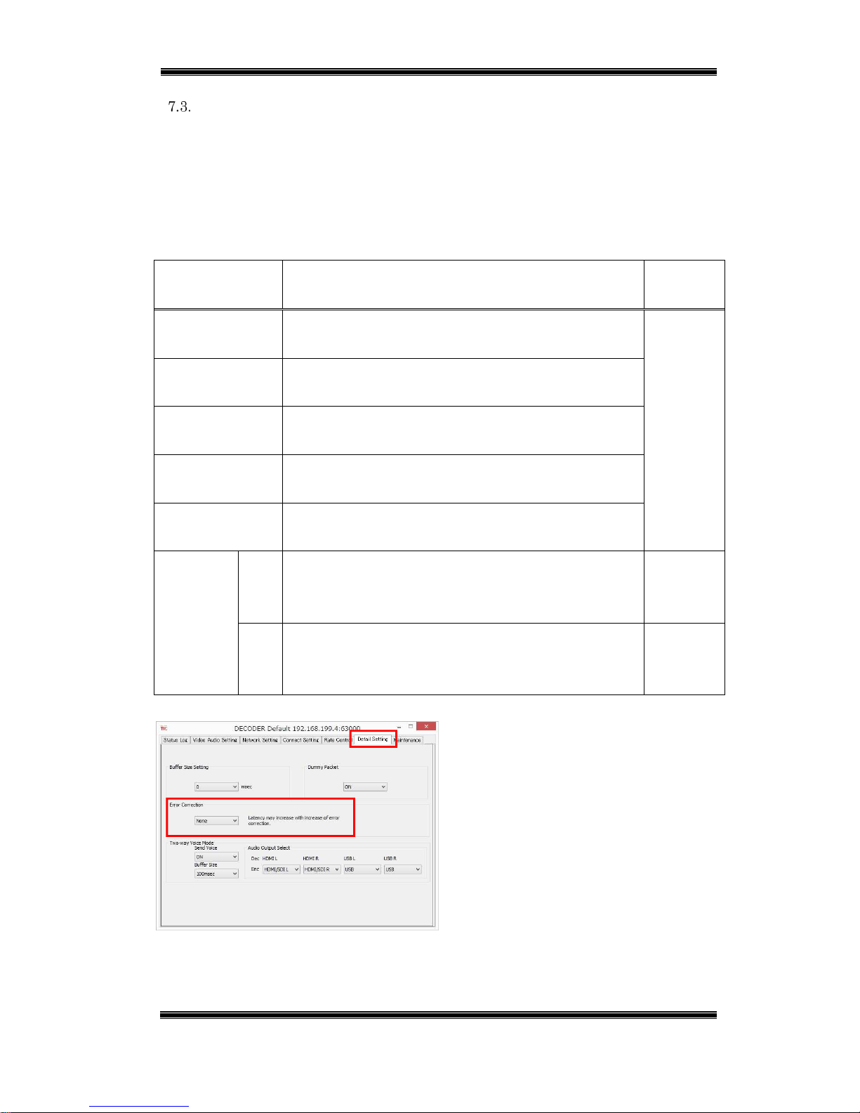
Error Correction Settings
Transmission of redundant packets for error correction is used for packet correction
when packet loss occurs. This setting is valid in an environment where packet loss
occurs.
Configure the settings below.
Table 7-3 Decoder – Error Correction Setting
Setting Description Initial
Default
None Redundant packets for error correction not
transmitted.
None
x1.5 Redundant packets for error correction transmitted in
a volume that is half of the transmission rate.
x2.0 Redundant packets for error correction transmitted in
a volume that is the same as the transmission rate.
Pro-MPEG
(Dim1)
Tolerant redundant packets for error correction
transmitted in a burst packet loss.
Pro-MPEG
(Dim2)
Tolerant redundant packets for error correction
transmitted in a burst random packet loss.
Pro-MPEG
matrix
size
cols The number of restored burst packet losses (1-32).
As this value becomes higher, tolerant for
burst packet
loss
is increased.
4
rows The rate of the redundant packet (1-32)
As this value is smaller, the rate of the redundant
packet becomes so a lot.
4
Figure 7-3 Decoder – Error Correction
■ Start up DECODER.
■ On the Detail Setting tab, configure the
setting in the [Error Correction] group.
Page 53

Compact IP Codec User's Manual
52
Techno Mathematical Co., Ltd.
2140P
*
The bit rate is increased by the amount of transmitted redundant packets for error
correction.
* When Pro-MPEG matrix size is bigger, delay is increased.
Page 54
Compact IP Codec User's Manual
53
Techno Mathematical Co., Ltd.
2140P
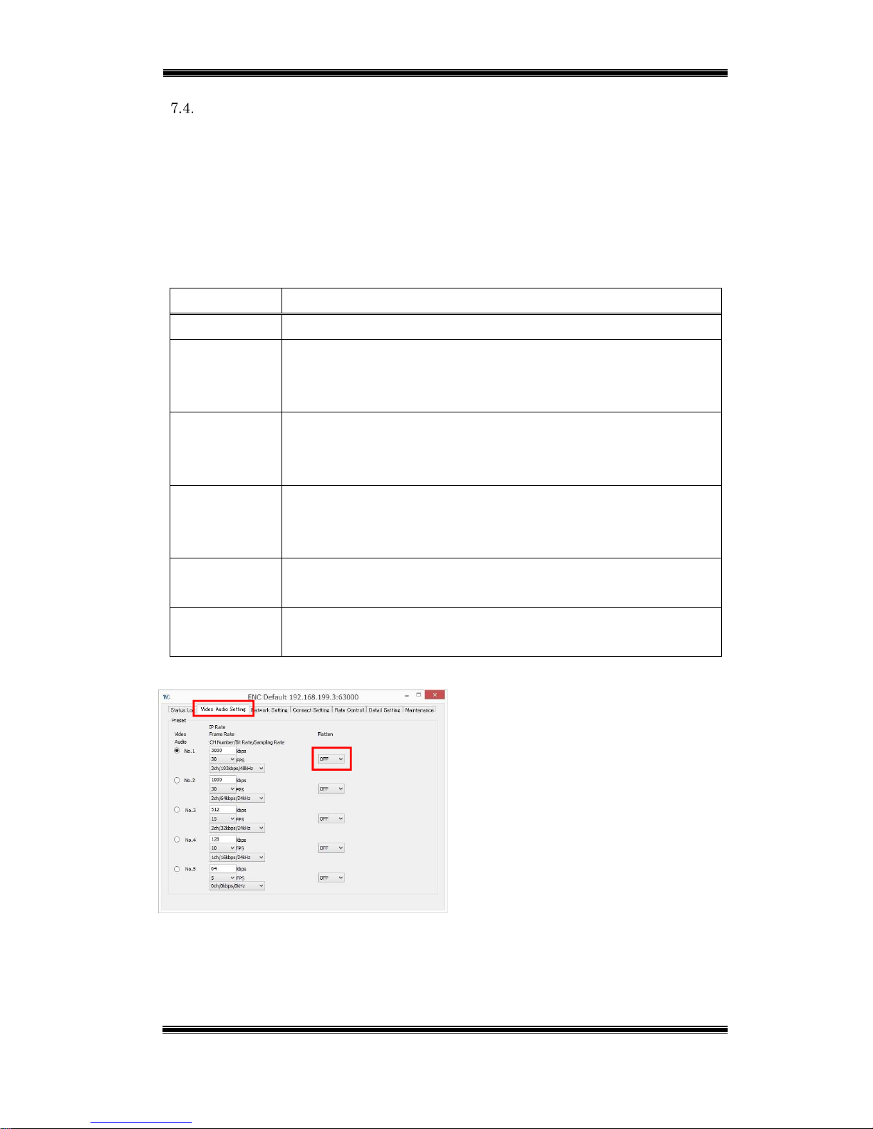
Flatten Setting
For the video stream, the input video can cause ripples in the output bit rate. The
flatten setting outputs the encoder output packets in a fixed interval, which flattens
the transmission rate. This setting is valid on a bandwidth guaranteed line and on a
low bandwidth line.
Configure the settings in the table below.
Table 7-4 Encoder – Flatten Setting
Setting Description
OFF Outputs packets without flattening.
LowDelay Low latency priority mode
Image quality is reduced, but latency increase is kept to about 10
to 30 msec.
Quality Image quality priority mode
Image quality is equivalent to that when OFF is selected for
flattening. Latency is increased by about one second.
Double Approximately doubles the value that sets the transmission rate
peak, and transmits with lower latency than Quality without a
drop in quality. Latency is increased by about 500 msec.
2Frame Flattens the stream in two-frame units.
Latency is increased by two frames.
3Frame Flattens the stream in three-frame units.
Latency is increased by three frames.
Figure 7-4 Encoder – Flatten
■ Start up ENCODER.
■ On the Video Audio Setting tab,
configure the setting in the Flatten
setting.
Page 55
Compact IP Codec User's Manual
54
Techno Mathematical Co., Ltd.
2140P
8. Maintenance
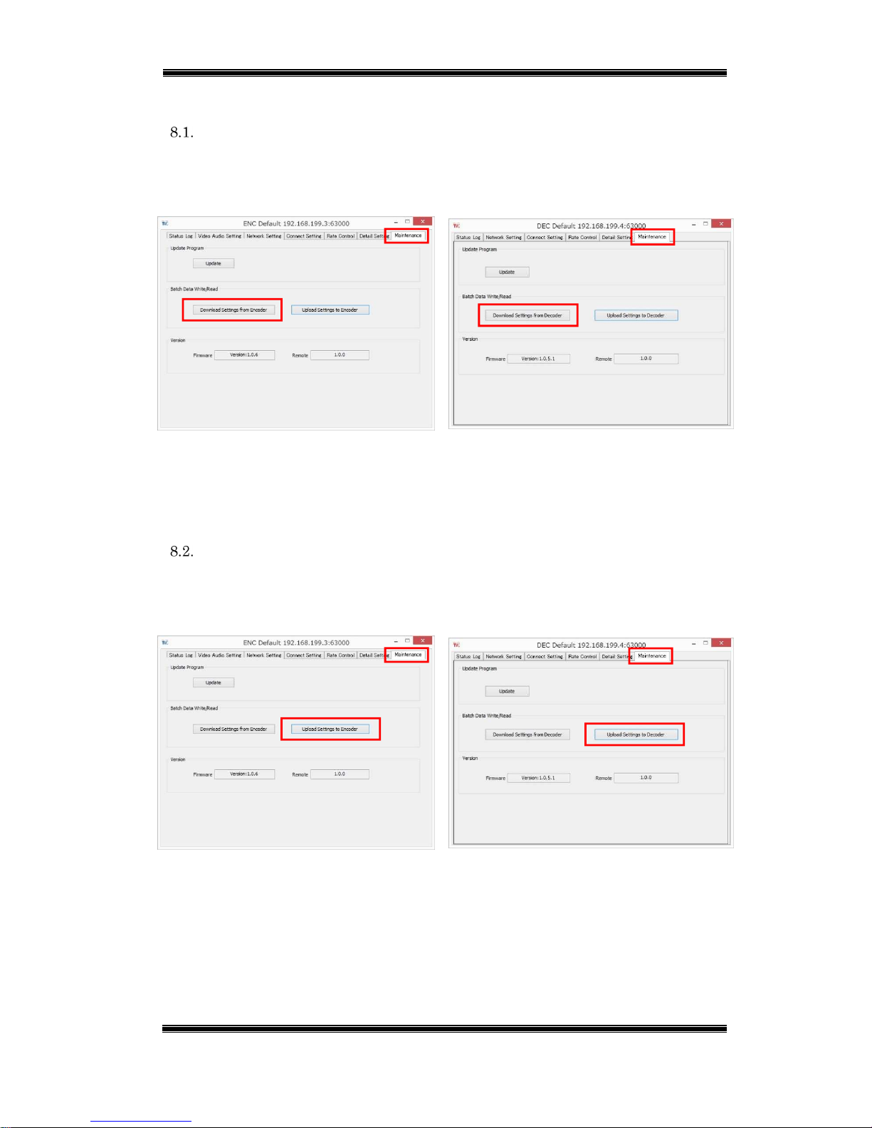
Setting File Download
On the Maintenance tab, click [Download Settings from Encoder] for the encoder,
and [Download Settings from Decoder] for the decoder.
Encoder
Decoder
Figure 8-1 Download Setting
Specify the file storage destination and then click [Save].
The setting file contains all setting values of these devices in CSV format.
Setting File Upload
On the Maintenance tab, click [Upload Settings to Encoder] for the encoder, and
[Upload Settings to Decoder] for the decoder.
Encoder
Decoder
Figure 8-2 Upload Setting
Select a file and then click [Open].
Page 56
Compact IP Codec User's Manual
55
Techno Mathematical Co., Ltd.
2140P
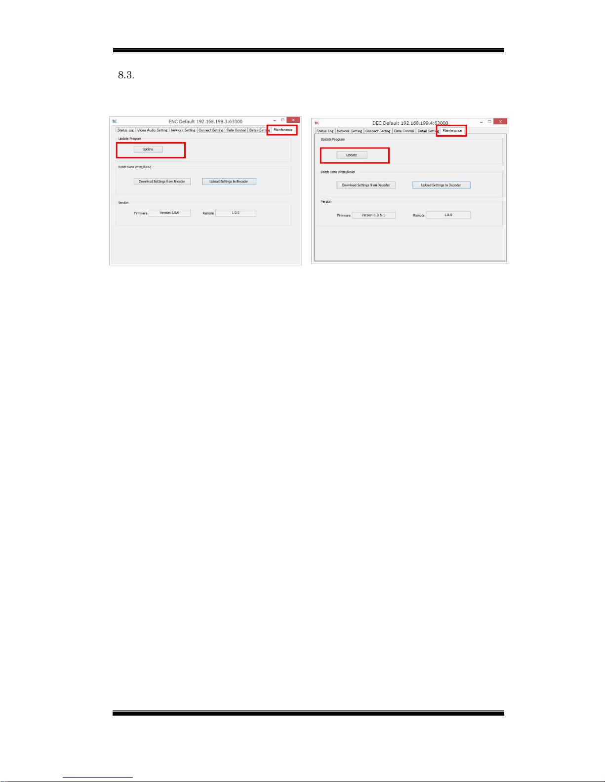
Firmware Update
On the Maintenance tab, click [Update].
Encoder
Decoder
Figure 8-3 Update
Select a file and then click [Open].
Page 57
Compact IP Codec User's Manual
56
Techno Mathematical Co., Ltd.
2140P
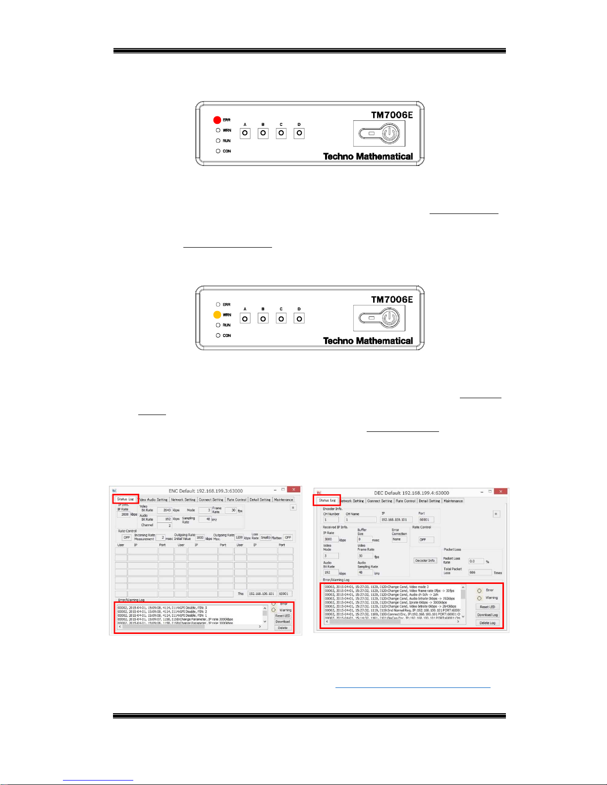
9. Error and Warning Indicators
The ERR LED (red) lights when an error occurs.
Figure 9-1 ERR LED
The behavior of the ERR LED depends on the error type.
(1) The ERR LED goes out when the cause of the error is eliminated. : Recorded in log.
(2) The ERR LED does not go out until power is turned off or the reset button is
pressed. : Not recorded in log.
The WRN LED (orange) lights when a warning occurs.
Figure 9-2 WRN LED
The behavior of the WRN LED depends on the warning type.
(1) The WRN LED goes out when the cause of the warning is eliminated. : Recorded
in log.
(2) The WRN LED goes out after about five seconds. : Recorded in log.
Recorded log entries can be viewed on the Status Log tab of the application software.
Encoder
Decoder
Figure 9-3 Status Log
*Though information is also displayed, it is not recorded in the log.
For details about errors and warnings, refer to "Appendix 1. Errors and Warnings."
Page 58

Compact IP Codec User's Manual
57
Techno Mathematical Co., Ltd.
2140P
Appendix 1. Errors and Warnings
Errors
Number
Log Output Description Required Action LED Transition
E-001 E001:Parameter Error Though incorrect
parameter settings are
normally not possible to
set on the setting screen,
an incorrect parameter
was discovered when
actual transmission
started.
The problem parameter
will be shown on the
display, so review the
settings of the applicable
parameter and its related
parameters.
The LED goes out when
the correct setting is
configured and the
output is started.
E-002 E002:FileWriteErr Writing to built-in flash
memory failed.
If writing is not possible
after three retries,
contact TMC support.
At any point when
writing is not
successful for the first
three times, the LED
transitions as follows:
Lit 5 seconds -> Unlit.
E-003 E003:GBT Not Detect Image port cannot be
detected.
Contact TMC Support. LED lit only (does not
go out).
E-004 E004:Panel Con. ERR Panel communication
error (remote screen and
log only)
Contact TMC Support. LED lit only (does not
go out).
E-005 E005:AES Not Detect AES devices not
connected to and AES
compatible device.
Connect the AES device
correctly.
Goes out upon AES
device connection.
E-100 E100:Connect Err Could not connect to
encoder. (During user
authentication)
Check the password.
Check the connection
destination Tx IP
address, channel number,
etc.
Confirm that there are
fewer than 20 connection
destination Tx connected.
(On encoder)
Goes out upon
connection.
E-101 E101:Tx Discon Disconnection of line
with the encoder.
Connect a different
encoder.
Change to the line
disconnection support
mode, and then connect
the line again.
In the case of a line
disconnection support
mode, connecting to the
set encoder will cause
error LED to go out and
the warning LED to
light. Warning LED
goes out upon
connection.
E-103 E103:Miss Encrypt Key Could not obtain
encryption key.
LED lit for five seconds,
then goes out.
Page 59

Compact IP Codec User's Manual
58
Techno Mathematical Co., Ltd.
2140P
E-104 E104:LAN corrupted LAN cable not be
connected or
disconnected.
Connect the LAN cable. Goes out when LAN
cable is connected.
E-110 E110:Wrong PWD Password registered on
the encoder and
password set by the
decoder are different.
From the Setup menu,
set the passwords on the
encoder and decoder to be
the same.
LED lights for five
seconds then goes out.
Note that this is
treated as a warning by
the encoder, and as an
error by the decoder.
E-300 E300:Video rate Low Video rate cannot be set
correctly because the
transmission rate
setting is too low.
(Example: For a
transmission rate of 64
kbps, and audio rate of
32 kbps, and packet
header loss of 16 kbps,
video becomes 16 kbps.)
*Though this is a type of
parameter error,
ParameterErr is not
output when this error is
output.
Increase the overall
transmission rate.
Make audio Channel 0
(no output).
Make audio 16 kbps.
Make PacketSize bigger
(which increases latency).
LED lit for five seconds,
then goes out.
E-800 E800: Appli Down Application software is
down.
Contact TMC Support. Goes out when app is
restarted.
E-801 E801:WDT Det. Watchdog timer
operation.
Contact TMC Support. Goes out when device is
restarted.
Page 60

Compact IP Codec User's Manual
59
Techno Mathematical Co., Ltd.
2140P
Warnings
Number
Log Output Description Required Action LED Transition
W-002 W002:Log File Over Log file exceeds 100
MB.
Nothing in particular LED lit, goes out by
log clear.
W-010 W010:Rx Ilg. Dis-con. The decoder
disconnected from the
line without following
the proper
disconnection process.
(Disconnection: Packet
report packets could
not be received within
an interval of at least
10 packets while there
was no decoder
disconnect request.
Nothing in particular Goes out at the time
when packet
transmission from the
encoder stops.
W-101 W101:Wrong PWD Mismatch with the
registered user
password.
All information is
registered in log output,
so check log output.
LED lit for five
seconds, then goes out.
W-102 W102:MAX RX OVR The 20-unit maximum
allowable number of
decoder connections
was exceeded.
Reduce the number of
decoder connections
LED lit for five
seconds, then goes out.
W-103 W103:RTC Cnt. Unmatch The rate control
ON/OFF settings of
the encoder and
decoder are different
(when UniCast and
encoder are ON).
Configure correction
connection settings.
(User operation standby)
LED lit for five
seconds, then goes out.
W-112 W112:Not Found Tx During normal
connection, the
connection destination
does not exist (channel
number, channel
name, IP address, and
other information).
Re-connect to a proper
connection destination.
However, note that
connection is abandoned
and requesting is
stopped if there is no
connection after three
tries.
LED lit for five
seconds, then goes out.
W-200 W200:Preset No Apply During rate control,
preset settings and
parameter changes
have no effect.
However, presets are
used for transmission
after rate control is
ended.
Nothing in particular LED lit for five
seconds, then goes out.
Page 61

Compact IP Codec User's Manual
60
Techno Mathematical Co., Ltd.
2140P
W-201 W-201: Preset changed Preset setting is
changed from
application software.
Press preset switches. LED lit, Preset LED is
flashing, goes out the
time when preset
switches is pressed
Page 62

Compact IP Codec User's Manual
61
Techno Mathematical Co., Ltd.
2140P
Appendix 2. Product Specifications
Encoder (TM7006E, TM7007E)
General
Power Requirements 12 VDC
Power Consumption Less than 20 W
Allowable Operating
Temperature
0°C to +50°C
Allowable Humidity 30% to 80%, Non-condensation
Location Indoors
External Dimensions 180mm(W) x 50mm(H) x 150mm(D)
*Excluding AC adapter and protrusions.
Weight Less than 1.5 kg
Network
Data
transmission
Format Ether Net(IEEE-802.3)
Transmission Rate 64kbps to 3Mbps
Transmission and
Transfer Protocols
UDP/IP
Maximum Number
of Decoders
Connected
20 units
Remote
connection
Format Ether Net(IEEE-802.3)
Transmit/Receive
Protocol
TCP/IP
Video
Input Format HDMI (TM7006E) or HD-SDI
(TM7007E)
1920 x 1080 60i/59.94i/30p/29.97p
1280 x 720 60p/30p
720 x 480 60i/59.94i/30p/29.97p
Automatically select
Encoding System TMC DMNA-V2M
Encoding Bit Rate 64kbps to 3Mbps
Encoding Frame Rate 5fps/10fps/15fps/30fps (1080, 480)
10fps/20fps/30fps/60fps (720)
Audio
Input Format
HDMI (TM7006E) or HD-SDI (TM7007E)
Embedded 2ch.
Encoding System OPUS
Encoding Sampling Rate 24kHz/48kHz
Number of Encoding Channels Selectable: None, 1ch., 2ch.
Page 63

Compact IP Codec User's Manual
62
Techno Mathematical Co., Ltd.
2140P
Encoding Bit Rate 32kbps/64kbps/128kbps/192kbps
Other
Bidirectional audio communication function
Auto rate control function
Page 64

Compact IP Codec User's Manual
63
Techno Mathematical Co., Ltd.
2140P
Decoder (TM7006D)
General
Power Requirements 12 VDC
Power Consumption Less than 20 W
Allowable Operating
Temperature
0°C to +50°C
Allowable Humidity 30% to 80%, Non-condensation
Location Indoors
External Dimensions 180mm(W) x 50mm(H) x 150mm(D)
*Excluding AC adapter and
protrusions.
Weight Less than 1.5 kg
Network
Data
transmission
Format Ether Net(IEEE-802.3)
Transmission Rate 64kbps to 3Mbps
Transmission and
Transfer Protocols
UDP/IP
Remote
connection
Format Ether Net(IEEE-802.3)
Transmit/Receive
Protocol
TCP/IP
Video
Output Format HDMI Automatically select
(1920 x 1080 Maximum)
Decoding System TMC DMNA-V2M
Decoding Bit Rate 64kbps to 3Mbps
Decoding Frame Rate 5fps/10fps/15fps/30fps (1080, 480)
10fps/20fps/30fps/60fps (720)
Audio
Output Format
HDMI(Embedded Audio)
Embedded 2ch.
Decoding System OPUS
Decoding Sampling Rate 24kHz/48kHz
Number of Decoding Channels Selectable: None, 1ch., 2ch.
Decoding Bit Rate 32kbps/64kbps/128kbps/192kbps
Other
Repeater function
Bidirectional audio communication function
Auto rate control function
Page 65

Compact IP Codec User's Manual
64
Techno Mathematical Co., Ltd.
2140P
Copyright of OPUS
Copyright (c) 2010/2011, Xiph. Org Foundation (USA), 2008/2010/2011, Broadcom
Corporation (USA), 2012, Microsoft Corporation (USA)
All rights reserved.
Redistribution and use in source and binary forms, with or without modification, are
permitted provided that the following conditions are met:
1. Redistributions of source code must retain the above copyright notice, this list of
conditions and the following disclaimer.
2. Redistributions in binary form must reproduce the above copyright notice, this
list of conditions and the following disclaimer in the documentation and/or other
materials provided with the distribution.
3. Neither the name of the copyright holder nor the names of its contributors may
be used to endorse or promote products derived from this software without
specific prior written permission.
THIS SOFTWARE IS PROVIDED BY THE COPYRIGHT HOLDERS AND
CONTRIBUTORS "AS IS" AND ANY EXPRESS OR IMPLIED WARRANTIES,
INCLUDING, BUT NOT LIMITED TO, THE IMPLIED WARRANTIES OF
MERCHANTABILITY AND FITNESS FOR A PARTICULAR PURPOSE ARE
DISCLAIMED. IN NO EVENT SHALL THE COPYRIGHT HOLDER OR
CONTRIBUTORS BE LIABLE FOR ANY DIRECT, INDIRECT, INCIDENTAL,
SPECIAL, EXEMPLARY, OR CONSEQUENTIAL DAMAGES (INCLUDING, BUT
NOT LIMITED TO, PROCUREMENT OF SUBSTITUTE GOODS OR SERVICES;
LOSS OF USE, DATA, OR PROFITS; OR BUSINESS INTERRUPTION) HOWEVER
CAUSED AND ON ANY THEORY OF LIABILITY, WHETHER IN CONTRACT,
STRICT LIABILITY, OR TORT (INCLUDING NEGLIGENCE OR OTHERWISE)
ARISING IN ANY WAY OUT OF THE USE OF THIS SOFTWARE, EVEN IF
ADVISED OF THE POSSIBILITY OF SUCH DAMAGE.
Page 66

 Loading...