


User’s Guide
Please read before using telephone.

Getting Started
Congratulations! You’ve purchased a TMC EPIC System Intercom Speakerphone that meets the highest standards for quality and convenience in the Small Office/Home Office environment. To get the most from your system, please take time to read this guide thoroughly.
IMPORTANT SAFETY INSTRUCTIONS
When using your telephone equipment, basic safety precautions should always be followed to reduce the risk of fire, electric shock and injury to persons, including the following:
1.Do not use this product near water, for example, near a bath tub, wash bowl, kitchen sink, or laundry tub, in a wet basement, or near a swimming pool.
2.Avoid using a telephone (other than a cordless type) during an electrical storm. There may be a remote risk of electric shock from lightning.
3.Do not use the telephone to report a gas leak in the vicinity of the leak.
4.Use only the power cord and batteries indicated in this manual. Do not dispose of batteries in a fire. They may explode. Check with local codes for possible special disposal instructions.
SAVE THESE INSTRUCTIONS
i
Getting Started
Before you begin . . .
The TMC EPIC System Intercom Speakerphone is designed for easy installation in your home or office. However, it is important that you follow these few simple guidelines:
-Take a few minutes to read this manual so that you thoroughly understand the instructions to be followed for proper installation of your EPIC System phones.
-This User’s Guide provides easy to understand directions for operation of your system. Please retain these instructions for future reference when adding stations or making changes to your system.
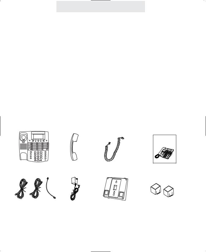
Packing List
Remove the unit from the package and check this list to be certain all parts are included:
User’s Guide
Telephone Base Unit |
Handset |
Coiled Handset Cord |
This User’s Guide |
Telephone Line Cords |
AC Adapter |
Wall Mount |
Two Desk Pedestal |
(2 long and 1 short) |
|
Bracket/Desk Pedestal |
Feet |
To order any packing list items, call toll-free 1-800-TMC-1638.
ii
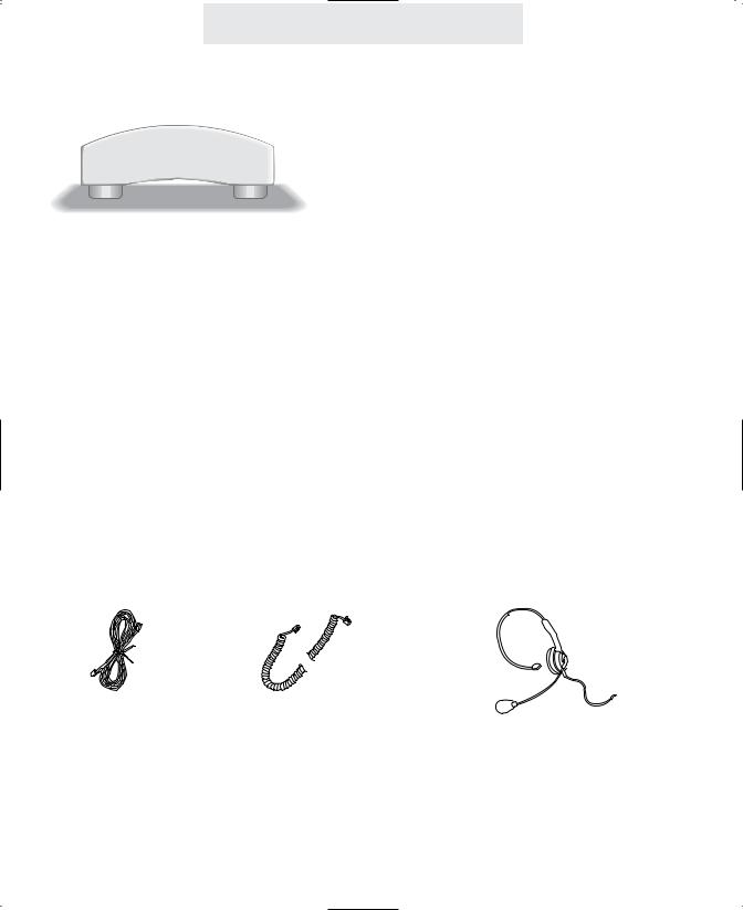
Optional Accessories
External Feature Module (Model number 800-EFM)
The External Feature Module is an exciting addition to the EPIC System. It offers ONE of the following features, which you decide by setting switches on the module itself. If you ever need more than one feature, you can add additional Feature Modules to your system.
Each External Feature Module offers ONE of the following features:
Music On Hold Adapter
Enables you to hook-up your radio or a continuous loop recorded message to the system to provide professional music or a recorded message to callers on hold.
External Paging Adapter
Allows the connection of an external amplifier and speaker to the system, for paging from any EPIC telephone. Perfect for warehouses, outdoors, or for making announcements throughout an entire office.
Door Intercom/Door Opener Adapter
Enables you to connect a door intercom speaker to the system. Also enables you to connect a magnetic door strike, which can be opened from any station. Perfect for warehouses, front doors or unattended entrances.
Other Optional Accessories:
25-foot line cord |
25-foot handset cord |
headset |
To order an accessory or get the name of the TMC Dealer nearest you, call toll-free 1-800-TMC-1638.
iii

Table of Contents
Getting Started . . . . . . . . . . . . . . . . . . . . . . . . . . . . . . . . . . . . . . . . . . . .i
Location of Controls . . . . . . . . . . . . . . . . . . . . . . . . . . . . . . . . . . . . . . .vii
Installing Your System . . . . . . . . . . . . . . . . . . . . . . . . . . . . . . . . . . . . . .1-9
Step 1: Identify Your Existing Wiring System . . . . . . . . . . . . . . . . .1
Step 2: Plan Your Installation . . . . . . . . . . . . . . . . . . . . . . . . . . . . .2
Step 3: Install Desk/Table Top Phones . . . . . . . . . . . . . . . . . . . . . .4
Step 4: Install Wall Mounted Phones . . . . . . . . . . . . . . . . . . . . . . .6
Assigning Station Numbers . . . . . . . . . . . . . . . . . . . . . . . . . . . . . .8 Verifying Proper Installation . . . . . . . . . . . . . . . . . . . . . . . . . . . . . .9
Setting Up Your System . . . . . . . . . . . . . . . . . . . . . . . . . . . . . . . . . . . . .10-19
Setting Up Your System at a Glance . . . . . . . . . . . . . . . . . . . . . . .10 Setting Automatic Line Selection . . . . . . . . . . . . . . . . . . . . . . . . . .12 Setting Distinctive Ringing . . . . . . . . . . . . . . . . . . . . . . . . . . . . . . .13 Setting Up Toll Restriction . . . . . . . . . . . . . . . . . . . . . . . . . . . . . . .14
Setting System Call Privacy On/Off . . . . . . . . . . . . . . . . . . . . . . . .18
Setting Up Private, Auxiliary and Unconnected Lines . . . . . . . . . . .19
Operating Your System . . . . . . . . . . . . . . . . . . . . . . . . . . . . . . . . . . . . .20-43
Using the Desk Pedestal/Wall Mount Bracket . . . . . . . . . . . . . . . . .20
Indicator Light Description . . . . . . . . . . . . . . . . . . . . . . . . . . . . . . .21
Setting Ringers On/Delayed/Off . . . . . . . . . . . . . . . . . . . . . . . . . . .22
Adjusting Volume Levels . . . . . . . . . . . . . . . . . . . . . . . . . . . . . . . .23
Making a Tone/Pulse Selection . . . . . . . . . . . . . . . . . . . . . . . . . . .24
Making and Answering a Call . . . . . . . . . . . . . . . . . . . . . . . . . . . . .25
Using Redial . . . . . . . . . . . . . . . . . . . . . . . . . . . . . . . . . . . . . . . . .26
Using Hold . . . . . . . . . . . . . . . . . . . . . . . . . . . . . . . . . . . . . . . . . .27
Using Another Line During a Conversation . . . . . . . . . . . . . . . . . . .28
iv

Table of Contents
Operating Your System (Continued) |
|
Conferencing Calls . . . . . . . . . . . . . . . . . . . . . . . . . . . . . . . . . . . |
.29 |
Transferring Calls . . . . . . . . . . . . . . . . . . . . . . . . . . . . . . . . . . . . |
.30 |
Using Caller ID . . . . . . . . . . . . . . . . . . . . . . . . . . . . . . . . . . . . . . |
.32 |
Using Telephone Company Voice Mail . . . . . . . . . . . . . . . . . . . . . . |
34 |
Using Flash . . . . . . . . . . . . . . . . . . . . . . . . . . . . . . . . . . . . . . . . . . |
35 |
Using Mute . . . . . . . . . . . . . . . . . . . . . . . . . . . . . . . . . . . . . . . . . . |
36 |
Using Do Not Disturb . . . . . . . . . . . . . . . . . . . . . . . . . . . . . . . . . . . |
37 |
Using Line Reserve . . . . . . . . . . . . . . . . . . . . . . . . . . . . . . . . . . . . |
38 |
Releasing Call Privacy . . . . . . . . . . . . . . . . . . . . . . . . . . . . . . . . . . |
39 |
Using Toll Restriction . . . . . . . . . . . . . . . . . . . . . . . . . . . . . . . . . . . |
40 |
Using the Call Timer . . . . . . . . . . . . . . . . . . . . . . . . . . . . . . . . . . . |
41 |
Using a Headset with Your Epic Telephone . . . . . . . . . . . . . . . . . . |
42 |
Adjusting Your Telephone’s Time and Date . . . . . . . . . . . . . . . . . . |
43 |
Memory Dialing . . . . . . . . . . . . . . . . . . . . . . . . . . . . . . . . . . . . . . . . . . .44-49
Memory Features . . . . . . . . . . . . . . . . . . . . . . . . . . . . . . . . . . . . .44
Using Memory Dial . . . . . . . . . . . . . . . . . . . . . . . . . . . . . . . . . . . .45
Using Personal Directory Dial . . . . . . . . . . . . . . . . . . . . . . . . . . . .46
Using Shared Directory Dial . . . . . . . . . . . . . . . . . . . . . . . . . . . . . .47
Special Memory Features . . . . . . . . . . . . . . . . . . . . . . . . . . . . . . .48
Intercom Operation . . . . . . . . . . . . . . . . . . . . . . . . . . . . . . . . . . . . . . . .50-57
Making Intercom Calls . . . . . . . . . . . . . . . . . . . . . . . . . . . . . . . . . .50
Answering Intercom Calls . . . . . . . . . . . . . . . . . . . . . . . . . . . . . . .51
Making Pages . . . . . . . . . . . . . . . . . . . . . . . . . . . . . . . . . . . . . . . .52
Answering Pages . . . . . . . . . . . . . . . . . . . . . . . . . . . . . . . . . . . . . .53 Selecting Intercom Ring, Intercom Voice, or Handsfree . . . . . . . . .54 Using Off Hook Voice Announce . . . . . . . . . . . . . . . . . . . . . . . . . .55 Monitoring a Room Using the Intercom . . . . . . . . . . . . . . . . . . . . .56 Naming Stations . . . . . . . . . . . . . . . . . . . . . . . . . . . . . . . . . . . . . .57
v

Table of Contents
Expanding the Epic System . . . . . . . . . . . . . . . . . . . . . . . . . . . . . . . . .58-59
Standard Configuration . . . . . . . . . . . . . . . . . . . . . . . . . . . . . . . . .58
Private Lines . . . . . . . . . . . . . . . . . . . . . . . . . . . . . . . . . . . . . . . .58
Auxiliary Lines . . . . . . . . . . . . . . . . . . . . . . . . . . . . . . . . . . . . . . .59
Centrex Operation . . . . . . . . . . . . . . . . . . . . . . . . . . . . . . . . . . . . . . . . .60-63
Using Centrex with your EPIC Telephone . . . . . . . . . . . . . . . . . . . .60
Storing the Centrex Prefix . . . . . . . . . . . . . . . . . . . . . . . . . . . . . . .61
Setting up a Telephone as a Centrex Console . . . . . . . . . . . . . . . .62
Setting a Telephone to Ring a Centrex Console . . . . . . . . . . . . . . .63
Additional Information . . . . . . . . . . . . . . . . . . . . . . . . . . . . . . . . . . . . . .64-78
Using Other Telephones with your EPIC Telephone . . . . . . . . . . . .64
Using the Data/Fax Jack . . . . . . . . . . . . . . . . . . . . . . . . . . . . . . . .65
Using Optional External Feature Module . . . . . . . . . . . . . . . . . . . .66
Replacing Your Battery . . . . . . . . . . . . . . . . . . . . . . . . . . . . . . . . .68
Adjusting Held Call Reminder . . . . . . . . . . . . . . . . . . . . . . . . . . . .69
Adjusting Auto Hold Drop Time . . . . . . . . . . . . . . . . . . . . . . . . . . .70
Adjusting Flash Length . . . . . . . . . . . . . . . . . . . . . . . . . . . . . . . . .71
Erasing All Feature Settings . . . . . . . . . . . . . . . . . . . . . . . . . . . . . .72
Setting the Loop Voltage Detector . . . . . . . . . . . . . . . . . . . . . . . . .73
Troubleshooting Guide . . . . . . . . . . . . . . . . . . . . . . . . . . . . . . . . . .74
FCC Information . . . . . . . . . . . . . . . . . . . . . . . . . . . . . . . . . . . . . .76
Warranty Information . . . . . . . . . . . . . . . . . . . . . . . . . . . . . . . . . . .78
Index . . . . . . . . . . . . . . . . . . . . . . . . . . . . . . . . . . . . . . . . . . . . . . . . . . . .80-81
vi
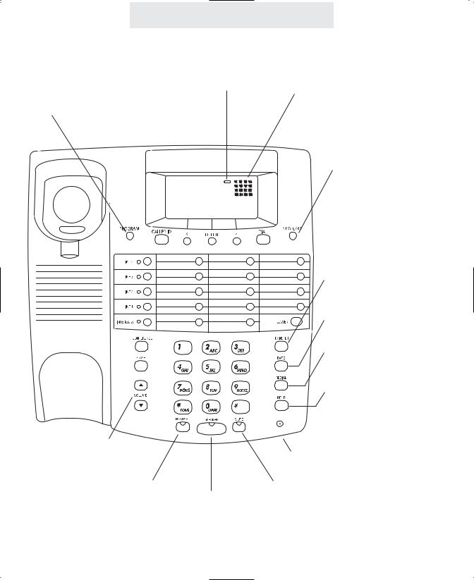
Location of Controls
LOW BATTERY
Indicator (p. 68)
PROGRAM Button (pp. 10-19, 44-57)
VOLUME Control
Buttons (p. 23)
HEADSET Button and
Indicator (p. 42) SPEAKER Button and
Indicator (pp. 25, 50-56)
Station In-Use Indicators (p. 21)
NEW CALL Lamp (pp. 32, 34)
TRANSFER Button (pp. 30-31)
PAGE Button (pp. 52-53)
REDIAL Button (p. 26)
HOLD Button (p. 27)
Microphone (pp. 25, 50-56)
MUTE Button and
Indicator (p. 36)
vii

LINE Buttons and
Indicators (pp. 21, 25, 38)
INTERCOM Button and
Indicator (pp. 21, 50-53)
CONFERENCE Button (p. 29)
FLASH Button (pp. 35, 48)
Location of Controls
CALLER ID Button (pp. 32-33)
LEFT ARROW Button (pp. 32-33, 46-47)
DELETE Button (pp. 25, 32-33)
RIGHT ARROW Button (pp. 32-33, 46-47)
DIAL Button (pp. 32-33, 46-47)
MEMORY Buttons (p. 45)
LOWER Button (p. 45)
Line Jacks (pp. 4, 6) |
|
Battery Compartment (p. 68) |
|
AC Adapter Jack (pp. 5-6) |
viii |
|
|
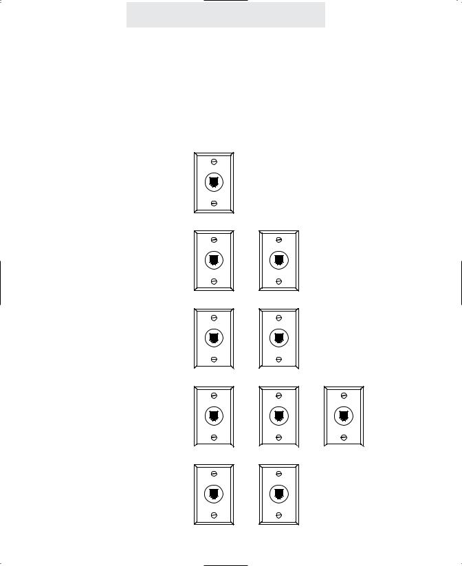
Installing Your System
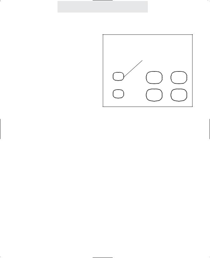
Step 1: Identify Your Existing Wiring System
In order for you to properly connect your EPIC System to an existing wiring system, it is important that you understand its configuration. The following are the most common multiple line situations. They consist of either one or both types of standard telephone jacks: The RJ11 Single Line Jack and the RJ14 Double Line Jack. Your system should match one of them.
2 incoming lines with
1 wall jack
2 incoming lines with
2 wall jacks
3 incoming lines with
2 wall jacks
3 incoming lines with
3 wall jacks
4 incoming lines with
2 wall jacks
ix
Line 1-2 |
Line 1 |
Line 2 |
Line 1-2 |
Line 3 |
Line 1 |
Line 2 |
Line 3 |
Line 1-2 |
Line 3-4 |
Installing Your System
Step 1: Identify Your Existing Wiring System (Continued)
4 incoming lines with
3 wall jacks
4 incoming lines with
4 wall jacks
Line 1-2 |
Line 3 |
Line 4 |
Line 1 |
Line 2 |
Line 3 |
Line 4 |
Label the jacks at each location.
Identify and label the jacks at each location to avoid the possibility of improperly connecting any of the lines to the telephones. To do so, write the line number(s) directly on each jack plate with a felt-tip pen.
For example:
If you have difficulty in identifying wall jacks.
Call the vendor who installed the inside wiring and ask for assistance in identifying your existing wiring system and jacks.
If you are installing new wiring and jacks.
If any new telephone wiring and modular jacks need to be installed, and four lines are to be used, install two-line RJ14 jacks at each telephone location. Each RJ14 jack accommodates two telephone lines.
1

Installing Your System
Step 2: Plan Your Installation
Up to 16 Epic System telephones may be connected to form your office/home configuration. Each phone must be assigned a different station number, from 11 to 26.
IMPORTANT: Each Epic System telephone must be connected to the same Line 1 telephone number for proper operation. The remaining lines may or not be connected to each station as you desire.
Standard Installation:
Your Epic telephones come factory-set for a standard “Shared” installation, which is also called “square” in telephone terminology. This means that Line 1 is to be connected to the same Line 1 telephone number at all the stations, Line 2 is to be connected to the same Line 2 telephone number at all the stations, and so on for Lines 3 and 4.
This is the desired setup for most installations, and if this is how you will be connecting your Epic System, you do not need to change any of the line connection settings in the telephones. You need only connect the phones to the telephone lines, and then follow the instructions on page 9 to be sure that you have connected the telephone numbers in the same order to each station.
Installations with Private Lines, Auxiliary Lines, and Unconnected Lines:
You may wish to connect private lines to Lines 2, 3 or 4 at some or all of your telephones. A private line is a telephone number that is connected to only one of the Epic telephones, and is not shared with any other station. You may also wish to connect auxiliary lines to Lines 2, 3 or 4 at some of your telephones. An auxiliary line is a telephone number that is shared by two or more stations, but which is a different telephone number than the corresponding line at the other stations.
These sort of installation requirements are common in Centrex environments, or in companies where clusters of telephones share common lines. In addition you may wish to leave some lines unconnected at some stations.
If your installation has any of these requirements, carefully fill out the worksheet on the following page and use it as a guide as you connect the telephone lines to your Epic telephones, then follow the instructions on page 19 to properly set each line at each station.

Installation
Worksheet
Mark each line at each station as either Shared, Private, Aux, or Unconnected. Refer to page 19 if you are not sure of the meaning of these terms. Note that Line 1 must be “Shared” at all the stations, meaning that Line 1 must be connected to the same telephone number at all the stations.
IMPORTANT: If you have circled anything other than “Shared” on this worksheet, then after installing your phones according to this worksheet you must follow the instructions on page 19 to set each phone as you have marked on this worksheet.
Station
Number
Stn. 11
Stn. 12
Stn. 13
Stn. 14
Stn. 15
Stn. 16
Stn. 17
Stn. 18
Stn. 19
Stn. 20
Stn. 21
Stn. 22
Stn. 23
Stn. 24
Stn. 25
Stn. 26
User’s Name
or Telephone
Location
|
|
|
|
Line 2 |
|
|
|
|
|
|
Line 4 |
|
|||
|
Line 1 |
|
|
|
Line 3 |
|
|
|
|
||||||
Tel #____ |
Tel #___________ |
|
Tel #___________ |
|
|
Tel #___________ |
|
||||||||
|
Shared |
|
|
|
|
|
|
|
|
|
|
|
|
|
|
|
|
|
|
|
|
|
|
|
|
|
|
|
|
|
|
|
Shared |
Private |
Shared |
Private |
|
||||||||||
|
|
|
|
|
|
Shared |
Private |
|
|||||||
|
|
|
|
L2Aux1 |
|
|
|
L3Aux1 |
|
|
|
|
L4Aux1 |
L4Aux2 |
|
|
|
|
|
Unconnected |
|
|
Unconnected |
|
|
|
Unconnected |
|
|||
|
Shared |
|
|
Shared |
Private |
|
|
Shared |
Private |
|
|
|
Shared |
Private |
|
|
|
|
|
L2Aux1 |
|
|
|
L3Aux1 |
|
|
|
|
L4Aux1 |
L4Aux2 |
|
|
|
|
|
Unconnected |
|
|
Unconnected |
|
|
|
Unconnected |
|
|||
|
Shared |
|
|
Shared |
Private |
|
|
Shared |
Private |
|
|
|
Shared |
Private |
|
|
|
|
|
L2Aux1 |
|
|
|
L3Aux1 |
|
|
|
|
L4Aux1 |
L4Aux2 |
|
|
|
|
|
Unconnected |
|
|
Unconnected |
|
|
|
Unconnected |
|
|||
|
Shared |
|
|
Shared |
Private |
|
|
Shared |
Private |
|
|
|
Shared |
Private |
|
|
|
|
|
L2Aux1 |
|
|
|
L3Aux1 |
|
|
|
|
L4Aux1 |
L4Aux2 |
|
|
|
|
|
Unconnected |
|
|
Unconnected |
|
|
|
Unconnected |
|
|||
|
Shared |
|
|
Shared |
Private |
|
|
Shared |
Private |
|
|
|
Shared |
Private |
|
|
|
|
|
L2Aux1 |
|
|
|
L3Aux1 |
|
|
|
|
L4Aux1 |
L4Aux2 |
|
|
|
|
|
Unconnected |
|
|
Unconnected |
|
|
|
Unconnected |
|
|||
|
Shared |
|
|
Shared |
Private |
|
|
Shared |
Private |
|
|
|
Shared |
Private |
|
|
|
|
|
L2Aux1 |
|
|
|
L3Aux1 |
|
|
|
|
L4Aux1 |
L4Aux2 |
|
|
|
|
|
Unconnected |
|
|
Unconnected |
|
|
|
Unconnected |
|
|||
|
Shared |
|
|
Shared |
Private |
|
|
Shared |
Private |
|
|
|
Shared |
Private |
|
|
|
|
|
L2Aux1 |
|
|
|
L3Aux1 |
|
|
|
|
L4Aux1 |
L4Aux2 |
|
|
|
|
|
Unconnected |
|
|
Unconnected |
|
|
|
Unconnected |
|
|||
|
Shared |
|
|
Shared |
Private |
|
|
Shared |
Private |
|
|
|
Shared |
Private |
|
|
|
|
|
L2Aux1 |
|
|
|
L3Aux1 |
|
|
|
|
L4Aux1 |
L4Aux2 |
|
|
|
|
|
Unconnected |
|
|
Unconnected |
|
|
|
Unconnected |
|
|||
|
Shared |
|
|
Shared |
Private |
|
|
Shared |
Private |
|
|
|
Shared |
Private |
|
|
|
|
|
L2Aux1 |
|
|
|
L3Aux1 |
|
|
|
|
L4Aux1 |
L4Aux2 |
|
|
|
|
|
Unconnected |
|
|
Unconnected |
|
|
|
Unconnected |
|
|||
|
Shared |
|
|
Shared |
Private |
|
|
Shared |
Private |
|
|
|
Shared |
Private |
|
|
|
|
|
L2Aux1 |
|
|
|
L3Aux1 |
|
|
|
|
L4Aux1 |
L4Aux2 |
|
|
|
|
|
Unconnected |
|
|
Unconnected |
|
|
|
Unconnected |
|
|||
|
Shared |
|
|
Shared |
Private |
|
|
Shared |
Private |
|
|
|
Shared |
Private |
|
|
|
|
|
L2Aux1 |
|
|
|
L3Aux1 |
|
|
|
|
L4Aux1 |
L4Aux2 |
|
|
|
|
|
Unconnected |
|
|
Unconnected |
|
|
|
Unconnected |
|
|||
|
Shared |
|
|
Shared |
Private |
|
|
Shared |
Private |
|
|
|
Shared |
Private |
|
|
|
|
|
L2Aux1 |
|
|
|
L3Aux1 |
|
|
|
|
L4Aux1 |
L4Aux2 |
|
|
|
|
|
Unconnected |
|
|
Unconnected |
|
|
|
Unconnected |
|
|||
|
Shared |
|
|
Shared |
Private |
|
|
Shared |
Private |
|
|
|
Shared |
Private |
|
|
|
|
|
L2Aux1 |
|
|
|
L3Aux1 |
|
|
|
|
L4Aux1 |
L4Aux2 |
|
|
|
|
|
Unconnected |
|
|
Unconnected |
|
|
|
Unconnected |
|
|||
|
Shared |
|
|
Shared |
Private |
|
|
Shared |
Private |
|
|
|
Shared |
Private |
|
|
|
|
|
L2Aux1 |
|
|
|
L3Aux1 |
|
|
|
|
L4Aux1 |
L4Aux2 |
|
|
|
|
|
Unconnected |
|
|
Unconnected |
|
|
|
Unconnected |
|
|||
|
Shared |
|
|
Shared |
Private |
|
|
Shared |
Private |
|
|
|
Shared |
Private |
|
|
|
|
|
L2Aux1 |
|
|
|
L3Aux1 |
|
|
|
|
L4Aux1 |
L4Aux2 |
|
|
|
|
|
Unconnected |
|
|
Unconnected |
|
|
|
Unconnected |
|
|||
|
Shared |
|
|
Shared |
Private |
|
|
Shared |
Private |
|
|
|
Shared |
Private |
|
|
|
|
|
L2Aux1 |
|
|
|
L3Aux1 |
|
|
|
|
L4Aux1 |
L4Aux2 |
|
|
|
|
|
|
|
|
|
|
|
|
|
||||
|
|
|
|
Unconnected |
|
|
Unconnected |
|
|
|
Unconnected |
|
|||
|
|
|
|
|
|
|
|
|
|
|
|
|
|
|
|
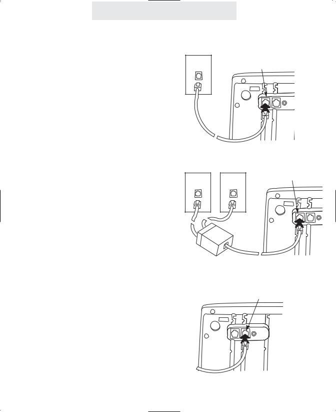
Installing Your System
Step 3: Install Desk/Table Top Phones
1 Connect First Line Cord |
Lines |
|
L1/L2 |
1&2 |
|
||
Connect one end of a long telephone line cord |
|
|
|
to the jack on the bottom of the telephone |
|
|
|
labeled L1/L2. Connect the other end to the |
|
|
|
jack(s) labeled Lines 1 & 2 either: |
|
|
|
directly to the wall jack if it is a two-line RJ14 |
|
|
|
jack |
|
|
|
OR |
|
|
|
to a two-line coupler (not provided) if you have |
Line 1 |
Line 2 |
L1/L2 |
two single-line RJ11 jacks for lines 1 and 2. |
|||
Then connect the two cords of the coupler to |
|
|
|
the corresponding wall jacks. Two-line cou- |
|
|
|
plers are available many places, for example |
|
|
|
Radio Shack (part #279-401). |
|
|
|
2 Connect Second Line Cord
Connect one end of a long telephone line cord |
L3/L4 |
to the jack on the back of the telephone labeled |
|
L3/L4. Connect the other end to the wall |
|
jack(s) labeled Lines 3 & 4 in the same manner |
|
as described in the previous step. |
|
Note: If you are installing a 3-line EPIC telephone, or are connecting a 4-line telephone to only 3 lines, connect the other end of the line cord directly to the wall jack labeled Line 3.
4
Installing Your System
Step 3: Install Desk/Table Top Phones (Continued)
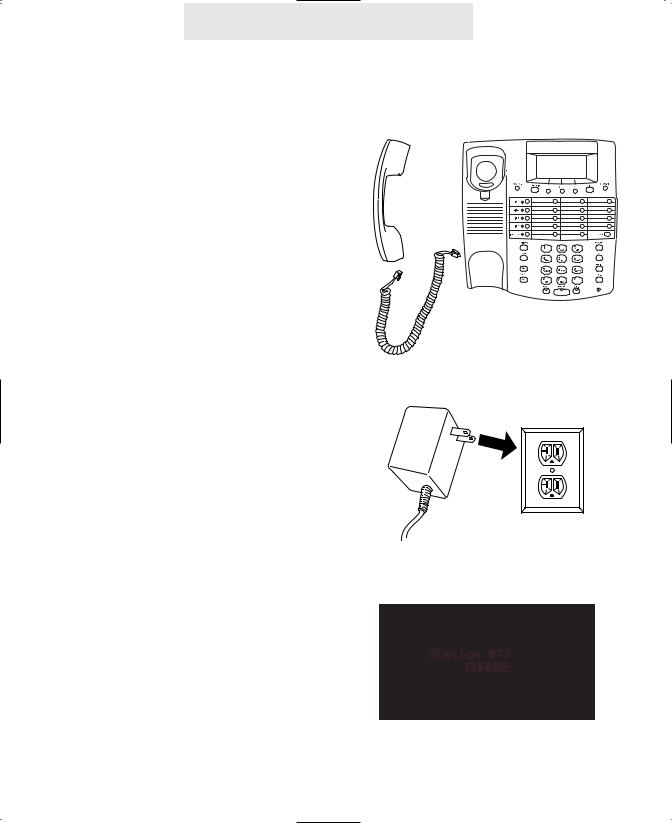
3 Connect Handset
Plug either end of the coiled handset cord into the handset and the other end into the jack on the side of the telephone. Place the handset in the cradle.
4 Connect Power Cord
Plug the AC power cord into the adapter jack on the bottom of the telephone. Thread the power cord into the recessed groove. Plug the AC adapter into an electrical outlet not controlled by a wall switch.
5 Assign a Station Number
Refer to page 8 for detailed instructions on assigning a station number.
6 Install a 9-Volt Battery (Optional)
It is not necessary for you to install a battery in your Epic telephone for it to function normally. In fact, a battery is not even needed to preserve your memory dial numbers in the event of a power failure. This is because all memory dial numbers are stored in a static memory which retains its contents even with no electrical power. The only purpose of having a battery installed is so that the telephone itself can function for up to two hours in the event of a power failure. You may wish to install a battery in at least one Epic phone for emergency operation, or have another standard phone available. If you wish to install a battery, refer to page 68 for detailed instructions.
7 Verify Proper Installation
IMPORTANT: Please remember to perform the procedure on page 9, after you assign each station number, to verify that each telephone is properly installed.
5
Installing Your System
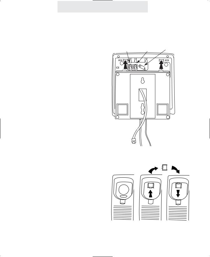
Step 4: Install Wall Mounted Phones
1 Connect Cords to Telephone
If the wall jack is labeled Lines 1 & 2, connect |
L1/L2 |
L3/L4 |
AC power cord |
the short telephone line cord to the jack on the |
|
|
|
telephone labeled L1/L2. If the wall jack is |
|
|
|
labeled Lines 3 & 4, connect the short cord to |
|
|
|
the jack on the telephone labeled L3/L4. |
|
|
|
Connect the long telephone line cord to the other line jack on the telephone and thread it through its long groove on the bottom of the phone, then plug the AC power cord into the adapter jack on the bottom of the telephone, threading the power cord through its long groove on the bottom of the phone.
Thread the short telephone cord through the square hole in the center of the wall mount bracket, and then attach the wall mount bracket to the base of the telephone.
2 Connect Cords to Wall
Connect the long telephone line cord to the jack by the baseboard, and plug the AC adapter into the nearest electrical outlet not controlled by a wall switch.
3 Reverse Handset Hook
Slide the telephone hook out of the cradle, rotate it 180 degrees so that its tab faces upward, and then slide it back into the cradle.
4 Connect Handset
Plug either end of the coiled handset cord into the handset and the other end into the jack on the side of the telephone. Place the handset in the cradle.
6

Installing Your System
Step 4: Install Wall Mounted Phones (Continued)
5 Assign a Station Number
Refer to page 8 for detailed instructions on assigning a station number.
6 Install a 9-Volt Battery (Optional)
It is not necessary for you to install a battery in your Epic telephone for it to function normally. In fact, a battery is not even needed to preserve your memory dial numbers in the event of a power failure. This is because all memory dial numbers are stored in a static memory which retains its contents even with no electrical power. The only purpose of having a battery installed is so that the telephone itself can function for up to two hours in the event of a power failure. You may wish to install a battery in at least one Epic phone for emergency operation, or have another standard phone available. If you wish to install a battery, refer to page 68 for detailed instructions.
7 Attach Telephone to Wall
Hold the telephone close to the wall and connect the short telephone line cord to the jack. Then mount the telephone to the wall plate, sliding it down firmly so that it locks securely in place.
8 Verify Proper Installation
IMPORTANT: Please remember to perform the procedure on page 9, after you assign each station number, to verify that each telephone is properly installed.
7

Until a telephone is assigned a station number, the telephone will not operate, and the display will read “Station #??”. To assign this telephone a station number, simply press the soft key under CHANGE repeatedly until the desired station number is displayed.
It is important to connect the telephone to the telephone lines before pressing CHANGE, so that the phone can check other existing stations in the system, and avoid offering you a duplicate station assignment.
Note: One phone in the system must be set as Station #11 in order for all the system features, such as shared directory dial, to function.
Using Station Names
If you wish, you may also assign your station a name (See page 57). Then, people will see your station’s name when you call them on the intercom.

Installing Your System
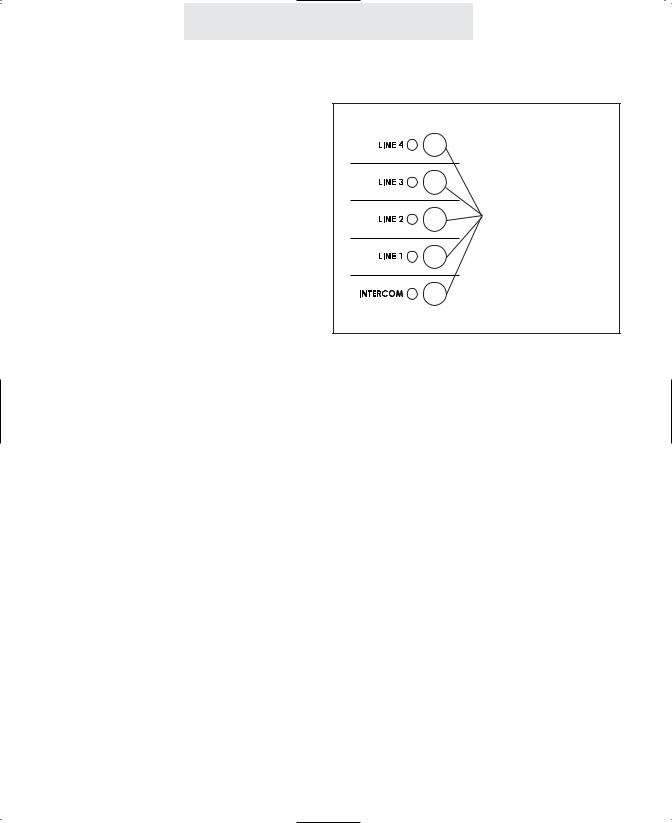
Verifying Proper Installation
The following procedure should be used at each telephone to verify proper installation. Also use this procedure any time you are experiencing difficulty, to test system configuration and identify possible system connection errors. The phone must be connected to the AC power supply, line 1 must be connected to the line 1 jack, and the phone must have been assigned an intercom station number.
IMPORTANT: If you ever have a problem with the installation or use of your EPIC System, please check the following procedure before calling our toll-free customer support number for assistance - 1-800-TMC-1638.
First, verify that line 1 is connected to the same telephone number at all the telephones. Do do this, press the line 1 button at one of the telephones. The line 1
LED should be green, the speakerphone LED should be red, and dial tone should be heard from the speaker. Now go to each of the other stations and make sure that each line 1 LED is red.
Next, make sure that lines 2, 3 and 4 are connected the same at all the phones by following the following steps at each telephone:
1.Press the line 1 button. The line 1 LED should be green, the speakerphone
LED should be red, and dial tone should be heard from the speaker.
2.Dial the telephone number for line 2. The line 2 LED should flash slowly. If the line 2 LED does not flash, then line 2 is improperly connected to this telephone.
3.If this telephone utilizes line 3 and/or line 4, repeat steps 1 and 2, substituting the respective phone number(s) in step 2.
9

Setting Up Your System
Setting Up Your System At A Glance
The following must be done at each station:
Program |
Factory Setting |
Page |
Station Number |
Not assigned |
8 |
Assignment |
|
|
Automatic Line Selection |
Line 1 |
12 |
Set Distinctive Ringing |
None Set |
13 |
Toll Restriction |
No Restrictions |
14-17 |
Set up and Private, |
None Set |
19 |
Auxiliary, and |
|
|
Unconnected Lines |
|
|
Set Ringers |
All Ringers On |
22 |
On/Delayed/Off |
|
|
Select Intercom Ring, |
Handsfree |
54 |
Voice or Handsfree |
|
|
|
|
|
Note: You must program a feature only if you wish to change its setting from the
Factory Setting.
10
Setting Up Your System
Setting Up Your System At A Glance (Continued)
The following must be done at Station #11:
Program |
Factory Setting |
Page |
Set Toll Restriction |
“1234” |
14 |
Access Code |
|
|
Set System Call Privacy |
On |
18 |
On/Off |
|
|
Tone or Pulse Dialing |
Tone |
24 |
Store Shared Directory |
None Stored |
47 |
Dial Numbers |
|
|
Name Stations |
None Named |
57 |
|
|
|
Note: You must program a feature only if you wish to change its setting from the
Factory Setting.
11
Setting Up Your System
Setting Automatic Line Selection
To choose which line will be automatically selected:
1Press PROGRAM.
- The display will read “Program...”
2Press the soft key under NEXT repeatedly, until ”Auto Seize” appears in the display.
The display will show the current auto seize setting.
3Press the soft key under CHANGE repeatedly, until the desired auto seize setting is displayed.
The choices are:
Auto Seize:L1 (factory setting) Auto Seize:L2
Auto Seize:L3 Auto Seize:L4 Auto Seize:INTCM
4Press PROGRAM to exit.
You may choose any of the outside lines or the Intercom line to be selected automatically when you lift the handset or press the SPEAKER button
This feature allows you to choose which line will be selected automatically when you lift the handset or press the SPEAKER button.
You may choose any of the outside lines or the Intercom line. If your chosen line is in-use, the telephone will automatically select the next available line.
Note: An incoming call that is ringing at your telephone will be selected automatically when you lift the handset or press the SPEAKER or HEADSET button, regardless of the choices you have made for automatic line selection.
If you wish to select a different line while your phone is ringing, you must press the desired LINE button before lifting the handset.
12

Setting Up Your System
Setting Distinctive Ringing
To assign distinctive rings to one or more lines:
1 Press PROGRAM.
All lines are initially set to ring with Ring Sound #1. If you prefer, you may assign each outside line one of seven other distinctive ringer tones.
- The display will read “Program...”
2Press the soft key under NEXT repeatedly, until ”Distinctive Ring” appears in the display, and then press ENTER
The display will show the distinctive ring setting for Line 1.
3Press the soft key under CHANGE repeatedly, until the desired distinctive ring setting for Line 1is displayed.
The choices are:
L1:RING SOUND #1 (factory setting) through RING SOUND #8
4Press the soft key under NEXT to see the current setting for Line 2, and repeat steps 3 and 4 to change the settings for Lines 2-4.
5Press PROGRAM to exit.
Note: At any time when you have a particular distinctive ring setting displayed, you may press the soft key under HEAR to hear an example of that distinctive ring.
This feature is usually used in one of four ways:
1You may want to assign one of your lines its own ring tone and leave the other lines set at the default ring. For example, if line 3 were a private line at your telephone, you may assign it a distinctive ring so you could easily recognize calls ringing on your private line.
2Or, you may want to assign a particular line the same distinctive ring at all of the stations. For example, if line 3 were the customer service line, you may assign line 3 the same distinctive tone at all the telephones so everybody could easily tell when this line was ringing.
3Another use of this feature would be to give all of the lines at your telephone the same distinctive ring so that you could easily tell when your particular phone was ringing and differentiate it from the ringing of other nearby telephones.
4Or, you might give all of your lines the same distinctive ring simply because you prefer that particular ringing tone.
13

Setting Up Your System
Setting Up Toll Restriction
To set the system’s toll restriction access code:
At Station #11:
1Press PROGRAM.
-The display will read “Program...”
2Press the soft key under NEXT repeatedly, until “Toll Restriction” appears in the display, and then press ENTER.
-The display will read “Access Code:****.”
3Press the soft key under CHANGE if you wish to store a new access code.
4Enter a 4 digit number.
5Press PROGRAM to exit.
The Toll Restriction feature enables you to control outgoing calls and helps you prevent unauthorized long distance calls.
The toll restriction access code is set at station #11. This code is needed when you wish to change any toll restriction settings or when you wish to turn toll restriction on or off at a particular phone. (See page 40).
If you ever forget the access code, simply set a new code at Station #11. Until you set the access code, the code will be the one set at the factory, which is “1234”.
Setting the restricted numbers and the allowed exceptions at a particular telephone:
Follow the instructions on the following three pages for setting toll restrictions at particular phones. After you set a phone’s toll restrictions, the settings will not be erased, even in the event of a power failure. So you do not need to worry about ever having to re-enter the toll restriction settings at any of the stations. If you ever do wish to erase all the toll restriction settings stored at a particular phone, follow the instructions on page 49.
Turning toll restriction on/off at a particular telephone:
|
Follow the instructions on page 40 for turning |
|
toll restriction on and off at a particular phone. |
|
Note: After setting a station’s restrictions, its toll |
|
restriction is automatically ON. In the future, you |
|
may temporarily override its toll restriction or turn |
|
its toll restriction off for a longer period without |
14 |
affecting the settings stored in the telephone. |
|

Setting Up Your System
Setting Up Toll Restriction (Continued)
To set the restricted numbers at a particular telephone:
1Press PROGRAM.
-The display will read “Program...”
2Press the soft key under NEXT repeatedly, until “Toll Restriction” appears in the display, and then press ENTER.
-The display will read “Enter Code:”
3Enter the 4 digit toll restriction access code which was set at Station #11 (See preceding page).
-You will hear a confirmation beep and the display will read “Set Restricted #”
Toll restriction numbers are set individually at each station, so the restrictions can vary from phone to phone.
Some examples of popular restrictions:
“1” ... to restrict all numbers starting with “1”. “01” ... to restrict all international calls.
“0” ... to restrict all operator-assisted calls. “#976” ... to restrict all “0976” and “1976” calls. (When you enter restricted numbers, “#” is a wildcard that stands for the number “0” or “1”.) Note: Restrictions are usually just a few digits, since they prevent the dialing of all numbers starting with those digits.
Use the Worksheet below to plan your choice of restricted numbers. If you plan to set any stations with a different set of restrictions, then use additional copies of this worksheet.
4Press ENTER
-The display will show the currently stored Restriction #1, or indicate “1: ” if there is no Restriction #1 yet stored.
5Press the soft key under CHANGE if you wish to store a new Restriction #1, then dial desired restricted number, up to 6 digits.
6Press the soft key under SAVE.
7Press the soft key under NEXT and repeat steps 5-6 if you wish to store any additional restrictions at this phone.
Worksheet
|
|
|
|
|
|
|
|
|
|
|
|
|
|
|
You can set as |
Enter the restricted numbers |
|||||||||||
|
many as five |
|
exactly as you would dial them |
||||||||||
|
restricted numbers |
|
out. Each restriction can be up |
||||||||||
|
at each telephone. |
|
to 6 digits long. |
||||||||||
|
|
|
|
|
|
|
|
|
|
|
|
|
|
|
|
|
|
|
|
|
|
|
|
|
|
|
|
|
|
|
|
|
|
|
|
|
|
|
|
|
|
|
|
|
|
|
|
|
|
|
|
|
|
|
|
|
|
1st Restriction |
|
|
|
|
|
|
|
|
|||
|
|
|
|
|
|
|
|
|
|
|
|
|
|
|
|
|
|
|
|
|
|
|
|
|
|
|
|
|
|
2nd Restriction |
|
|
|
|
|
|
|
|
|||
|
|
|
|
|
|
|
|
|
|
|
|
|
|
|
|
|
|
|
|
|
|
|
|
|
|
|
|
|
|
3rd Restriction |
|
|
|
|
|
|
|
|
|||
|
|
|
|
|
|
|
|
|
|
|
|
|
|
|
|
|
|
|
|
|
|
|
|
|
|
||
|
|
4th Restriction |
|
|
|
|
|
|
|
|
|||
|
|
|
|
|
|
|
|
|
|
|
|
|
|
|
|
|
|
|
|
|
|
|
|
|
|
||
|
|
5th Restriction |
|
|
|
|
|
|
|
|
|||
|
|
|
|
|
|
|
|
|
|
|
|
|
|
15

Setting Up Your System
Setting Up Toll Restriction (Continued)
To completely restrict specific lines at a telephone:
1Press PROGRAM.
-The display will read “Program...”
2Press the soft key under NEXT repeatedly, until “Toll Restriction” appears in the display, and then press ENTER.
-The display will read “Enter Code:”
3Enter the 4 digit toll restriction access code which was set at Station #11 (See page 14).
-You will hear a confirmation beep and the display will read “Set Restricted #”
4Press the soft key under NEXT repeatedly, until “Line Restriction” appears in the display, and then press ENTER.
5Press the soft key under CHANGE repeatedly, until the desired Line 1 Restriction setting is displayed.
The choices are:
L1: NORMAL (factory setting) L1: RESTRICTED
6Press the soft key under NEXT to
In addition to setting specific restrictions at a particular phone (See preceding page), you may completely restrict any or all of the lines at a particular station.
People will not be able to make any outgoing calls on any lines that are completely restricted at a station, with the exception of the allowed numbers at that station and calls to “911”. However, they will still be able to receive incoming calls on these lines, take calls off hold, and have full use of the intercom.
The ability to completely restrict lines is useful in an office where you only want people to make calls on certain lines at particular stations. You may also wish to put one station in a public area, such as a lobby, and completely restrict all or most of its lines.
see the current setting for Line 2, and repeat steps 5 and 6 to change the settings for Lines 2-4.
7 Press PROGRAM to exit.
16

Setting Up Your System
Setting Up Toll Restriction (Continued)
To set the allowed numbers at a particular telephone:
1Press PROGRAM.
-The display will read “Program...”
2Press the soft key under NEXT repeatedly, until “Toll Restriction” appears in the display, and then press ENTER.
-The display will read “Enter Code:”
3Enter the 4 digit toll restriction access code which was set at Station #11 (See page 14).
-You will hear a confirmation beep and the display will read “Set Restricted #”
4Press the soft key under NEXT.
-The display will read “Set Allowed #”
5Press ENTER
-The display will show the currently stored Allowed #1, or indicate “1: ” if there is no Allowed #1 yet stored.
6Press the soft key under CHANGE if you wish to store a new Allowed #1, then dial desired allowed number, up to 10 digits.
7Press the soft key under SAVE.
8Press the soft key under NEXT and repeat steps 6-7 if you wish to store any additional allowed numbers at this phone.
If you set restrictions at a particular phone, you will most likely also want to store some allowed exceptions at that telephone.
For example, if you restrict long-distance calls, you will probably want to store some allowed area codes, such as “1301”. Or, for example,
you may wish to store “1800”, to allow all “1800”
calls. Or “1*******” to allow all “1+7 digit” calls.
(When you enter allowed numbers, “*” is a wildcard that stands for any number from 0-9.) You may also want to store some specific allowed numbers, for example other company offices.
Use the Worksheet below to plan your choice of allowed numbers. If you plan to set any stations with a different set of allowed numbers, then use additional copies of this worksheet.
Worksheet
|
|
|
|
|
|
|
|
|
|
|
|
|
||||
|
You can set as |
Enter the allowed numbers |
||||||||||||||
|
many as five |
|
exactly as you would dial them |
|||||||||||||
|
allowed numbers |
|
out. Each allowed number can |
|||||||||||||
|
at each telephone. |
|
be up to 10 digits long. |
|||||||||||||
|
|
|
|
|
|
|
|
|
|
|
|
|
|
|
|
|
|
|
|
|
|
|
|
|
|
|
|
|
|
|
|
|
|
|
|
|
|
|
|
|
|
|
|
|
|
|
|
|
|
|
|
|
|
|
|
|
|
|
|
|
|
|
|
|
|
|
|
|
|
1st Allowed |
|
|
|
|
|
|
|
|
|
|
|
|||
|
|
|
|
|
|
|
|
|
|
|
|
|
|
|
|
|
|
|
|
|
|
|
|
|
|
|
|
|
|
|
|
|
|
|
|
2nd Allowed |
|
|
|
|
|
|
|
|
|
|
|
|||
|
|
|
|
|
|
|
|
|
|
|
|
|
|
|
|
|
|
|
|
|
|
|
|
|
|
|
|
|
|
|
|
|
|
|
|
3rd Allowed |
|
|
|
|
|
|
|
|
|
|
|
|||
|
|
|
|
|
|
|
|
|
|
|
|
|
|
|
|
|
|
|
|
|
|
|
|
|
|
|
|
|
|
|
|
||
|
|
4th Allowed |
|
|
|
|
|
|
|
|
|
|
|
|||
|
|
|
|
|
|
|
|
|
|
|
|
|
|
|
|
|
|
|
|
|
|
|
|
|
|
|
|
|
|
|
|
||
|
|
5th Allowed |
|
|
|
|
|
|
|
|
|
|
|
|||
|
|
|
|
|
|
|
|
|
|
|
|
|
|
|
|
|
17
Setting Up Your System
Setting System Call Privacy On/Off
To set system call privacy on/off:
At Station #11:
1Press PROGRAM.
-The display will read “Program...”
2Press the soft key under NEXT repeatedly, until “Advanced Setting” appears in the display, and then press ENTER.
3Press the soft key under NEXT until “Call Privacy” appears in the display, and then press ENTER.
The display will show the current Call Privacy setting
4Press the soft key under CHANGE repeatedly, until the desired call privacy setting is displayed.
The choices are:
Call Privacy:ON (factory setting) Call Privacy:OFF
5Press PROGRAM to exit.
Note: Even if you set Call Privacy on, people will still be able to turn Call Privacy off during a call if they wish by pressing the CONFERENCE button. (See page 39)
If you set your system call privacy ON, you may still press the CONFERENCE button at any time during a call to release Call Privacy
The Call Privacy feature is set at Station #11, and this setting governs the entire system. There are two possible settings:
CALL PRIVACY ON: This is the initial factory setting and when this is set nobody can pick up their station and join or listen to your conversation unless you first release the call privacy by pressing the CONFERENCE button. This feature helps prevent eavesdropping and the disturbance of people accidentally interrupting your telephone conversations.
CALL PRIVACY OFF: This setting is useful for people who find the call privacy feature unnecessary or inconvenient. In some businesses, people prefer to be able to pick up other stations without the privacy having to be released first or having to be conferenced to the line.
Note: There is always call privacy on intercom calls regardless of your system call privacy selection. People at other stations cannot listen in to your intercom conversations.
18
 Loading...