

Page 1

CONTENTS
1 INTRODUCTION
2 PRECAUTIONS
3 INSTALLATION
3.1
AC Mains Supply
3.2 Audio Inputs
3.3
Unbalanced Line Inputs
3.4
Instrument Inputs
3.5
Insertion Points
3.6 Balanced Outputs
3.7
Unbalanced Output
3.8
Ventilation
4 OPERATION
4.1
Input Select
4.2
Input Gain
4.3 High Pass Filter
4.4 Phase Reverse
4.5 Pad
4.6 Phantom Power
4.7 Drive and Peak LEDs
4.8 Expander/Gate Section
4.9 Gate Threshold
4.10 Gate Attack and Release
4.11 Gate Meter
4.12 De-esser Section
4.13 De-esser Depth
4.14 De-esser Frequency
4.15 De-esser Bandwidth
4.16 De-esser Meter
4.17 Compressor Section
4.18 Comp. Threshold
4.19 Comp. Attack & Release
4.20 Comp. Ratio
4.21 Comp. Gain Make-Up
4.22 Comp. Knee
4.23 Comp. Opto Mode
4.24 Comp. Hold Mode
4.25 Equaliser Section
4.26 LF & HF Bands
4.27 LM & HM Bands
4.28 LM/HM Frequency
4.29 LM/HM Gain
4.30 LM/HM Bandwidth
4.31 EQ Pre
4.32 Stereo Link Operation
4.33 Ducking or Gating
4.34 Peak Output Limiter
4.35 Output Level
4.36 VU Meter
4.37 Digital Output Option
4.38 Bit Rate Select
4.39 Sampling Freq. Select
4.40 Digital Output Meter
4.41 Lock Status
4.42 Output Formats
4.43 Wordclock Input
5 USER TIPS / FAQs
6 SERVICE
7 SPECIFICATIONS
Page 2

1 INTRODUCTION
Congratulations on purchasing the VP-1 Mono Valve Processor from TL Audio.
The VP-1 combines classic Pentode and Triode valve techniques with Class A
discrete and solid state circuitry to produce a unit providing comprehensive facilities
for all aspects of single channel microphone and instrument pre-amplification and
processing.
The VP-1 features include:
- Class A discrete and Valve pre-amplification,
- Variable High Pass Filter,
- Expander / Gate,
- Vocal De-Esser,
- Fully variable Compressor with Transconductance and Optical modes,
- 4 band Parametric Equaliser,
- Variable Threshold Optical Limiter,
- Optional digital output, selectable up to 24bit, 96Khz.
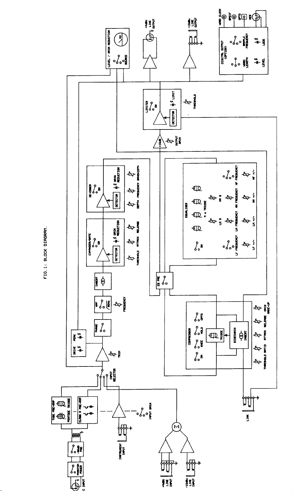
The block diagram of the VP-1 is shown in fig.1. There are four input sources:
microphone XLR, balanced line +4dBu XLR, unbalanced line -10dBu jack and front
panel instrument jack socket.
The mic input features switchable 48V phantom power and 30dB pad, and is
transformer coupled to both an all-valve pre-amp (consisting of pentode and triode
stages) and a class A discrete pre-amp, providing two of the options on the input
selector switch. The two line inputs are summed together for the third input selection,
with the instrument input available as the fourth selection. The instrument input is
front panel mounted for easy access, and is suitable for a variety of sources, including
guitar, acoustic pickup and keyboard. The input stage sensitivity for the mic and
instrument inputs is switchable in 10dB steps, followed by a +/-15dB trim control
effective on all inputs.
The input section also provides a continuously variable high pass filter to eliminate
unwanted LF noise from the input source, and a phase reverse switch. An insertion
point is provided immediately after the input section. The insertion point is
unbalanced, at a nominal operating level of -2dBu.
Page 3
Page 4

An expander/gate circuit is also included in the VP-1. The circuit provides variable
threshold and attack and release times, and includes a four segment LED bargraph to
indicate the gain reduction that is being applied.
De-essing of vocal sources is provided, with the depth (i.e. attenuation) of the deessing variable, along with frequency and bandwidth tuning to match the sibilant
content of the signal. This section also includes a four segment LED bargraph to
indicate the gain reduction that is being applied.
A comprehensive hybrid-valve compressor which can operate in either
transconductance mode (“voltage controlled resistance”) or optical mode (“light
dependent resistance”) is available to tailor the signal dynamics. The two modes each
provide effective compression, but with subtly different characteristics which may
suit particular source material. Hard or soft knee and optional hold switching further
augment the fully variable threshold, ratio, attack, release and gain make-up.
The VP-1 includes a four band equaliser, which utilises four triode valve stages. The
EQ may be switched to pre or post the compressor. The LF and HF bands are shelving
and feature switched frequencies, whilst the LM and HM bands are fully parametric
peaking stages with variable frequency and bandwidth. All bands have +/-15dB of cut
and boost.
The master level control is a large rotary fader, providing up to 15dB of gain. An
optical limiter with variable threshold and LED indication prevents the following
equipment from being overdriven by the VP-1.
Line level outputs are provided at +4dBu nominal level via a balanced XLR
connector, and at -10dBu nominal level via an unbalanced jack socket. An optional
digital output module is available for the VP-1, providing various output formats,
word lengths and sampling rates.
The VP-1 metering consists of an illuminated moving coil VU meter which can
display input level, output level or compressor gain reduction. In addition, a variable
intensity yellow “drive” LED indicates the signal level through the valve stages, and a
red “peak” LED monitors the headroom remaining on the input and post processed
signals.
Please read this manual fully before installing or operating the processor.
Page 5

2 PRECAUTIONS
The TL Audio VP-1 processor requires very little installation, but like all electrical
equipment, care must be taken to ensure reliable, safe operation. The following points
should always be observed:
- All mains wiring should be installed and checked by a qualified
electrician,
- Ensure the correct operating voltage is selected on the rear panel
before connecting to the mains supply,
- Never operate the unit with any cover removed,
- Do not expose to rain or moisture, as this may present an electric
shock hazard,
- Replace the fuse with the correct type and rating only.
Warning: This equipment must be earthed.
3 INSTALLATION
3.1 AC Mains Supply.
The equaliser is fitted with an internationally approved 3 pin IEC connector. A
mating socket with power cord and mains plug is supplied. All mains wiring should
be performed by a qualified electrician with all power switched off, and the earth
connection must be used.
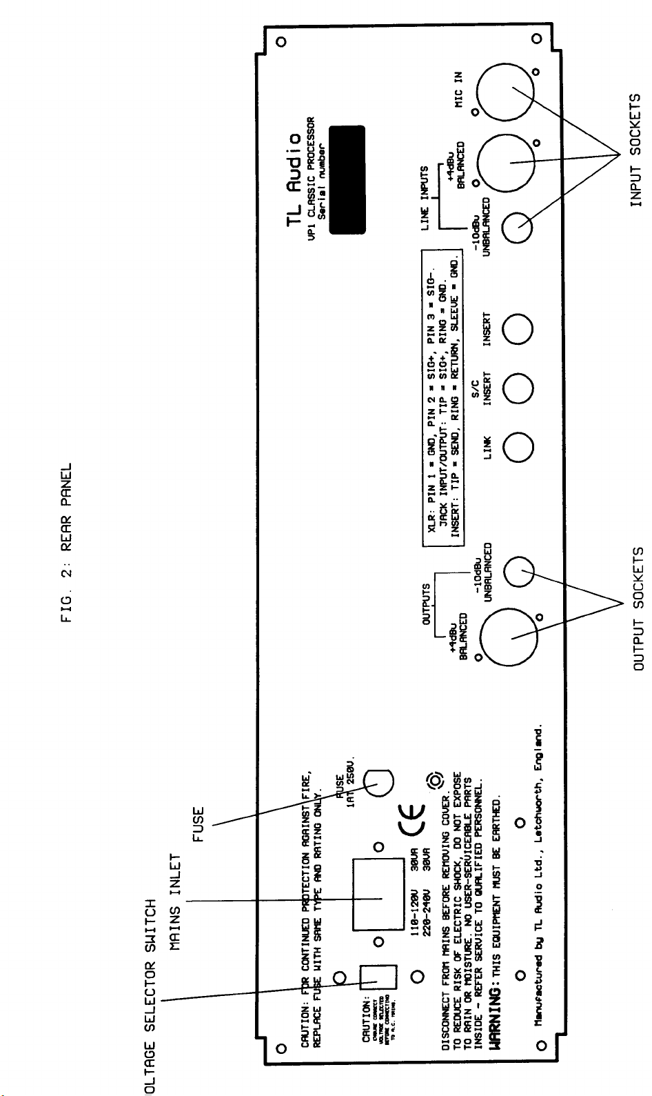
Please note that when using this unit with alternate supply voltages (in foreign
countries, for example) the position of the voltage selector switch on the rear of the
unit may need adjusting. The unit may be set for 115V (accepting voltages in the
range 110V to 120V, 60Hz AC) or to 230V (for voltages in the range 220V to 240V,
50Hz AC). The setting may be adjusted by inserting a small flat bladed screwdriver
into the slot of the switch, and sliding the switch to the left (for 115V) or to the right
(for 230V).
Alternate supply voltages may also require a different power cable or mains plug. If in
doubt, consult local electrical regulations.
Warning: attempted operation on the wrong voltage setting, or with an
incorrect fuse, will invalidate the warranty.
Page 6
Page 7

3.2 Audio Inputs.
The VP-1 has two female, 3 pin XLR connectors, for mic and line sources. Both are
compatible with either balanced or unbalanced signals, when the mating connectors
are appropriately wired:
Balanced inputs:
- Pin 1 = Ground (screen).
- Pin 2 = Signal Phase (“+” or “hot”).
- Pin 3 = Signal Non-Phase (“-” or “cold”).
Unbalanced inputs:
- Pin 1 = Ground (screen)
- Pin 2 = Signal Phase (“+” or “hot”).
- Pin 3 = Signal Ground.
When using unbalanced signals, the signal ground may be obtained by linking pins 1
and 3 in the mating XLR connector. Good quality screened cable should be used,
particularly for microphone or low level sources, to prevent signal degradation and
hum or noise pickup.
3.3 Unbalanced Line Inputs.
An unbalanced line level input is provided for each channel, on a 0.25” mono jack
socket. The mating plugs should be wired as follows:
- Tip = Signal Phase (“+” or “hot”).
- Screen = Ground.
3.4 Instrument Inputs.
A 2 pin (mono) jack plug is required, which should be wired as follows:
- Tip = Signal Phase (“+” or “hot”).
- Screen = Ground.
Page 8

Page 9

3.5 Insertion Points.
The insertion points are interfaced via a 3 pin, 0.25” switched jack socket on the rear
of the unit. The pin connections are:
- Sleeve = Ground,
- Tip = Send,
- Ring = Return.
The insertion points are unbalanced, and operate at a nominal level of -2dBu . If used
as an additional send only (e.g. as a send to a tape machine or monitor mixing desk),
the Tip and Ring should be wired together, to preserve the signal path through the
insertion point.
3.6 Balanced Output.
The +4dBu balanced output is via a balanced, 3 pin male XLR connector. The mating
connector should be wired as follows:
- Pin 1 = Ground (screen),
- Pin 2 = Signal Phase (“+” or “hot”),
- Pin 3 = Signal Non-Phase (“-” or “cold”).
If an unbalanced output is required from the XLR connector, pins 1 and 3 should both
be connected to ground.
3.7 Unbalanced Output.
An unbalanced line output at -10dBu is provided, on a 0.25” mono jack socket. The
mating connector should be wired as follows:
- Tip = Signal Phase (“+” or “hot”).
- Screen = Ground.
3.8 Ventilation.
The unit generates a small amount of heat internally, mainly due to the valve heaters.
This heat should be allowed to dissipate by convection through the grill in the front
panel, which must not be obstructed. Do not locate the processor where it will be
subject to external heating, for example, in the hot air flow from a power amplifier or
on a radiator.
Page 10

The VP-1 may be free standing, or mounted in a standard 19” rack where it will
occupy 3U of space.
4 OPERATION
4.1 Input Select.
The VP-1 is designed to accept mic, line and instrument signals, and the relevant
source is selected via a four position selector switch. The four positions are:
Valve - selects the microphone input as the signal source, and feeds the mic signal
through an all-valve preamp circuit.
Class A - selects the microphone input as the signal source, and feeds the mic signal
through a discrete class A solid state preamp circuit.
Line - selects the line input as the source signal.
Instrument - selects the front panel instrument input as the source signal.
4.2 Input Gain.
The Mic and Instrument gains are set simultaneously in 10dB steps by the rotary
switch, with fine adjustment available over an additional +/-15dB range from the trim
control. The total maximum gain available on the mic input is +65dB. The gain
available on the instrument input is 30dB lower than the mic, with a maximum of
+35dB.
The Line Input gain is set by the +/-15dB trim control only.
4.3 High Pass Filter (HPF).
The high pass (low cut) filter is a second order circuit (12dB per octave), with -3dB
points at the frequencies marked. The range of cut-off frequencies is fully variable
between 25Hz and 1kHz. The high pass filter is active on all inputs, and is ideal for
removing unwanted LF content from the input signal. Examples would be foot noise
and traffic rumble being picked up by a microphone, or excessive low frequency
response from a close mic’d source (known as the proximity effect). The filter is
bypassable and a status LED indicates when the filter is active.
4.4 Phase Reverse.
The phase reverse switch is used to invert the phase of the input signal, and like the
HPF is active on all inputs. This could be required when processing a signal that is
out of phase with other signals in a mix, in which case the resultant phase error
typically appears as a loss of low frequency signal content, due to cancellation of out
of phase components. If several VP-1s are used in a multi-microphone recording
situation then some phase cancellation may occur between microphones, which the
phase reverse switch will correct.
Page 11

4.5 Pad.
When activated, the pad switch will reduce the Mic input gain by 30dB. This is useful
when dealing with high level mic input signals, such as those produced when
recording loud sources with sensitive microphones (drums are a typical example).
Without the pad, it’s possible to overload the input stage in these circumstances,
causing audible distortion. Activating the pad switch will cure this.
4.6 Phantom Power.
This switch applies 48V phantom power to the mic input, allowing the VP-1 to be
used with condenser microphones.
CAUTION: Operation of the phantom power switch, or plugging a microphone in
with phantom power applied, may cause a click or thump in your loudspeakers. To
prevent this happening, ensure that the system gain is set to minimum (e.g. on your
mixing console fader or power amplifier), before operating the switch or plugging in a
microphone.
4.7 Drive and Peak LEDs.
The yellow Drive LED provides a visual indication of the signal level through the
valve stages, and therefore the extent of “warming” or valve character being
introduced. The drive LED will gradually illuminate as the input level or gain is
increased, over the range 0dB to +12dB.
The red Peak LED operates as a conventional warning that clipping is about to occur.
The operating level of both input and output stages is monitored, and the LED
illuminates when there is less than 5dB of headroom remaining.
If the output gain control is set to its centre position (0dB) then the Peak LED will
illuminate some 8dB after the Drive LED has reached its full intensity. However, it is
possible to add gain further down the chain (the output level control provides up to
15dB of gain), which will cause the Peak LED to illuminate at a lower level of Drive.
This situation implies that a high level of “clean” signal is present, without driving the
valves at a high level.
Normal operation would be to set the input gain so that the Drive LED is illuminating
regularly, with occasional illumination of the Peak LED occurring on loud transients.
4.8 Expander/Gate Section.
The Expander/Gate circuit is located post the preamp stage, just after the rear panel
insert point. The VCA based gate design is very precise and responsive, and operates
by monitoring the signal level and expanding the level down by around 80dB if the
signal is below the level selected on the rotary threshold control, effectively muting it.
Page 12

When the signal level returns to a level above the threshold, the gain is rapidly
restored to ensure that no transient edges are lost.
The Expander/Gate is perfect for removing unwanted background noise during quiet
periods of recording. A typical example would be removing the background noise,
breathing etc that occurs between vocal phrases when miking a singer. Setting the
threshold to a low level will cause the gate to open when the vocalist sings (i.e. when
the signal exceeds the threshold), after which the input signal falls back below the
threshold again. At this point the gate closes, and any low level background noise is
muted until the next vocal phrase. A similar technique can be use on any instrument
where unwanted spurious noise needs to be removed in between phrases.
4.9 Gate Threshold.
The Threshold control sets the signal level at which the gate starts to act, and is
continuously variable between -40dB and 0dB. Any incoming signals above the
threshold will pass through the gate unaffected, while those falling below the
threshold level will cause the gate to shut.
4.10 Gate Attack and Release.
The Attack time governs how quickly the gate opens in the presence of an audio
signal that has exceeded the threshold setting. The gate effectively fades the signal in
and ramps it up to its full value, with the attack time controlling the speed of fade-in.
The range of attack times is fully variable from 0.5mS to 10mS. The Release control
dictates how quickly the gate closes again once the signal drops below the threshold.
This works like a ramped fade-out, the release time setting the speed of the fade. The
range of release times is fully variable between 30mS and 300mS.
4.11 Gate Meter.
A four segment LED meter indicates the amount of gain reduction that the gate is
providing, and is calibrated from 10dB to 40dB - this meter only becomes active once
the gate section is engaged. A bypass switch allows the gate to be placed in and out of
circuit, allowing easy A/B comparison.
4.12 De-esser Section.
The de-esser stage employs high quality VCAs to allow effective but natural
reduction of sibilance, typically in vocal sources. The de-esser is effectively a
frequency conscious compressor stage, that reduces the gain of a user-selectable range
of frequencies. Sometimes sibilance can be reduced by judicious use of EQ (by
cutting the frequency at which sibilance is occurring), but other instances will demand
the use of a dedicated de-esser section.
4.13 De-esser Depth.
The Depth control sets the degree of de-essing effect - i.e the amount of gain
reduction applied, and is variable between 0 and 20dB.
Page 13

4.14 De-esser Frequency.
The Frequency control selects at which particular frequency the gain reduction is
made to occur, and covers the range 700Hz to 7kHz. Vocal sibilance normally occurs
in the range 3kHz to 5kHz, so it’s normal to set the Frequency control within this
range.
4.15 De-esser Bandwidth.
The Bandwidth control governs the broadness of the band of frequencies which are
affected by the de-esser. Selecting a very narrow bandwidth enables the user to hone
in on a tightly defined range of frequencies and effect only these - without upsetting
the rest of the frequency spectrum. A wider bandwidth will cause gain reduction to
occur on a broader spread of frequencies, and will thus be more pronounced in its
effect.
4.16 De-esser Meter.
Like the Expander/Gate, the De-esser has a dedicated LED meter that indicates the
amount of gain reduction occurring, between 1 and 14dB. This meter is only active
when the De-esser section is engaged. A bypass switch is provided to allow the Deesser to be switched in and out of circuit.
4.17 Compressor Section.
The VP-1 compressor stage is a very effective tool in controlling signal dynamics,
offering a range of sounds and very flexible control over compression parameters.
Valve compression is routinely used to limit the dynamic range of a signal, helping it
to sit correctly within a mix and lending fatness and warmth, particularly when
recording onto a digital medium.
The design of the compressor stage means that it’s possible to be quite extreme when
setting up the compression controls, since even when heavy gain reduction is
occurring the compressor maintains the quality of the source signal without
introducing unwanted side effects such as pumping, breathing and dulling of high
frequencies. Don’t be afraid to push the compressor hard with low thresholds and
high ratios!
4.18 Compressor Threshold.
The Threshold control is used to set the signal level at which the compressor starts to
act: incoming signals above the threshold will be compressed, those below will pass
through without any gain reduction occurring. The threshold control is calibrated
from +20dBu to -20dBu, resulting in increased compression as the control is rotated
clockwise and the threshold is lowered. Some compressor threshold controls work in
Page 14

the opposite direction, but our feeling is that as you turn the control ‘up’ it should
have more effect!
4.19 Compressor Attack and Release.
The attack time governs how quickly the compressor acts to ‘squash’ a signal that has
exceeded the Threshold, and is variable from 0.5msec to 50msec. At 0.5msec attack,
the compressor is fast enough to reduce the gain of a 1KHz signal in less than half a
cycle, effectively preventing an overload of any following equipment which has
limited headroom, such as a digital processor, tape machine or transmitter.
The release time sets how quickly the signal gain returns to normal once it has
crossed above the threshold again, and is variable from 40msec to approximately 4
seconds. Adjustment of the attack and release times allows unobtrusive compression
to be applied to virtually any audio signal, but should very short transients occur the
time constants become signal dependant, generally reduced, to prevent a slow release
leaving a “hole” in the signal after the transient. Also, a fast release setting will be
extended by a slow attack setting. Due to this automatic modification of the time
constants, the controls are simply calibrated “fast” to “slow”.
4.20 Compressor Ratio.
The Ratio controls the degree to which signals over the threshold are compressed, and
is expressed as a ratio of the input and output signals. For instance, a ratio of 1:3
means that for every increase of 3dB in the input signal, a 1dB increase in output
level results. Higher ratios result in a more highly compressed sound.
The ratio may be varied from 1:1.5 (very gentle compression) to 1:30 (near limiting).
The compressor normally operates with a “soft-knee”, i.e. the compression is
gradually introduced as the signal passes the threshold, in which case the ratio refers
to the compression eventually obtained.
4.21 Compressor Gain Make-Up.
When a signal is compressed its gain is reduced, and the gain make-up control allows
up to 20dB of extra gain to be applied to bring the level of the compressed signal up
to that of the original. This retains the subjective loudness of the signal, and allows
easy A/B comparisons of the original and compressed signals without a change in
level occurring when switching between the two.
4.22 Compressor Knee.
Page 15

This switch allows a choice of two compressor response types - Hard or Soft Knee.
Soft knee mode means that once the signal has exceeded the threshold, gain reduction
is introduced gradually, since the response curve of the compressor around the
threshold is gentle. This results in a more subtle and musical type of compression
effect. In “Hard Knee” mode, the curve is more severe, so that signals above the
threshold are “squashed” more aggressively. This yields a more audible and
pronounced compression effect.
4.23 Compressor Opto Mode.
The VP-1 offers two distinct and independent types of gain control circuit. The
normal mode employs the trademark TL Audio transconductance amplifier circuit, as
featured in many other TL Audio products, notably the C-1 compressor. This circuit
uses a solid state transconductance amplifier to accurately control gain, with a triode
valve stage in the gain make-up circuit to add warmth.
The VP-1 ‘Opto’ mode replaces the transconductance amplifier with an optical gain
control circuit, with the valve still active in the gain make-up circuit. The opto circuit
uses a LED/light dependent resistor device to control gain, which yields a slightly
more coloured sound with a slower response time. Many vintage compressors employ
opto designs, and its inclusion on the VP-1 allows a much wider palette of
compression sounds to be obtained.
4.24 Compressor Hold.
The Hold facility on the VP-1 delays the onset of release for approximately 10msec
after the input signal reduces below the threshold. This feature helps to reduce the
distortion commonly caused when using a compressor with a short release time to
process a low frequency signal, for example a bass guitar, where the compressor
attempts to modify the gain during each half cycle of the input waveform. If distortion
is experienced under these circumstances, activate the hold facility.
4.25 Equaliser Section.
The VP-1 boasts a four band valve EQ stage with low and high frequency shelving
and two fully parametric mid bands, giving an ideal combination of simplicity and
flexibility. Before switching the EQ into circuit, it is advisable to set the cut/boost
controls to their centre, or flat, position. The EQ is brought into circuit with the
overall “EQ-ON” push switch, signalled by a green LED. Like the compressor
section of the VP-1, the EQ stage can be pushed to quite extreme settings without
upsetting the tonal character of the signal. Many EQs can sound unpleasant and
unnatural when used in extreme ways, whereas the VP-1 positively relishes being
pushed hard.
4.26 LF and HF shelving bands.
Both the LF and HF bands offer four switched shelving frequencies:
LF shelving at 60Hz, 120Hz, 250Hz and 500Hz
Page 16

HF shelving at 2.2kHz, 5kHz, 8kHz and 12kHz
The EQ slopes have a second order 12dB/octave response, and the frequency values
are -3dB points. An associated gain control on both bands provides up to 15dB of cut
or boost on each selected frequency, controlling the full range of frequencies below
the LF corner frequency and above the HF corner frequency.
4.27 LM and HM parametric bands.
Both mid bands have fully parametric action, meaning that controls for frequency,
gain and bandwidth (Q) are provided. This allows a wide range of EQ possibilities
from general sweetening through to fairly drastic tonal surgery.
4.28 LM/HM Frequency.
This control sets the particular frequency to be cut or boosted, and is variable over the
following ranges:
LM: 30Hz to 3kHz
HM: 1kHz to 18kHz
Note that there is a good deal of overlap between the two bands, allowing extensive
control over the 1kHz to 3kHz midrange, which is often where corrective EQ needs to
be applied.
4.29 LM/HM Gain.
The gain control allows up to 15dB of cut or boost to be applied to the selected
frequency.
4.30 LM/HM Bandwidth. (Q)
This control governs the shape of the frequency response curve, specifically the width
of the band of frequencies to be cut/boosted. While the Frequency control sets the
centre frequency, the Q control regulates the broadness of the EQ curve either side of
this frequency. Narrow Q settings (about 7 at the minimum control position,
corresponding to about 0.15 octaves) result in sharp, narrow bandwidths generally
used for audio correction or effects. Intermediate settings, say 1 to 3, are generally
used to enhance or reduce a broader range of frequencies, typically to make an
instrument or vocal “stand out”, or recede, into the mix. Finally, low Q values (down
to about 0.7, or 1.5 octaves) provide more gentle contouring, or “sweetening” of the
response.
4.31 EQ Pre.
The EQ Pre switch reverses the order of the compressor and EQ in the signal path. In
normal operation, the signal will pass through the compressor before the EQ section,
Page 17

but the EQ Pre switch will route the signal through the EQ first. This can result in a
different tonal character, and also allows certain frequencies to be boosted ahead of
the compressor, resulting in a certain degree of frequency conscious action by the
compressor itself.
4.32 Stereo Link Operation.
Two VP-1s may be configured for stereo operation by inserting a Link cable between
the two units and activating the Link switch on both units. In this mode, the control
voltages of the two compressor sections are linked, as are the two limiter sections,
ensuring that the same amount of gain reduction is applied to both channels (even if
one signal is below the threshold). This ensures that the stereo image is preserved. In
this mode there is no ‘master’ or ‘slave’ as such - the unit causing the most gain
reduction will dictate how much compression is applied to the other linked unit. All
the controls on the two units still remain independent.
4.33 Ducking or Gating.
A variation on stereo operation as described above is master-slave operation, where
the gain of one VP-1 is controlled from another unit, but without reciprocal action.
This is useful where a voice channel input is required to reduce the gain of, for
example, background music when the microphone signal is present.
The link cable should be fitted, as for stereo operation, but the Stereo Link switch
should only be depressed on the “slave” VP-1 (the background music channel in the
example above). If the compressor is switched out on the master unit, gain reduction
will only occur on the slave unit. The threshold and ratio controls on the master VP-1
will determine the extent of the gain reduction in the slave unit.
4.34 Peak Output Limiter.
The VP-1 output limiter is an optical design that provides responsive yet natural
control of output peaks - making it ideal for preventing overload in digital recorders.
Digital recorders will distort in a very unmusical way when overloaded to any degree,
so an output limiter is an ideal way of preventing over-modulation occurring. The
limiter is programmed with a very high ratio, short attack time and longer release
time, resulting in a fast response “brick wall” action.
A threshold control allows the limiter threshold to be varied between 0 and 20dB, and
a bypass switch with status LED is also provided. An red ‘active’ LED illuminates
when the limit threshold is crossed, and this is always connected - even when the
limiter itself is bypassed - making it useful as an output peak indicator.
The limiter is positioned post the output level control, so the user can be confident
that any increase in output gain will be precisely controlled.
Page 18

4.35 Output Level.
This control acts much like the fader on a recording console, in that it regulates the
overall level produced at the VP-1’s line outputs. This makes it ideal when recording
direct to tape or hard disc, since it enables the level to tape to be precisely controlled.
The range of the control is from -∞ (i.e. complete attenuation) through to +15dB. This
extra output gain is perfect for digital recording since many digital recorders require
large input levels to fully modulate them - it’s not uncommon to have to input +18dB
to generate a 0VU reading on a digital recorder.
As detailed in the above section, the output limiter acts after the output level control,
so if the limiter is engaged then its threshold setting will have ultimate control over
final output level.
4.36 VU Meter.
The VP-1 is equipped with an illuminated VU meter, which via the four way meter
selector switch can be used to monitor input level, output level or compressor gain
reduction.
In output mode (“O/P”), the meter is calibrated for nominal level of +4dBu at the
balanced output = 0VU. Similarly, 0dB on the meter also corresponds to -10dBu at
the unbalanced output. However, should a very high output signal be required, for
example +18dBu for a digital tape machine, the meter will be fully modulated and
indicate full scale. This situation is catered for by the “O/P +10” position on the meter
selection switch, which attenuates the signal by 10dB before displaying it on the
meter. Thus 10dB should be added to the meter reading in this mode, i.e. a meter
reading of 0VU is equivalent to the normal level of +4dBu, plus 10dB, giving a signal
level of +14dBu.
In “I/P” mode the meter may be also be switched to indicate the input signal level
(post the pre-amplifier but pre the EQ and compressor), or the amount of gain
reduction (compression) applied by the compressor section (“G/R”). In G/R mode, if
the signal is below the threshold, the meter will read 0dB: i.e. no gain reduction is
occurring. As the signal passes through the threshold the meter will show a negative
value, indicating that gain reduction has started at the compressor stage. Note that the
gain reduction indicated is a measure of the degree of compression, and does not
include any gain make-up applied - nor does it indicate any limiter gain reduction that
may be occurring further down the signal chain.
4.37 Digital Output Option.
The VP-1 supports an optional digital output card (DO-1) which is fitted via the rear
panel. The DO-1 card provides AES/EBU, SPDIF and TOSLINK optical outputs,
plus a Wordclock input. The master section of the VP-1 provides front panel control
of the bit rate and sample rate, plus an LED indication of external lock and a bargraph
Page 19

meter monitoring digital output level. These related front panel controls and meters
will have no effect until the DO-1 card is fitted.
The DO-1 enables the VP-1 to directly interface with digital equipment that carries
these same format inputs, thus bypassing any A/D input stage.
4.38 Bit Rate Select.
A three position rotary switch enables the user to select whether a 16, 20 or 24 bit
word length is outputted by the DO-1’s digital outputs. The output is properly
dithered to the selected word length.
4.39 Sampling Frequency Select.
The DO-1 card is capable of generating a digital output at four different sampling
rates: 44.1, 48, 88.2 and 96kHz. These rates are selectable via a four position rotary
switch on the VP-1 front panel.
4.40 Digital Output Meter.
The output level generated by the DO-1 card is monitored via an 8 segment LED
ladder which registers levels from ‘SIG’ (signal present) through to digital CLIP,
which corresponds to a 0dBFS level sustained for several consecutive samples.
4.41 Lock Status.
The Lock LED will illuminate when the VP-1 is locked to an external clock source
connected via the rear panel Wordclock input, assuming that the rear panel switch is
set to ‘External’ and the correct sample rate is selected (see 4.43). At all other times
the VP-1 will be synced to its own internal clock.
4.42 Output formats.
The DO-1 card offers three separate output formats, all of which are active
simultaneously:
AES/EBU - a balanced pro format on 3 pin XLR, conforming to AES3 and
IEC60958-4 standard.
SPDIF - an unbalanced coaxial consumer style format on RCA phono, conforming to
IEC60958-3 standard.
Optical - offers an optical version of the SPDIF format on a TOSLINK optical
connector, with data conforming to IEC60958-3 standard.
4.43 Wordclock Input.
Page 20

A rear panel Wordclock Input is provided for connecting the VP-1 to an external
master clock source. An associated switch on the rear panel selects between external
synchronisation and internal clock. In external mode the front panel sample rate
selection switch is still active and needs to be set to match the frequency of the
incoming wordclock source.
The Wordclock input connector is a BNC-type terminated in 75 ohms.
5 USER TIPS AND FAQs
Q: Why have both Class A and Valve preamp stages?
A: The Valve preamp stage combines an input transformer with
pentode and triode valve stages to offer supreme warmth, while the Class A
input stage replaces the valve stages with a discrete transistor design, yielding
a cleaner, harder sound. Class A circuitry involves special voltage biasing of
the transistors to minimise crossover distortion, contributing to its clean
sound.
Q: How many valve stages are in the VP-1?
A: Seven. One EF86 pentode valve stage is located in the preamp section, as is
one triode valve stage. One triode valve stage is in the compressor gain makeup circuit, and four triode valve stages are utilised in the EQ stage - one per
band. All the triodes are ECC83/12AX7A types, and all the valve stages are
run from a 250V DC power supply.
Q: Is it better to leave the unit switched on all the time?
A: Doing this will avoid the typical 30 minutes warming up period that the unit
would normally require to settle, but will reduce the lifespan of the valves
since the valve heater will be on constantly. Most users would power off
between sessions but leave a suitable warming up period before use.
Q: How long will the valves last before they need replacing?
A: This very much depends on whether the unit is left powered up all the time
(see above) and whether the unit is moved around and subject to vibration.
We’d say the average lifespan in a static set-up would be three to four years.
Ageing valves will typically result in a loss of HF brightness and a lack of
definition in the sound.
Q: How do the two VP-1 insert points differ?
A: One insert point is positioned just after the preamp stage, but ahead of the
processing sections. This enables a clean feed to be taken directly from the
preamp output, and also allows another processing unit to be patched into the
signal path if required, much like a mixer insert point.
The sidechain insert point acts in an entirely different way, by permitting an
EQ to be patched into the compressor sidechain, allowing frequency conscious
compression to take place. Once the EQ is patched into the sidechain insert,
boosting a particular frequency on the EQ will effectively lower the
compressor threshold in that part of the spectrum, making it more sensitive at
Page 21

that frequency. This would be an alternative way of de-essing an input signal,
by setting the boosted EQ frequency to match that of the sibilance.
Q: Any tips on using the Expander/Gate?
A: With low level signals such as tape hiss, microphone self noise or even noise
from guitar amplifiers the gate will shut off these unwanted elements, but they
will be present - often loud and clear - when the required signal opens the gate.
This may not be a problem in a busy mix where the unwanted noise in the
signal is hidden by the other instruments, but in a minimal, sparse or exposed
recording the shutting on and off of the gate may be more noticeable than the
noise itself. Tape hiss is a good example of this as the listener will often be
unaware of the hiss until the point the hiss disappears when gated. Our advice
is to consider whether each individual signal really needs gating, rather than
routinely gating every signal in a mix.
Many engineers will use noise gates very cautiously when recording as there
is a danger of ‘clipping off’ the beginnings and endings of vocal phrases, for
example. Once the signals have been recorded, gating can be used with more
confidence as the signals are preserved on the recording, so you may want to
avoid gating (or apply less aggressive gating) when tracking, and wait until
mixdown to get serious with the gate!
It can be hard to set the gate threshold point for some signals as the signal
dynamics may vary too much. Because of this problem it can be much easier
to set the threshold point on signals that have a smaller dynamic range, such as
compressed signals.
Gating at higher levels can help to “tighten” instruments up. For example fine
tuning the gate threshold, attack and release controls for a bass guitar signal
can help it to sit more tightly with the drum parts. The attack and release
controls can also be used to effect drum parts. Snare drums can be clipped at
the front end with a slower attack time, or at the tail end with a quick release
setting. The gate can also be useful to clean up signals before recording to
samplers.
Q: Can you offer advice on using the De-esser?
A: To use the VP-1 De-esser, boost the depth and bandwidth to maximum, then
adjust the frequency to find the most effective reduction of the sibilance. You
can then reduce the depth and narrow the bandwidth to achieve the required
reduction of sibilance with the least audible degradation to the signal quality.
The De-esser can also be used to dynamically reduce certain frequencies for
other instruments: for example reducing “fret” noise on an acoustic guitar. The
EQ section of the VP-1 can be used to help identify the troublesome
frequencies - once found and noted, they can be set for reduction on the deesser section.
Q: How should I use the Limiter?
A: The limiter is designed to prevent overload in the equipment that the VP-1 is
Page 22

driving, by limiting the maximum output level that the VP-1 generates. A
0VU output reading on the VP-1 should read approximately -18dB on a digital
recorder input (using +4dB connections) although this will vary with different
recorders. If the limiter threshold is set to approximately +17dB this would be
just below the point where the digital recorder may overload, so would be a
useful threshold to limit the output of the VP-1. Note that the ‘Limit’ LED is
active even when the limiter is in bypass mode, thus acting as a useful output
peak indicator.
6 SERVICE
Should the processor require service, it must be taken or posted to an authorised
dealer with a description of the fault. Please retain the original packing for possible
future use, and ensure the unit is suitably protected during transit. The manufacturer
cannot accept responsibility for damage caused during transportation. Proof of
purchase date must be included if claiming service under warranty.
The processor is supported by a limited warranty for a period of one year from the
date of purchase. During this period, any faults due to defective materials or
workmanship will be repaired free of charge. The warranty excludes damage caused
by deliberate or accidental misuse, tampering, operation on the incorrect mains
voltage, or without the correct type and value of fuse fitted. It is the user’s
responsibility to ensure fitness for purpose in any particular application. The warranty
is limited to the original purchase price of the equipment, and excludes any
consequential damage or loss.
Please record the following details, and retain proof of purchase:
Serial Number.............................
Date purchased...........................
Dealer.........................................
Page 23

 Loading...