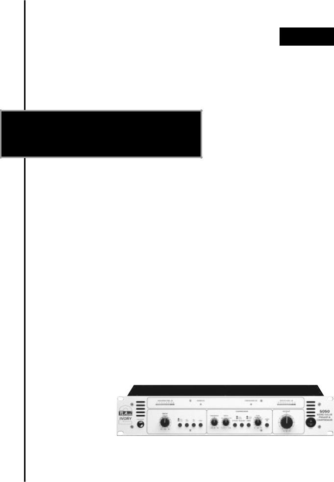
TL Audio 5050 User Manual

®
TLAudio
user manual
Ivory 2 Series
5050
MONO VALVE PREAMP & COMPRESSOR
TL Audio Ltd, Letchworth, Herts, SG6 1AN, UK
email: info@tlaudio.co.uk web: http://www.tlaudio.co.uk
CONTENTS
1INTRODUCTION
2PRECAUTIONS
3INSTALLATION
3.1A.C. Mains Supply
3.2Audio Operating Level
3.3Microphone Input
3.4Line Input
3.5Instrument Input
3.6Output
3.7Mounting
3.8Rear Panel
4 OPERATION
4.1Front Panel
4.2Input Selection
4.330dB Pad
4.4Phantom Power
4.5Microphone Input
4.6Line Input
4.7Instrument Input
4.8High Pass Filter
4.9What is Compression?
4.10Why Valve Compression
4.11Overview of Compressor Operation
4.12Threshold
4.13Ratio
4.14Attack & Release
4.15Knee
4.16Gain Make Up
4.17Compressor On
4.18Output Level
4.19Bar Graph Meters
4.20Optional DO-2 Digital Output Card
5 GETTING STARTED
5.1Connections
5.2In Use
6 SPECIFICATIONS

7 SERVICE
1.INTRODUCTION
Congratulations on purchasing the Ivory 5050 Mono Preamp & Compressor by TL Audio!
The Ivory 2 Series consists of a range of hybrid valve signal processors, which utilise low noise solid state electronics in conjunction with classic valve circuitry to produce audio processing units offering very high quality signal paths with the unique valve audio character. The Ivory 2 Series units offer comprehensive control facilities, whilst remaining straightforward to operate, and represent excellent value for money.
The 5050 is a single channel pre-amplifier, accepting a wide range of inputs, coupled to a compressor with fully variable parameters. Twin LED bargraph meters display output level and gain reduction. The optional DO-2 digital output card provides 24 bit A-D conversion of the 5050 analogue output, via a coaxial SPDIF connector. 44.1kHz and 48kHz sample rates are selectable, and an external BNC wordclock input is also provided on the D0-2.
The block diagram of the unit is shown in Fig.1. There are three input sources
- balanced microphone via an XLR connector, balanced line input via a TRS jack socket, and an instrument jack socket located on the front panel, where it provides a convenient means of patching a guitar or keyboard directly into the processor. The input stage is a hybrid valve circuit, containing one stage of an ECC83/12AX7A dual triode valve, run from a 150V DC stabilised supply. The input gain is governed by a centre-detented control, calibrated for 0dB nominal gain from the line input sources at the centre and providing up to 60dB of microphone gain. The instrument input is also controlled by the input gain potentiometer, and will accept a wide range of sources from passive pickups through to active guitars and keyboards. Phantom power and a 30dB pad are provided on the mic preamp stage, and a switchable 90Hz high pass filter is active on all three inputs.
The compressor stage offers variable control of threshold and ratio, with switchable attack & release times and a choice of soft or hard knee compression modes. The compressor is based around TL Audio’s trademark transconductance amplifier stage, and also utilises the other stage of the above-mentioned ECC83/12AX7A valve.
An independent gain make-up control is provided, to retain the subjective loudness of a compressed signal, plus an overall master output level control.
The output control has a nominal 0dB of gain at its centre, with up to 15dB of further gain available to achieve the high level required for some digital recorders.
The output is via a balanced jack socket at a nominal level of +4dBu. Metering of the output is by an 8 segment LED bargraph.
Please read this manual fully before installing or operating the 5050.
2.PRECAUTIONS
The T L Audio 5050 requires very little installation, but like all electrical equipment, care must be taken to ensure reliable, safe operation. The following points should always be observed:
-All mains wiring should be installed and checked by a qualified electrician,
-Ensure the correct operating voltage is selected on the rear panel before connecting to the mains supply,
-Never operate the unit with any cover removed,
-Do not expose to rain or moisture, as this may present an electric shock hazard,
-Replace the fuse with the correct type and rating only.
Warning: This equipment must be earthed.
3.INSTALLATION
3.1AC Mains Supply.
The unit is fitted with an internationally approved 3 pin IEC connector. A mating socket with power cord is provided with the unit, wired as follows:
Brown: Live.
Blue: Neutral.
Green/Yellow: Earth (Ground).
All mains wiring should be performed by a qualified electrician with all power switched off, and the earth connection must be used.
Before connecting the unit to the supply, check that the 5050 is set for the correct mains voltage. The unit is internally set for 110-120V 60Hz or 220-
240V 50Hz operation, and should only be changed by an authorised service centre. The mains fuse required is 20mm anti-surge, 1AT rated at 250V. If it is ever necessary to replace the fuse, only the same type and rating must be used. The power consumption of the equipment is 20VA.
Warning: attempted operation on the wrong voltage setting, or with an incorrect fuse, will invalidate the warranty.
3.2Audio Operating Level.
The 5050 is equipped with inputs and outputs suitable for connection to a wide variety of other audio equipment. The line level input is via a TRS jack socket, and will support both balanced and unbalanced operation when correctly wired. The output is also a TRS jack socket and will support both balanced and unbalanced operation.
3.3Microphone Input.
The microphone input is via 3 pin female XLR connector, suitable for balanced or unbalanced microphones. The mating connector should be appropriately wired as follows for balanced or unbalanced operation:
Balanced inputs:
-Pin 1 = Ground (screen).
-Pin 2 = Signal Phase (also known as “+” or “hot”).
 Loading...