

Page 1

T L Audio
User Manual
PA1 PENTODE PRE-AMPLIFIER
Tony Larking Professional Sales Limited,
Letchworth, England.
Tel: 01462 490600. International +44 1462 490600
Page 2

INTRODUCTION
The T L Audio Dual Pentode Pre-Amplifier is a very high quality, valve based
microphone and instrument amplifier. Transformer coupled microphone inputs and
front panel accessible instrument inputs are amplified by Pentode and Triode valve
stages with variable gain and switchable HF and LF filters. The output levels are
controlled by rotary faders, with headroom indicated by Signal, Peak and Clip LEDs.
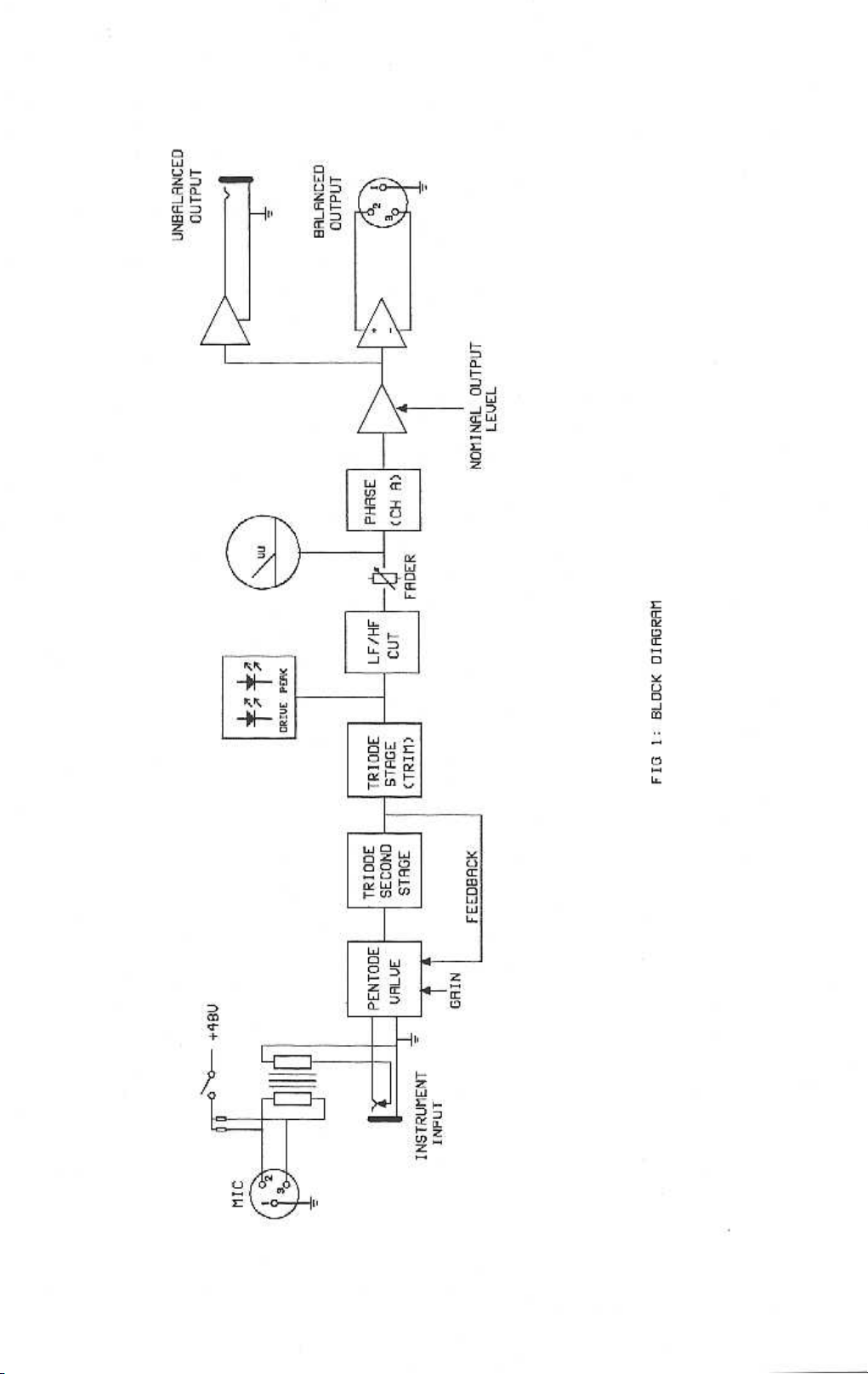
The block diagram of one of the channels is shown in fig.1. The microphone input is
balanced, suitable for low impedance (150-600 ohm) microphones and is transformer
coupled to the pentode first stage valve. The pentode valve type is the EF86, which
has been employed in many of the renown valve amplifier designs from the 1960’s
onwards, and which remains the first choice for a very low noise, high quality input
stage. A twin ECC83/12AX7 triode provides second stage gain plus variable trim built
around the third stage. The instrument input is via an unbalanced jack socket on the
front panel, bypassing the transformer, and is suitable for medium to high impedance
sources including active and passive guitars, and keyboards.
Gain control is switched in 10dB increments, from 20dB to 50dB, with the
continuously variable, centre-detented, trim control adding a further +/- 12dB. The HF
and LF Cut stages are second order passive filters which are switchable to Off (i.e.
maximum bandwidth), plus 3 frequencies per filter. Channel A is additionally
equipped with a phase reverse switch to ensure correct phase relation of an overall
stereo system.
A solid state, balanced output stage completes the signal path by providing a high
drive capability suitable for connection to virtually any mixing console, amplifier or
PA system. An unbalanced jack socket output and +4dBu / -10dBu nominal output
level switch are also provided.
Please read this manual fully before installing or operating the Pentode Pre-Amplifier.
Page 3
Page 4

PRECAUTIONS
The T L Audio Pentode Pre-Amplifier requires very little installation, but like all
electrical equipment, care must be taken to ensure reliable, safe operation. The
following points should always be observed:
- All mains wiring should be installed and checked by a qualified
electrician,
- Ensure the correct operating voltage is selected on the rear panel
before connecting to the mains supply,
- Never operate the unit with the cover removed,
- Do not expose to rain or moisture, as this may present an electric
shock hazard,
- Replace the fuse with the correct type and rating only.
Warning: This equipment must be earthed.
INSTALLATION
The rear panel connectors are identified in fig.2.
AC Mains Supply.
The Pre-Amplifier is fitted with an internationally approved 3 pin IEC connector. A
mating socket with power cord is provided with the unit, wired as follows:
Brown: Live.
Blue: Neutral.
Green/Yellow: Earth (Ground).
All mains wiring should be performed by a qualified electrician with all power
switched off, and the earth connection must be used.
Before connecting the unit to the supply, check that the voltage selector switch on the
rear panel is correctly set. The unit may be set for 115V (accepting voltages in the
range 110V to 120V, 60Hz AC), or to 230V (for voltages in the range 220V to 240V,
50Hz AC). The fuse required is 20mm anti-surge, 1AT.
Page 5

Warning: attempted operation on the wrong voltage setting, or with an
incorrect fuse, will invalidate the warranty.
Audio Inputs.
Each channel has a 3 pin XLR connector for the microphone input. It is compatible
with either balanced or unbalanced signals, when the mating connector is
appropriately wired:
Balanced inputs:
- Pin 1 = Ground (screen).
- Pin 2 = Signal Phase (“+” or “hot”).
- Pin 3 = Signal Non-Phase (“-” or “cold”).
Unbalanced inputs:
- Pin 1 = Ground (screen)
- Pin 2 = Signal Phase (“+” or “hot”).
- Pin 3 = Signal Ground
When using unbalanced signals, the signal ground may be obtained by linking pins 1
and 3 in the mating XLR connector. Good quality screened cable should be used,
particularly for microphone or low level sources, to prevent hum or noise pickup.
Unbalanced Instrument Inputs.
An unbalanced instrument input is provided for each channel, on a 0.25” mono jack
socket. The mating plugs should be wired as follows:
- Tip = Signal Phase (“+” or “hot”).
- Screen = Ground.
Page 6

Outputs.
The outputs are via balanced, 3 pin male XLR connectors. The mating connectors
should be wired as follows:
- Pin 1 = Ground (screen),
- Pin 2 = Signal Phase (“+” or “hot”),
- Pin 3 = Signal Non-Phase (“-” or “cold”).
If an unbalanced output is required, pins 1 and 3 should both be connected to ground.
The unbalanced jack socket outputs should have mating plugs wired as follows:
- Tip = Signal Phase (“+” or “hot”).
- Screen = Ground.
The nominal output level switch, located next to the balanced outputs, changes the
gain of the output stage to provide optimum signal to noise ratio and headroom when
the Pre-Amplifier is connected to professional equipment (+4dBu nominal) or semipro equipment (normally -10dBu).
Ventilation.
The unit generates a small amount of heat internally, mainly due to the valve heaters.
This heat should be allowed to dissipate by convection through the grill in the front
panel, which must not be obstructed. Do not locate the Pre-Amplifier where it will be
subject to external heating, for example, in the hot air flow from a power amplifier or
on a radiator.
Mounting.
The unit may be free standing or mounted in a 19” rack, where it will require 2U of
space.
Page 7

Page 8

OPERATION.
Front Panel.
The front panel controls are shown in fig.3.
Input Stage.
Ensure that the correct input connector, mic or instrument, is being used. Note that
the instrument input will override the mic input if both are connected at the same time.
+48V phantom power is available at the mic socket, selected by the switch adjacent to
the input socket.
CAUTION: Operation of the phantom power switch, or plugging a microphone in
with phantom power applied, may cause a click or thump in your loudspeakers. To
prevent this happening, ensure that the system gain is set to minimum (e.g. on your
mixing console fader or power amplifier), before operating the switch or plugging in a
microphone.
Gain.
The Mic gain is set in 10dB steps by the rotary switch, with fine adjustment available
over an additional +/-12dB range from the trim control. The total maximum gain
available on the mic input is +62dB. The gain available on the instrument input is
14dB lower than the mic, with a maximum of +48dB.
LF and HF Cut.
The filters are second order (12dB per octave), with -3dB points at the frequencies
marked. Each filter has 3 switched frequencies plus an “Off” position. With both
filters in the Off position, the Pre-Amplifier will produce a frequency response of 2dB at 30Hz and 40KHz.
Fader.
Each channel is equipped with a large, rotary fader for control of the output level. 0dB
output gain is obtained at the maximum clockwise position.
Page 9

Phase Reverse.
Channel A features a phase reverse switch, which may be used to correct a phase error
introduced elsewhere in a stereo signal path being processed by the Pre-Amplifier. A
phase error typically appears as a loss of low frequency signal content, due to
cancellation of out of phase components.
LED Level Indicators.
Each channel has a 3 segment LED meter to indicate the internal operating level of the
Pre-Amplifier. The meters monitor the pre-fade headroom level, illuminating at the
following points:
Signal: -20dBu,
Peak: +18dBu,
Clip: +24dBu (2dB of headroom remaining).
Page 10

Page 11

SPECIFICATIONS
Mic Input: Transformer balanced, input impedance greater than
1K5ohm, to suit 150-600 ohm microphones.
48V phantom power available, via switch.
Gain range +20 to +50dB.
Noise (EIN): -122Bu at maximum gain with a 150 ohm
termination, measured 22Hz-22KHz unweighted.
Maximum input level +6dBu.
3 pin female XLR connector.
Instrument Input:
Input impedance 50Kohm.
Nominal sensitivity for 0dBu output -35dBu.
Unbalanced jack socket input.
Outputs: Electronically balanced, unbalanced compatible.
Output impedance less than 10 ohms.
Maximum level +26dBu into 10Kohms, +22dBu into 600 ohms.
3 pin male XLR connector.
Unbalanced jack socket outputs,
Impedance 47 ohms,
Maximum level +20dBu into 10Kohms.
Nominal output level switchable +4dBu or -10dBu.
Frequency Response:
30Hz to 40KHz, +0, -2dB.
LF and HF Cut Filters:
Second order, 12dB per octave.
Distortion:
THD+N: 0.05% at 1KHz, mic input at 20dB gain, 0dBu output.
Page 12

Power Requirements:
Rear panel selectable for 220-240V 50Hz or 110-120V 60Hz
operation.
Rear panel fuse 20mm, 1AT.
Power consumption 30VA typical.
Detachable 3 pin IEC connector, mating connector and cable
supplied.
Front panel On/Off switch with green LED.
Dimensions:
19” rack mounting, 2U high.
483mm wide x 88mm high x 205mm deep.
Weight: 5.8Kg.
In line with a policy of continuous development, the above specifications are subject to change without
notice.
SERVICE
Should the unit require service, it must be taken or posted to an authorised dealer.
Please retain the original packing for possible future use, and ensure the unit is
suitably protected during transit. The manufacturer cannot accept responsibility for
damage caused during transportation.
The unit is protected by a limited warranty for a period of one year from the date of
purchase. During this period, any faults due to defective materials or workmanship
will be repaired free of charge. The warranty excludes damage caused by deliberate or
accidental misuse, operation on the incorrect mains voltage, or without the correct
type and value of fuse fitted. It is the user’s responsibility to ensure fitness for purpose
in any particular application. The warranty is limited to the original purchase price of
the equipment, and excludes any consequential damage or loss.
Please record the following details:
Serial Number.............................
Date purchased...........................
Dealer.........................................
 Loading...