

Page 1

CONTENTS
f.
CONGRATULATIONS!
INTRODUCTION 3
Block Diagram 5
PRECAUTIONS
INSTALLATION 7
AC Mains Supply 7
Audio Connections 8
Mic Inputs 8
Line Inputs 9
Insertion Points 9
Direct Output 10
Main Stereo Output 10
Monitor Outputs 10
Aux Outputs 11
Stereo 2T Returns 11
Effects Return 11
Headphone Outputs 12
Meter Calibration 12
Digital Modules 12
OPERATION 13
Input Selection 13
Input Gain Control 13
Line Input 13
Microphone Input 13
2
Phase Reverse 14
High Pass Filter 14
30dB Pad 14
Equalisation 14
Insertion Points 15
6
Aux Sends 15
Direct Output 15
Track Level Control 15
Pan Control 15
Mute Switch 16
PFL Switch 16
Channel Fader 16
Drive and Peak LEDs 16
Stereo Mix 16
Aux Masters 16
Effects Return 17
Monitor and 'phones Level 17
PFL Balance Level 17
2-Track Returns 17
Loudspeaker Mute 18
Metering 18
Digital Output Option 18
Wordclock Input 18
A Final Word! 19
SERVICE 20
SPECIFICATIONS 21
1
~
Page 2
CONGRA TULA TIONS!
Congratulations on you purchase of a TL Audio M 1 Tubetracker Mixer, the perfect
solution for the modem day studio. Anyone who has used or heard our outboard
equipment, will be familiar with its ability to create a warm, smooth, and clean sound
that can inject wonderful 'feel' into your recordings.
Our acclaimed VTC and M4 consoles have also now been accepted as a great
sounding must have in the professional recording environment, with many high profile
users. The Ml offers you the TL Audio quality, in a desk that is modular, yet more
compact and affordable than the VTC and M4 - and still offers you the same great
sound.
The M 1 Tubetracker is ideal for the home and project studio as well as broadcast and
recording applications where space is limited.
The Ml offers you quality valve mic preamps on each channel, 3 band musical EQ
with sweepable mid on each channel, 2 auxiliary sends per channel as well as effects
returns and alternate monitoring options!
It has been designed to maximise today's recording techniques, with the addition of an
optional ADA T interface for easy digital connection to your recording device and
software. It makes the perfect front end to any digital recording set up, taking away
that 'clinical, sterile' sound whilst adding warmth and depth to your recordingsgiving you the sound that you have been longing for.
The M I Tubetracker is compact in size and features all its connectors on the back of
the top panel for easy connectivity and quick cable changes!
Available in 8 and 12 channel options the Ml combines that classic valve sound with
modern functionality.
2
Page 3
INTRODUCTION
The T L Audio Ml Tube Console combines classic valve techniques with low noise
solid state circuitry to construct a mixing console offering high specification signal
paths with the unique valve sound quality. 8 or 12 input channels are provided, all with
mic and line inputs, switchable 48V phantom power, three band EQ, balanced
insertion send and return, 2 Aux sends, Pan and lOOmm Fader. Each channel also
features a balanced Direct Output, which is pre EQ and independent of the channel
fader.
Mixing is via balanced busses to valve mix amplifiers. The stereo output is controlled
by a stereo lOOmm fader, and monitored by illuminated moving coil VU meters. A
stereo effects return, two 2-track returns and independent headphone output complete
the monitoring facilities.
The M 1 Tube Console is an ideal compliment to a digital audio workstation, but may
also be used for direct to stereo recording, as outboard analogue EQ during mixdown,
and as a complete studio, stage or PA mixer. The console is table-top mounting and
supplied with a free standing power supply. There are no fans in either the power
supply or console.
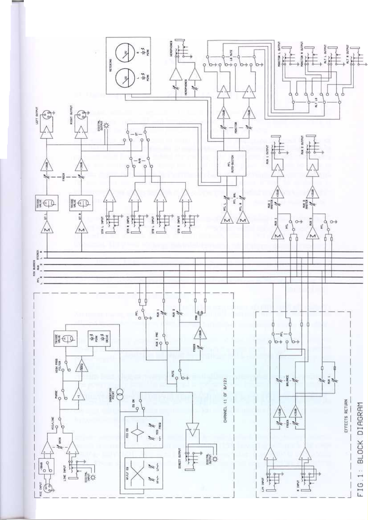
The block diagram of the M I Tube Console is shown in fig. 1. A discrete solid state,
electronically balanced input amplifier is used, to achieve state of the art performance
with very low noise, low distortion and wide bandwidth. The mic input is via an XLR
socket and is suitable for low impedance (150-600 ohm) microphones, with a gain
control range of + 16 to +60dB plus a 30dB pad. A front panel switch selects 48V
phantom power. The line input has an effective overall gain range of -20 to +20dB,
allowing the valve stages to be fully driven from line level signals in the range -20 to
+20dBu. The input stage is directly coupled to a second stage triode valve amplifier.
Increasing the gain at the input stage allows the unique overdriven valve sound to be
gradually introduced, as indicated by the "Drive" and "Peak" LEDs. Phase reverse and
90Hz high pass filter switches complete the input section.
A balanced insertion point is provided enabling the connection of external equipment
(a compressor, for example) into the channel. The insert send socket may also be used
as an independent output. The Direct Output from the channel is pre-fade and
balanced. It is taken after the valve stage, insertion point and EQ, but is unaffected by
the channel fader.
The equaliser section provides shelving LF and HF filters and swept frequency mid
peaking filter. The EQ stages may be bypassed for easy A-B comparison.
Mixing to the stereo bus is via 100mm linear faders with rotary pan control. PFL and
channel MUTE switches are also provided. Two Aux sends are available; Aux 1 is
switchab1e pre or post fade, with Aux 2 permanently post fade. The stereo return can
also send to Aux 1. The busses are balanced, with hybrid solid state / triode valve mix
3
Page 4

amplifiers on the stereo buss and solid state mix amplifiers on the Aux and PFL
busses. .
The monitoring outputs normally follow the stereo output, but may be switched to the
2 track return inputs, for example to check workstation outputs. Any PFL signal
automatically over-rides the monitor output. The PFL level relative to the stereo level
may be adjusted, and the overall monitor level is controlled by a high quality matched
pot with 29mm diameter knob.
Dual moving coil VU meters follow the monitor outputs. The meters are factory set for
OdB indication = +4dBu, but may be recalibrated using presets accessible from the
front panel.
The Aux outputs are controlled by master level controls, and the stereo effects return
provides a line level input, with gain and balance controls. All are equipped with PFL
switches.
Optional digital modules are available, providing multiples of 8 inputs and outputs for
the channel sections, plus the stereo main output.
Please read this manual fully before installing or operating the Ml Tube Console.
4
Page 5
Page 6
PRECAUTIONS
As with all electrical equipment, care must be taken to ensure reliable, safe operation
of your mixer. The following points should always be observed:
- All mains wiring should be installed and checked by a qualified electrician,
- The mixing console is heavy, and may require more than one person to
lift and place in position,
- Ensure the correct operating voltage is selected on the power supply
before connecting to the mains supply,
- Connect the power supply to the mixer before switching on,
- Never operate the mixer or power supply with any cover removed,
- Do not expose to rain or moisture, as this may present an electric
shock hazard.
- Replace the fuses with the correct type and rating only,
- Refer any service requirement to qualified personnel.
Warning: This equipment must be earthed.
Caution: Ensure adequate ventilation of the power supply and mixer.
Failure to observe these precautions may invalidate your warranty.
6
Page 7

AC Mains Supply.
The mixer should be placed on a solid, flat surface. Adequate ventilation must be
provided, with free space behind the cooling slots in the rear panel and immediately
above the ventilation slots along the top of the front panel. Care must be taken to
provide appropriate support for the mixer and the cables which will be connected to it.
Do not locate the mixer near a source of heat, or where it may be subjected to
interference from other electrical or radio frequency generating equipment (e.g. mobile
telephones).
Brown: Live.
Blue:
Neutral.
Green/Yellow: Earth (Ground).
All mains wiring must be performed by a qualified electrician with all power switched
off, and the earth connection must be used.
The power supply generates a certain amount of heat during use, which must be
allowed to dissipate from the ventilation slots in the sides of the unit. Never cover the
power supply or locate it near a source of heat, for example a radiator or power
amplifier.
7
Page 8

Warning:
Audio Connections.
Mic Inputs.
Balanced inputs:
attempted operation on the wrong voltage setting, or with an
incorrect fuse, will invalidate the warranty.
- Pin 1 = Ground (screen).
- Pin 2 = Signal Phase ("+" or "hot").
- Pin 3 = Signal Non-Phase ("-" or "cold").
Unbalanced inputs:
- Pin 1 = Ground (screen)
- Pin 2 = Signal Phase ("+" or "hot").
- Pin 3 = Signal Ground
8
Page 9

Line I~put.
A 3 pin, 0.25" jack plug is required, which is also compatible with balanced or
unbalanced sources, when wired as follows:
Balanced inputs:
- Tip = Signal Phase ("+" or "hot"),
- Ring = Signal Non-Phase ("-" or "cold"),
- Screen = Ground.
Unbalanced inputs:
- Tip = Signal Phase ("+" or "hot"),
- Ring = Ground,
- Screen = Ground.
Insertion Points.
The insertion points are also interfaced via 3 pin, 0.25" switched jack.
connections are:
The pin
- Tip = Signal Phase ("+" or "hot"),
- Ring = Signal Non-Phase C"-" or "cold"),
- Sleeve = Ground,
The insertion point is balanced, with send and return on separate jacks. A cable
inserted into the send socket only may be used as an additional output without
breaking the channel signal path. A cable inserted into the return socket will break the
insertion loop. The insertion sends and returns automatically adjust for balanced or
unbalanced connection.
9
Page 10

Direct Output.
The Track Output connector is a 3 pin, 0..25" jack socket. The output automatically
adjusts for balanced or unbalanced connection.
The mating connector should be wired as follows:
Balanced outputs:
Signal Phase ("+" or "hot"),
- Ring = Signal Non-Phase ("-" or "cold"),
- Screen = Ground.
Unbalanced outputs:
- Tip = Signal Phase (~~+" or "hot"),
- Ring = Ground,
- Screen = Ground.
Main Stereo Output.
The main outputs are via balanced, 3 pin male XLR connectors.
connectors should be wired as follows:
- Pin 1 = Ground (screen).
The mating
- Pin 2 = Signal Phase ("+" or "hot"),
- Pin 3 = Signal Non-Phase ("-" or "cold").
If an unbalanced output is required, pins 1 and 3 should both be connected to ground.
Monitor Outputs.
The monitor outputs are via balanced, 3 pin jack connectors. The mating connectors
should be wired as follows:
- Sleeve = Ground (screen),
= Signal Phase ("+" or "hot"),
- Ring
= Signal Non-Phase ("-" or "cold").
10
Page 11

If an unbalanced output is required, the sleeve and ring should both be connected to
ground.
Aux Outputs.
The Aux outputs are also via balanced, 3 pin jack connectors. The mating connectors
should be wired as follows:
- Sleeve = Ground (screen),
- Tip
- Ring
If an unbalanced output is required, the sleeve and ring should both be connected to
ground.
Stereo 2T Returns.
Two stereo inputs are provided to the monitor section, to allow off-tape monitoring,
etc. The inputs are via balanced, 3 pin jack connectors. The mating connectors should
be wired as follows:
= Signal Phase ("+" or "hot"),
= Signal Non-Phase ("-" or "cold").
- Sleeve = Ground (screen),
- Tip
- Ring
If an unbalanced signal is used, the sleeve and ring should both be connected to
= Signal Phase ("+" or "hot"),
= Signal Non-Phase ("-" or "cold").
ground.
Effects Return.
A stereo input is provided, for effects returns or other line level sources. The
connectors are 3 pin jack sockets, and the mating connectors should be wired as
follows:
- Sleeve = Ground (screen),
- Tip
- Ring
= Signal Phase ("+" or "hot"),
= Signal Non-Phase ("-" or "cold").
11
Page 12

If unbalanced signals are used, the sleeve and ring should both be connected to ground.
The right input of the return is norrnalled to the left input, allowing the left input to be
used a mono return.
Headphone Outputs.
The front panel jack socket is suitable for driving headphones of 32 ohms or higher
impedance. A standard 0.25" jack plug should be used.
Meter Calibration.
The meter "ovu" trims may be used to re-adjust the calibration of the VU meters if a
setting other than OVU = +4dBu is required. A steady signal of the desired line up
level should be applied, and a small screwdriver inserted through the front panel to
adjust the meter to the line up point on the scale.
Digital Modules.
Optional DO-8 digital modules are available for the MI. An 8 channel input/output
module may be fitted, providing a digital input which is normalled to the channel line
inputs (i.e. inserting an analogue input cable into the line socket will override the
digital input), plus digital outputs that follow the channel Direct outputs. When fitted
to the 12 channel version of the Ml, the digital input and output connections are to
channels 1 to 8 only. There is a separate DO-2 module available for the master section,
which provides the stereo output in digital format.
The specifications and user instructions for the digital modules are supplied separately.
12
Page 13

OPERATION
Input Selection
You must ensure that the correct input connector, mic or line, is being used from the
required source. You can select the type of input by pressing the 'LINE' switch at the
top right of each channel strip in or out. In the "up' position the mic input is selected;
depressing the 'LINE' switch selects the line input as the source. Note that you can
have mic and line inputs connected at the same time but will only be able to select a
single input at a time.
Input Gain Control
The gain control should be set to obtain the best signal to noise ratio, whilst preserving
adequate headroom. Any changes in gain level should be gradual to avoid sudden
overload or severe distortion. Extra care should be taken with higher level inputs, and
high gain settings should be used sparingly to avoid an increase in the noise floor and
the introduction of distortion.
Line Input
A typical line input will require less gain than a microphone signal as it is a 'hotter'
source. You should have the gain set to a minimum when connecting a line input, then
gradually increase it to achieve the required level.
Microphone Input
CAUTION: Operation of the phantom power switch, or plugging a microphone in
with the phantom power applied, may cause an audible click or thump in your
loudspeakers. To avoid this happening, ensure that the channel fader and stereo
master faders are set to a minimum before operating the switch or plugging in a
microphone. Switching between mic and line with high input gain settings may also
cause an audible thump if the level control is not turned down.
13
Page 14

Phase Reverse
The phase reverse switch is used to invert the phase of the input signal. It is active on
both mic and line inputs. This function could be required when processing a signal
that is out of phase with other signals in a mix, in which case the resultant phase error
typically appears as a loss of low frequency content, due to cancellation of out of phase
components. Phase reverse is commonly used when recording the bottom of a snare
drum (if also using a mic on top of the snare), the back of a guitar cab (if also
recording signal from the front of the cab), and when performing the stereo recording
technique known as an MS pair.
High Pass Filter
This low cut filter provides 12dB per octave of gain reduction with the -3dB point
being at 90Hz. Like the phase reverse switch, the high pass filter is active on both mic
and line inputs, and is ideal for removing low frequency rumble. The filter can be
useful in restricting 'popping' on vocals or even low frequencies caused by contact
with microphone stands or microphone cables. Popping is an undesirable thump that is
caused by close-miking certain spoken or sung letters, namely 'P' or 'B'. These
particular letters cause a sudden expulsion of air that can result in an audible thump.
As this thump has a lot of low frequency content the high pass filter can help to reduce
the problem, as can using a pop filter (a device usually made out of nylon material
similar to stockings) suspended in front of the microphone. The low cut filter is easily
bypassed for quick A/B comparison.
30dB Pad
Occasionally when using sensitive condenser microphones the source signal may be
too loud for the input preamp. In this situation, to avoid any overloading or distortion
of the mic preamp stage, the 30dB pad can be used to reduce the input gain to a more
manageable level. The 30dB pad only applies to the microphone input.
Equalisation
Before switching the EQ into circuit, it is advisable to set the cut/boost controls to
their centre, or flat, position. The EQ is brought into circuit with the 'EQ' push switch,
signalled by a green LED. Each channel has three bands of equalisation: shelving low
frequency (LF) (i.e. it extends from the selected frequency to the extreme low
frequency limit of the equaliser's response.), peaking sweepable mid (i.e. it boosts or
cuts a section of the audio spectrum around its selected centre frequency only) and
shelving high frequency (HF). The LF shelf operates at a frequency of 80Hz, while the
HF shelf is set at 12kHz. The EQ slopes have a second order 12dB/octave response,
and an associated gain control on both bands provides up to 15dB of cut or boost on
each selected frequency, controlling the full range of frequencies below the LF comer
frequency and above the HF comer frequency. The mid band has a fixed Q of 0.7
14
Page 15

(which Gorresponds to a bandwidth of around 1.5 octaves) allowing +/- 15dB cut or
boost over a moderately broad band of frequencies. The centre frequency is selected
via the dedicated variable frequency control, and the required amount of cut or boost is
applied using the associated gain control. The range of frequencies selectable is 150Hz
to 7kHz.
You should frequently AIB the sound you are Equalising by pressing and depressing
the EQ button, it is astonishing how quickly the ear can adjust to changes. By making
frequent comparisons you can make sure you do not stray from the required sound. It
is also worth spending some time getting used to the EQ on the M 1 - it sounds great
and you'll be amazed how versatile and musical it can be.
Insertion Points
The insert points are configured to be post the input amplifier with its valve stage, but
pre EQ and fader. Typical applications include the connection of a compressor (for
example the TL Audio 5021) into the channel, or perhaps a dedicated outboard
equaliser (e.g. the 5013) for extensive EQ correction or effect.
Aux Sends
Each channel strip has 2 auxiliary sends, one of which can be set to pre fade send. The
pre fade send would typically be used for creating a headphone cue, whilst the post
fade send would be used as an effects send (i.e. reverb, etc). Aux I is switch able to
pre, whilst Aux 2 is permanently fixed to post fade.
Direct Output
The Direct Output is configured to be post the input amplifier with its valve stage, the
insertion point and EQ, but pre the mute switch and fader. The signal sent to the
recorder (or PA system, etc) therefore has the valve warmth and optional EQ and
external processing (e.g. compression).
The level of the Direct Output is controlled by the input Gain control, whilst the output
to the mix bus is controlled by the fader.
Pan Control
The pan control positions the image within the stereo field, from fully left in the
anticlockwise position, through centre at the dented position to fully right in the
clockwise position. The gain law is -3dB at the centre.
15
Page 16

Mute Switch
The channel may be muted or switched on without affecting the level set on the
channel fader. Red LED indicators show which channels are currently muted.
PFL Switch
When PFL (Pre Fade Listen) is activated a yellow LED illuminates above the button
on the channel strip and also in the master section. PFL allows you to monitor the
incoming source before it reaches the channel fader and the signal is sent to the main
output. It is normal to use PFL when setting the gain level for an incoming source.
Channel Fader
A lOOmm fader is located at the bottom of the channel, and sets the level of the
channel's signal being fed to the stereo mix bus. The fader provides up to lOdB of
gain at its highest point.
Drive and Peak LEDs
The yellow Drive LED provides a visual indication of the signal level through the
input valve stage, and therefore the extent of 'warming' or valve character being
introduced. The drive LED will gradually illuminate as the input level or gain is
increased, over the range +4dBu to + 12dBu. The red Peak LED operates as a
conventional warning that clipping is about to occur. The operating level of both input
and post fader stages is monitored, and the LED illuminates at a threshold of +19dBu,
when there is less than 7dB of headroom remaining to the direct output. Normal
operation would be to set the input gain so that the Drive LED is illuminating
regularly, with occasional illumination of the Peak LED occurring on loud transients.
Stereo Mix
A stereo lOOrnm fader controls the stereo mix output level.
Aux Masters
Each aux send features a rotary master level control, which governs the overall level
from the aux output. An associated PFL switch allows each aux send to be auditioned
in isolation, by placing the aux signal (pre the master level control) on the PFL buss.
The Aux master controls provide ample additional gain of up to + 15dB.
16
Page 17

Effects Return
The stereo effect return is equipped with a rotary control and a UR balance control.
The return is fed directly into the stereo mix. A PFL switch allows the return to be
auditioned in isolation. A mono signal can be fed to the return by connecting it to the
left hand return input only. This will automatically feed the mono signal equally to
both left and right hand sides of the stereo buss simultaneously. The return also is
equipped with a level control to send to Aux 1, which can be used, for example, to
send reverb into the cue mix. The aux send is pre fade, so the effect - or other signal -
can be sent into the cue mix without necessarily adding it to the stereo output. The
effects return is typically used to feed the output of an FX device back into the stereo
mix, adding 'wet' signal to the 'dry' stereo mix. However, the return can also be used as
simple extra line inputs for signals that require no EQ or FX to be added to them via
the mixer.
Monitor and Headphone Level
The M 1 provides a stereo monitor output, for connection to a power amplifier and
monitor loudspeakers, plus a front panel headphone output. The Monitor level control
governs the level of signal fed to both these outputs. The monitor signal normally
follows the main stereo output, but will automatically switch over to the PFL buss
whenever any PFL button is pressed, this condition being indicated by a yellow LED.
Similarly, the monitor signal will follow the 2T return when the 2T return switch is
activated in the master section.
The "AL T LS" switch mutes the main monitor outputs, and activates the alternate
loudspeaker sends.
PFL Balance Level
The PFL Balance control allows adjustment of the PFL signal level relative to the
main stereo monitor level, as the PFL signal could be considerably louder than the
stereo output - depending on the mix and sound source.
2- Track Returns
When recording the stereo mix output onto DA T or CD-R, for example, it is
sometimes useful to be able to monitor the output from the mastering machine, in
place of the mixer stereo output, as confirmation that the signal is actually being
recorded (this is particularly useful when using a four headed DA T machine or a three
-headed analogue 2T machine, since the off-tape signal can be monitored). This is
achieved by selecting the 2T Return switch near the monitor level control. This facility
may also be used for playback after recording. The M 1 has the facility to connect two
2T returns, with the 2T A or 2TB switch selecting which of the returns is active when
the "2T" switch is engaged
7
Page 18

Loudspeaker Mute
This switch mutes the monitor and alternate LS outputs. This is particularly useful
when using headphones, enabling the main monitors to be muted without needing to
turn off their amplifiers. It is also useful for temporarily muting the monitors without
needing to alter any fader levels, for instance during a telephone call.
It is good practice to mute the outputs when switching the MI on or off, to avoid any
loud "thumps" in the loudspeakers.
Metering
Two illuminated VU meters on the MI will normally monitor the main stereo output,
but automatically switch to monitor the PFL buss when any PFL switch is engaged.
Similarly, when a 2T return is selected as the monitor source the meters will
automatically switch to monitor that 2T return. The meters are calibrated to indicate
OVU when a signal level of +4dBu is generated at the main outputs. A pair of red
Peak LEDs operate on the stereo buss as a conventional warning that clipping is about
to occur. The LEDs illuminate at a threshold of +19dBu, when there is less than 7dB
of headroom remaining on the main outputs. Normal operation would be to set the
stereo buss fader levels so that occasional illumination of the Peak LEDs occurs on
loud transients.
Digital Output Option
The optional DO8 card can be fitted to the back of the M 1, providing 8 channels over
ADA T lightpipe. This professional protocol makes for easy connection when
conducting computer based recording, and makes the Ml the perfect front-end solution
for digital recording set ups.
There is also the optional DO2 card that fits into the back of the master section of the
M1 and provides stereo digital output in SPDIF format (RCA Phono connectors). The
DO2 has a fixed 24 bit word length, but the sample rate is switchable between 44.1,
48, 88.2 and 96 kHz. These are selectable from the back of the digital card.
Word clock Input
A rear panel input (on the back of the DO2 & DO8 card) is provided for connecting
the M 1 to an external master clock source. The wordclock input connector is a BNCtype terminated in 75 ohms.
18
Page 19

A FINAL WORD
We hope you will enjoy your new MI console, we're confident that once you start
using it you'll wonder how you managed without one!
For best results, switch your MI console on shortly before the start of your session to
allow the tubes to fully warm up. Enjoy!
19
Page 20

SERVICE
Should the mixer or power supply require service, it must be taken or posted to an
authorised dealer. Please retain the original packing for possible future use, and ensure
the unit is suitably protected during transit. The manufacturer cannot accept
responsibility for damage caused during transportation.
The mixer is supported by a limited warranty for a period of one year from the date of
purchase. During this period, any faults due to defective materials or workmanship
will be repaired free of charge. The warranty excludes damage caused by deliberate or
accidental misuse, operation on the incorrect mains voltage, or without the correct type
and value of fuse fitted. If claiming service under warranty, proof of purchase date
must be included. It is the user's responsibility to ensure fitness for purpose in any
particular application. The warranty is limited to the original purchase price of the
equipment, and specifically excludes any consequential damage or loss.
Please complete and return the enclosed user registration card, and record the
following details:
Serial Number
Date purchased
Dealer
20
Page 21

Ml MIXER TECHNICAL SPECIFICATION.
Mic Input:
Line Input:
Phase Rev
High Pass Filter:
Frequency Response: (Line Input to Direct Output) +0, -0.5dB, 10Hz to 40KHz.
Distortion:
Balanced XLR socket with switchable 48V phantom power,
Gain range + 16dB to +60dB with 30dB pad,
Frequency response +0, -IdB, 20Hz to 40KHz (at 40dB gain),
Input noise (EIN) -128dBu (150 ohm source, 22Hz to 22KHz),
Switchable +48V Phantom Power.
Balanced TRS jack socket,
Input impedance 22Kohm,
Gain range -20dB to +20dB,
Maximum input level +26dBu,
Applies to Mic and Line inputs.
-3dB @ 90Hz, second order. Applies to Mic and Line inputs.
0.4% typical (measured Line Input to Direct Output at +4dBu
input and OdB gain over a bandwidth of 20Hz to 20KHz.
Distortion is predominately tube generated second harmonic.
Increasing the "Drive" level by applying more input gain
progressively increases the distortion).
Noise
EQ:
Insert Point:
Direct Output:
Fader:
-89dBu, 22Hz to 22KHz,
(Line Input to Direct Output, Input gain @ OdB).
3 Band, with shelving LF/HF and peaking Mid,
EQ "On" switch and LED,
HF +/-15dB @ 12KHz,
Mid +/-15dB @ 150Hz to 7KHz,
LF +/-15dB @ 80Hz.
Balanced send and return on TRS jacks.
Balanced output on TRS jack.
Nominal level +4dBu.
Pre fade, independent of mute switch and fader.
Maximum level +26dBu.
IOOmm "K" Series,
Mute and PFL switches and LED's,
Routing to L+R busses via Pan control,
"Drive" LED with illumination increasing from +4dBu to
+12dBu indicating valve signal level,
"Peak" LED illuminating @ + 19dBu, monitoring channel input
amplifier and post fader signal.
Page 22

L+R Outputs:
Balanced insertion points with +4dBu / -IOdBu switch,
Stereo Master fader, IOOmm "K" Series,
Output via balanced XLR connectors,
Noise -76dBu (all channels Line Input @ OdB gain)
Maximum level +26dBu.
Aux Sends
Stereo Return:
Monitoring:
Power Supply:
Aux 1 switchable "Pre" fader,
Aux 2 post fader,
Channel send level controls plus master level with PFL switch,
Balanced stereo returns,
Left input normalled to Right input for mono compatibility,
Aux 1 send level control,
Level and balance controls and PFL switch with LED.
Balanced outputs on TRS jacks,
High quality level control with 29mm knob,
PFL relative level trim control with +/-20dB range,
Switch with LED to select one of two balanced 2 Track returns,
LS mute switch with LED,
Alt LS switch with LED,
Headphone output with independent level control,
Twin illuminated 45mm VU meters with "Peak" LED's,
Front panel accessible OVU trims.
External free standing supply,
2 metre cable attached to desk with plug and socket on PSU,
PSU switchable for 110-220V 60Hz or 220-240V 50Hz use,
Typical power consumption 100/140V A (8/12 channels).
Digital I/O:
Optional DO-2 output modules for L+R outputs,
Optional DO-8 module for channels: outputs follow "Direct"
outputs, inputs normalled to analogue "Line" inputs.
Please see separate sheets for digital specifications.
Dimensions:
675mm (29.5") deep, plus at least 100mm (4")
at rear of console for PSU and audio connections,
190mm (7.5") high.
Length of 8 channel console 475mm (18.7"),
Length of 12 channel console 618mm (24.25").
(Dimensions include wood trim).
The above figures are representative of typical production consoles, but are not guaranteed limits for
any particular console. These specifications are subject to change without notice.
22
 Loading...