

Page 1

T L Audio
User Manual
C1 VALVE COMPRESSOR
Tony Larking Professional Sales Limited,
Letchworth, England.
Tel: 01462 490600. International +44 1462 490600.
Fax: 01462 490700. International +44 1462 490700.
Page 2
Page 3
Page 4

Page 5

INTRODUCTION
The T L Audio Valve Compressor combines classic valve techniques with low noise
solid state circuitry to produce a unit offering a fully controllable compressor on each
of its two channels. Both channels feature balanced and unbalanced line level inputs,
plus a mic input with switchable 48V phantom powering. Further flexibility is
provided from a front panel auxiliary input which accepts mono or stereo keyboard
and guitar inputs. Typical applications include direct recording to tape, instrument
preamplifier, use as outboard equipment during mixdown, and as a main stereo
compressor for monitoring and PA systems.
The block diagram of one of the channels is shown in fig.1. A solid state,
electronically balanced input amplifier is used, to achieve state of the art performance
with very low noise, low distortion and wide bandwidth. The input includes a
switchable second order high pass filter, -3dB at 90Hz, to remove unwanted LF noise.
A triode valve is used as a second stage voltage amplifier, to obtain the classic valve
sound and gradual overdrive characteristics.
Two XLR input sockets are provided per channel, for mic and line inputs. The mic
input is suitable for low impedance (150-600 ohm) microphones, with a gain control
range of +16 to +60dB. 48V phantom power is available on each channel. The line
input has an effective overall gain range of -10 to +35dB, allowing the valve stages to
be fully driven from line level signals in the range -20 to +20dBu.
A front panel mounted auxiliary jack socket for each channel allows mic or line level
inputs to be easily connected to the compressor. The aux input may be used for a
stereo keyboard or mono guitar, etc.
An insertion point is provided in the sidechain circuit to allow an equaliser or other
processor to be used for frequency conscious compression, etc. The insertion point is
unbalanced, at a nominal operating level of -2dBu. The sidechain processing is solid
state, whilst a second triode valve stage is employed in the compressor circuit.
The compressors feature continuously variable controls for threshold, attack, release,
ratio and gain make-up. A certain degree of programme dependant variation is
incorporated, particularly of the attack and release times. Full stereo operation is
supported, with ganged controls and linked control voltages. The compressors may be
by-passed for A-B comparison.
Twin illuminated VU meters are provided, which may be switched to monitor the
output signal level or compression applied. A solid state, electronically balanced
output stage with XLR connector completes the channel. Dedicated unbalanced
outputs are also provided on jack sockets. The outputs are switchable for +4dBu or 10dBu nominal output level.
Please read this manual fully before installing or operating the Compressor.
Page 6

PRECAUTIONS
The T L Audio Valve Compressor requires very little installation, but like all electrical
equipment, care must be taken to ensure reliable, safe operation. The following points
should always be observed:
- All mains wiring should be installed and checked by a qualified
electrician,
- Ensure the correct operating voltage is selected on the rear panel
before connecting to the mains supply,
- Never operate the unit with any cover removed,
- Do not expose to rain or moisture, as this may present an electric
shock hazard,
- Replace the fuse with the correct type and rating only.
Warning: This equipment must be earthed.
Page 7

INSTALLATION
AC Mains Supply.
The equaliser is fitted with an internationally approved 3 pin IEC connector. A
mating socket with power cord is provided with the unit, wired as follows:
Brown: Live.
Blue: Neutral.
Green/Yellow: Earth (Ground).
All mains wiring should be performed by a qualified electrician with all power
switched off, and the earth connection must be used.
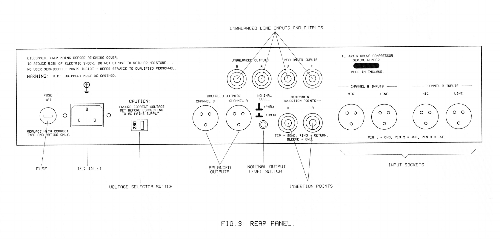
Before connecting the unit to the supply, check that the voltage selector switch on the
rear panel is correctly set. The unit may be set for 115V (accepting voltages in the
range 110V to 120V, 60Hz AC), or to 230V (for voltages in the range 220V to 240V,
50Hz AC). The fuse required is 20mm anti-surge, 1AT.
Warning: attempted operation on the wrong voltage setting, or with an
incorrect fuse, will invalidate the warranty.
Audio Inputs.
Each channel has two female, 3 pin XLR connectors, for mic and line sources. Both
are compatible with either balanced or unbalanced signals, when the mating
connectors are appropriately wired:
Balanced inputs:
- Pin 1 = Ground (screen).
- Pin 2 = Signal Phase (“+” or “hot”).
- Pin 3 = Signal Non-Phase (“-” or “cold”).
Unbalanced inputs:
- Pin 1 = Ground (screen)
- Pin 2 = Signal Phase (“+” or “hot”).
- Pin 3 = Signal Ground
Page 8

When using unbalanced signals, the signal ground may be obtained by linking pins 1
and 3 in the mating XLR connector. Good quality screened cable should be used,
particularly for microphone or low level sources, to prevent hum or noise pickup.
Unbalanced Line Inputs.
An unbalanced line level input is provided for each channel, on a 0.25” mono jack
socket. The mating plugs should be wired as follows:
- Tip = Signal Phase (“+” or “hot”).
- Screen = Ground.
Auxiliary Inputs.
A 2 pin (mono) jack plug is required, which should be wired as follows:
- Tip = Signal Phase (“+” or “hot”).
- Screen = Ground.
Insertion Points.
The insertion points are interfaced via a 3 pin, 0.25” switched jack socket on the rear
of the unit. The pin connections are:
- Sleeve = Ground,
- Tip = Send,
- Ring = Return.
The insertion point is unbalanced, and operates at a nominal level of -2dBu . If used
as an additional send only (e.g. as a send to a tape machine or monitor mixing desk),
the Tip and Ring should be wired together, to preserve the signal path through the
insertion point.
Outputs.
The outputs are via balanced, 3 pin male XLR connectors. The mating connectors
should be wired as follows:
- Pin 1 = Ground (screen),
Page 9

- Pin 2 = Signal Phase (“+” or “hot”),
- Pin 3 = Signal Non-Phase (“-” or “cold”).
If an unbalanced output is required, pins 1 and 3 should both be connected to ground.
Nominal Output Level.
A switch on the rear panel allows the output to be matched to equipment at a nominal
operating level of +4dBu or -10dBu. Most professional equipment requires +4dBu
(approximately 1.2V rms), but some small mixing consoles, portable tape recorders
or domestic audio equipment require -10dBu (approximately 225mV rms). The
switch should be set to the position which results in the best signal to noise ratio,
whilst preserving sufficient headroom.
Unbalanced Outputs.
An unbalanced line output is provided for each channel, on a 0.25” mono jack socket.
- Tip = Signal Phase (“+” or “hot”).
- Screen = Ground.
Ventilation.
The unit generates a small amount of heat internally. This heat should be allowed to
dissipate by convection through the grill in the front panel, which must not be
obstructed. Do not locate the unit where it will be subject to external heating, for
example in the hot air flow from a power amplifier, or on a radiator.
The compressor may be free standing, or mounted in a standard 19” rack.
Rear Panel.
The rear panel connectors are identified in fig.3.
Page 10

OPERATION.
Front Panel.
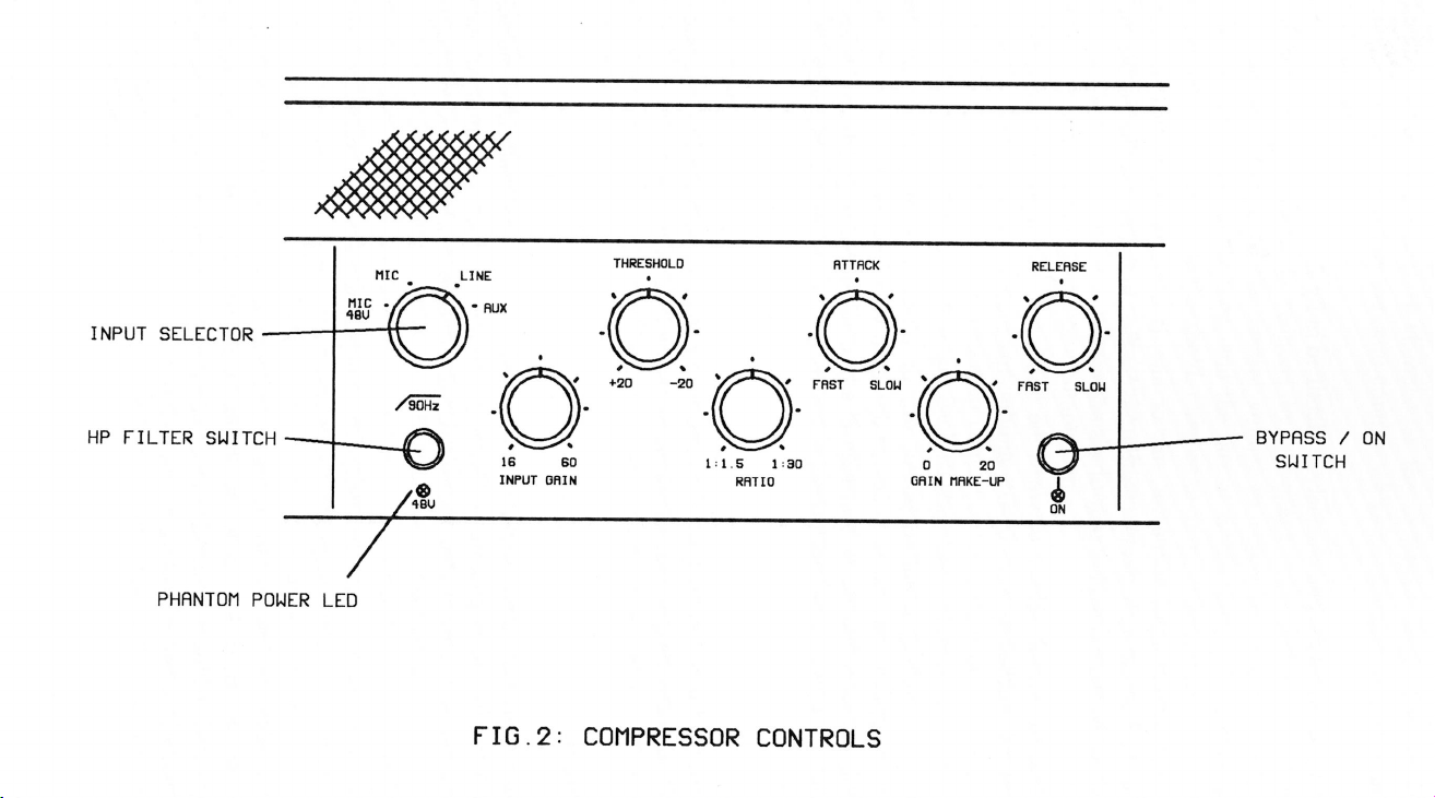
The front panel controls for one channel are identified in fig.2.
Input Stage.
Ensure that the correct input connector, mic or line, is being used and that the front
panel switch is set to the appropriate position. Note that both mic and line inputs may
be connected at the same time, but only one is selected.
The input selector switch selects between the line input, mic input, mic with +48V
phantom power (signalled by a red LED), and the Aux input.
CAUTION: Switching phantom power on, or plugging a microphone in with
phantom power applied, may cause a click or thump in your loudspeakers. To prevent
this happening, ensure that the system gain is set to minimum (e.g. on your mixing
console fader or power amplifier), before operating the switch or plugging in a
microphone.
If the gain required is not known, set the control to minimum with the EQ by-passed,
and gradually increase the gain until the required output level is achieved.
Auxiliary Input.
The front panel auxiliary input sockets may be switched between high level signals
(“Keyboard”) and low level pick-ups (“Guitar”), and are provided with an input gain
control. Note that the channel gain controls remains operative when the Aux input is
selected.
The two aux input sockets may be used, for example, for a stereo keyboard. The
compressors may be operated independently, or linked for true stereo operation.
Aux A input is also normalled to the B input, so both channels may be driven from a
mono input (guitar, etc). With different channel gain settings, one channel may be
lightly compressed, whilst a higher degree of compression is applied to the high gain
channel, resulting in stereo effects from a mono input.
Page 11

Compressor Operation.
A compressor functions by reducing the gain of the signal when it exceeds a certain
level, or threshold. The amount of gain reduction may be fairly gentle through to
limiting, where the signal is clamped at the threshold level. The amount of gain
reduction is determined by the ratio control, which is calibrated as a ratio of the
output to input signals.
The gain of the signal is reduced by a voltage-controlled circuit. Variable time
constants are applied to the control voltage to adjust the rate at which the gain is
reduced, called the attack time, and the rate at which unity gain is restored after the
signal returns to below the threshold, referred to as the release time.
The effect of compression is to limit the dynamic range of a signal. It may be used to
keep a variable output from a bass guitar, for example, at an even level, or to add
punch to vocals, drums, guitar or a complete mix.
Whist the subjective sound quality can be improved by compression, the overall signal
level may be reduced. A gain make-up control at the output of the compressor stage
allows the signal level to be brought back to the same loudness as the uncompressed
signal.
Frequency selective compression may be obtained by inserting an equaliser into the
sidechain signal, from which the control voltage is generated.
Threshold.
The TL Audio compressor has a variable threshold, set by a rotary control calibrated
from +20dBu to -20dBu, resulting in increased compression as the control is rotated
clockwise.
Attack and Release.
The attack time is variable from 0.5msec to 50msec. At 0.5msec attack, the
compressor is fast enough to reduce the gain of a 1KHz signal in less than half a cycle,
effectively preventing an overload of any following equipment which has limited
headroom, such as a digital processor, tape machine or transmitter.
The release time is variable from 40msec to approximately 4 seconds. Adjustment of
the attack and release times allows unobtrusive compression to be applied to virtually
any audio signal, but should very short transients occur the time constants become
signal dependant, generally reduced, to prevent a slow release leaving a “hole” in the
signal after the transient. Also, a fast release setting will be extended by a slow attack
setting. Due to this automatic modification of the time constants, the controls are
simply calibrated “fast” to “slow”.
Page 12

Ratio.
The ratio may be varied from 1:1.5 (very gentle compression) to 1:30 (near limiting).
The compressor normally operates with a “soft-knee”, i.e. the compression is
gradually introduced as the signal passes the threshold, in which case the ratio refers
to the compression eventually obtained.
Gain Make-Up.
Up to 20dB of gain make-up may be applied, to retain the subjective loudness of the
signal.
Stereo Operation.
In normal 2 channel operation, the controls operate independently for each channel.
The compressor may also be set for full stereo operation, where the Threshold, Attack,
Release and Ratio controls for channel A control both channels. The input gain and
gain make-up controls remain separate to allow relative input/output gain balance
adjustment.
In stereo mode, the control voltages are also linked, ensuring that the same amount of
gain reduction is applied to both channels (even if one signal is below the threshold).
This ensures that the stereo image is preserved.
VU Meters.
The compressor is equipped with twin, illuminated VU meters. These meters normally
monitor the audio output from the unit, and are calibrated for 0VU = +4dBu. The
reference point may be internally adjusted by your dealer if required.
The meters may be switched to indicate the amount of compression occurring. If the
signal is below the threshold, the meters will indicate 0dB: i.e. no gain reduction. As
the signal passes through the threshold, the meter will indicate the gain reduction
occurring at the compressor stage. Note that the gain reduction indicated is a measure
of the degree of compression, and does include any gain make-up applied.
Page 13

SPECIFICATIONS
Mic Input: Electronically balanced, input impedance greater than
10Kohm, to suit 150-600 ohm microphones.
48V phantom power available, indicated by red LED.
Gain range +16 to +60dB.
Noise (EIN): -126Bu at maximum gain with a 150 ohm
termination, measured 22Hz-22KHz unweighted.
Maximum input level +10dBu.
3 pin female XLR connector.
Line Input: Electronically balanced, unbalanced compatible, with input
impedance greater than 5Kohm.
Gain range -10dB to +35dB, suitable for nominal input levels
from -20dBu to +20dBu.
Maximum input level +30dBu.
3 pin female XLR connector.
Unbalanced Input:
Input impedance greater than 5Kohm.
Gain range -10dB to +35dB, suitable for nominal input levels
from -20dBu to +20dBu.
Maximum input level +24dBu.
2 pole 0.25” jack socket.
High Pass Filter:
Second order (-12dB per octave),
-3dB at 90Hz.
Auxiliary Input:
Mono or Stereo input,
Switchable for high level (Keyboard) or low level (Guitar) inputs.
Maximum input level +10dBu.
2 pole 0.25” jack socket.
Page 14

Compressor:
Threshold -20dBu to +20dBu,
Attack 0.5msec to 50msec,
Release 40msec to 4 seconds,
Ratio 1:1.5 to 1:30,
Gain Make-Up 0 to +20dB.
Stereo Operation:
Ganged Threshold, Attack, Release and Ratio controls,
Linked control voltages.
VU Meters:
Switchable to output level or compression,
0VU = +4dBu.
Outputs: Electronically balanced, unbalanced compatible.
Rear panel selectable for +4dBu or -10dBu nominal level.
Output impedance less than 10 ohms.
Maximum level +26dBu into 10Kohms, +22dBu into 600
ohms (+4dBu nominal, balanced).
3 pin male XLR connector.
Unbalanced Outputs:
Output impedance 47 ohms.
Maximum level +20dBu into 10Kohms.
2 pole 0.25” jack socket.
Frequency Response:
10Hz to 40KHz, +0, -1dB.
Noise: Noise floor -85dBu with line input at 0dB gain and compressor
by-passed, -80dBu with compressor active (+4dBu nominal level).
-95dBu and -90dBu respectively at -10dBu nominal level.
Page 15

Dynamic Range:
106dB.
Distortion:
THD+N: 0.05%, 10Hz-40KHz.
IMD: 0.03%.
(Line input at 0dBu and 0dB gain with compressor in, after 10 minute warm up time).
Sidechain Insertion Points:
Unbalanced, switched 3 pin jack socket, tip = send,
ring = return.
Nominal level -2dBu.
Output impedance 47 ohms.
Return input impedance 10Kohms.
Power Requirements:
Rear panel selectable for 220-240V 50Hz or 110-120V 60Hz
operation.
Rear panel fuse 20mm, 1AT.
Power consumption 30VA typical.
Detachable 3 pin IEC connector, mating connector and cable
supplied.
Front panel On/Off switch with green LED.
Dimensions:
19” rack mounting, 2U high.
483mm wide x 88mm high x 205mm deep.
Weight: 6Kg.
In line with a policy of continuous development, the above specifications are subject to change without
notice.
Page 16

SERVICE
Should the compressor require service, it must be taken or posted to an authorised
dealer. Please retain the original packing for possible future use, and ensure the unit is
suitably protected during transit. The manufacturer cannot accept responsibility for
damage caused during transportation.
The compressor is protected by a limited warranty for a period of one year from the
date of purchase. During this period, any faults due to defective materials or
workmanship will be repaired free of charge. The warranty excludes damage caused
by deliberate or accidental misuse, operation on the incorrect mains voltage, or
without the correct type and value of fuse fitted. It is the user’s responsibility to ensure
fitness for purpose in any particular application. The warranty is limited to the original
purchase price of the equipment, and excludes any consequential damage or loss.
Please retain proof of purchase, and record the following details:
Serial Number.............................
Date purchased...........................
Dealer.........................................
 Loading...