

Page 1
BC820v2
IP Box camera with Day/Night
Installation Manual
Page 2

Note: To ensure proper operation, please read this manual thoroughly before using the
product and retain the information for future reference.
Copyright © 2017 Siqura B.V.
All rights reserved.
BC820v2
Installation Manual v1 (173101-1)
AIT55
Nothing from this publication may be copied, translated, reproduced, and/or published by
means of printing, photocopying, or by any other means without the prior written permission
of Siqura.
Siqura reserves the right to modify specifications stated in this manual.
Brand names
Any brand names mentioned in this manual are registered trademarks of their respective
owners.
Liability
Siqura accepts no liability for claims from third parties arising from improper use other than
that stated in this manual.
Although considerable care has been taken to ensure a correct and suitably comprehensive
description of all relevant product components, this manual may nonetheless contain errors
and inaccuracies. We invite you to offer your suggestions and comments by email via
[email protected]. Your feedback will help us to further improve our documentation.
How to contact us
If you have any comments or queries concerning any aspect related to the product, do not
hesitate to contact:
Siqura B.V.
Zuidelijk Halfrond 4
2801 DD Gouda
The Netherlands
General : +31 182 592 333
Fax : +31 182 592 123
E-mail : [email protected]
WWW : http://www.tkhsecurity.com
2
Page 3

Contents
1 About this manual ..................................................................................... 4
2 Safety and compliance .............................................................................. 5
2.1 Safety ................................................................................................ 5
2.2 Protection against overvoltage ............................................................... 7
2.3 Cautions ............................................................................................. 8
2.4 Compliance ......................................................................................... 9
3 Product overview ...................................................................................... 10
3.1 Models ............................................................................................... 10
3.2 Description ......................................................................................... 11
3.3 Package contents ................................................................................. 12
3.4 Dimensions ......................................................................................... 12
4 Install the camera ..................................................................................... 13
4.1 Mount the lens .................................................................................... 13
4.2 Mount the camera ................................................................................ 13
5 Connect the camera .................................................................................. 15
5.1 Back panel .......................................................................................... 15
5.2 Light sensor ........................................................................................ 16
5.3 Power the camera ................................................................................ 17
5.4 Connect to network .............................................................................. 17
5.5 Connect audio ..................................................................................... 18
5.6 Connect alarm I/O ............................................................................... 18
5.7 Connect data ...................................................................................... 19
5.8 microSD Card ...................................................................................... 19
6 Access the camera .................................................................................... 20
6.1 System requirements ........................................................................... 20
6.2 Connect via web browser ...................................................................... 21
6.3 Find the unit with Device Manager ......................................................... 21
6.4 Change network settings with Device Manager ......................................... 22
6.5 Log on to the unit ................................................................................ 23
6.6 Install Viewer ...................................................................................... 24
6.7 Focus adjustment ................................................................................ 25
6.8 System compatibility ............................................................................ 25
Appendix: Enable UPnP in Windows 7 ....................................................... 26
Appendix: Delete Viewer ........................................................................... 27
Appendix: Set up Internet security ........................................................... 28
Index ...................................................................................................... 29
3
Page 4

1 About this manual
What's in this manual
This manual gives you the information you need to install the BC820v2 camera. It tells:
● How to mount the camera
● How to mount the lens
● How to connect the camera
● How to power the camera
Who this manual is for
These instructions are for all professionals who will install the BC820v2.
What you need to know
You will have a better understanding of how the BC820v2 works if you are familiar with:
● Camera technologies
● CCTV systems and components
● Hazardous environments and ATEX/IECEx regulations (EX models)
● Ethernet network technologies and Internet Protocol (IP)
● Windows environments
● Video, audio, and contact closure transmissions
● Video compression methods
Before you continue
Before you continue, read and obey all instructions and warnings in this manual. Keep this
manual with the original bill of sale for future reference and, if necessary, warranty service.
When you unpack your product, make sure there are no missing or damaged items. If any
item is missing, or if you find damage, do not install or operate this product. Ask your supplier
for assistance.
Why specifications may change
At TKH Security, we are committed to delivering high-quality products and services. The
information given in this manual was current when published. As we continuously seek to
improve our products and user experience, all features and specifications are subject to
change without notice.
We like to hear from you!
Customer satisfaction is our first priority. We welcome and value your opinion about our
products and services. Should you detect errors or inaccuracies in this manual, we would be
grateful if you would inform us. We invite you to offer your suggestions and comments via
[email protected]. Your feedback helps us to further improve our documentation.
4
Page 5

2 Safety and compliance
This chapter gives the BC820v2 safety instructions and compliance information.
In This Chapter
2.1 Safety................................................................................................................... 5
2.2 Protection against overvoltage..................................................................................7
2.3 Cautions................................................................................................................8
2.4 Compliance............................................................................................................9
2.1 Safety
The safety information contained in this section, and on other pages of this manual, must be
observed whenever this unit is operated, serviced, or repaired. Failure to comply with any
precaution, warning, or instruction noted in the manual is in violation of the standards of
design, manufacture, and intended use of the module. TKH Security assumes no liability for
the customer's failure to comply with any of these safety requirements.
Trained personnel
Installation, adjustment, maintenance, and repair of this equipment are to be performed by
trained personnel aware of the hazards involved. For correct and safe use of the equipment
and in order to keep the equipment in a safe condition, it is essential that both operating and
servicing personnel follow standard safety procedures in addition to the safety precautions
and warnings specified in this manual, and that this unit be installed in locations accessible to
trained service personnel only.
Safety requirements
The equipment described in this manual has been designed and tested according to the
UL/IEC/EN 60950-1 safety requirements. For compliance information, see the EU
Declaration of Conformity, which is available for download at www.tkhsecurity.com/supportfiles.
Warning: If there is any doubt regarding the safety of the equipment, do not put it into
operation.
This might be the case when the equipment shows physical damage or is stressed beyond
tolerable limits (for example, during storage and transportation).
Important: Before opening the equipment, disconnect it from all power sources.
The equipment must be powered by a SELV1 power supply. This is equivalent to a Limited
Power source (LPS, see UL/IEC/EN 60950-1 clause 2.5) or a "NEC Class 2" power supply.
When this module is operated in extremely elevated temperature conditions, it is possible for
internal and external metal surfaces to become extremely hot.
1. SELV: conforming to IEC 60950-1, <60 Vdc output, output voltage galvanically isolated
from mains. All power supplies or power supply cabinets available from TKH Security comply
with these SELV requirements.
5
Page 6

Safety and compliance
Optical safety
The following optical safety information applies to BC820v2 models with SFP interface.
This product complies with 21 CFR 1040.10 and 1040.11 except for deviations pursuant to
Laser Notice No. 50, dated June 24, 2007. This optical equipment contains Class 1M lasers or
LEDs and has been designed and tested to meet IEC 60825-1:1993+A1+A2 and IEC
60825-2:2004 safety class 1M requirements.
Warning: Optical equipment presents potential hazards to testing and servicing personnel,
owing to high levels of optical radiation.
When using magnifying optical instruments, avoid looking directly into the output of an
operating transmitter or into the end of a fiber connected to an operating transmitter, or there
will be a risk of permanent eye damage. Precautions should be taken to prevent exposure to
optical radiation when the unit is removed from its enclosure or when the fiber is disconnected
from the unit. The optical radiation is invisible to the eye.
Use of controls or adjustments or procedures other than those specified herein may result in
hazardous radiation exposure.
The installer is responsible for ensuring that the label depicted below (background: yellow;
border and text: black) is present in the restricted locations where this equipment is installed.
EMC
This device has been tested and found to meet the CE regulations relating to EMC and
complies with Part 15 of the FCC rules. Operation is subject to the following two conditions:
(1) This device may not cause harmful interference, and (2) This device must accept any
interference received, including interference that may cause undesired operation. These limits
are designed to provide reasonable protection against interference to radio communications in
any installation. The equipment generates, uses, and can radiate radio frequency energy;
improper use or special circumstances may cause interference to other equipment or a
performance decrease due to interference radiated by other equipment. In such cases, the
user will have to take appropriate measures to reduce such interactions between this and
other equipment.
Any interruption of the shielding inside or outside the equipment could make the equipment
more prone to fail EMC requirements.
Non-video signal lines must use appropriate shielded Cat 5 cabling (S-FTP), or at least an
equivalent. Ensure that all electrically connected components are carefully earthed and
protected against surges (high voltage transients caused by switching or lightning).
ESD
Electrostatic discharge (ESD) can damage or destroy electronic components. Proper
precautions should be taken against ESD when opening the equipment.
6
Page 7

Safety and compliance
RoHS
Product disposal
Global concerns over the health and environmental risks associated with the
use of certain environmentally-sensitive materials in electronic products have
led the European Union (EU) to enact the Directive on the Restriction of the
use of certain Hazardous Substances (RoHS) (2011/65/EU). TKH Security
offers products that comply with the EU’s RoHS Directive.
The unit contains valuable materials which qualify for recycling. In the
interest of protecting the natural environment, properly recycling the unit at
the end of its service life is imperative.
When processing the printed circuit board, dismantling the lithium battery
calls for special attention. This kind of battery, a button cell type, contains so
little lithium, that it will never be classified as reactive hazardous waste. It is
safe for normal disposal, as required for batteries by your local authority.
2.2 Protection against overvoltage
Note: The following instructions must be observed for outdoor installations.
The installer is responsible for protection of the camera against overvoltage.
These international standards apply (equivalent standards may also be used):
● IEC 60364-4-44 Electrical installations of buildings - Part 4-443:
Protection against overvoltages of atmospheric origin or due to switching.
● IEC 60364-5-53 Electrical installations of buildings - Part 5-534:
Devices for protection against overvoltages
● IEC 62305 Protection against lightning – All parts
The information below can be used to determine the required measures.
Transient overvoltage immunity test level
The equipment installed in this outdoor enclosure, including camera and power supply, is
tested for application in an industrial environment. The transient overvoltage immunity is
tested according IEC 61000-6-2 and IEC 61000-4-5 for industrial levels.
● For AC power ports the test level is 2kV Line to Earth and 1kV Line to Line.
● For signal ports the test level is 1kV Line to Earth. (no Line to Line test required)
Overvoltage Category according IEC 60950-22
Mains-operated outdoor equipment shall be suitable for the highest Overvoltage Category
expected in the installation location. The Overvoltage Category for outdoor equipment can be
higher than for indoor equipment. This outdoor enclosure and the internal camera equipment
is designed for overvoltage category II.
The installer is required to provide additional protection to reduce the overvoltage if the
equipment is subject to transient overvoltages exceeding those for Overvoltage Category II.
7
Page 8

Safety and compliance
It is permitted to include protection components within the outdoor equipment. Components
used to reduce the Overvoltage Category, Surge Protection Devices (SPD), shall comply with
the requirements of IEC 61643-series or equivalent standards.
NOTE: The Overvoltage Category of outdoor equipment is normally considered to be one of
the following:
● if powered via the normal building installation wiring, Overvoltage Category II;
● if powered directly from the mains distribution system, Overvoltage Category III;
● if at, or in the proximity of, the origin of the electrical installation, Overvoltage Category
Protection against lightning strikes (direct and indirect)
Additional protection is also required for protection against direct or indirect lightning strikes
according the IEC 62305 series standards, or equivalent standards.
Consideration shall be given to the following:
● The use of properly earthed air-termination rods for pole-mounted or high-mounted
● Avoid wiring loops
● Locate protection devices close to the protected equipment (within 0.5 m)
● Keep wiring to protection devices short.
IV.
cameras
2.3 Cautions
Handle the camera carefully
Do not abuse the camera. Avoid bumping and shaking. The camera can be damaged by
improper handling or storage.
Do not disassemble the camera
To prevent electric shock, do not remove screws or covers. There are no user serviceable
parts inside. Consult technical support if a camera is suspected of malfunctioning.
Do not exceed the ratings given in the Technical Specifications
Make sure that the power source is appropriate before you plug in and operate the unit. Use
the unit under conditions where the temperature remains within the range given in the
Technical Specifications of this product. You can download the BC820v2 datasheet at
www.tkhsecurity.com/support-files.
Do not expose indoor models to moisture
The indoor camera model is designed for indoor use or use in locations where it is protected
from rain and moisture. Turn the power off immediately if the camera is wet and ask a
qualified technician for servicing. Moisture can damage the camera and also create the danger
of electric shock.
Do not use strong or abrasive detergents to clean the camera
Use a dry cloth to clean the camera when it is dirty. If the dirt is hard to remove, use a mild
detergent and wipe gently. To clean the lens, use lens tissue or a cotton tipped applicator and
ethanol. Do not clean the lens with strong detergents.
8
Page 9

Safety and compliance
Never face the camera towards the sun
Do not aim the camera at bright objects. Whether the camera is in use or not, never aim it at
the sun or other extremely bright objects, as this can damage the camera.
2.4 Compliance
The EU Declaration of Conformity for this product is available for download at
www.tkhsecurity.com/support-files.
9
Page 10
3 Product overview
This chapter introduces the BC820v2 models and their features.
In This Chapter
3.1 Models.................................................................................................................10
3.2 Description...........................................................................................................11
3.3 Package contents..................................................................................................12
3.4 Dimensions.......................................................................................................... 12
3.1 Models
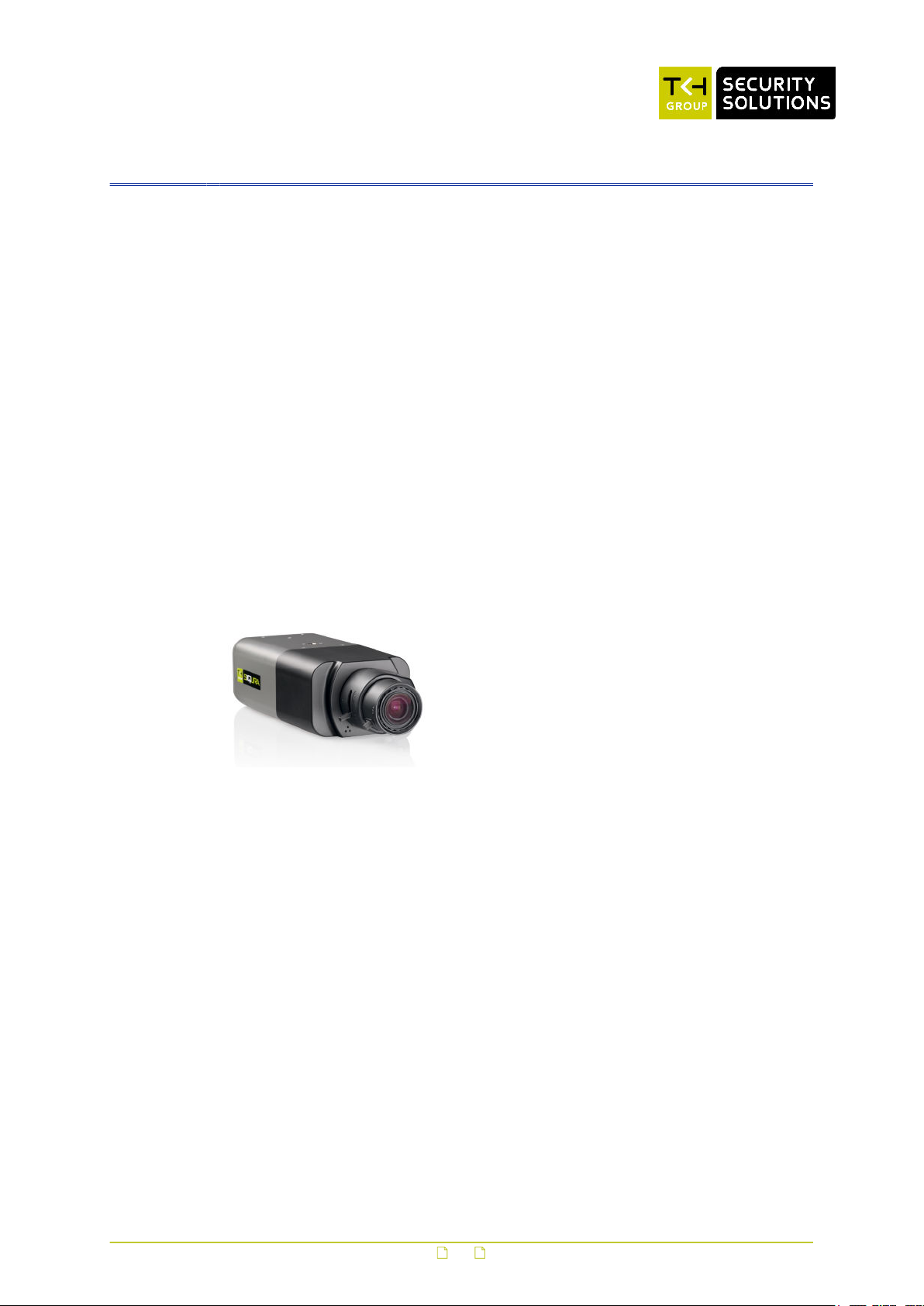
The BC820v2 is available as:
● a standard box style camera with RJ-45 network connector
● a standard box style camera with SFP interface
BC820v2 HD IP box camera with H.264 and Day/Night
● 1/2.7" Progressive scan CMOS imager
● Multiple resolutions: 1080p/720p
● H.264 and MJPEG compression
● Two-way audio
● Day/Night with IR cut filter
● 24 Vac / 12 Vdc / 24 Vdc / 802.3af PoE
● microSD support
Note: Lens sold separately
● ONVIF Profile S compliant
● Programming Interface (HTTP API) support
● Alarm I/O (1 output, 1 input)
● HTTPS, 802.1x, IPv6, QoS
● IP Address filter
● SNMP v1/v2/v3
● Tampering alarm
● Video Motion Detection
● Wide Dynamic Range, Backlight Compensation
● Privacy masks
● Analogue output
10
Page 11
Product overview
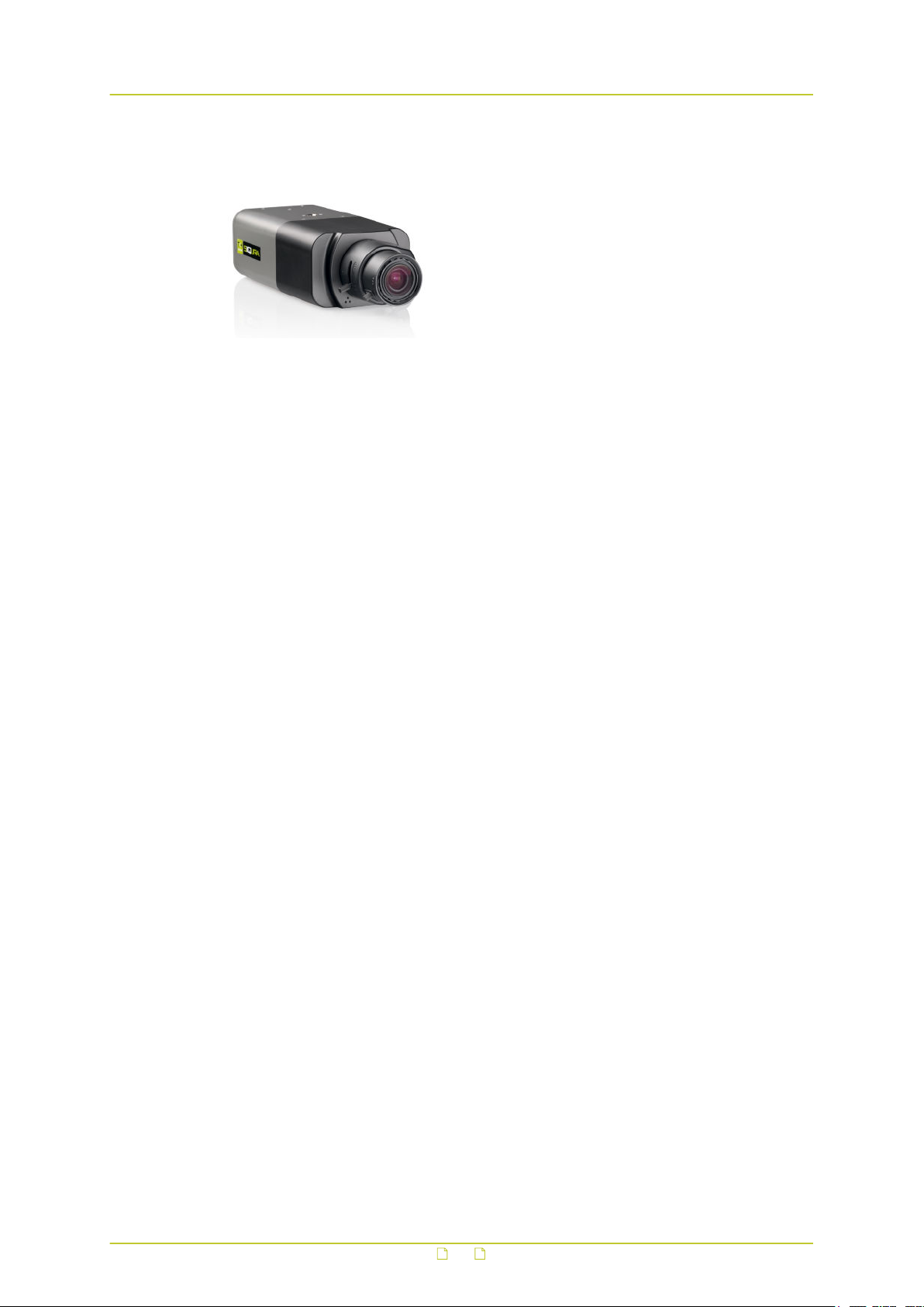
BC820v2-SFP HD IP box camera with H.264, Day/Night and SFP
Note: Lens sold separately
3.2 Description
The BC820v2 is a full-featured fixed IP camera providing high-quality high-definition images.
Multistream high definition
interface
In addition to the features above:
● SFP Interface
BC820v2 cameras have quad-stream capability (triple-stream in WDR 2 shutter mode) for
simultaneous streaming of combinations of H.264 streams with one MJPEG stream. The
MJPEG stream can be allocated to any configured resolution format (limited to 1080p).
Multiple combinations of resolution and frame rate can be configured to satisfy different live
viewing and recording scenarios. Full frame rate, full-HD 1080p streaming with a D1 second
stream or dual 720p streaming is possible.
Open standards
Multiple options are available to easily integrate the BC820v2 to a video management system.
In support of open standards, these cameras are compliant with the ONVIF Profile S
specification and the Programming Interface (HTTP API). The BC820v2 seamlessly integrates
with any Pan/Tilt station by offering free configurable commands issued to the PT station
through the serial data interface.
Day/Night
The BC820v2 provides automatic day/night functionality with configurable thresholds, for use
in low-light situations. Under poor lighting conditions, the camera automatically becomes
infrared-sensitive by removing the IR-cut filter. This ensures that even in minimal light the
camera still produces clear images.
Backlight compensation
Backlight compensation enhances image visibility in difficult lighting conditions. In situations
where the observed object is unclear due to being underlit or overlit (such as in a hallway
entrance with many windows), backlight compensation improves image exposure by using the
light near the object as a reference.
Wide dynamic range
The BC820v2 provides two modes for wide dynamic range. The first mode uses different gain
ratios for differently illumined areas to bring details in the darker areas of an image without
saturation in the brighter parts. The second mode uses a two-shutter mechanism which
applies two different exposure settings to capture both darker and lighter areas with excellent
details. The resulting image is the optimal aggregation of both exposures.
11
Page 12
Product overview
Privacy masks
With privacy masks you can cover parts of the image. By concealing areas with sensitive or
personal information you can prevent these from appearing on a monitor or in recorded video.
Power source choices
The BC820v2 can be powered by 12 Vdc, 24 Vdc, 24 Vac, or over the network with 802.3afcompliant PoE sources.
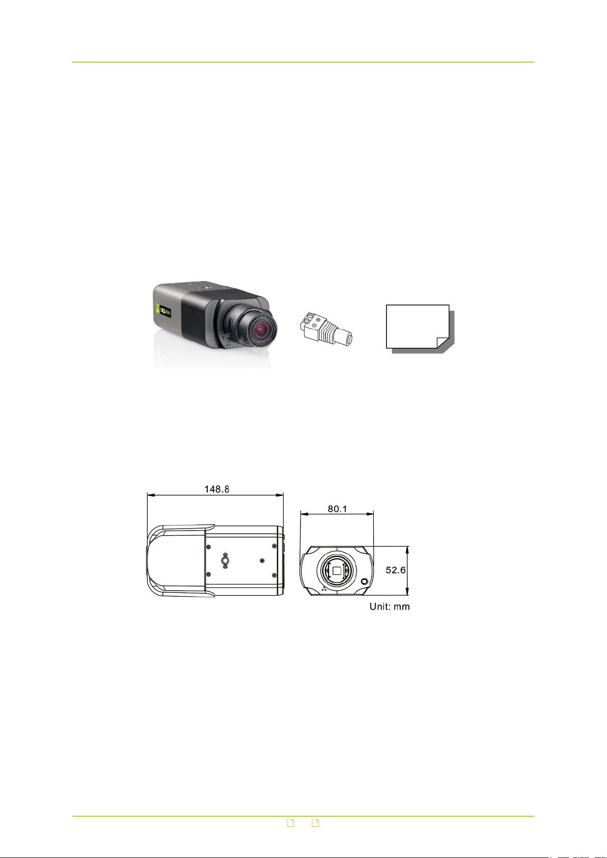
3.3 Package contents
Note: Lens sold separately
BC820v2H3/BC820v2H3-SFP Power connector Quick Start Guide
3.4 Dimensions
12
Page 13
4 Install the camera
In This Chapter
4.1 Mount the lens......................................................................................................13
4.2 Mount the camera.................................................................................................13
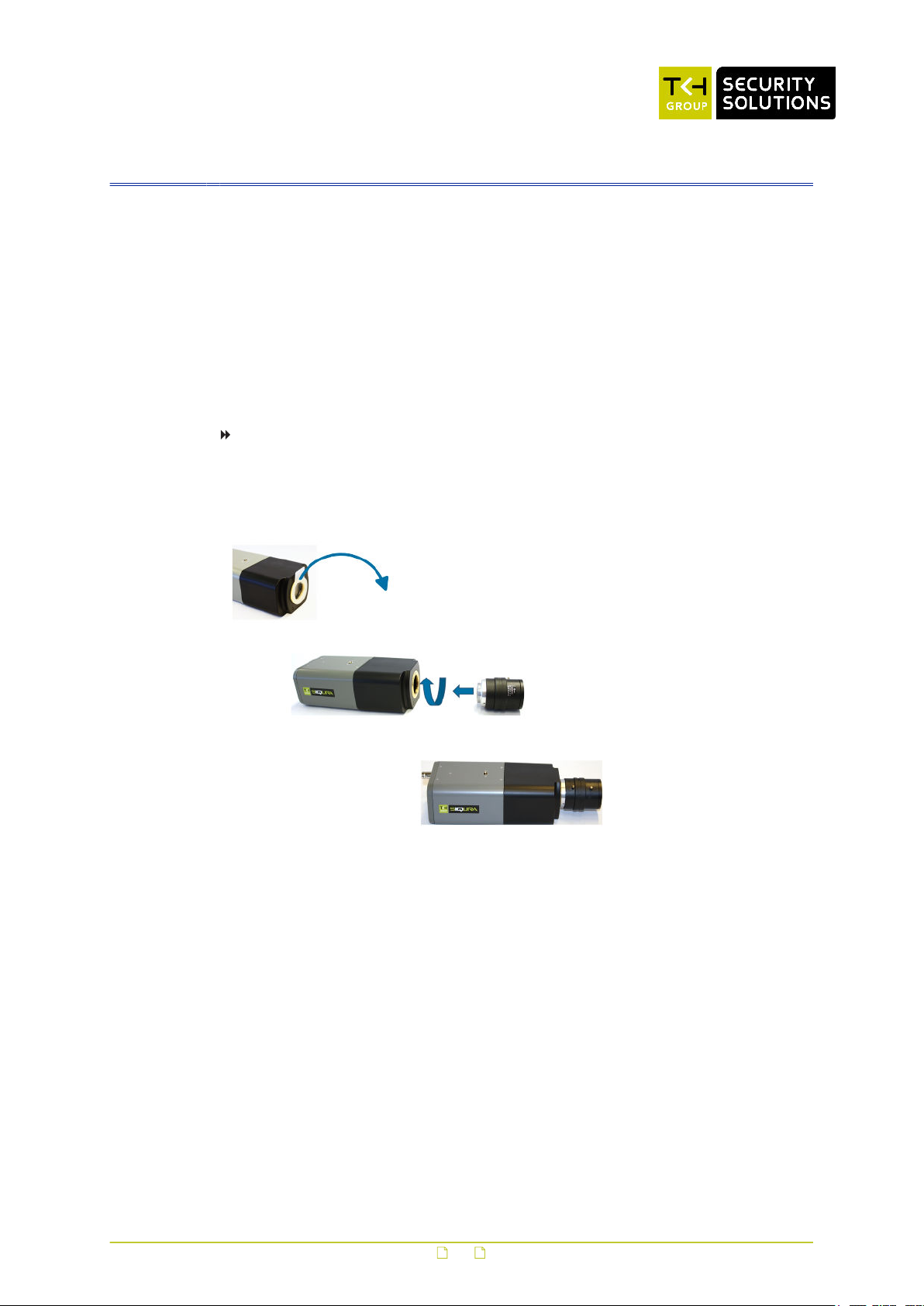
4.1 Mount the lens
Lenses for the BC820v2 camera series are sold separately.
To mount a lens onto the camera
1 Remove the sensor cover from the camera.
2 Attach the lens to the camera.
Mounting the lens
4.2 Mount the camera
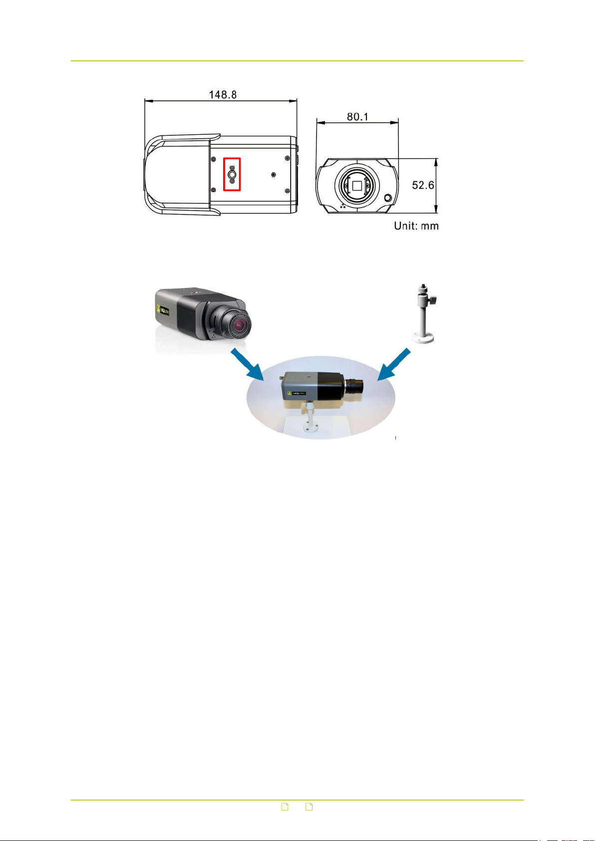
Using the WM04 accessory, the BC820v2 can be installed directly on a wall or ceiling, provided
the surface has sufficient strength to support the camera. The mounting bracket screws
directly into the screw hole shown in the figure below. No tools are required. There are screw
holes on the top and bottom of the camera.
13
Page 14
Install the camera
Screw hole highlighted in red
Mount the camera with WM04 wall mount
14
Page 15
5 Connect the camera
To get the camera up and running, you need to connect it to power and the network. The
connectors are located on the back panel of the camera body. The back panel also has
connectors for audio, data and alarms.
In This Chapter
5.1 Back panel........................................................................................................... 15
5.2 Light sensor......................................................................................................... 16
5.3 Power the camera................................................................................................. 17
5.4 Connect to network............................................................................................... 17
5.5 Connect audio...................................................................................................... 18
5.6 Connect alarm I/O................................................................................................ 18
5.7 Connect data........................................................................................................19
5.8 microSD Card....................................................................................................... 19
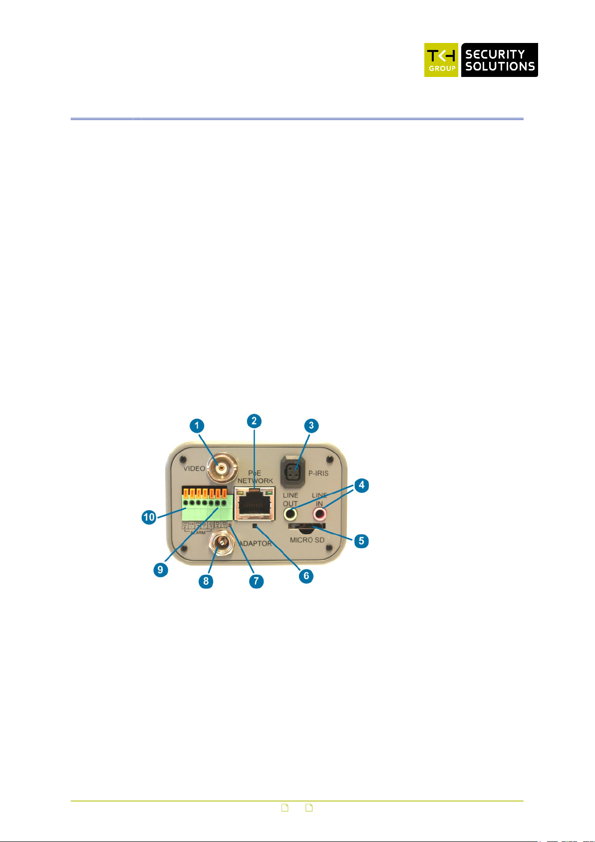
5.1 Back panel
BC820v2 back panel
15
Page 16
Connect the camera
Feature Description
1 Video (BNC connector) For analogue video output.
2 Network connector (RJ-45) and
LEDs
3 P-Iris P-Iris lens connection.
4 Audio I/O Two-way audio transmission.
5 microSD Card slot Insert the microSD card into the card slot to
6 Reset button With the camera powered up, use a proper
7 Power LED For power connection indication (green light).
8 Power (12 Vdc/ 24 Vdc / 24 Vac) For power connection.
9 Data (RS-485) 6. D+
10 Alarm I/O 1. Alarm In 2 +
For network/PoE connection and activity
indication.
store videos and snapshots. Do not remove
the microSD card when the camera is powered
on.
tool to push and hold the reset button for at
least 20 seconds. All settings, including the
camera's IP address, are reset to the original
factory settings.
7. D-
2. Alarm In -
3. Alarm In 1 +
4. Alarm In -
5. Alarm Out +
5.2 Light sensor
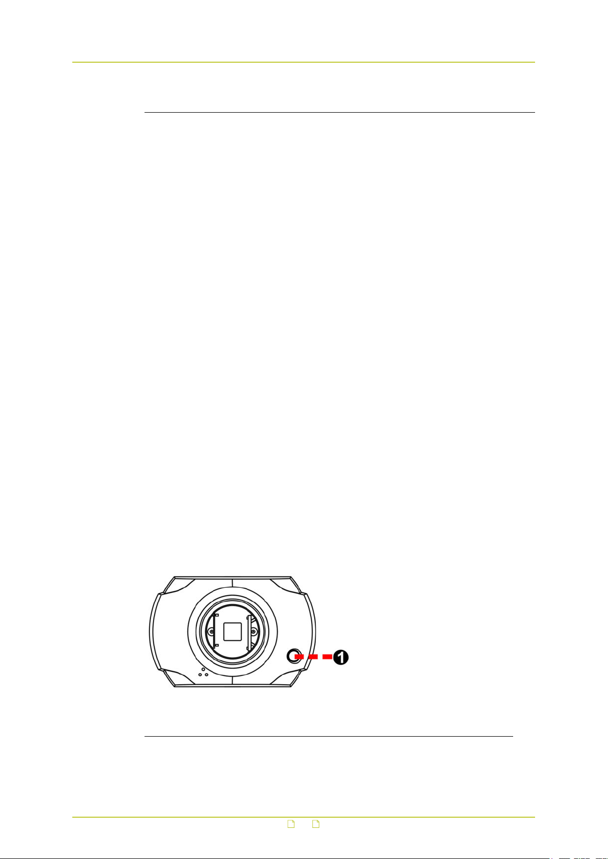
A light sensor is used to detect the ambient light for the Day/Night switching function. The
light sensor is located at the front of the camera. The location and definition of the light
sensor is as given below.
Feature Description
1 Light sensor Ambient light detection for Day/Night switching
function
16
Page 17

Connect the camera
5.3 Power the camera
The BC820v2 supports 24 Vac / 24 Vdc / 12 Vdc via terminal block and Power over Ethernet
(802.3af PoE). The BC820v2 consumes 3.8 W of power.
To power the BC820v2 with DC 12 V / DC 24 V / AC 24 V
1 If necessary, insert the leads from your power source into the supplied power connector,
as indicated by the connector labelling.
2 Insert the power connector plug into the ADAPTOR connector on the back panel.
3 Plug the power supply into a mains outlet.
To power the BC820v2 with Power over Ethernet (PoE)
● Connect the NETWORK RJ-45 connector on the back panel of your BC820v2 to an
appropriate network switch.
Powering with PoE requires that IEEE 802.3AF Power Sourcing Equipment (PSE) is
available on the network.
● Use Cat 5 Ethernet cable up to 100 m in length.
Connect to a hub or switch with straight-through cable.
Use crossover cable to connect directly to a PC.
5.4 Connect to network
Category 5 Ethernet cable is recommended for network connections. For the best transmission
quality, do not exceed a cable length of 100 metres.
To connect through a hub or switch
● Connect one end of a straight through Cat 5 cable to the RJ-45 connector of the All-in-One
cable and the other end of the cable to the network switch.
To connect directly to a PC
● Connect one end of a crossover Cat 5 cable to the RJ-45 connector of the All-in-One cable
and the other end of the cable to the PC.
Refer to the following figure to determine whether you have established an Ethernet
connection.
Ethernet socket LEDs green/yellow
Green on/off : 100/10 Mbit
Yellow on/blink : link OK, active
Yellow off/flash : link down, TX attempt
17
Page 18
Connect the camera
5.5 Connect audio
The BC820v2 can be used to provide a two-way audio channel.
To connect audio
● Connect the audio input and output cables to the LINE IN and LINE OUT connectors on the
back panel of the camera.
For the location of the audio connectors, see section Back panel.
To configure audio settings
1 Log on to the web interface of the camera.
For instructions on how to do this, see section Log on to the camera.
2 On the Streaming menu, click Audio.
3 Select one of the following options:
- Full-duplex (Talk and listen simultaneously)
- Half-duplex (Talk or listen, not at the same time)
- Simplex (Talk only)
- Simplex (Listen only)
- Disable
5.6 Connect alarm I/O
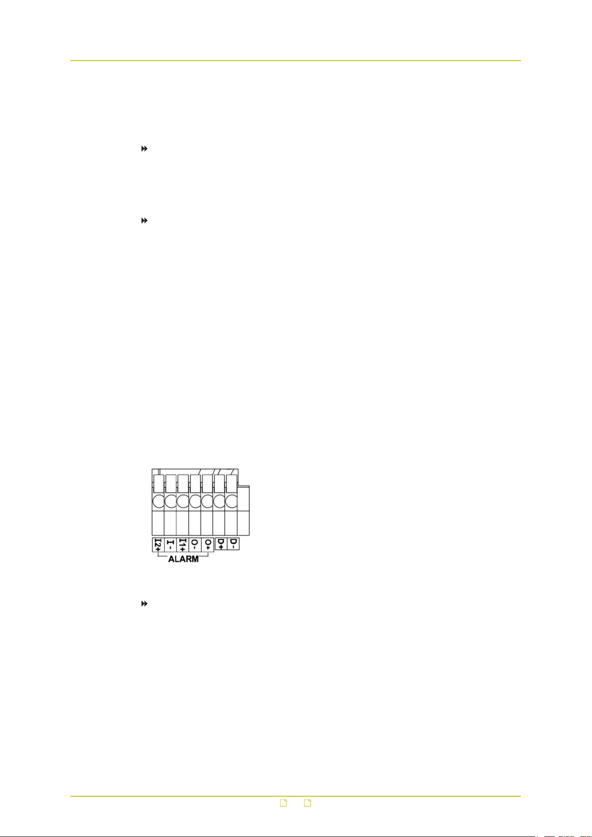
The camera equips one relay input and one relay output for alarm application. Refer to the
alarm pin definitions below to connect alarm devices to the IP camera as necessary.
To configure the alarm settings
1 Log on to the web interface of the camera.
For instructions on how to do this, see section Log on to the camera.
2 In the System menu, go to the Events webpages and configure the alarms as desired.
1. Alarm In 2 +
2. Alarm In −
3. Alarm In 1 +
4. Alarm Out -
5. Alarm Out
18
Page 19
Connect the camera
5.7 Connect data
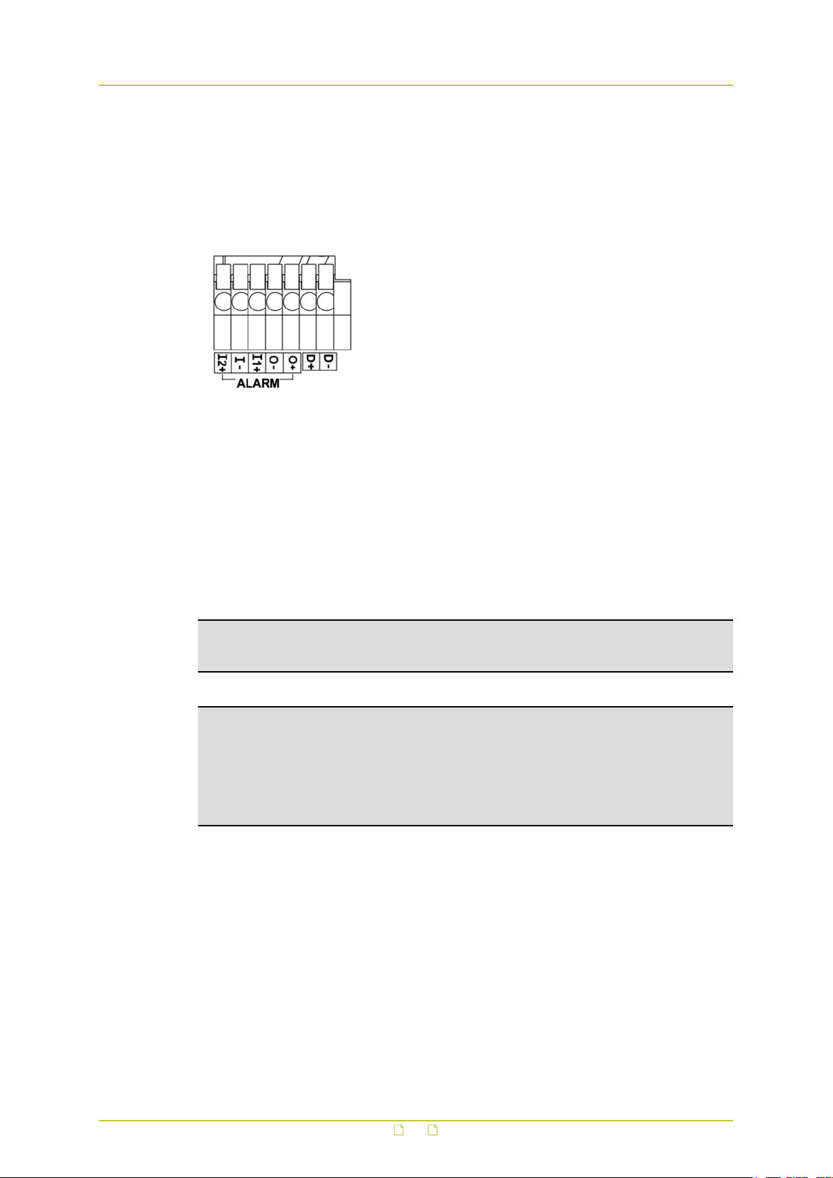
The RS-485 connector is the interface for connecting with the pan and tilt positioning system
of the camera. With RS-485 support, the IP camera is capable of working with a Pan Tilt Head
for pan and tilt control. Before implementing pan/tilt control, make sure that the Pan Tilt Head
is correctly connected to the IP camera’s RS-485 port.
5.8 microSD Card
6. D+
7. D-
BC820v2 cameras support a microSD card (up to 64 GB) for storing event-triggered and
scheduled recordings. For the location of the microSD card slot, see section Back panel.
On the Storage Management page of the web interface, administrators can view capacity
information of the microSD/SDHC card and a recording list with all the recording files that are
saved on the memory card. Administrators can also format the SD card and implement
automatic recording cleanup. For more information, see the User Manual.
Note: Format the microSD/SDHC card when using it for the first time. Formatting is also
required when a memory card already used on one camera is transferred to another camera
with a different software platform.
Important: TKH Security advises to use high-grade, highly-durable SD cards. Note that SD
cards are limited to the number of write cycles ranging from 1000 (off-the-shelf high-grade
card MLC or TLC NAND) to 100.000 (4 GB industrial SLC NAND). Intensive usage will
eventually wear out the card. The number of write cycles times the capacity of the SD card
gives you the total amount of data that can be written to the card in its life time. A 32 GB
microSDHC with 2000 write cycles, for example, can write 64 TB before it should be
replaced.
19
Page 20

6 Access the camera
The webpages of the BC820v2 offer a user-friendly interface for configuring the settings of the
unit and viewing live video images over the network. This chapter explains how to connect to
the built-in web server.
In This Chapter
6.1 System requirements............................................................................................ 20
6.2 Connect via web browser....................................................................................... 21
6.3 Find the unit with Device Manager...........................................................................21
6.4 Change network settings with Device Manager..........................................................22
6.5 Log on to the unit................................................................................................. 23
6.6 Install Viewer....................................................................................................... 24
6.7 Focus adjustment..................................................................................................25
6.8 System compatibility............................................................................................. 25
6.1 System requirements
You can log on to the web interface of your BC820v2 unit from a PC which is on the same
subnet as the unit. The browsing PC must meet the system requirements given in the table
below and the browser must support ActiveX controls. Make sure that your PC has a good
network connection.
Item System requirement
Personal computer Minimum
1. Intel® Core™ i5-2430M @ 2.4 GHz
2. 4 GB RAM
Recommended
1. Intel® Core™ i7-870 @ 2.93 GHz
2. 8 GB RAM
Operating system Windows 7 or higher
Web browser Internet Explorer
Network card 10Base-T (10 Mbps), 100Base-TX (100 Mbps) or 1000Base-T
(1000 Mbps) operation
Viewer ActiveX control plug-in for Microsoft IE
20
Page 21
Access the camera
6.2 Connect via web browser
To connect to the unit via your web browser
1 Open your web browser.
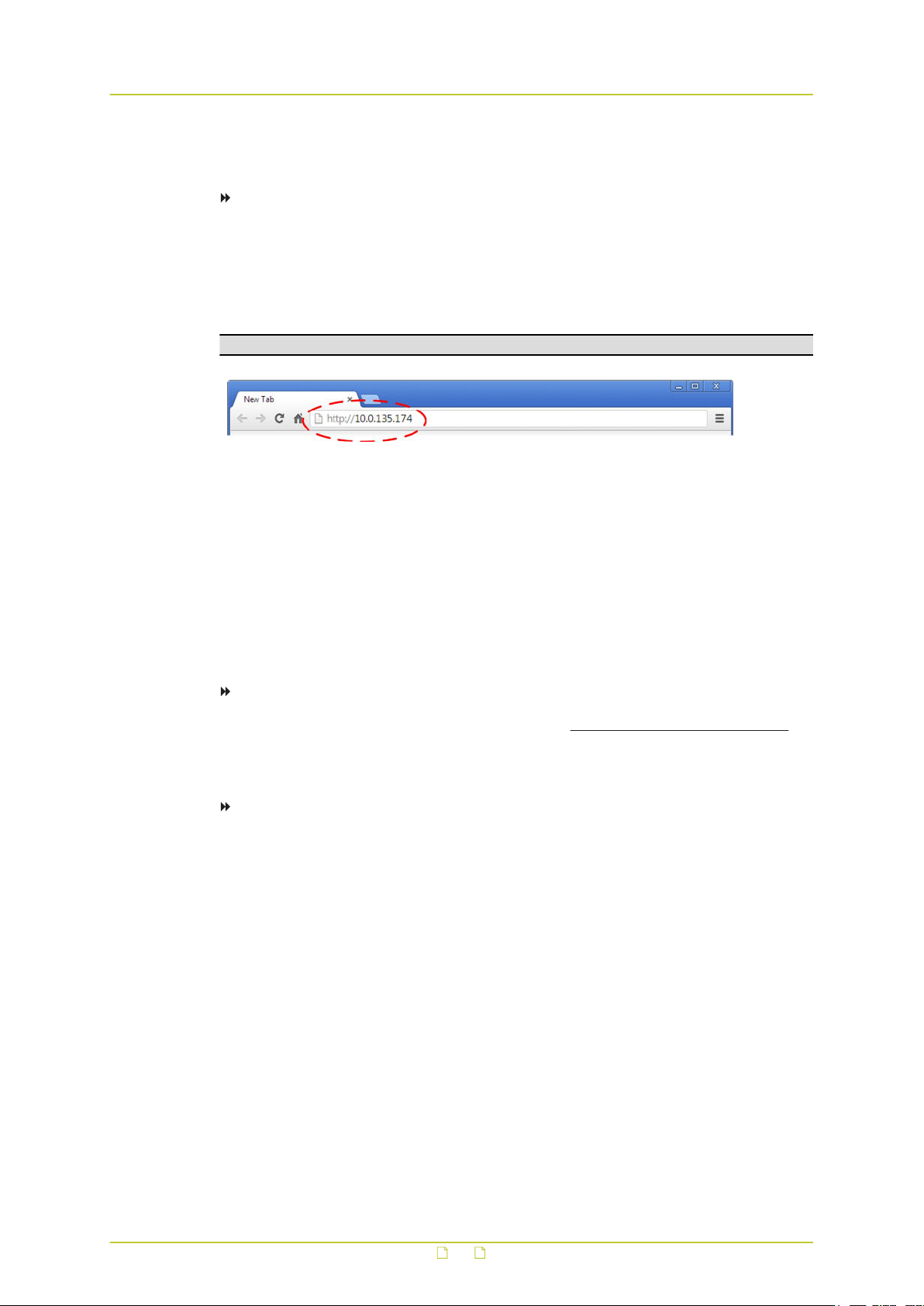
2 Type the IP address of the BC820v2 in the address bar, and then press ENTER.
The factory-set IP address of the BC820v2 is in the 10.x.x.x range. It is printed on a
sticker on the unit.
If your network configuration is correct you are directed to the login page of the unit.
Note: A hard reset sets the IP address of the camera to its factory-default setting.
Type the IP address of the BC820v2 in the address bar of the browser
6.3 Find the unit with Device Manager
Device Manager is a Windows-based software tool that you can use to manage and configure
TKH Security IP cameras and video encoders. The tool automatically locates these devices and
offers you an intuitive interface to set and manage network settings, configure devices, show
device status, and perform firmware upgrade.
To install Device Manager
1 Download the latest version of Device Manager at
2 Double-click the setup file.
3 Follow the installation steps to install the software.
To connect to the unit via Device Manager
1 Start Device Manager
The network is scanned and detected devices appear in the List View pane.
2 If multiple network adapters exist, select the appropriate adapter to scan the network
that you wish to connect to.
3 To refresh the List view pane, click the Rescan now button.
4 Use the tabs in the Tree View pane to define the scope of your search.
5 Click the column headings in the List View pane to sort devices by type, IP address, or
name.
6 Use the Filter box, to search for a specific series or model.
7 To connect to the webpages of the BC820v2, double-click its entry in the device list,
- or -
Right-click the entry, and then click Open Web Page.
The login page of the BC820v2 is opened in your web browser.
www.tkhsecurity.com/support-files.
21
Page 22

Access the camera
Connect to a device via Device Manager
6.4 Change network settings with Device Manager
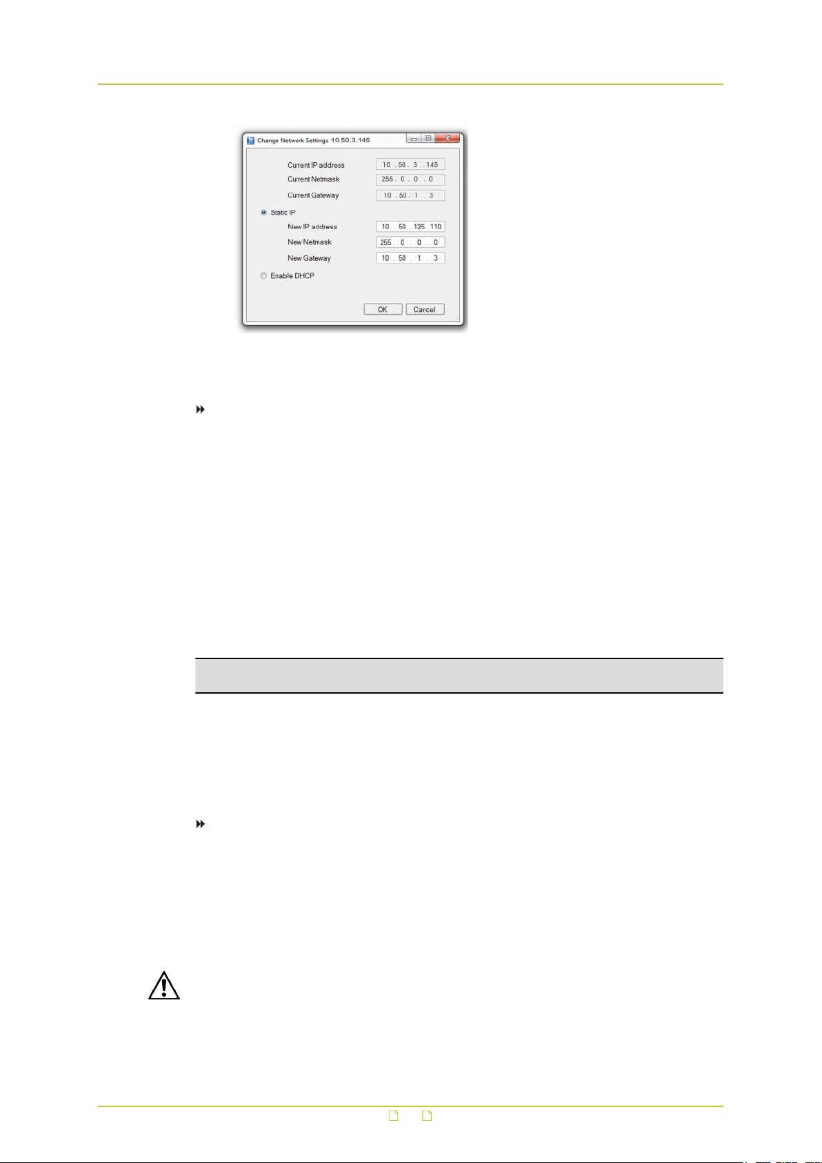
With Device Manager, you can directly change the network settings of the BC820v2.
To assign a static IP address
1 Go to the list of detected devices, and then right-click the entry for the BC820v2.
2 Click Change Network Settings.
3 In Change Network Settings, click Static IP.
4 Provide the camera with an appropriate IP address, netmask, and gateway address for
the desired network configuration, and then click OK.
5 In the pop-up window indicating that you have successfully changed the settings, click
OK.
6 Wait one minute, and then rescan the network.
7 To access the webpages of the BC820v2, double-click its entry in the list of found
devices.
22
Page 23
Access the camera
Assign a static IP address
To assign a DHCP server
1 Record the BC820v2's MAC address (see the Serial no. column in Device Manager) for
future identification
2 In the list of detected devices, right-click the device with the network property that you
would like to change.
3 Click Change Network Settings.
4 In Change Network Settings, click Enable DHCP, and then click OK.
5 In the pop-up window indicating that you have successfully changed the settings, click
OK.
6 Wait one minute, and then rescan the network.
You can identify the device by its MAC address.
7 To access the webpages of the BC820v2, double-click its entry in the list of found
devices.
Note: A DHCP server must be installed on the network in order to provide DHCP network
support.
6.5 Log on to the unit
Users with a valid account for the BC820v2 can log on to the unit.
To log on
1 In the Authentication box, log on with the account that was created for you.
User name and password are case sensitive.
The default user name set at the factory for the BC820v2 is "Admin" with password
"1234".
2 Click Log In.
CAUTION: MAKE SURE THAT YOU CHANGE THE DEFAULT ADMIN PASSWORD AT THE FIRST
LOGIN. TO KEEP THE ACCOUNT SAFE, CREATE A STRONG, COMPLEX PASSWORD. THIS
HELPS TO PREVENT UNAUTHORISED ACCESS FROM PEOPLE WHO TRY TO USE THE DEFAULT
ACCOUNT.
23
Page 24
Access the camera
To create a strong password
● Use at least eight characters
● Do not include your real name, user name, company name, or other personal information
● Do not use complete words that can be found in a dictionary
● Use a random combination of the following letters, numbers, punctuation marks, and
special characters: a-z, A-Z, 0-9, ! # $ % & ' - . @ ^ _ ~
6.6 Install Viewer
The first time you access the webpages of the camera, you may be prompted about the
installation of Viewer. This add-on is required to view camera images in the webpages. The
Viewer installation file is named install.cab. It does not give rise to any security risks. You
can install it safely.
Important: You are strongly advised to remove a previous installation of Viewer from your
computer before you initially access the camera over the network or when you encounter an
"A new version is available" message. For more information, see Appendix: Delete the
existing Viewer software.
Note: Make sure that the security settings of your web browser permit the use of ActiveX
controls. For more information on how to modify these settings, see Appendix: Set up
Internet Security.
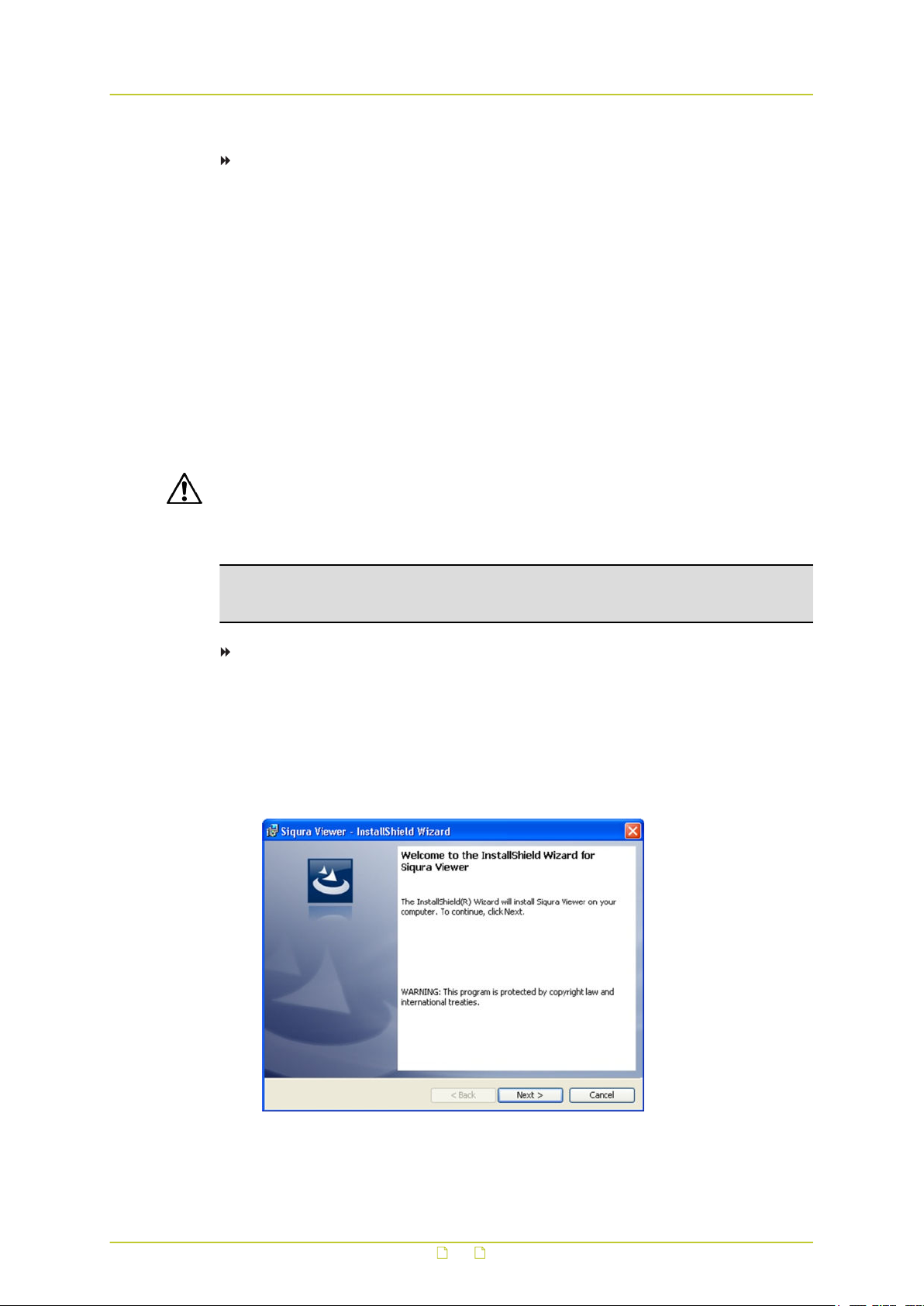
To install the Viewer software
1 When prompted about the ActiveX control installation, allow the Viewer installation
wizard to make changes to your computer.
2 In the initial screen of the installation wizard, click Next.
A progress bar is displayed while the application is being installed.
3 When installation is complete, click Finish.
The camera’s web interface is displayed.
Viewer installation wizard
24
Page 25
Access the camera
6.7 Focus adjustment
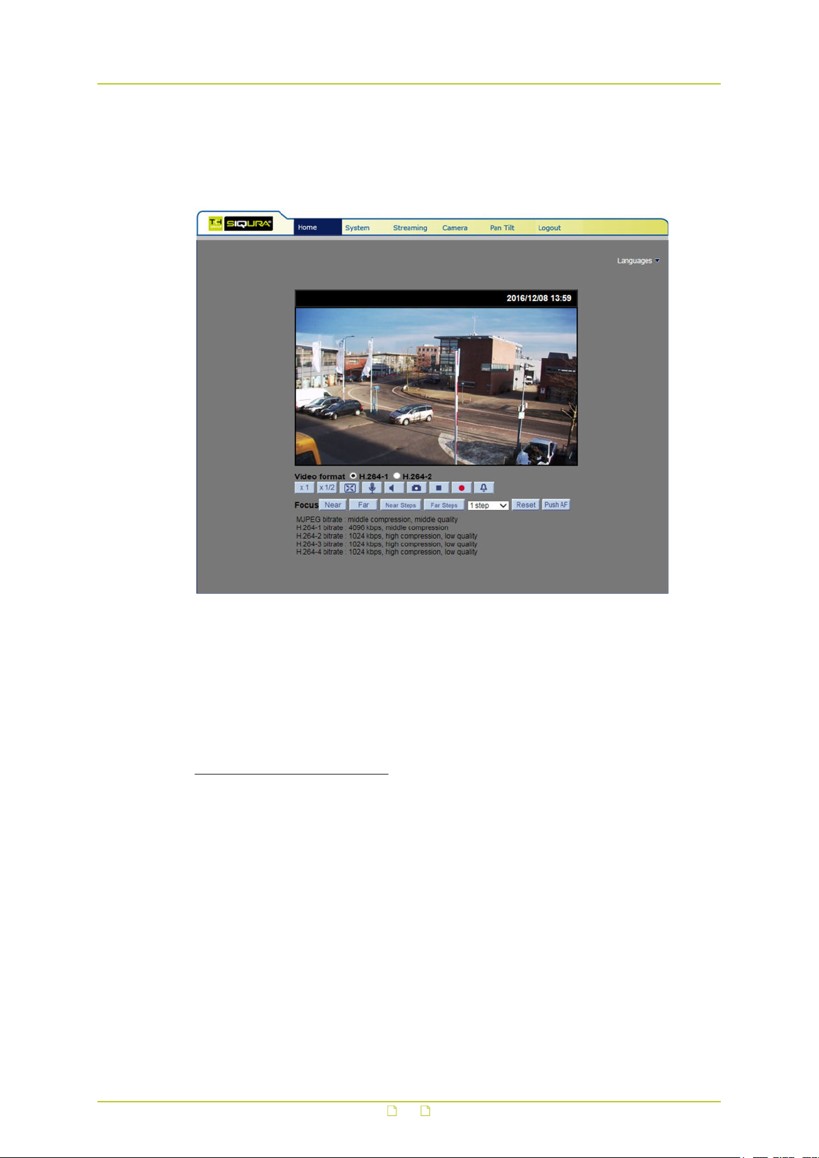
Once Viewer is successfully installed, the Home page of the camera is displayed as shown
below.
Use the focus buttons on this page to focus the camera properly. For more information about
the web interface of the camera, refer to the User Manual.
6.8 System compatibility
To ensure system compatibility, you are advised to download the latest BC820v2 firmware at
www.tkhsecurity.com/support-files
.
25
Page 26
Appendix: Enable UPnP in Windows 7
With UPnP enabled in Windows, it is possible to see TKH Security devices in Windows
Explorer. You can double-click a device to open its webpages.
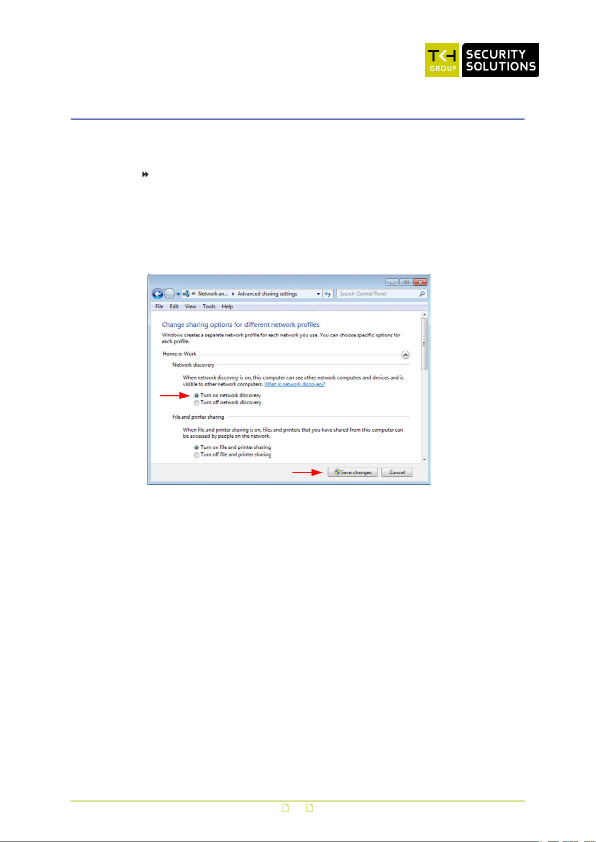
To enable UPnP in Windows 7
1 In Control Panel, click Network and Sharing Center.
2 In the left pane, click Change advanced sharing settings.
3 Under the relevant network profile, click Turn on network discovery.
4 Click Save changes
UPnP will now automatically start when you turn on your computer.
Enable network discovery
26
Page 27

Appendix: Delete Viewer
Viewing camera images in the BC820v2 webpages requires Viewer software. We strongly
advise you to remove a previous installation of Viewer from your computer before you access
the camera over the network for the first time or when you encounter an "A new version is
available" message.
To uninstall Viewer
1 On the Windows Start Menu, click Control Panel.
2 Click Programs and Features.
3 On the Uninstall or change a program page, select Viewer from the list of installed
programs.
4 Click Uninstall.
Deleting the files in your Temporary Internet Files folder may improve your web browser
performance.
To delete the Temporary Internet files
1 Open your web browser.
2 On the Tools menu, click Internet Options.
3 In the Browsing history section of the General tab, click Delete.
4 Select Temporary Internet files, and then click Delete.
27
Page 28

Appendix: Set up Internet security
If ActiveX control (Viewer) installation is blocked, set the Internet security level to default or
change the ActiveX controls and plug-ins settings.
To set the Internet Security level to default
1 Start Internet Explorer (IE).
2 On the Tools menu, select Internet Options.
3 Click the Security tab, and then select the (logo of the) Internet zone.
4 Under Security level for this zone, click the Default Level button.
5 Click OK to confirm the setting.
6 Close the browser window, and start a new session to access the BC820v2.
To modify ActiveX Controls and Plug-ins settings
1 Start Internet Explorer (IE).
2 On the Tools menu, select Internet Options.
3 Click the Security tab, and then select the (logo of the) Internet zone.
4 Under Security level for this zone, click the Custom Level button.
The Security Settings - Internet Zone dialog box displays.
5 Under ActiveX controls and plug-ins, set all items listed below to Enable or Prompt.
Note that items may vary from one IE version to another.
Allow previously unused ActiveX controls to run without prompt.
Allow Scriptlets.
Automatic prompting for ActiveX controls.
Binary and script behaviors.
Display video and animation on a webpage that does not use external media player.
Download signed ActiveX controls.
Download unsigned ActiveX controls.
Initialize and script ActiveX controls not marked as safe for scripting.
Run ActiveX controls and plug-ins.
Script ActiveX controls marked safe for scripting.
6 Click OK to accept the settings and close the Security Settings dialog box.
7 Click OK to close the Internet Options dialog box.
8 Close the browser window, and start a new session to access the BC820v2.
28
Page 29

Index
A
About this manual.................................... 4
Access the camera..................................20
Appendix: Delete Viewer..........................27
Appendix: Enable UPnP in Windows 7........ 26
Appendix: Set up Internet security............28
B
Back panel.............................................15
C
Cautions................................................. 8
Change network settings with Device
Manager................................................22
Compliance............................................. 9
Connect alarm I/O.................................. 18
Connect audio........................................ 18
Connect data......................................... 19
Connect the camera................................15
Connect to network.................................17
Connect via web browser......................... 21
Product overview.................................... 10
Protection against overvoltage................... 7
S
Safety.....................................................5
Safety and compliance.............................. 5
System compatibility...............................25
System requirements.............................. 20
D
Description............................................ 11
Dimensions............................................12
F
Find the unit with Device Manager............ 21
Focus adjustment................................... 25
I
Install the camera...................................13
Install Viewer.........................................24
L
Light sensor...........................................16
Log on to the unit................................... 23
M
microSD Card.........................................19
Models.................................................. 10
Mount the camera...................................13
Mount the lens....................................... 13
P
Package contents....................................12
Power the camera...................................17
29
 Loading...