

TJERNLUND IL, XL MOTOR KIT 8504051 REV. 2 1196, 950-4020 I, I, XL User Manual
TJERNLUND PRODUCTS, INC.
1601 Ninth Street • White Bear Lake, MN 55110-6794
PHONE (800) 255-4208 • (651) 426-2993 • FAX (651) 426-9547
Visit our web site • www.tjernlund.com
MODEL I, IL, XL REPLACEMENT MOTOR KIT
1. Disconnect power supply before making wiring connections to prevent electrical shock
and equipment damage.
2. All wiring must comply with applicable codes and ordinances.
3. When wiring is completed, check all components by running system through its entire
heating cycle.
4. Check vent pipe system for leakage. All vent system leaks must be sealed prior to the
installation of the Draft Inducer.
5. Flue gas temperature must not exceed 575o F at Draft Inducer inlet.
MOTOR KIT INSTALLATION INSTRUCTIONS
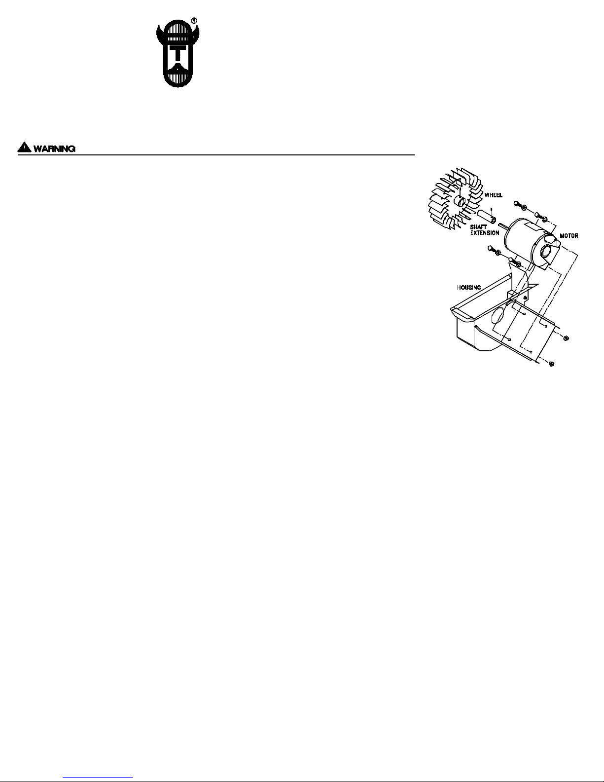
1. To remove defective motor from unit, loosen set screw(s) on Draft Inducer wheel hub.
2. Loosen bolts which attach motor to motor mount. Slide shaft extension out of wheel and
remove defective motor from unit. NOTE: USE CARE SO FASTNERS ARE NOT LOST.
3 Loosen set screw(s) which attach shaft extension to motor shaft. Remove shaft extension.
4. Insert shaft extension onto new motor shaft. Secure shaft extension by tightening set screw(s).
5. To ensure proper performance and extended bearing life of the motor, inspect wheel and clean if necessary. Refer to the
installation instructions of your unit for proper maintenance procedures.
6. Position motor onto motor mount, being sure motor shaft (with shaft extension) is fitted into Draft Inducer wheel.
7. Firmly fasten motor to motor mount with wrench, using proper bolts, washers and nuts removed in step 2.
8. Secure Draft Inducer wheel by tightening set screw(s) onto shaft extension. Spin the wheel by hand to ensure proper
alignment and equal blade clearance on both housing sides.
9. Wire Draft Inducer according to appropriate diagram on back. If appropriate circuit does not appear, consult Tjernlund
Products, Inc. at 800-255-4208. UNIT MUST BE GROUNDED! All wiring must be done in accordance with the NEC and
applicable codes. The wiring from the appliance should be protected by overcurrent protection(fuses or circuit breakers) rated
15 amperes or less, as applicable for 14 AWG conductors. EXTREME CAUTION MUST BE EXERCISED TO ENSURE THAT
WIRING DOES NOT COME INTO CONTACT WITH ANY HEAT SOURCE.
10. Check heater and Draft Inducer operation. Vari-Draft control on Draft Inducer should be adjusted so that there is no spillage at
draft diverter, hood or barometric.
SERVICE
Specific instructions cannot be made concerning frequency of lubrication. Usually, oiling every three months during heating sea son should be sufficient. NO MORE THAN 3 DROPS OFS.A.E. 20 OIL SHOULD BE USED. Oil holes or lances are provided at
front and rear faces of motor.
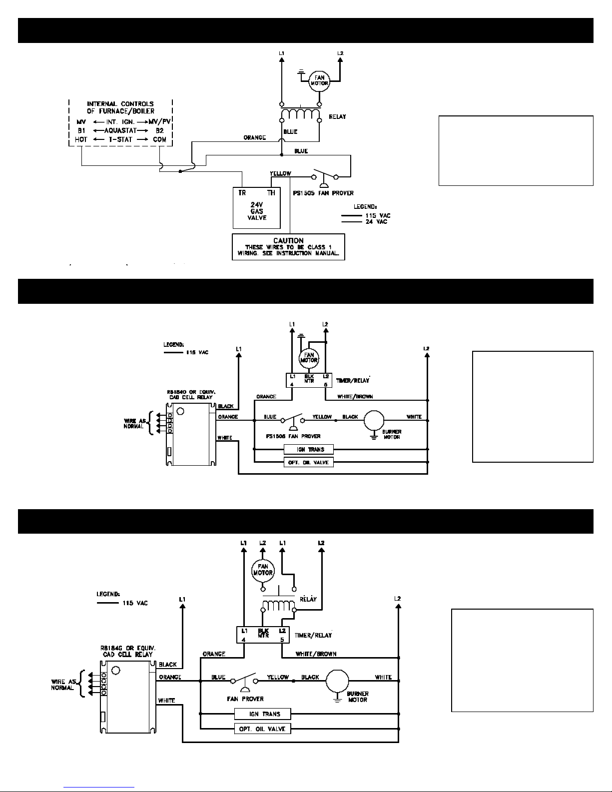
GAS WIRING TO ANY APPLIANCE EQUIPPED WITH 24V CONTROLS
NO POST-PURGE RELAY/TIMER ON DRAFT INDUCER
COMPONENTS NEEDED:
(1) DRAFT INDUCER
(1) PS1505 FAN PROVER
(1) 24/115V RELAY
USE 950-1040 FOR MODELS DJ3 & D3
USE 950-1016 FOR MODELS I, IL, XL
DRAFT INDUCER CONNECTED TO OIL BURNER WITH R8184G CONTROLS
(DRAFT INDUCER MOTOR LESS THAN 4.4 AMPS) INCLUDES MODELS UP TO THE D3
COMPONENTS NEEDED:
(1) DRAFT INDUCER
(1) PS1505 FAN PROVER
(1) 950-1067 RELAY/TIMER
MAXIMUM AMP LOAD IS
4.4 AMPS
USE DIAGRAM BELOW IF
DRAFT INDUCER MOTOR
IS GREATER THAN 4.4 AMPS
DRAFT INDUCER CONNECTED TO OIL BURNER WITH R8184G CONTROLS
(DRAFT INDUCER MOTOR GREATER THAN 4.4 AMPS) INCLUDES THE MODELS I, IL, XL
COMPONENTS NEEDED:
(1) DRAFT INDUCER
(1) PS1505 FAN PROVER
(1) 950-1067 RELAY/TIMER
MAXIMUM AMP LOAD IS 4.4 AMPS
(1) HONEYWELL R4222B1082 RELAY
OR EQUIVALENT
(INSTALLER SUPPLIED)
REV. 2, 11/96 © 1996 TJERNLUND PRODUCTS, INC. P/N 8504051
 Loading...