

Page 1

Copyright © 2011, Tjernlund Products, Inc. All rights reserved P/N 8504175
OWNER INSTRUCTIONS, DO NOT DESTROY
Recognize this symbol as an indication of important Safety Information!
THESE INSTRUCTIONS ARE INTENDED AS AN AID TO QUALIFIED, LICENSED
SERVICE PERSONNEL FOR PROPER INSTALLATION, ADJUSTMENT AND
OPERATION OF THIS PRODUCT. READ THESE INSTRUCTIONS THOROUGHLY
BEFORE ATTEMPTING INSTALLATION OR OPERATION. FAILURE TO FOLLOW
THESE INSTRUCTIONS MAY RESULT IN IMPROPER INSTALLATION, ADJUSTMENT, SERVICE OR MAINTENANCE POSSIBLY RESULTING IN FIRE, ELECTRICAL SHOCK, CARBON MONOXIDE POISONING, EXPLOSION, PERSONAL
INJURY OR PROPERTY DAMAGE.
!
DO NOT DESTROY. PLEASE READ CAREFULLY AND
KEEP IN A SAFE PLACE FOR FUTURE REFERENCE.
MODEL XCOP1
INSTALLATION INSTRUCTIONS
REV. 3/11
TJERNLUND PRODUCTS, INC.
1601 Ninth Street • White Bear Lake, MN 55110-6794
PHONE (800) 255-4208 • (651) 426-2993 • FAX (651) 426-9547
Visit our web site • www.tjernlund.com
SENSING
PORT
INTERIOR VIEW
Page 2
1
TABLE OF CONTENTS
Page (s)
Description and General Information...............................................................................................................................1
Installation Restrictions and Cautions ............................................................................................................................1
Sizing a Common Manifold Serving Multiple Dryers ......................................................................................................2
XCOP1 Installation .........................................................................................................................................................2
Wiring Connections between XCOP1 and RT-Series Rooftop Fan ................................................................................3
Sensing Sampling Tube Location & Installation..........................................................................................................4, 5
Adjusting The Pressure (Exhaust) Set Point & Balancing Individual Connections..........................................................5
Adjustment of Balancing Baffle(s) For Kitchen and Bath Fans .......................................................................................5
Troubleshooting, Service and Warranty......................................................................................................................5, 6
Tjernlund Products welcomes your comments and questions. Address all correspondence to:
Customer Service • Tjernlund Products, Inc. • 1601 Ninth Street • White Bear Lake, MN 55110-6794
Call us toll free at 800-255-4208, visit our web site @ www.tjernlund.com or email us at fanmail@tjfans.com.
DESCRIPTION
The XCOP1 is a Constant Operating Pressure Control that will modulate the speed of an RT-Series Rooftop exhaust fan to maintain a user adjustable negative pressure set point. The set point is adjusted through a pot mounted on the COP circuit board. The
operating range of the XCOP1 control is -0.10 to -1.0” w.c.. Do not use with any other series of Tjernlund Inducers/Venters.
Pressure is measured in a chase or duct at the farthest point from the exhaust fan with the included sensing tube and tubing which
connects to the pressure sensing port on the XCOP1. As exhaust volume increases within the duct/chase the resulting reduction in
measured pressure causes the XCOP1 control to increase power to the fan. It speeds up to handle the additional exhaust volume
and slows down when the exhaust volume is reduced, modulating fan speed to maintain a constant exhaust pressure.
GENERAL INFORMATION
Each XCOP1 is electrically factory line tested before shipment.
After opening carton, inspect thoroughly for hidden damage. If any damage is found notify freight carrier and your distributor
immediately and file a concealed damage claim.
INSTALLATION RESTRICTIONS
1. Do not use the XCOP1 to control the draft of gas or oil fired heating equipment. Draft applications for gas and oil heaters require
the burner interlock of the Draft Cop model DCOP1 controller.
2. The XCOP1 is intended for indoor installation only. Do not mount the XCOP1 on a heat source that exceeds 140
O
F (60OC).
3. The maximum distance wire can be ran from the RT-Series Fan junction box to the XCOP1 control is 250 feet.
CAUTIONS
The XCOP1 must be installed by a qualified installer (an individual properly licensed and/or trained) in accordance with all local
codes or, in their absence, in accordance with the National Electrical Code. Failure to install, maintain and/or operate the XCOP1
in accordance with manufacturer's instructions may result in conditions which can produce bodily injury and property damage.
1. Disconnect power supply from the XCOP1 when making wiring connections and servicing the XCOP1. Failure to do so may
result in personal injury and/or equipment damage.
2. All installation restrictions and instructions in the RT-Series Fan installation instructions must be followed when using the
XCOP1.
3. Make certain power source is adequate for the XCOP1 and RT-Series Fan requirements. Do not add equipment to a circuit
when the total electrical load is unknown.
Page 3
2
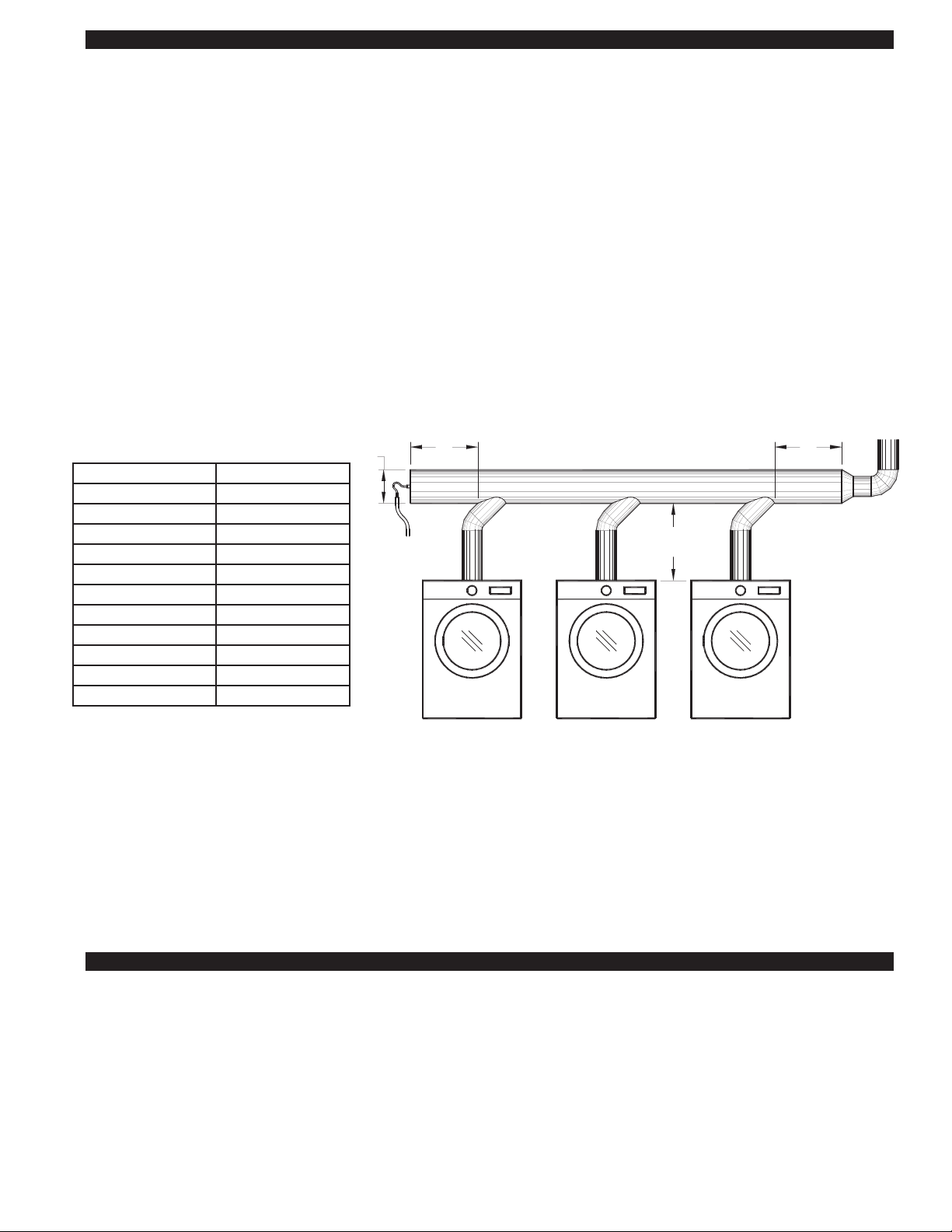
SIZING A COMMON VENT MANIFOLD SERVING MULTIPLE DRYERS
The most important step towards assuring that individual dryers vented into a common manifold exhaust smoothly is to size the
manifold large enough to reduce the affects that velocity in the manifold has on the junctions of the dryer vent connections.
Exhaust moving too quickly in a common vent manifold can amplify the exhaust at vent connectors by aspirating across the connector opening and creating an amplified siphon affect. With a properly sized common vent manifold, velocities are maintained
below the point where they have a significant affect on the exhaust of the individual dryer connections.
It is important to note that these sizing recommendations are for the common vent manifold only and that the typically smaller minimum vent diameter listed in the RT-Series Fan selection table may be used for the remainder of the horizontal vent and chimney.
The larger diameter vent manifold should extend at least 2 diameters beyond the last dryer connection point.
1. When in doubt, get help from Tjernlund Tech Service at 800-255-4208, push 0 and ask for technical assistance or email
fanmail@tjfans.com with details of the job.
2. When possible use 45
O
Manifold Tee connections to the common vent manifold in the direction of the RT-Series Fan instead of
90OTee connections.
3. If possible, locate larger exhaust volume vent connections closer to the RT-Series Fan. This reduces the affect of their exhaust
on smaller volume connections.
4. The size of the common vent manifold should be at least 90% of the total area of all individual vent connections. See example
below.
Example: A vent layout is required for a job that consists of 3 dryers with 6” diameter outlets.
Add these areas together:
3 x 0.1964 = 0.5892
Total Area = 0.5892 Square Feet x 0.90 (90%) = 0.530. In looking at the table above, this area is greater than an 8" diameter pipe
but smaller than a 10" diameter pipe. 10" diameter vent is the minimum size the common vent manifold diameter should be. It is
perfectly acceptable to be larger than this area if desired. It is also acceptable to have this area be reduced as the vent system
works backward towards the appliance furthest from the RT-Series Fan. In this example, the common vent manifold should extend
at least 20" past the connection point of the dryer farthest from the RT-Series Fan.
XCOP1 INSTALLATION
Do not mount the XCOP1 junction box on a heat source that exceeds 140OF (60OC). Examples of improper mounting surfaces
include vent pipe, top of heater casing or any place where radiant or convective heat would cause the junction box temperature to
exceed 140
O
F (60OC). The XCOP1 is intended for indoor installation only.
Using the key hole slots on the back of the XCOP1 junction box as a template, mark 4 holes on the mounting surface, drill pilot
holes if necessary, and secure junction box using provided screws.
E
Breech Size Diameter Area (Square Feet)
3”
0.0491
4” 0.0873
5” 0.1364
6” 0.1964
8” 0.3491
10” 0.5454
12” 0.7854
14” 1.0690
16” 1.3960
18” 1.7670
20” 2.1820
D
2D
MINIMUM
2D
MINIMUM
COMMON VENT MANIFOLD
MAINTAIN THE DRYER
OUTLET DIAMETER UNTIL
THE COMMON MANIFOLD
FIGURE 8054009 4/14/11
DRYER FURTHEST
FROM THE INDUCER
SENSING TUBING
TO XCOP1
DRYER FURTHEST
FROM ROOFTOP FAN
Page 4
3
The XCOP1 must be installed by a qualified installer (an
individual properly licensed and/or trained) in accordance
with all local codes or, in their absence, in accordance with
the National Electrical Code.
All wiring from the XCOP1 to the RT-Series Fan junction box
must be appropriate Class 1 wiring as follows: installed in
rigid metal conduit, intermediate metal conduit, rigid nonmetallic conduit, electrical metallic tubing, Type MI Cable,
Type MC Cable, or be otherwise suitably protected from
physical damage.
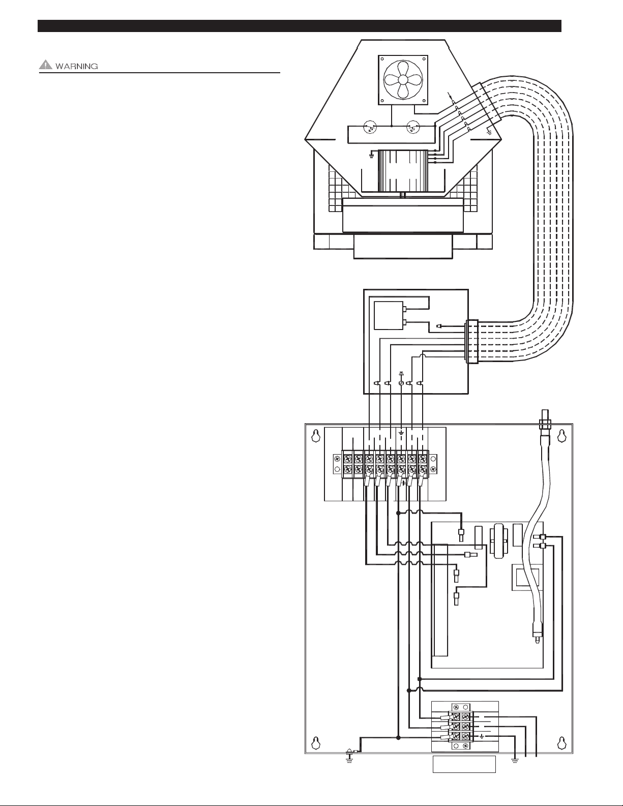
COP CONTROL POWER CONNECTIONS
Connect 115 VAC supply voltage to L & N terminals and
Ground wire to ground on COP control terminal block.
Important: Installer must supply overload and disconnect
protection. COP Control power may be switched through a
building management system, pressure switch or other 115
VAC switch.
RT-SERIES MOTOR & COOLING FAN CONNECTIONS
NOTE: The maximum distance wire can be ran from the
RT-Series Rooftop Fan 4 x 4 Junction box to the XCOP1
control is 250 feet.
Cut Orange motor capacitor wire in RT-Series fan provided
4 x 4 Junction box and cap end with a wire nut that previously went to RT-Series Inducer motor.
Connect the Orange Motor Capacitor lead to the MOTOR
ORG location on COP terminal strip.
Connect Red and White/Red motor leads from RT-Series
Fan whip to MOTOR RED and WHT/RED location on COP
terminal strip.
Connect the Black & White Cooling Fan leads to COOL FAN
WHT and BLK location on COP terminal strip.
4 FT. WHIP
PRE-WIRED
N.O. COM ORG RED WHT BLK
1303284
WHT/
GRN
RED
PROVER MOTOR COOL FAN
P2
T11
P1
T7
N
GRN
L
WHT/RED
YEL
ORG
BLU
RED
WHT
BLK
T14
BLK
WHT
GRN
L
N
1303285
T14
T11
T7
T10
WHITE / RED
ORG
RED
GROUND
INCLUDED
NL1
COP
POWER SUPPLY
MOTOR
CAPACITOR
GROUND
WHITE
BLACK
RED
BROWN
WHITE / RED
COOLING FAN
THERMOSTAT
INDUCER
MOTOR
THERMOSTAT
WHT / RED
BLACK
BROWN
ORANGE
BROWN
RED
NUTS
ORANGE
BLACK
RED
WHT / RED
WHITE
WHITE
BLUEBLUEBLACK
INCLUDED 4 X 4 BOX
IMPELLER
WIRE
BLACK
ORANGE
ORANGE
SIDE VIEW
CUTAWAY
RT SERIES
WHITE
BLK
T9
T6
WIRING CONNECTIONS BETWEEN XCOP1 AND ROOFTOP RT-SERIES FAN
POWER SUPPLY
MAY BE SWITCHED
Page 5
4
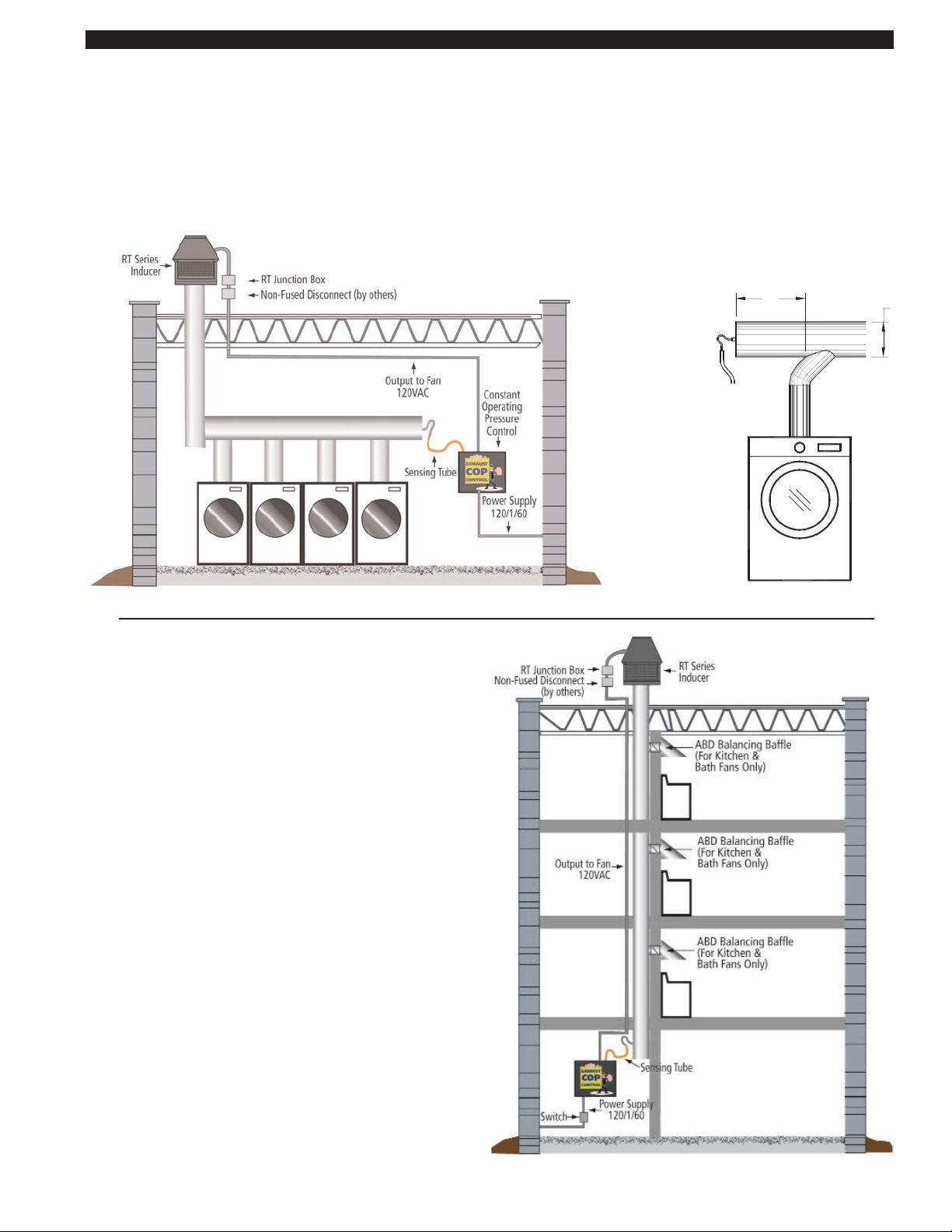
PRESSURE SENSING TUBE LOCATION
MULTIPLE DRYERS JOINED IN A COMMON HORIZONTAL DUCT
The sensing tube should be installed in the cap of a tee or at the rear of a common exhaust manifold, in back of the vent connector
that is farthest from the RT-Series Fan. The tee is necessary so that only static pressure is measured, (See Diagram A). If the
pressure sensing tube is installed in the side of a duct it will also measure velocity pressure, giving an incorrect signal back to the
XCOP1 Control. If mounting on the side of the duct is unavoidable, the sensing tube should be flush to the interior wall of the duct.
Avoid sampling near or in elbows. Duct connections should be sealed to prevent leakage or entrainment. Installer must provide
access for lint clean out.
MULTIPLE DRYERS, KITCHEN OR BATH FANS EXHAUSTED
INTO A COMMON VERTICAL CHASE
The sensing tube should be installed to sample the chase pressure at a point below the lowest duct connection but above any
point in the clean out that may accumulate moisture or lint. If
sampling pressure in the side of a chase the sensing tube end
should be flush to the interior wall of the chase, (See Diagram B).
Duct connections should be sealed to prevent leakage or entrainment of air. Installer must provide access for lint clean out.
BEHIND THE DRYER FURTHEST FROM INDUCER
BE LOCATED TWICE THE MANIFOLD DIAMETER
IF POSSIBLE, THE SENSING TUBE SHOULD
D
2D
DRYER FURTHEST
FIGURE 8054008 4/14/11
FROM THE INDUCER
MINIMUM
XCOP1
SENSING
TUBING TO
DIAGRAM A
DIAGRAM B
Chase Exhaust for Kitchens & Baths or Dryers
Multiple Clothes Dryers Common Vented
DRYER FURTHEST
FROM ROOFTOP FAN
Page 6
5
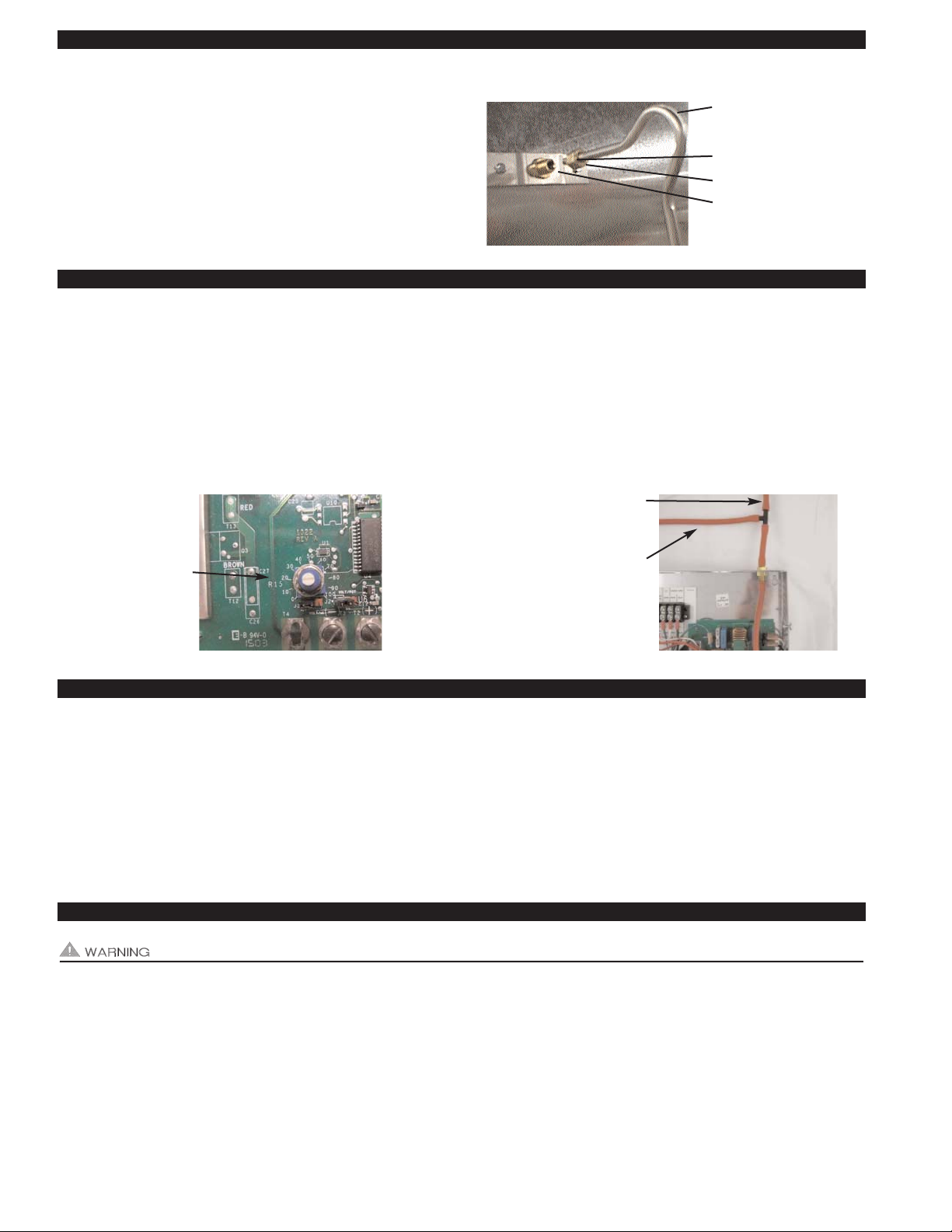
PRESSURE SENSING TUBE INSTALLATION
1. Follow sensing tube location recommendations on page 4.
Use a sharp drill bit to reduce burr, drill a 1/4" hole for pressure
sensing tube. Screw sensing tube bracket to duct/chase with
sampling hole centered, (See Diagram C).
2. Insert stainless steel sensing tube through 1/4" hole enough to
just penetrate interior of duct/chase and lock in place with compression ferrule and nut, (See Diagram C).
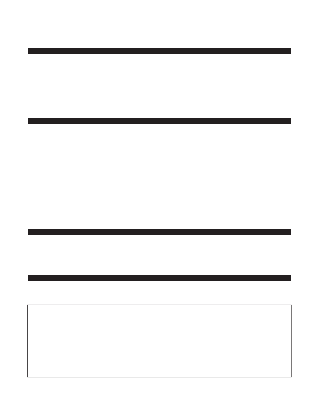
ADJUSTING THE PRESSURE (EXHAUST) SET POINT
1. Verify that slot on set point adjustment pot for the COP controller is aligned with the "20" hash mark, (See Diagram D).
2. Provide power to the XCOP1 by turning on circuit breaker or disconnect or activating dryers if using a dryer duct pressure switch.
3. Verify that the RT-Series Fan activates by seeing the draft pressure increase (more negative) on your draft gauge as measured
with a tee at draft sensing position, (See Diagram E). Gradually adjust the pot on the XCOP1 controller circuit board clockwise.
The RT-Series Fan should speed up increasing the negative exhaust pressure. Slowly adjust the pot on the XCOP1 controller
counter-clockwise until the exhaust pressure is maintained at -0.10" w.c.. NOTE: Turning the adjustment pot too far counterclockwise will cause the RT-Series Fan to stall or not be able to start. Readjust clockwise if necessary.
ADJUSTMENT OF BALANCING BAFFLE(S) FOR KITCHEN AND BATH FANS
IMPORTANT: Balancing Baffles must not be used for dryer applications due to the potential for lint buildup.
1. With all balancing baffles closed and starting with connection at lowest floor drill a small sampling hole in duct connection to the
chase 1 foot behind the Balancing Baffle (opposite side of chase connection).
2. With the XCOP1, RT-Series Fan and Bath/kitchen fans connected to the duct operating, gradually open the Balancing Baffle
until desired negative exhaust pressure is measured and lock in place. Typically a measurement of a -0.02 to -0.05" w.c. is
adequate.
3. Repeat steps 1 and 2 for each floor, moving up towards the RT-Series Fan.
TROUBLESHOOTING ELECTRICAL PROBLEMS
It is necessary to measure voltage during troubleshooting. Extreme caution must be exercised to prevent injury. If you are
unable to determine the defective part with the use of this guide, call your Tjernlund distributor or Tjernlund Products direct at
1-800-255-4208 for further assistance.
RT-SERIES FAN MOTOR DOES NOT OPERATE
Verify the XCOP1 control has power by checking for 115 VAC at the input power terminal strip positions L1 and N. If no voltage is
measured check circuit breaker, disconnect switch or any other switch between disconnect and XCOP1 control.
Voltage present: Verify wiring connections between XCOP1 and RT-Series Fan. Check adjustment pot on XCOP1. Too low of an
adjustment may stall RT-Series Fan. Adjust clockwise to see if RT-Series Fan speeds up. If RT-Series Fan does not speed up and
DIAGRAM C
1/4” STAINLESS STEEL
SENSING TUBE BEND MUST
FACE UPWARD
COMPRESSION FERRULE
COMPRESSION NUT
SAMPLING PORT CENTERED
OVER 1/4” HOLE
DIAGRAM E
TO PRESSURE SENSING
TUBE IN VENT COMMON
MANIFOLD
TO DRAFT GAUGE
DIAGRAM D
XCOP1 DRAFT
ADJUSTMENT POT
AND SCALE. CLOCKWISE WILL INCREASE
DRAFT.
Page 7
6
there is 115 VAC across the T6 and T9 terminals on XCOP1 control, verify that RT-Series Fan motor capacitor is good.
Disconnect the wire from capacitor that is connected to the ORG Motor terminal on XCOP1 control. Reconnect Orange wire from
RT-Series Fan capacitor in 4 x 4 electrical box to the Orange wire that should be capped off coming from RT-Series Fan whip.
Remove the Red and White/Red leads that were connected to the MOTOR RED and WHT/RED connection on XCOP1 and provide 115 VAC to them. If motor runs, replace COP control circuit board part number 950-8805. If motor does not run, verify capacitor is good. Replace RT-Series Fan capacitor or motor if necessary.
HOW TO OBTAIN SERVICE ASSISTANCE
1. If you have any questions about your XCOP1 or if it requires adjustment or repair, contact your installer, contractor or service
agency.
2. If you require technical information contact Tjernlund Products, Inc. at 1-800-255-4208 with the following information.
1. Model of the RT-Series Fan that XCOP1 is interlocked with as shown on the label attached to RT-Series Fan.
2. Name and address of installer and any service agency who performed work on the system.
3. Date of original installation and dates any service work was performed.
4. Details of the problem as you can best describe them.
LIMITED PARTS WARRANTY AND CLAIM PROCEDURE
Tjernlund Products, Inc. warrants the components of the XCOP1 for one year from date of installation. This warranty covers
defects in material and workmanship. This warranty does not cover normal maintenance, transportation or installation charges for
replacement parts or any other service calls or repairs. This warranty DOES NOT cover the complete XCOP1 if it is operative,
except for the defective part.
Tjernlund Products, Inc. will issue credit or provide a free part to replace one that becomes defective during the one year warranty
period. Proof of date of the installation in the form of the contractor sales/installation receipt is necessary to prove the unit has
been in service for under one year. All receipts should include the date code of the XCOP1 to ensure that the defective component
corresponds with the complete unit. This will help prevent possible credit refusal.
1.) Follow troubleshooting guide to determine defective component. If unable to determine faulty component, contact your
Tjernlund distributor or Tjernlund Technical Customer Service at 1-800-255-4208 for troubleshooting assistance.
2.) After the faulty component is determined, return it to your Tjernlund distributor for replacement. Please include XCOP1 date
code component was taken from. The date code is located on the Electrical Box cover. If the date code is older than one
year, you will need to provide a copy of the original installation receipt to your distributor. Credit or replacement will only be
issued to a Tjernlund distributor after the part has been returned prepaid to Tjernlund and verified defective.
WHAT IS NOT COVERED
Product installed contrary to our installation instructions, altered, neglected or misused
Product that has been wired incorrectly
Any freight charges related to the return of the defective part
Any labor charges related to evaluating and replacing the defective part
NO
T COVERED
REPLACEMENT PARTS
Component Part Number
COP Control Circuit Board 950-8805
TJERNLUND LIMITED ONE YEAR WARRANTY
Tjernlund Products, Inc. warrants to the original purchaser of this product that the product will be free from defects due to faulty material or workmanship for a period of (1) year from the date of original purchase or delivery to the original purchaser, whichever is earlier. Remedies under
this warranty are limited to repairing or replacing, at our option, any product which shall, within the above stated warranty period, be returned to
Tjernlund Products, Inc. at the address listed below, postage prepaid. THERE ARE NO WARRANTIES WHICH EXTEND BEYOND THE
DESCRIPTION ON THE FACE HEREOF, AND TJERNLUND PRODUCTS, INC. EXPRESSLY DISCLAIMS LIABILITY FOR INCIDENTAL OR
CONSEQUENTIAL DAMAGES ARISING FROM THE USE OF THIS PRODUCT. THIS WARRANTY IS IN LIEU OF ALL OTHER EXPRESS
WARRANTIES AND NO AGENT IS AUTHORIZED TO ASSUME FOR US ANY LIABILITY ADDITIONAL TO THOSE SET FORTH IN THIS LIMITED WARRANTY. IMPLIED WARRANTIES ARE LIMITED TO THE STATED DURATION OF THIS LIMITED WARRANTY. Some states do
not allow limitation on how long an implied warranty lasts, so that limitation may not apply to you. In addition, some states do not allow the
exclusion or limitation of incidental or consequential damages, so that above limitation or exclusion may not apply to you. This warranty gives
you specific legal rights and you may also have other rights which may vary from State to State. Send all inquiries regarding warranty work to
Tjernlund Products, Inc. 1601 9th Street, White Bear Lake, MN 55110-6794. Phone (651) 426-2993 • (800) 255-4208 • Fax (651) 426-9547 •
Email fanmail@tjfans.com.
 Loading...