

Page 1
TJERNLUND PRODUCTS, INC.
1601 Ninth Street • White Bear Lake, MN 55110-6794
PHONE (800) 255-4208 • (651) 426-2993 • FAX (651) 426-9547
Visit our web site • www.tjernlund.com
MODEL X2D
REV. C 07/14
INSTALLATION INSTRUCTIONS
OWNER'S INSTRUCTIONS, DO NOT DESTROY
THIS DEVICE MUST BE INSTALLED BY A
QUALIFIED PERSON.
READ INSTRUCTIONS CAREFULLY PRIOR TO
INSTALLATION AND OPERATION OF THE XCHANGER.
Copyright © 2014, Tjernlund Products, Inc. All rights reserved. P/N 8504164
Page 2
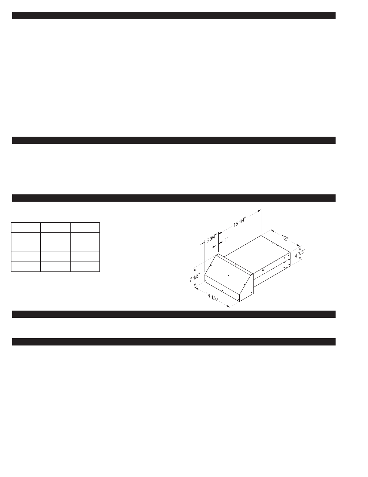
TABLE OF CONTENTS
Descriptions and Specifications.......................................................................................................................................1
Installation Restrictions....................................................................................................................................................1
Cautions ..........................................................................................................................................................................2
Recommended Methods and Patterns of Operation....................................................................................................2-3
Recommended Installation and Termination Locations................................................................................................3-4
X
CHANGER
Dehumidistat Control Module Installation & Operation ...................................................................................................6
X
CHANGER
TM
Installation..............................................................................................................................................4-6
TM
Ladder Diagram ........................................................................................................................................6
Maintenance ....................................................................................................................................................................7
How to Obtain Service & Warranty..................................................................................................................................7
Replacement Parts & Accessories ..................................................................................................................................7
X
CHANGER
TM
is a trademark of Tjernlund Products, Inc.
Tjernlund Products welcomes your comments and questions. Call us at (651) 426-2993, (800) 255-4208, Fax (651) 426-9547, email us
at fanmail@tjfans.com or write to: Customer Service, Tjernlund Products, Inc., 1601 Ninth Street, White Bear Lake, MN 55110-6794.
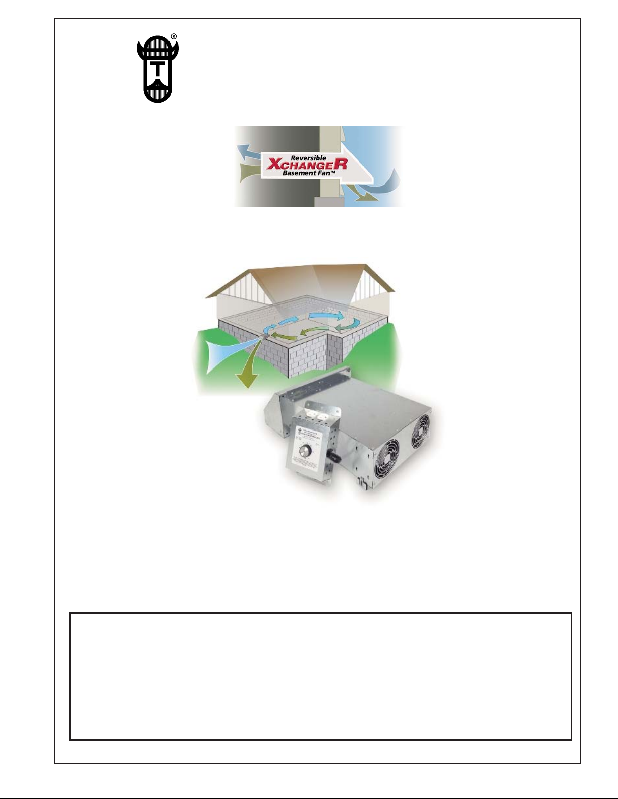
DESCRIPTION
The XCHANGERTMmodel X2D is a dual fan mechanical ventilator capable of exhausting inside air, providing fresh outside air or providing a balanced air exchange. The fans can be independently switched on or off or be easily reversed to provide fresh outside air or
exhaust inside air. The X2D includes a dehumidistat control which operates the fan(s) based on the relative humidity sensed by the
control inside the home. The dehumidistat control includes an “On” setting that will operate the fan(s) continuously or the switch can
be turned “Off” so the fan(s) do not operate during undesireable seasons. The XCHANGERTMcan also be operated by a standard
plug-in timer. Tjernlund’s optional SCP speed control kit is also available if desired.
SPECIFICATIONS
MODEL X2D XCHANGER
1 FAN 2 FANS
Voltage 120 120
Watts 20
Amps 0.3
CFM 90
40
0.6
180
Dehumidistat: 20% - 80% RH Range
Rough-in Wall Opening Dimensions: 12 1/4” x 5 1/4”
GENERAL INFORMATION
Each XCHANGERTMis electrically factory line tested before shipment. After opening carton, Inspect thoroughly for hidden damage.
INSTALLATION RESTRICTIONS
WARNING: Improper installation, adjustment, alterations, service or maintenance can cause injury or property damage. Refer to
this manual. For assistance or additional information consult a qualified installer, service agency or the equipment supplier.
WARNING: Sufficient air is needed for proper combustion and exhausting of gases through the flue (chimney) of fuel burning equip-
ment to prevent backdrafting. Follow the heating equipment manufacturer’s guideline and safety standards such as those
published by the National Fire Protection Association (NFPA), and the American Society for Heating, Refrigeration and
Air Conditioning Engineers (ASHRAE), and the local code authorities.
WARNING: Do not exhaust air from mechanical room unless makeup air is also supplied or equipment in mechanical room is sealed
combustion. Carbon monoxide poisoning may result. Use the DT2-6 6” duct take-off kit so exhaust can be removed from
outside the mechanical room if necessary.
Observe proper location of hood as described on page 3. The X
Only X
CHANGER
TM
fans can be plugged into dehumidistat control module or damage may result.
CHANGER
TM
must only be installed with the hood on an exterior wall.
Do not discharge intake air onto water pipes or other equipment which may be affected by temperature extremes.
1
Page 3
CAUTIONS
WARNING: Failure to install, maintain and/or operate the XCHANGERTMin accordance with manufacturer’s instructions may result in
conditions that can produce bodily injury and property damage.
Disconnect power supply to fans and/or control when reversing fan direction or servicing the X
CHANGER
TM
. Failure to do so may
result in personal injury and/or equipment damage.
Make certain the power source is adequate for the X
CHANGER
TM
requirements. Do not add the XCHANGERTMto a circuit where the
total electrical load is unknown.
XCHANGER DEHUMIDISTAT CONTROL MODULE OPERATION
The XCHANGERTMcontrol module includes an adjustable dehumidistat control which activates the fan(s) if
the relative humidity rises above the selected set-point. It is generally recommended to maintain a Relative
Humidity (RH) below 60% to inhibit mold growth. The dehumidistat can be turned fully clockwise to the ‘on’
position for constant fan(s) operation or it can be turned fully counter-clockwise to ‘off’ during seasons or times
when it is not desired for the X
CHANGER
TM
fan(s) to run. Each fan can be independently turned on/off by its fan
switch on control module.
STANDARD PLUG-IN TIMER OPERATION
A standard adjustable timer can also be utilized for timed operation of the XCHANGERTMfan(s). Plug timer into
standard outlet and plug XCHANGERTMcontrol module into wall timer. Turn dehumidistat control fully clockwise
to the ‘on’ position. Both outlets in XCHANGERTMcontrol module will be controlled by the wall timer. Each fan
can be independently turned on/off by its fan switch on dehumidistat control module. You can also allow the
dehumidistat control to turn the X
CHANGER
TM
on during certain times of the day if you use a timer and keep the
dehumidistat control at the desired set-point.
TJERNLUND OPTIONAL SCP SPEED CONTROL OPERATION
Tjernlund’s optional SCP speed control can be used to vary the speed of both XCHANGERTMfans. Plug SCP
speed control into standard outlet and plug XCHANGERTMcontrol module into SCP speed control. Both outlets in
XCHANGERTMcontrol module will be controlled by the SCP speed control. Each fan can be independently
turned on/off by its fan switch on dehumidistat control module.
RECOMMENDED PATTERNS OF OPERATION
The XCHANGERTMX2D model includes a dehumidistat control which can cycle the XCHANGERTMfan(s) automatically based on the relative humidity level of the house or it can be operated based on recommendations below. It is generally recommended to maintain a
Relative Humidity (RH) below 60% to inhibit mold growth.
A standard plug-in wall timer can be programmed based on the lifestyle or needs of the occupants. For example, a family with smokers may want to cycle the X
CHANGER
Another timed method may be to cycle the X
TM
more frequently than a family of non-smokers.
CHANGER
TM
during peak usage of exhaust fans, such as bathroom, kitchen, laundry or
utility. Outdoor air should be brought in at these peak times to help balance out pressure inside the house.
The XCHANGERTMcan be cycled on and off at regular intervals to periodically provide fresh air to the home, exhaust stale air or have
one fan bring air in and the other fan exhaust air for a balanced air exchange. It can also be ran like an economizer to bring outside
air in during evening time when it is cooler outside.
HYPOTHETICAL XCHANGER OPERATION BASED ON LIFESTYLE
The example below shows a possible way in which cycling times of the XCHANGERTMmay be determined based on household
occupant lifestyles.
6:00 A.M. to 9:00 A.M. = Outside fresh air should be brought into the house to compensate for morning routines. Bathing, cooking,
laundry and other activities such as smoking necessitate that outside fresh air to be brought in. Depressurization of the house at these
times is common with many exhaust fans running at one time.
9:00 A.M. to 4:00 P.M. = House is normally vacant with occupants at work or school. Cycle X
CHANGER
TM
on and off for 15 minute
intervals per hour to assure fresh air is supplied to the house.
4:00 P.M. to 8:00 P.M. = Outside fresh air should be brought into the house to compensate for evening routines. Bathing, cooking,
laundry and other activities such as smoking necessitate that outside fresh air to be brought in. Depressurization of the house at these
times is common with many exhaust fans running at one time.
8:00 P.M. to 6:00 A.M. = All members of the household are usually present. Outside fresh air is needed to dilute occupant generated
carbon dioxide during sleeping. Cycle X
CHANGER
TM
on and off for 15 minute intervals, with occasional 30 minute intervals to assure
fresh air is supplied to house.
2
Page 4

XCHANGER OPERATION BASED ON AIR CHANGES PER HOUR
This method of operation can be used to supplement or provide for guaranteed air change rates. Table 1 shows the constant Cubic
Feet Per Minute (CFM) of air necessary to produce the desired Air Change Per Hour rate (ACH), assuming natural infiltration of outside air at a rate of .10 ACH. Square footage is determined by calculating the finished living space of the house. Garages and crawl
space should not be included. The constant CFM figures shown assume that the living space has standard 8 foot ceilings.
TABLE 1
1. Determine square footage of house living space on left hand column.
2. Pick desired air change rate from top row.
3. Locate intersection of these points to determine constant CFM that should be obtained to meet desired ACH.
CHANGER
The X
TM
ER
exceeds that listed in Table 1, a standard plug-in timer can be set so the XCHANGERTMis cycled to obtain the
TM
will provide 180 CFM with both fans and 90 CFM with one fan operating. Where the CFM delivery of the XCHANG-
desired ACH or Tjernlund’s optional SCP speed control may be used.
EXAMPLE
3000 square feet of living space
.2 ACH desired ventilation rate equals 40 CFM
CHANGER
X
In this example the plug-in timer may be set so that the X
TM
capacity of 90 CFM (with one fan running)
CHANGER
TM
operates for one half hour straight each hour or two fifteen
minute periods each hour.
RECOMMENDED INSTALLATION LOCATION
The XCHANGERTMmay be mounted anywhere in the house. The best place to mount it is the basement through the rim joist on top of
the foundation wall.
WARNING: Do not exhaust air from mechanical room unless makeup air is also supplied or equipment in mechanical room is sealed
combustion. Carbon monoxide poisoning may result. Use the optional DT2-6 6” duct take-off kit so exhaust can be
removed from outside the mechanical room if necessary.
It is required that the X
CHANGER
TM
be installed in a location where it will not be directed at the occupants. Do not discharge intake air
onto water pipes or other equipment which may be affected by temperature extremes.
Do not terminate adjacent to thermostat. Outside temperatures can disrupt normal thermostat operation.
Do not terminate within three feet from a barometric draft control or intake grille of a heating appliance.
XCHANGER HOOD TERMINATION CLEARANCES
Install XCHANGERTMin accordance with BOCA national Mechanical Codes M-306.1 and M-306.1.1 as follows, (See Diagram A).
M-306.1 LOCATION: Outside air exhaust and intake openings shall be located a minimum of 10 feet (3048mm) from lot lines or buildings on the same lot. When openings front on a street or public way, the distance shall be measured to the centerline of the street or
public way.
M-306.1.1 INTAKE OPENINGS: Outside air intake openings shall be located a minimum of 10 feet (3048mm) from any hazard or
noxious contaminant such as vents, chimneys, plumbing vents, streets, alleys, parking lots and loading docks. When a source contaminant is located within 10 feet (3048mm) of an intake opening, such opening shall be located a minimum of 2 feet (610mm) below
the contaminant source.
IN ADDITION TO THESE CODES THE MANUFACTURER RECOMMENDS THAT:
• The X
CHANGER
TM
hood should be a minimum of 1 foot above grade or anticipated snow line.
• The XCHANGERTMhood should be a minimum of 3 feet from an inside corner of the building.
3
Page 5
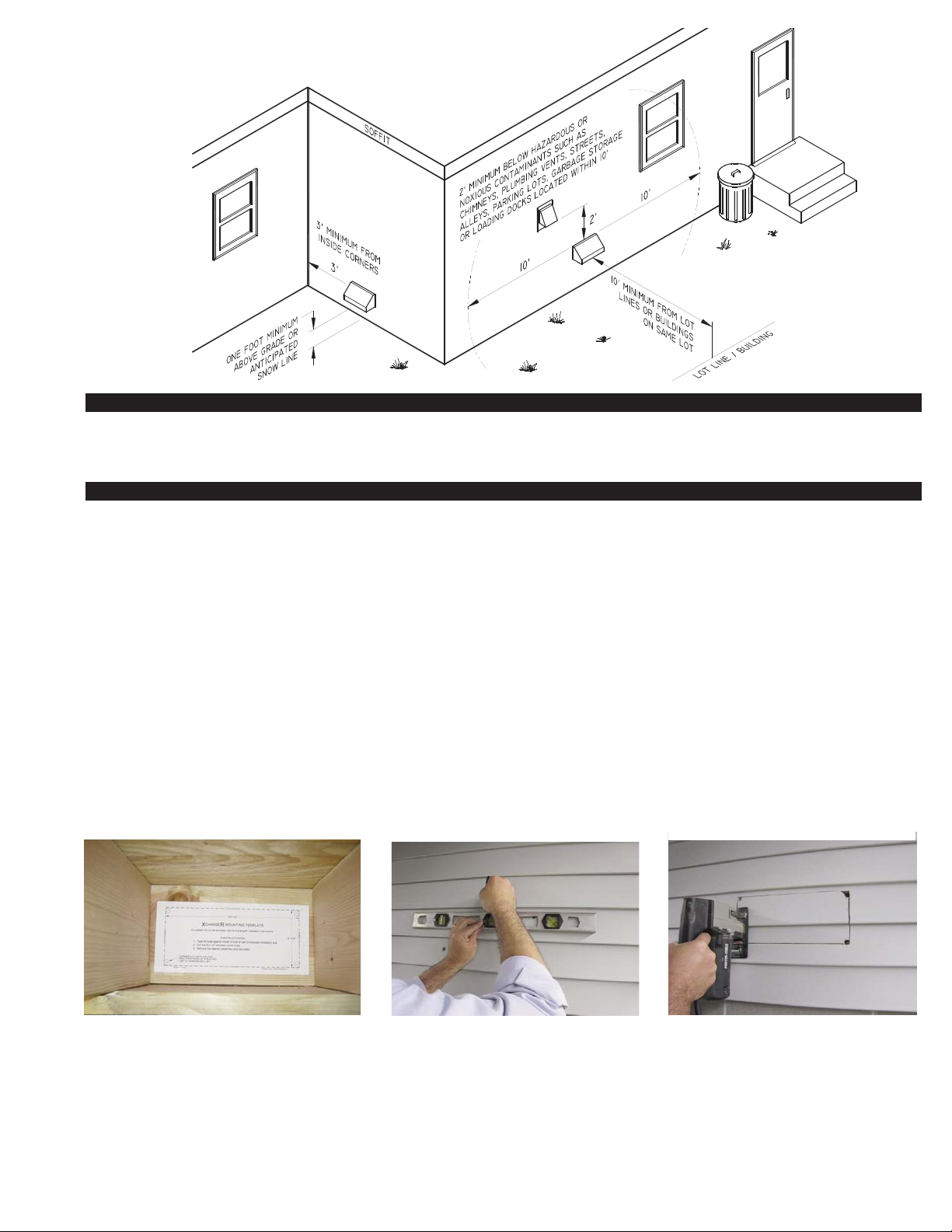
DIAGRAM A
INSTALLATION (TOOLS REQUIRED)
• Reciprocating saw • 5/16” nut runner or socket • Siding tools (dependent on exterior finish)
• Drill and 1/2” bit • Phillips screwdriver • Level
INSTALLATION
NOTE: Before cutting opening through wall, confirm XCHANGERTMhood termination clearances are met as noted on bottom of page 3.
1. A) Center template and tape to the rim joist between the floor joists/trusses XCHANGERTMwill be mounted through, (See
Diagram B).
B) If XCHANGERTMis not installed between floor joists or trusses, attach the template to the wall it will be exiting, ensuring
XCHANGERTMwill be level.
2. CAUTION: When cutting or drilling into wall, do not damage electrical wiring and other hidden utilities. Using a 1/2” bit, drill pilot
holes noted on the template from inside through rim joist, wall board, siding, etc., keeping drill bit perpendicular to the wall. 1/2” bit
must be long enough to penetrate through exterior.
3. Use a level to mark (4) holes drilled in step 2 and connect the holes on building exterior, (See Diagram C). Use a saw to
remove material between marks, (See Diagram D).
DIAGRAM B
DIAGRAM C
DIAGRAM D
CENTER TEMPLATE BETWEEN JOIST OR PLACE ON
WALL XCHANGER WILL EXIT.
DRILL (4) 1/2” CORNER HOLES THROUGH
WALL FROM INTERIOR AND CONNECT HOLES
ON EXTERIOR WITH A LEVEL.
4
CUT OPENING ALONG MARKED LINES.
Page 6
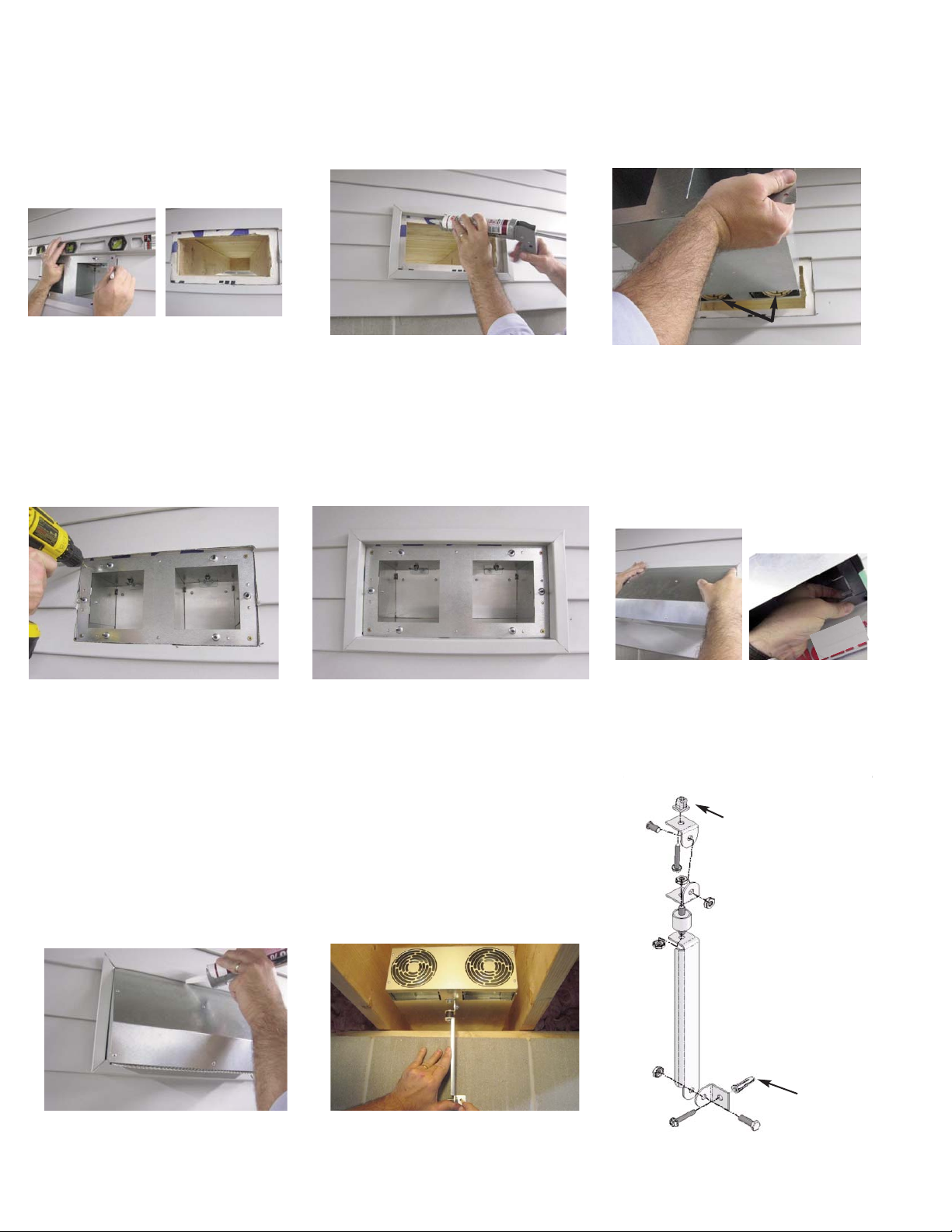
4. Remove fans if necessary and insert XCHANGERTMhousing through exterior wall opening with fan openings facing down,
(See Diagram G). For vinyl or other types of lap siding, level X
CHANGER
TM
and trace outer flange on XCHANGERTMhousing and
trim siding back enough to install J channel or appropriate flashing, (See Diagram E).
5. Place a bead of caulk on X
CHANGER
6. Remove fans if necessary and insert X
TM
mounting flange or building sheathing before inserting housing, (See Diagram F).
CHANGER
TM
housing through exterior wall opening with fan openings facing down, (See Diagram G).
DIAGRAM E
LEVEL XCHANGER AND TRACE FLANGE. TRIM
SIDING BACK SO XCHANGER FLANGE CAN BE
MOUNTED FLUSH TO EXTERIOR SHEATHING.
DIAGRAM F
PLACE A BEAD OF CAULK ON XCHANGER
MOUNTING FLANGE OR BUILDING SHEATHING
BEFORE INSERTING HOUSING.
INSERT XCHANGER HOUSING THROUGH WALL.
FAN OPENINGS MUST FACE DOWN.
DIAGRAM G
FAN OPENINGS FACING DOWN
7. Level housing and secure to wall using (4) screws, (See Diagram H). Install J channel or appropriate flashing around X
mounting flange. Do not cover up mounting flange or hood may not fit in J channel, (See Diagram I).
8. Hook X2D hood on housing top flange, center and bend tab over on each side on bottom of hood, (See Diagram J).
DIAGRAM H
DIAGRAM I
DIAGRAM J
CHANGER
TM
LEVEL HOUSING AND SECURE TO WALL USING
(4) SCREWS.
INSTALL J CHANNEL OR APPROPRIATE FLASHING
AROUND XCHANGER MOUNTING FLANGE.
9. Apply a bead of caulk around hood and siding, (See Diagram K).
10. Insert plastic nut into X
CHANGER
TM
base. Assemble mounting bracket as shown,
(See Diagram M). Attach assembled bracket to bottom of XCHANGERTM. Mark bracket
mounting location on wall with a slight upward pitch in rear of XCHANGERTMand connect
to wall using provided wall anchor, (See Diagram L).
DIAGRAM K
APPLY A BEAD OF CAULK AROUND HOOD AND
SIDING..
ATTACH MOUNTING BRACKET TO BOTTOM OF
XCHANGER. INSTALL BRACKET SO XCHANGER HAS A SLIGHT UPWARD PITCH IN REAR.
DIAGRAM L
HOOK X2D HOOD ON HOUSING TOP FLANGE,
CENTER AND BEND TAB OVER ON EACH SIDE
ON BOTTOM OF HOOD.
DIAGRAM M
INSERT PLASTIC NUT
INTO XCHANGER BASE
WALL
ANCHOR
ASSEMBLE XCHANGER MOUNTING BRACKET.
5
Page 7

11. The XCHANGERTMcomes with (2) air infiltration magnetic draft stops to block incoming air during seasons or periods when the
X
CHANGER
TM
is not in use if desired. Place magnet(s) over XCHANGERTMfan opening(s) when fan is not in use to block air infiltra-
tion. Place magnet(s) on side of XCHANGERTMcabinet so they are not lost if not in use to block fan openings, (See Diagram N).
12. WARNING: Unplug fans from dehumidistat control when changing fan direction to prevent damage or injury. Insert fans in desired
direction for either exhaust or intake. See arrow on bottom of fan cartridge or side of fan shroud for air flow direction. Once
installed confirm the air is being exhausted or supplied depending upon application, (See Diagram O).
13. Insulate around X
CHANGER
TM
housing, (See Diagram P).
XCHANGER DEHUMIDISTAT CONTROL MODULE INSTALLATION & OPERATION
DIAGRAM N
PLACE MAGNETIC DRAFT STOPS OVER XCHANGER
FAN OPENING(S) WHEN FAN IS NOT IN USE TO
BLOCK AIR INFILTRATION IF DESIRED. PLACE ON
SIDE OF CABINET IF NOT IN USE SO THEY ARE NOT
LOST.
WARNING: UNPLUG FANS WHEN CHANGING
DIRECTION. SEE ARROW ON BOTTOM OF FAN
CARTRIDGE OR SIDE OF FAN SHROUD FOR
AIR FLOW DIRECTION.
DIAGRAM O
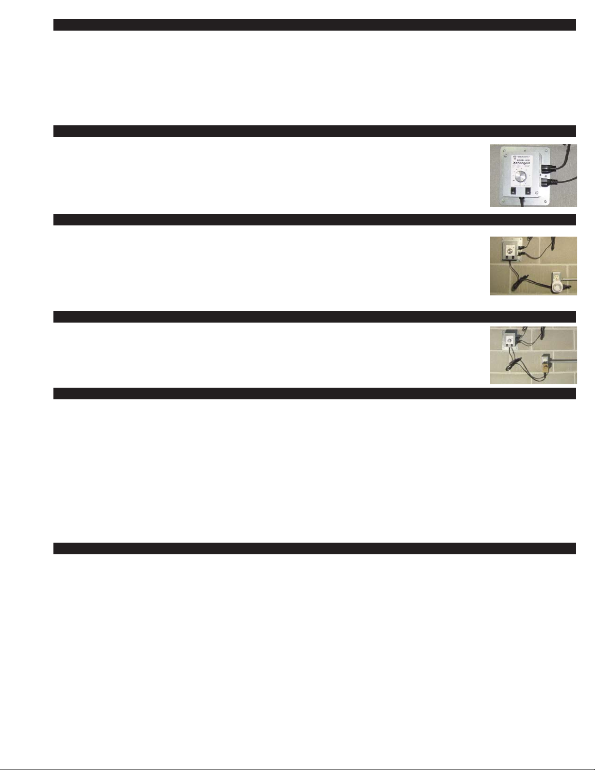
XCHANGER DEHUMIDISTAT CONTROL MODULE INSTALLATION & OPERATION
Install XCHANGERTMdehumidistat control module on wall with provided screws and
wall anchors and plug XCHANGERTMfans into side outlets.
IMPORTANT: Do not plug other devices into dehumidistat control or damage may result.
Once fans are installed in X
The X
CHANGER
TM
control module includes an adjustable dehumidistat control which
CHANGER
TM
, plug dehumidistat control into standard outlet.
activates the fan(s) if the relative humidity rises above the selected set-point. It is generally recommended to maintain a Relative Humidity (RH) below 60% to inhibit mold
growth. The dehumidistat can be turned fully clockwise to the ‘on’ position for constant
fan(s) operation or it can be turned fully counter-clockwise to ‘off’ during seasons or
times when it is not desired for the X
CHANGER
TM
fan(s) to run. Each XCHANGERTMfan
is independently controlled by its own on/off switch. Turn switch(s) off during seasons
or applications where it is not desired to run that fan, (See Diagram Q).
DIAGRAM P
INSULATE AROUND XCHANGER HOUSING.
DIAGRAM Q
IMPORTANT:
ONLY PLUG
FAN ON/OFF
SWITCHES
SCREW DEHUMIDISTAT CONTROL TO WALL AND
PLUG FANS INTO SIDE OUTLETS.
XCHANGER FANS
INTO CONTROL!
120 VAC
50/60 Hz
NEUTRAL BLACK
HOT BLACK
XCHANGER LADDER DIAGRAM
XCHANGER FANS
SWITCHED OUTLETS
RED
WHITE
BLACK
DE-HUMIDISTAT
CHANGE CONTROL BOX
RX
RED
BLUE
6
RED
FAN SWITCH 1
RED
FAN SWITCH 2
8050022
Page 8

MAINTENANCE
The XCHANGERTMhood screen must be inspected every 3 to 6 months. Remove any
foreign material such as leaves, lint, cottonwood or other items. Remove screen to
clean if necessary, (See Diagram R).
INSERT HOOD
SCREEN IN HOOD
GUIDES.
DIAGRAM R
HOW HOW TO OBTAIN SERVICE ASSISTANCE
1. If you have any questions about your XCHANGERTMor if it requires adjustment, repair or routine maintenance, we suggest
that you contact your installer, contractor or service agency.
2. If you require technical information contact Tjernlund Products, Inc. at 1-800-255-4208 or email us at fanmail@tjfans.com.
When contacting Tjernlund Products, Inc., please have the following information available:
1. Model number and date code of the X
CHANGER
TM
2. Name and address of installer and service agency
3. Date of original installation and dates any service work was performed
4. Details of the problem
LIMITED PARTS WARRANTY AND CLAIM PROCEDURE
Tjernlund Products, Inc. warrants the components of the XCHANGERTMfor one year from date of installation. This warranty covers
defects in material and workmanship. This warranty does not cover normal maintenance, transportation or installation charges for
replacement parts or any other service calls or repairs. This warranty DOES NOT cover the complete X
CHANGER
TM
if it is operative,
except for the defective part.
Tjernlund Products, Inc. will issue credit or provide a free part to replace one that becomes defective during the one year warranty
period. All receipts should include the date code of the XCHANGERTMto ensure that the defective component corresponds with the
complete unit. This will help prevent possible credit refusal.
1.) Follow troubleshooting guide to determine defective component. If unable to determine faulty component, contact your
Tjernlund distributor, Tjernlund Products Technical Customer Service Department at 1-800-255-4208 for troubleshooting
assistance or email us at fanmail@tjfans.com.
2.) After the faulty component is determined, return it to your Tjernlund distributor for replacement. Please include X
CHANGER
date code component was taken from. Credit or replacement will only be issued to a Tjernlund distributor after the defective
part has been returned prepaid to Tjernlund.
WHAT IS NOT COVERED
Product installed contrary to our installation instructions
Product that has been altered, neglected or misused
Any freight charges related to the return of the defective part
Any labor charges related to evaluating and replacing the defective part
TJERNLUND LIMITED 1 YEAR WARRANTY
Tjernlund Products, Inc. warrants to the original purchaser of this product that the product will be free from defects due to faulty material or workmanship for a period of (1)
year from the date of original purchase or delivery to the original purchaser, whichever is earlier. Remedies under this warranty are limited to repairing or replacing, at our
option, any product which shall, within the above stated warranty period, be returned to Tjernlund Products, Inc. at the address listed below, postage prepaid. THERE ARE
NO WARRANTIES WHICH EXTEND BEYOND THE DESCRIPTION ON THE FACE HEREOF, AND TJERNLUND PRODUCTS, INC. EXPRESSLY DISCLAIMS LIABILITY
FOR INCIDENTAL OR CONSEQUENTIAL DAMAGES ARISING FROM THE USE OF THIS PRODUCT. THIS WARRANTY IS IN LIEU OF ALL OTHER EXPRESS WARRANTIES AND NO AGENT IS AUTHORIZED TO ASSUME FOR US ANY LIABILITY ADDITIONAL TO THOSE SET FORTH IN THIS LIMITED WARRANTY. IMPLIED WARRANTIES ARE LIMITED TO THE STATED DURATION OF THIS LIMITED WARRANTY. Some states do not allow limitation on how long an implied warranty lasts, so that
limitation may not apply to you. In addition, some states do not allow the exclusion or limitation of incidental or consequential damages, so that above limitation or exclusion may not apply to you. This warranty gives you specific legal rights and you may also have other rights which may vary from state to state. Send all inquiries regarding warranty work to Tjernlund Products, Inc. 1601 9th Street, White Bear Lake, MN 55110-6794. Phone (651) 426-2993 • (800) 255-4208 • Fax (651) 426-9547 • Email
fanmail@tjfans.com.
TM
XCHANGER PARTS AND ACCESSORIES
REPLACEMENT PARTS
XCHANGERTMFan Assembly 950-8350
XCHANGERTMDehumidistat 950-8351
XCHANGERTMX2D Hood Screen 950-8352
X
CHANGER
TM
X2D Hood with Screen 950-8353
XCHANGERTMMagnetic Draft Stops (2) 950-8354
ACCESSORIES
6” Duct Take-Off Kit DT2-6
Plug-In Speed Control SCP
7
 Loading...