

Page 1
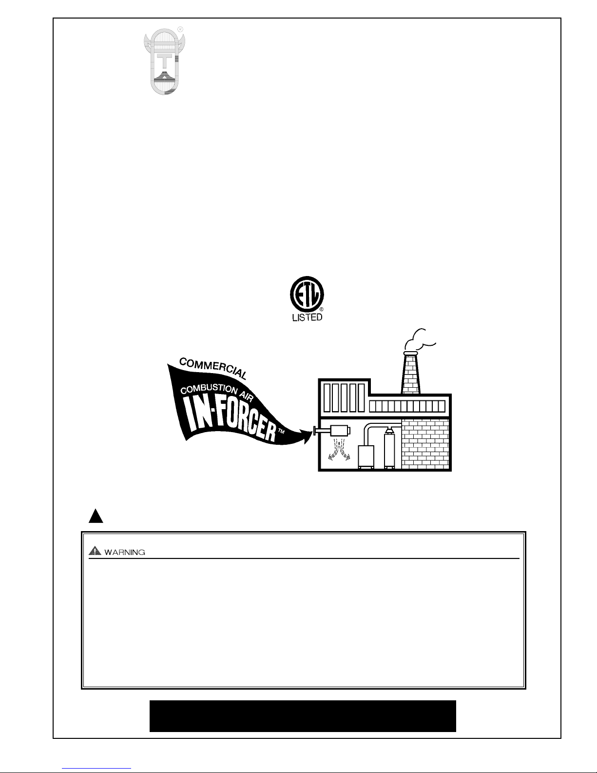
COMMERCIAL COMBUSTION AIR
IN-FORCER
TM
MODELS
PAI-3 PAI-4 PAI-5
PAI-6 PAI-7
Copyright © 2001, Tjernlund Products, Inc. All rights reserved. P/N 8504036
REV. A 05/01
OWNER INSTRUCTIONS, DO NOT DESTROY
Recognize this symbol as an indication of important Safety Information!
THESE INSTRUCTIONS ARE INTENDED AS AN AID TO QUALIFIED, LICENSED
SERVICE PERSONNEL FOR PROPER INSTALLATION, ADJUSTMENT AND
OPERATION OF THIS UNIT. READ THESE INSTRUCTIONS THOROUGHLY
BEFORE ATTEMPTING INSTALLATION OR OPERATION. FAILURE TO FOLLOW
THESE INSTRUCTIONS MAY RESULT IN IMPROPER INSTALLATION, ADJUSTMENT, SERVICE OR MAINTENANCE POSSIBLY RESULTING IN FIRE, ELECTRICAL SHOCK, CARBON MONOXIDE POISONING, EXPLOSION, OR PERSONAL
INJURY OR PROPERTY DAMAGE.
!
PLEASE READ CAREFULLY AND KEEP ON JOB
SITE FOR FUTURE REFERENCE.
TJERNLUND PRODUCTS, INC.
1601 Ninth Street • White Bear Lake, MN 55110-6794
PHONE (800) 255-4208 • (651) 426-2993 • FAX (651) 426-9547
Visit our web site • www.tjernlund.com
Page 2
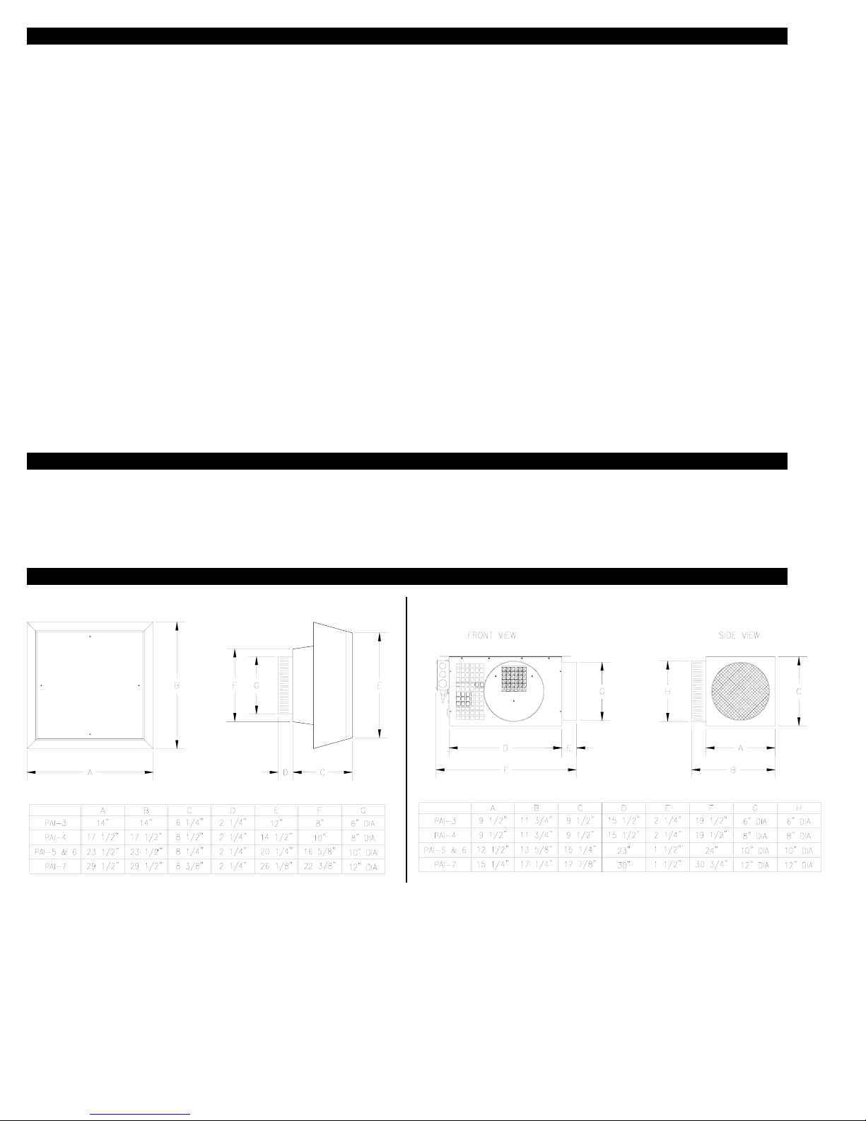
TABLE OF CONTENTS
Description and Specifications ....................................................................................................................................1, 2
Installation Restrictions....................................................................................................................................................2
Cautions ..........................................................................................................................................................................2
IN-FORCER Selection Table ...........................................................................................................................................3
Safety Inspection of a Previously Used Appliance..........................................................................................................4
Commercial IN-FORCER Terminology ............................................................................................................................4
Intake Hood Locations - Wall or Roof Mount ..................................................................................................................5
Installation
Tools Required ...............................................................................................................................................................5
Installation of Intake Hood
Roof Mount of Intake Hood...........................................................................................................................5, 6
Wall Mount of Intake Hood................................................................................................................................6
IN-FORCER Mounting.....................................................................................................................................................7
Electrical Wiring
IN-FORCER Internal Wiring Schematic ............................................................................................................8
IN-FORCER Fan Prover and Motor Isolation Relay Diagram ..........................................................................8
24 VAC Wiring with Single Appliance ...............................................................................................................9
115 VAC Wiring with Single Appliance..............................................................................................................9
Oil Wiring with Single Appliance .....................................................................................................................10
Oil & Gas Wiring with up to Four Appliances & the Optional MAC-4 .............................................................10
System Operation Check Out........................................................................................................................................11
Maintenance ..................................................................................................................................................................11
Trouble Shooting .........................................................................................................................................11, 12, 13, 14
How To Obtain Service, Warranty & Replacement Parts........................................................................................14, 15
IN-FORCER Fan Curves...............................................................................................................................................15
IN-FORCER
TM
is a trademark of Tjernlund Products, Inc. for IN-FORCER air intakes.
DESCRIPTION
The IN-FORCER combustion air intake systems are designed and Listed for use with atmospheric or induced combustion gas and oil
heating equipment. The IN-FORCER functions as the source of combustion air, eliminating the need for louvered openings. The
IN-FORCER assures intake air is supplied by monitoring the air flow with a Fan Proving Switch. The main burner will be interrupted if
a malfunction occurs.
ICATIONS
DIMENSIONS & SPECIFICATIONS
PAI-3 Motor: 115/1/60, 3000 RPM, 95 watts, 1.26 FLA, Thermal Protection
PAI-4 Motor: 115/1/60, 3300 RPM, 166 watts, 1.51 FLA, Thermal Protection
PAI-5 Motor: 115/1/60, 1725 RPM, 1/4 HP, 5.4 Amps, Thermal Protection
PAI-6 Motor: 115/1/60, 1725 RPM, 1/3 HP, 5.8 Amps, Thermal Protection
PAI-7 Motor: 115/208/230/1/60, 1725 RPM, 1 HP, 12.6/6.3/6.2 Amps, Thermal Protection
24-Volt Control Circuits: All models require a relay to activate the IN-FORCER motor. Tjernlund P/N 950-1040 is applicable to all
models except the PAI-7. The PAI-7 requires P/N 950-1016.
115 Volt Control Circuits: IN-FORCERS may be directly wired into a heating appliance control circuit as long as the contacts of the
circuit can handle the additional load of the IN-FORCER motor. For installations that require a relay, Tjernlund P/N 950-0480 is applicable to all models except the PAI-7. The PAI-7 requires P/N 950-0483.
1
INTAKE HOOD DIMENSIONS IN-FORCER POWERED INTAKE DIMENSIONS
Page 3
Fan Proving Switch: Do not exceed 3 FLA or 1/10 HP through proving switch contacts. You may add one of relays listed on bottom
of page 1 to isolate the proving switch contacts if the load being switched exceeds the maximum rating.
High Limit: Manual reset N/C contacts, open at 160° +
8° F, 14 FLA @120 VAC. The high limit switch will deactivate the IN-FORCER
if temperature adjacent to high limit reaches the set point. Reset button is located on inside of cabinet on electrical box side of IN-FORCER.
GENERAL INFORMATION
1. These units have been factory tested and rated in accordance with AMCA Standard 210, test code for air moving devices.
2. Each IN-FORCER is electrically factory line tested before shipment.
3. After opening carton, inspect thoroughly for hidden damage. Fan wheel should rotate freely. If any damage is found, notify freight
carrier and your distributor immediately and file a concealed damage claim.
INSTALLATION RESTRICTIONS
1. Observe proper location of Intake Hood as described on page 5.
2. If IN-FORCER outlet is mounted lower than seven feet above the utility room floor, a minimum 2 foot section of pipe must be
installed on the discharge side of the IN-FORCER to prevent accidental contact with operating blower wheel.
Improper installation, adjustment, alterations, service or maintenance can cause injury or property damage. Refer to this manual. For
assistance or additional information consult a qualified installer, service agency or the equipment supplier.
CAUTIONS
1. Failure to install, maintain and/or operate the IN-FORCER in accordance with manufacturer’s instructions may result in conditions
that can produce bodily injury and property damage.
NOTE: Cold climate installations must adhere to warning #4 and #7.
2. The IN-FORCER must be installed by a qualified installer (an individual properly licensed and/or trained) in accordance with all
local codes or in their absence, in accordance with the appropriate National Fire Protection Association #31, #54, #211 and the
National Electric Code.
3. The IN-FORCER motor shaft must be mounted horizontally, with discharge also facing horizontally to prevent motor bearing wear
and ensure proper operation of the Fan Proving Switch.
4. Do not discharge onto water pipes or other equipment which may be affected by temperature extremes.
5. Disconnect power supply when making wire connections and servicing the IN-FORCER. Failure to do so may result in personal
injury and/or equipment damage.
6. Make certain the power source is adequate for the IN-FORCER requirements. Do not add the IN-FORCER to a circuit where the
total electrical load is unknown.
7. To prevent potentially damaging low mechanical room temperatures, it is recommended that a low temperature limit be installed.
8. WARNING: To reduce the risk of fire or electric shock, do not use this fan with any solid state speed control device.
9. WARNING: To reduce the risk of electric shock and injury to persons, do not use in a window.
10. WARNING: To reduce the risk of fire, electric shock, or injury to persons, observe the following:
a.) Installation work and electrical wiring must be done by qualified person(s) in accordance with all applicable codes and
standards, including fire-rated construction.
b.) Sufficient air is needed for proper combustion and exhausting of gases through the flue (chimney) of fuel burning equipment
to prevent back drafting. Follow the heating equipment manufacturer’s guideline and safety standards such as those
published by the National Fire Protection Association (NFPA), and the American Society for Heating, Refrigeration, and Air
Conditioning Engineers (ASHRAE), and the local code authorities.
c.) When cutting or drilling into wall or ceiling, do not damage electrical wiring or other hidden utilities.
The IN-FORCER CFM outputs will assure that adequate combustion air is supplied if the appliance is functioning properly. However,
in the event that there is an appliance malfunction, such as a cracked heat exchanger or clogged flue, there is no guarantee that additional combustion air will eliminate carbon monoxide spillage into the equipment room.
2
Page 4
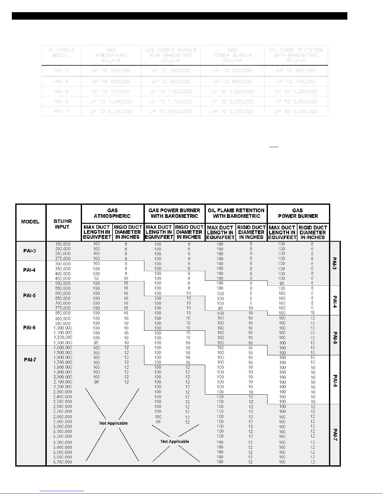
IN-FORCER APPLICATION AND SELECTION TABLE
Verify that the total BTU/hr input of the heating appliance(s) falls within the range specified below. Check maximum duct length and
appropriate duct diameter with the IN-FORCER Selection Table below.
ECIFIN-FORCER SELECTION TABLE
IN-FORCER SELECTION TABLE
MAX. DUCT LENGTH IN EQUIV. FEET indicates how much duct may be used at the given diameter based on the four types of heating equipment.
All duct before and after the IN-FORCER must be added. To calculate equivalent duct length, add the straight duct plus 10’ for every 90
0
elbow and 5’
for each 450elbow. Values in the chart assume rigid metal duct. Consult flex duct manufacturer for de-rating percentage if using flex duct. The resistance for any combination of ducts and diffusers cannot exceed the maximum equivalent duct length shown in selection table.
If interlocking IN-FORCER with more than one appliance of the same type, add the BTU/HR. input of each appliance to determine IN-FORCER model
and maximum equivalent duct length and diameter. If interlocking IN-FORCER with different types of equipment consult Tjernlund Technical Customer
Service @ 1-800-255-4208 for further information.
3
Page 5

SAFETY INSPECTION OF A PREVIOUSLY USED OIL APPLIANCE
S
(Perform prior to IN-FORCER installation)
The following procedure is intended as a guide to aid in determining that an appliance is properly installed and is in safe condition for
continuing use. This procedure is based on central furnace and boiler installations and it should be recognized that generalized procedures cannot anticipate all situations. Accordingly, in some cases deviation from this procedure may be necessary to determine
safe operation of the equipment.
A. This procedure should be performed prior to any attempt at modifications of the appliance or installation of the IN-FORCER.
B. If it is determined there is a condition which could result in unsafe operation, the appliance should be shut off and the owner
advised of the unsafe condition.
The following steps should be followed in making the safety inspection:
1. Visually inspect the venting system and determine there is no blockage or restriction, leakage, corrosion or other deficiencies
which could cause an unsafe condition.
2. Inspect burner and primary control for proper operation.
3. Applicable only to furnaces:
Inspect heat exchanger for cracks, openings or excessive corrosion. Check both the limit control
and fan control for proper operation.
4. Applicable only to boilers:
Inspect for evidence of water or combustion product leaks. Determine that the water pumps are in
operating condition. Test low water cutoffs, automatic feed controls, pressure and temperature limit controls and relief valves in
accordance with the manufacturer's recommendations to determine that they are in operating order.
SAFETY INSPECTION OF A PREVIOUSLY USED GAS APPLIANCE
(Perform prior to IN-FORCER installation)
The following procedure is intended as a guide to aid in determining that an appliance is properly installed and is in safe condition for
continuing use. This procedure is based on central furnace and boiler installations and it should be recognized that generalized procedures cannot anticipate all situations. Accordingly, in some cases deviation from this procedure may be necessary to determine
safe operation of the equipment.
A. This procedure should be performed prior to any attempt at modifications of the appliance or installation of the IN-FORCER.
B. If it is determined there is a condition which could result in unsafe operation, the appliance should be shut off and the owner
advised of the unsafe condition.
The following steps should be followed in making the safety inspection:
1. Conduct a gas leakage test of the appliance piping and control system downstream of the shutoff valve in the supply line to the
appliance.
2. Visually inspect the venting system and determine there is no blockage or restriction, leakage, corrosion and other deficiencies
which could cause an unsafe condition.
3. Shut off all gas to the appliance(s).
4. Inspect burners and crossovers for blockage and corrosion.
5. Applicable only to furnaces:
Inspect heat exchanger for cracks, openings or excessive corrosion. Check both the limit control and
fan control for proper operation.
6. Applicable only to boilers: Inspect for evidence of water or combustion product leaks. Determine that the water pumps are in
operating condition. Test low water cutoffs, automatic feed controls, pressure and temperature limit controls and relief valves in
accordance with the manufacturer's recommendations to determine that they are in operating order.
* Excerpts from the National Fuel Gas Code (ANSI Z223.1/NFPA #54), Appendix H.
IN-FORCER TERMINOLOGY
4
Page 6

INTAKE HOOD LOCATIONS - WALL MOUNT OR ROOF MOUNT
The IN-FORCER has been Listed in accordance with the 1990 BOCA National
Mechanical Code, Section M-306.1 and
M-306.1.1 as follows.
M-306.1 LOCATION:
Outside air exhaust and intake openings shall
be located a minimum of 10 feet (3048mm)
from lot lines or buildings on the same lot.
When openings front on a street or public way,
the distance shall be measured to the centerline of the street or public way.
M-306.1.1 INTAKE OPENINGS:
Outside air intake openings shall be located a
minimum of 10 feet (3048mm) from any hazard
or noxious contaminant such as vents, chimneys, plumbing vents, streets, alleys, parking
lots and loading docks. When a source contaminant is located within 10 feet
(3048mm) of an
intake opening, such opening shall be located a
minimum of 2 feet (610mm) below the contaminant source.
IN ADDITION TO THESE CODES THE
MANUFACTURER RECOMMENDS THAT:
The Intake Hood should be a minimum of 1 foot above grade or anticipated snow line.
INSTALLATION (TOOLS REQUIRED)
•Reciprocating saw •1/4”, 5/16”, 3/8” nut runner or socket •Wire cutter/stripper
•Drill and 1/4” bit •Blade screwdriver •Masonry chisel
INSTALLATION OF INTAKE HOOD
Note: Before cutting opening through wall or roof, figure layout of pipe runs. Consult selection table on page 3 and Intake Hood loca-
tion above.
The Intake Hood is designed so relatively large amounts of outdoor air can be pulled in through a small wall or roof opening. If properly installed, rain and snow will not be pulled in with the outdoor air. Systems installed without the PAI-Series Intake Hood may be
susceptible to the entry of rain or snow and CFM values can not be guaranteed.
The Intake Hood may be primed and painted to blend in with the building exterior.
The Intake Hood can be mounted on an outside wall or roof.
ROOF MOUNT INSTALLATION OF INTAKE HOOD
1. Attach take-off collar to the Intake Hood Base by bending over the tabs of the collar. Screw galvanized pipe to take-off collar on
Intake Hood Hood base.
2. Verify that roof penetration will not come in contact with concealed wiring or plumbing. Cut a circular hole through the roof.
(PAI-3 Rough-In: 6 1/2”, PAI-4 Rough-In: 8 1/2” , PAI-5/6 Rough-In: 10 1/2”, PAI-7 Rough-In: 12 1/2”)
3. Install 4 pieces of plumber’s strap from the Intake Hood Base to the pipe. Use the provided 1/4” bolts, washers, and nuts to attach
the straps to the hood. Use 2 sheet metal screws per strap to attach the straps to the pipe, (See Diagram A).
4. Secure Intake Hood cover to base with #8 x 3/8” sheet metal screws, PAI-3/4 (4), PAI-5/6 (8), PAI-7 (20), (See Diagram A).
5. Install roof flashing and storm collar. Clamp storm collar around galvanized pipe penetrating through to the interior. Intake Hood
should be at least 2 feet above the roof.
6. Install Intake Hood backing plate on ceiling if desired with #10 x 1 1/4” screws provided, PAI-3/4 (4), PAI-5/6/7 (8).
5
On wall installations, if possible, terminate the IN-FORCER on a wall that does not face the direction of prevailing winds. This will diminish the possibility of wind infiltration.
Page 7

WALL MOUNT INSTALLATION OF INTAKE HOOD
1. Attach take-off collar to Intake Hood base by bending over the tabs of the collar.
2. Verify that wall penetration will not come in contact with concealed wiring or plumbing. Cut a circular or square opening through
the wall. (PAI-3 Rough-In: 6 1/2”, PAI-4 Rough-In: 8 1/2” , PAI-5/6 Rough-In: 10 1/2”, PAI-7 Rough-In: 12 1/2”)
3. Secure section of galvanized pipe to Intake Hood collar with sheet metal screws.
4. Insert Intake Hood with pipe attached through opening and mark location of mounting holes, PAI-3/4 (4), PAI-5/6/7 (8), (See Diag. B).
Drill 1/4” diameter holes at marked locations, insert plastic wall anchors (for masonry wall).
5. Apply a bead of caulk around perimeter of Intake Hood Base, (See Diagram C). Insert Intake Hood through opening, align
mounting holes and secure to wall with #10 x 1 1/4” screws provided, PAI-3/4 (4), PAI-5/6/7 (8).
6. Secure Intake Hood Cover using #8 x 3/8” sheet metal screws, PAI-3/4 (4), PAI-5/6 (8), PAI-7 (20), (See Diagram D).
7. Apply a bead of caulk to the rear flange of the Rain Shield and position Rain Shield on the Intake Hood making sure it is adjusted
flush against the wall. Use adjustment slot and pierce through hood dimples with (2) #8 x 3/8” sheet metal screws, (See Diagram E).
INS
MODEL PAI-7 ONLY
When installing PAI-7 Hood apply Rain Shield with caulking over middle adjustment slot of rain shield. Install leak proofing tab
between Rain Shield and Intake Hood, (See Diagram D).
8. Install Intake Hood backing plate on interior wall with provided #10 x 1 1/4” screws and wall anchors, PAI-3/4 (4), PAI-5/6/7 (8).
6
DIAGRAM D
DIAGRAM B
DIAGRAM E
DIAGRAM C
DIAGRAM A
Page 8

IN-FORCER MOUNTING
INSTALLER NOTE
1. For easier wiring and servicing maintain 18” clearance from the rear and control sides and 12” from the top of the IN-FORCER.
2. For easier electrical interlock plan for sufficient duct so that the IN-FORCER can be suspended adjacent to the heating equipment
that it serves.
INSTALLER CAUTION
1. Do not directly discharge onto water piping or objects that may be affected by temperature extremes.
2. In areas with low temperature extremes it is advisable to insulate ducts or use insulated duct.
3. Do not exceed equivalent duct lengths listed in IN-FORCER Selection Table on Page 3.
The IN-FORCER is designed to be hung from an overhead support. The discharge must remain horizontal.
MODELS PAI-3 & PAI-4 (DIAGRAM F)
Verify that overhead support has sufficient strength to hold weight of IN-FORCER. Bend mounting support flanges to the angle best
suited to the specific installation. Use perforated strap (installer supplied) and the provided 1/4”-20 x 3/4” hex head bolts and kep nuts
to secure strap to the holes in the mounting flanges, (See Diagram F).
MODELS PAI-5, PAI-6, PAI-7 (DIAGRAM G)
Verify that overhead support has sufficient strength to hold weight of IN-FORCER. Suspend from included eyebolts and chain. The
eyebolts may be secured to either the top or bottom of the IN-FORCER casing. Attaching the eyebolts to the bottom allows the
IN-FORCER inlet to be positioned to the opposite side, giving the option of a right hand or left-hand inlet pipe connection. Secure eye
bolt to IN-FORCER with nuts and washer as shown. On bottom of cabinet install 1/4”-20 x 3/4” hex head bolts, washers and nuts,
(See Diagram G).
2. Connect crimped end of intake duct to the IN-FORCER inlet collar with sheet
metal screws. Tape connection to inlet collar and all joints of intake duct to
prevent the entry of indoor air.
3. The discharge should terminate no closer than 3 feet from a barometric draft
control or intake grille of an appliance. If this is not possible terminate on sides
or opposite side of appliance intake. Never terminate within 3 feet from the front
or intake side of appliance. Discharge duct should also terminate a minimum of
18 inches above floor or other obstructions if perpendicular to them, (See Diag. H).
These clearances are necessary to prevent pilot outages and ensure proper draft
control operation.
7
DIAGRAM H
DIAGRAM F
DIAGRAM G
Page 9

ELECTRICAL
All wiring from the IN-FORCER to the appliance must be appropriate Class 1 wiring as follows: installed in rigid metal conduit, intermediate conduit, rigid non-metallic conduit, electrical metallic tubing, Type MI Cable, Type MC Cable or be otherwise suitably protected from physical damage.
The IN-FORCER has a high temperature limit switch to deactivate the system in the event of a mechanical room fire. It also has a fan
proving switch to prove operation prior to burner ignition.
8
IN-FORCER WIRED WITH FAN PROVER AND MOTOR ISOLATION RELAYS
IN-FORCER INTERNAL WIRING SCHEMATIC
ACCESSORY RELAYS FOR ISOLATION
24/115 Volt 1/2 H.P. Relay 950-1040
24/115 Volt 1 1/2 H.P. Relay 950-1016
115/115 Volt 1/2 H.P. Relay 950-0480
115/115 Volt 1 1/2 H.P. Relay 950-0483
Page 10

9
IN-FORCER CONNECTED TO A SINGLE 24 VAC APPLIANCE WITH INTERMITTENT IGNITION
IN-FORCER CONNECTED TO A SINGLE 115 VAC APPLIANCE
IN-FORCER CONNECTED TO A SINGLE 24 VAC APPLIANCE WITH STANDING PILOT
COMPONENTS NEEDED:
(1) COMBUSTION AIR IN-FORCER
(1) 24/115V RELAY
USE 950-1040 FOR MODELS PAI-3/4/5/6
USE 950-1016 FOR MODEL PAI-7
COMPONENTS NEEDED:
(1) COMBUSTION AIR IN-FORCER
(1) 24/115V RELAY
USE 950-1040 FOR MODELS PAI-3/4/5/6
USE 950-1016 FOR MODEL PAI-7
Page 11

10
IN-FORCER CONNECTED WITH UP TO 4 OIL APPLIANCES & THE OPTIONAL MAC-4
IN-FORCER CONNECTED WITH UP TO 4 24V GAS APPLIANCES & THE OPTIONAL MAC-4
IN-FORCER CONNECTED WITH AN R8184G OIL PRIMARY CONTROL
Page 12

SYSTEM OPERATION CHECK-OUT
1. Adjust thermostat or appliance to call for heat.
2. Verify that IN-FORCER operates first, prior to burner ignition.
Allow heating equipment and IN-FORCER to operate continuously while performing steps 3-6.
3. Close all interior doors, windows and openings of the mechanical room.
4. Turn on any equipment in the mechanical room that exhausts indoor air during its operation.
5. Allow IN-FORCER and equipment to operate for at least five minutes.
6. Place a smoke source a couple of inches from draft hood or draft diverter and verify that appliance is pulling in smoke, (See Diagram I).
If appliance is venting properly, smoke source will be pulled in. If smoke is not pulled in, a blocked flue or negative pressure exists. If
problem can’t be determined contact Tjernlund for further assistance.
MAINTENANCE
Disconnect power supply to the IN-FORCER when servicing. The IN-FORCER should be inspected every 6 months. Points of
inspection are:
Motor:
For optimum performance, oil motor annually with SAE 10 oil (Model PAI-3 has a permanently lubricated motor). Motor assembly may
be partially slid out of housing by removing screws located on the center of the top and bottom panels on the models PAI-3/4. The
models PAI-5/6/7 have two screws on the front panel under the outlet collar and four 1/4” motor mount bolts if motor removal is necessary.
Wheel:
Wheel must be clean of any foreign material such as leaves, lint or other items. Remove all foreign material from
blower assembly before operation, (See Diagram J).
Intake Hood:
Intake Hood screen should be clear of any foreign material such as leaves, lint or other items. Remove Intake
Hood cover and check perforated air inlet screens for foreign material. Remove all foreign material from Intake Hood screens before
operation, (See Diagram K).
Aluminum Mesh Prefilter:
The prefilter and interior of the housing should be cleaned annually, or as needed in dirty atmospheres. The filter is accessed by
removing the rear access door on the models PAI-3/4, or by removing the filter rack panel on the models PAI- 5/6/7.
TROUBLE SHOOTING
The following guide is intended to be used if a problem occurs during the use of the IN-FORCER. At several steps throughout the
guide you will come in close contact with 115 Volts. Extreme caution must be exercised to prevent injury. If you are unable to
determine the defective part with the use of this guide, call your Tjernlund distributor or Tjernlund Products direct at 1-800-255-4208
for further assistance.
11
DIAGRAM I
DIAGRAM K
DIAGRAM J
Page 13

12
Wiring not correct
SYMPTOM 1: IN-FORCER RUNS BUT BURNER WILL NOT FIRE (24 VAC CONTROL CIRCUIT)
IN-FORCER WIRED WITH A 24 VAC CONTROL CIRCUIT
Step 2.
With the appliance calling for heat and the
IN-FORCER running, check for voltage
across YELLOW of the Fan Prover and
ORANGE “coil common” of the 24 VAC relay
Result: Measure 24 volts.
Step 1.
Recheck all wiring per the installation instructions.
Step 3. (Wired with gas valve)
With the appliance calling for
heat and the IN-FORCER running, check for 24 volts across
the TH(HOT) and TR(COM) terminals on appliance gas valve.
Result: Measure 24 volts.
Step 3. (Wired with single
zone gas or oil furnace
terminal strip/fan center)
With the thermostat calling for
heat and the IN-FORCER running, check for 24 volts across
the W and C(COM) terminals
on appliance terminal strip/fan
center.
Result: Measure 24 volts.
Step 4.
Contact appliance manufacturer for further assistance.
Yes
Solution: Rewire the IN-FORCER per the
installation instructions or contact Tjernlund
Products for further assistance.
No
obstruc-
tions
Solution:Replace
Fan Proving Switch.
PAI-3 950-0476
PAI-4 950-0474
PAI-5/6 950-0472
PAI-7 950-0471
Solution: Clean
intake screen of
clogged material.
Check for excessive
length or sharp
bends in discharge
or inlet vent pipe.
Verifiy fan prover
sensing tube is not
kinked and is properly connected.
No
No
Solution: Repeat steps 1-3 or contact
Tjernlund Products for further assistance.
Note: For further assistance contact Tjernlund Products, Inc.
Technical Customer Service Department at 1-800-255-4208.
No
Yes
Yes
Wiring not correct
No
SYMPTOM 2: IN-FORCER RUNS CONSTANTLY (24 VAC CONTROL CIRCUIT)
Step 2.
Remove the BLUE “coil hot” wire from relay while
IN-FORCER is running.
Result: IN-FORCER should shut off immediately.
Step 1.
Recheck all wiring per the installation instructions.
Step 3.
Measure for voltage on appliance thermostat or
aquastat when not calling for heat.
Result: Voltage not measured.
Yes
Yes
Step 4.
Contact appliance / thermostat manufacturer for
further assistance.
Yes voltage measured
Solution: Rewire the IN-FORCER per the
installation instructions or contact Tjernlund
Products for further assistance.
Solution: Replace the
IN-FORCER relay.
PAI-3/4/5/6 950-1040
PAI-7 950-1016
No voltage measured
Solution: Repeat step 1-3 or contact
Tjernlund Products for further assistance.
Note: For further assistance contact Tjernlund Products, Inc.
Technical Customer Service Department at 1-800-255-4208.
Activate appliance to call
for ignition. At this time
the IN-FORCER should
be running. Remove the
BLUE and YELLOW leads
on Fan Prover. Check for
continuity across the N.O.
and COM terminals of
the Fan Prover. Result:
Circuit should be closed.
Contact Tjernlund Products
for further assistance.
Yes
Page 14

13
No
Yes
SYMPTOM 3: IN-FORCER WILL NOT RUN ON CALL FOR HEAT (24 VAC CONTROL CIRCUIT)
Step 3.
With thermostat calling for heat, measure for 24 volts
across the ORANGE “coil common” and BLUE “ coil
hot” terminals on IN-FORCER relay.
Result: Measure 24V.
Yes
Yes
Solution: Contact
appliance / thermostat
manufacturer for further
assistance.
Note: For further assistance contact Tjernlund Products, Inc.
Technical Customer Service Department at 1-800-255-4208.
Step 4.
Caution: Disconnect the 115 volt power supply to the INFORCER before attempting the following procedure.
a) Remove the two BLACK leads from contact side of relay and
connect them together.
b) Reestablish the 115 volt power source to IN-FORCER.
Result: IN-FORCER should run constantly.
Measure voltage on thermostat
or aquastat when calling for
heat. Result: Measure 24 Volts.
Contact appliance manufacturer
for further assistance.
High Limit
will not reset
Replace high limit.
Part # 950-0477.
No
Solution: Replace IN-FORCER relay.
PAI-3/4/5/6 950-1040
PAI-7 950-1016
No
Solution: Replace IN-FORCER motor.
PAI-3 950-1020
PAI-4 950-1021
PAI-5 950-1022
PAI-6 950-0131
PAI-7 950-1017
Wiring not correct
SYMPTOM 1: IN-FORCER RUNS BUT BURNER DOES NOT FIRE (115 VAC CONTROL CIRCUIT)
II5 VAC CONTROL CIRCUIT
Step 1.
Recheck all wiring per the installation instructions.
Step 3.
Repeat step 1 & 2 or contact Tjernlund Products
for further assistance.
Wiring correct
Yes
Solution: Rewire the IN-FORCER per the
installation instructions or contact Tjernlund
Products for further assistance.
Note: For further assistance contact Tjernlund Products, Inc.
Technical Customer Service Department at 1-800-255-4208.
Step 2.
With the appliance calling for heat and the
IN-FORCER running, check for voltage
across YELLOW of the Fan Prover and L2.
Result: Measure 115 volts.
No
obstruc-
tions
Solution:Replace Fan
Proving Switch.
PAI-3 950-0476
PAI-4 950-0474
PAI-5/6 950-0472
PAI-7 950-0471
Solution: Clean
intake screen of
clogged material.
Check for excessive
length or sharp
bends in discharge
or inlet vent pipe.
Verifiy fan prover
sensing tube is not
kinked and is properly connected.
No
No
Contact Tjernlund Products
for further assistance.
Activate appliance to call
for ignition. At this time
the IN-FORCER should
be running. Remove the
BLUE and YELLOW leads
on Fan Prover. Check for
continuity across the N.O.
and COM terminals of
the Fan Prover. Result:
Circuit should be closed.
Wiring not correct
Step 1.
Recheck all wiring per the installation instructions.
Solution: Rewire the IN-FORCER per the installation instructions or contact Tjernlund Products
for further assistance.
Yes
Step 2.
CAUTION: With 115 volt circuits disconnected to IN-FORCER
remove the BLACK leads from high limit switch located on
inside of PAI cabinet. Check for continuity across high limit.
If circuit is closed put leads back on limit and proceed to Step 3.
If circuit is open push reset button on high limit switch and put
leads back on limit. Investigate possible cause for high limit cut
out. Reestablish 115 VAC power to IN-FORCER. Result: INFORCER motor should run upon a call for heat.
IN-FORCER will not run.
Page 15

HOW TO OBTAIN SERVICE ASSISTANCE
1. If you have any questions about your IN-FORCER or if it requires adjustment, repair or routine maintenance, we suggest that
you contact your installer, contractor or service agency.
2. If you require technical information contact Tjernlund Products, Inc. at 1-800-255-4208.
When contacting Tjernlund Products, Inc., please have the following information available:
1. Model name of the IN-FORCER as shown on the label attached to IN-FORCER.
2 Name and address of installer and any service agency who performed work on Power Venter.
3. Date of original installation and dates any service work was performed.
4. Details of the problem as you can best describe them.
LIMITED PARTS WARRANTY AND CLAIM PROCEDURE
Tjernlund Products, Inc. warrants the components of its products for one year from date of installation. This warranty covers defects
in material and workmanship. This warranty does not cover normal maintenance, transportation or installation charges for replacement parts or any other service calls or repairs. Products that are tampered with, damaged, or defective due to malfunctioning appliances are not covered under this warranty. This warranty DOES NOT cover the complete IN-FORCER if it is operative, except for the
defective part.
Tjernlund Products, Inc. will issue credit or provide a free part to replace one that becomes defective during the one year warranty period. If the part is over 18 months old, proof of date of the installation in the form of the contractor sales/installation receipt is necessary
to prove the unit has been in service for under one year. All receipts should include the date code of the IN-FORCER to ensure that the
defective component corresponds with the complete unit. This will help preclude possible credit refusal.
1.) Follow troubleshooting guide to determine defective component. If unable to determine faulty component, contact your Tjernlund
distributor or Tjernlund Products Technical Customer Service Department at 1-800-255-4208 for troubleshooting assistance.
2.) After the faulty component is determined, return it to your Tjernlund distributor for replacement. Please include IN-FORCER date
code component was taken from. If IN-FORCER date code is older than 18 months you will need to provide a copy of the original
installation receipt to your distributor. Credit or replacement will only be issued to a Tjernlund distributor after the defective part has
been returned prepaid to Tjernlund.
14
No
Step 2.
When appliance is calling for heat measure for 115 volts
across the Primary Control or contactor leads.
Result: 115 volts measured.
IN-FORCER will not run.
Yes
Step 4.
Contact Tjernlund Products for further assistance.
Yes
Solution: Contact appliance manufacturer for
further assistance.
No
Solution: Replace IN-FORCER motor.
PAI-3 950-1020
PAI-4 950-1021
PAI-5 950-1022
PAI-6 950-0131
PAI-7 950-1017
Note: For further assistance contact Tjernlund Products, Inc.
Technical Customer Service Department at 1-800-255-4208.
SYMPTOM 2: IN-FORCER WILL NOT RUN ON CALL FOR HEAT (115 VAC CONTROL CIRCUIT)
II5 VAC CONTROL CIRCUIT
High Limit
will not reset
Replace high limit.
Part # 950-0477.
Step 1.
CAUTION: With 115 volt circuits disconnected to IN-FORCER
remove the BLACK leads from high limit switch located on
inside of PAI cabinet. Check for continuity across high limit.
If circuit is closed put leads back on limit and proceed to Step 2.
If circuit is open push reset button on high limit switch and put
leads back on limit. Investigate possible cause for high limit cut
out. Reestablish 115 VAC power to IN-FORCER. Result: INFORCER motor should run upon a call for heat.
Step 3.
Connect the BLACK, WHITE and GREEN wires in the
IN-FORCER directly to a constant 115 volt power source.
Result: IN-FORCER runs constantly.
Page 16

REPLACEMENT PARTS COVERED BY WARRANTY
WHAT IS NOT COVERED
Product installed contrary to our installation instructions
Product that has been altered, neglected or misused
Product that has been wired incorrectly
Any freight charges related to the return of the defective part
Any labor charges related to evaluating and replacing the defective part
15
DESCRIPTION PART NUMBER
PAI-3 Motor 950-1020
PAI-4 Motor W/Wheel 950-1021
PAI-5 Motor 950-4020
PAI-6 Motor 950-0131
PAI-7 Motor 950-1017
PAI-3 Wheel 950-1011
PAI-4 Wheel 3/8” Bore 950-1012
PAI-5 Wheel 950-0486
PAI-6 Wheel 950-0487
PAI-7 Wheel 950-1015
PAI-3 Fan Prover 950-0476
PAI-4 Fan Prover 950-0474
PAI-5/6 Fan Prover 950-0472
PAI-7 Fan Prover 950-0471
DESCRIPTION PART NUMBER
PAI-3/4 Prefilter 950-0482
PAI-5/6 Prefilter 950-0488
PAI-7 Prefilter 950-0485
PAI-3/4/5/6/7 High Limit 950-0477
ACCESSORY CONTROLS
MAC-4 Multiple Appliance Controller MAC-4
24/115 Volt 1/2 H.P. Relay 950-1040
24/115 Volt 1 1/2 H.P. Relay 950-1016
115/115 Volt 1 1/2 H.P. Relay 950-0483
TJERNLUND LIMITED ONE YEAR WARRANTY
Tjernlund Products, Inc. warrants to the original purchaser of this product that the product will be free from defects due to faulty material or workmanship for a period of (1)
year from the date of original purchase or delivery to the original purchaser, whichever is earlier. Remedies under this warranty are limited to repairing or replacing, at our
option, any product which shall, within the above stated warranty period, be returned to Tjernlund Products, Inc. at the address listed below, postage prepaid. THERE ARE
NO WARRANTIES WHICH EXTEND BEYOND THE DESCRIPTION ON THE FACE HEREOF, AND TJERNLUND PRODUCTS, INC. EXPRESSLY DISCLAIMS LIABILITY
FOR INCIDENTAL OR CONSEQUENTIAL DAMAGES ARISING FROM THE USE OF THIS PRODUCT. THIS WARRANTY IS IN LIEU OF ALL OTHER EXPRESS WARRANTIES AND NO AGENT IS AUTHORIZED TO ASSUME FOR US ANY LIABILITY ADDITIONAL TO THOSE SET FORTH IN THIS LIMITED WARRANTY. IMPLIED WARRANTIES ARE LIMITED TO THE STATED DURATION OF THIS LIMITED WARRANTY. Some states do not allow limitation on how long an implied warranty lasts, so that
limitation may may not apply to you. In addition, some states do not allow the exclusion or limitation of incidental or consequential damages, so that above limitation or
exclusion may not apply to you. This warranty gives you specific legal rights and you may also have other rights which may vary from state to state.
Send all inquires or products requiring warranty work to Tjernlund Products, Inc. 1601 9th Street, White Bear Lake, MN. 55110-6794 (651) 426-2993.
IN-FORCER FAN CURVES
 Loading...