

Page 1
TJERNLUND PRODUCTS, INC.
1601 Ninth Street • White Bear Lake, MN 55110-6794
PHONE (800) 255-4208 • (651) 426-2993 • FAX (651) 426-9547
Visit our web site • www.tjernlund.com
TM
IN-FORCER
MODELS
PAI-1T & PAI-2T
REV. A 6/00
INSTALLATION INSTRUCTIONS
OWNER'S INSTRUCTIONS, DO NOT DESTROY
THIS DEVICE MUST BE INSTALLED BY A
QUALIFIED PERSON.
READ INSTRUCTIONS CAREFULLY PRIOR TO INSTALLATION
AND OPERATION OF THE AIR INTAKE SYSTEM.
Copyright © 2000, Tjernlund Products, Inc. All rights reserved. P/N 8504039
Page 2
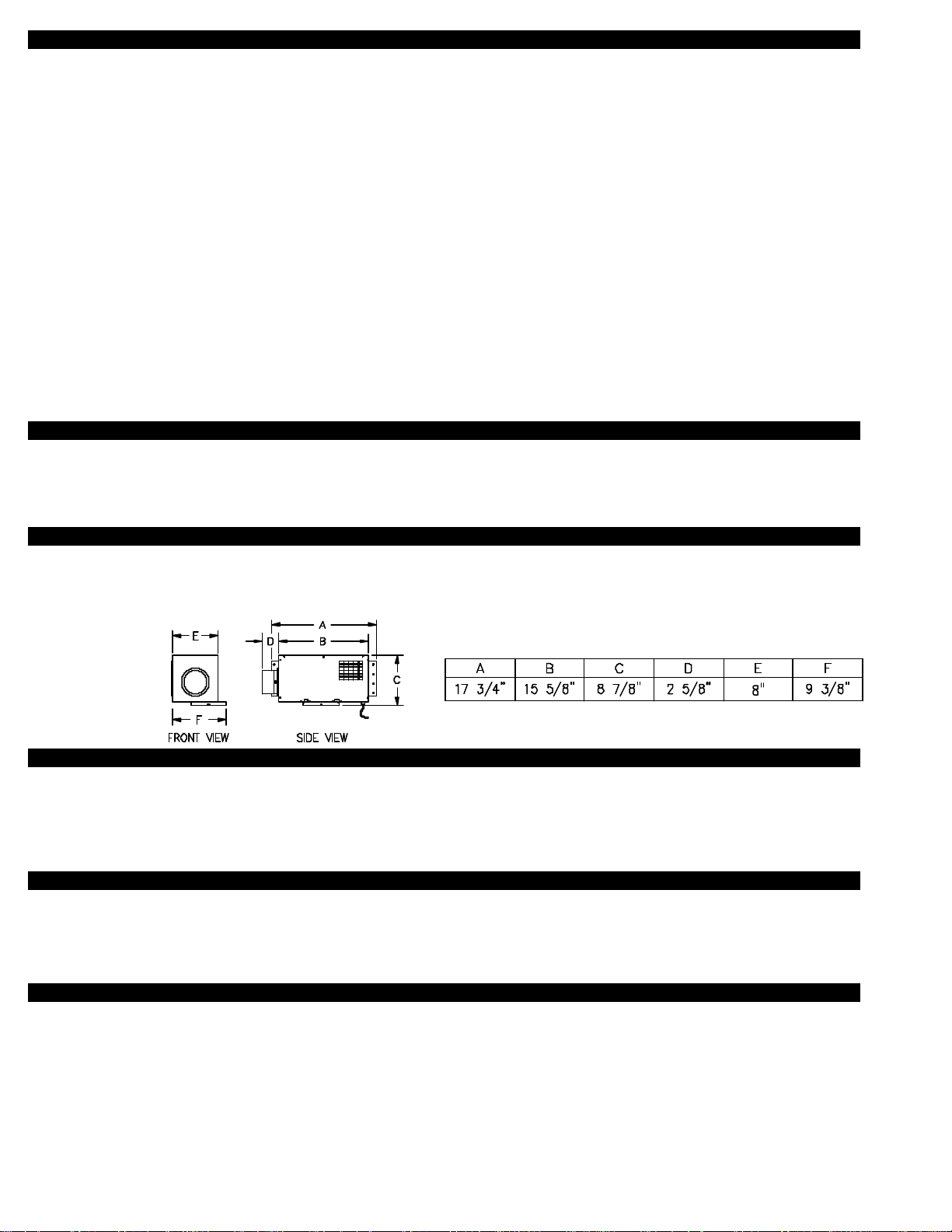
TABLE OF CONTENTS
......................................................................................................................................1
....................................................................................................................................................1
..........................................................................................................................................................................1
.....................................................................................................................................................2
..........................................................................................................................2-3
................................................................................................................................................3
....................................................................................3
................................................................................................................4-5
Tools Required ...........................................................................................................................................................5
Cutting PVC Opening through Wall ............................................................................................................................5
IN-FORCER Installation ..............................................................................................................................................6
Installation of Pipe ..................................................................................................................................................6-7
Installation of Intake Elbow .....................................................................................................................................7-8
.............................................................................................................................................8
.............................................................................................................................................................9
..................................................................................................................................................................10
...........................................................................................................................10-11
................................................................................................................................................11
.................................................................................................................................................12-13
.......................................................................................................................................................14
TM
is a trademark of Tjernlund Products, Inc. for IN-FORCER air intakes.
DESCRIPTION
-
SPECIFICATIONS
115/1/60, 1600 RPM, 80 watts, 1.0 FLA
Manual Override; Automatic adjustment, rated for 1 hp @ 125 VAC
GENERAL INFORMATION
INSTALLATION RESTRICTIONS
WARNING: Improper installation, adjustment, alterations, service or maintenance can cause injury or property damage. Refer to
this manual. For assistance or additional information consult a qualified installer, service agency or the equipment supplier.
CAUTIONS
Failure to install, maintain and/or operate the IN-FORCER in accordance with manufacturer’s instructions may result in conditions
that can produce bodily injury and property damage.
The IN-FORCER motor shaft must be mounted horizontally and with discharge facing down to prevent motor bearing wear and
ensure proper operation of the Fan Proving Switch.
The IN-FORCER must be installed level to ensure proper damper operation.
Disconnect power supply when making wire connections and servicing the IN-FORCER. Failure to do so may result in personal
injury and/or equipment damage.
Make certain the power source is adequate for the IN-FORCER requirements. Do not add the IN-FORCER to a circuit where the
total electrical load is unknown.
1
Page 3
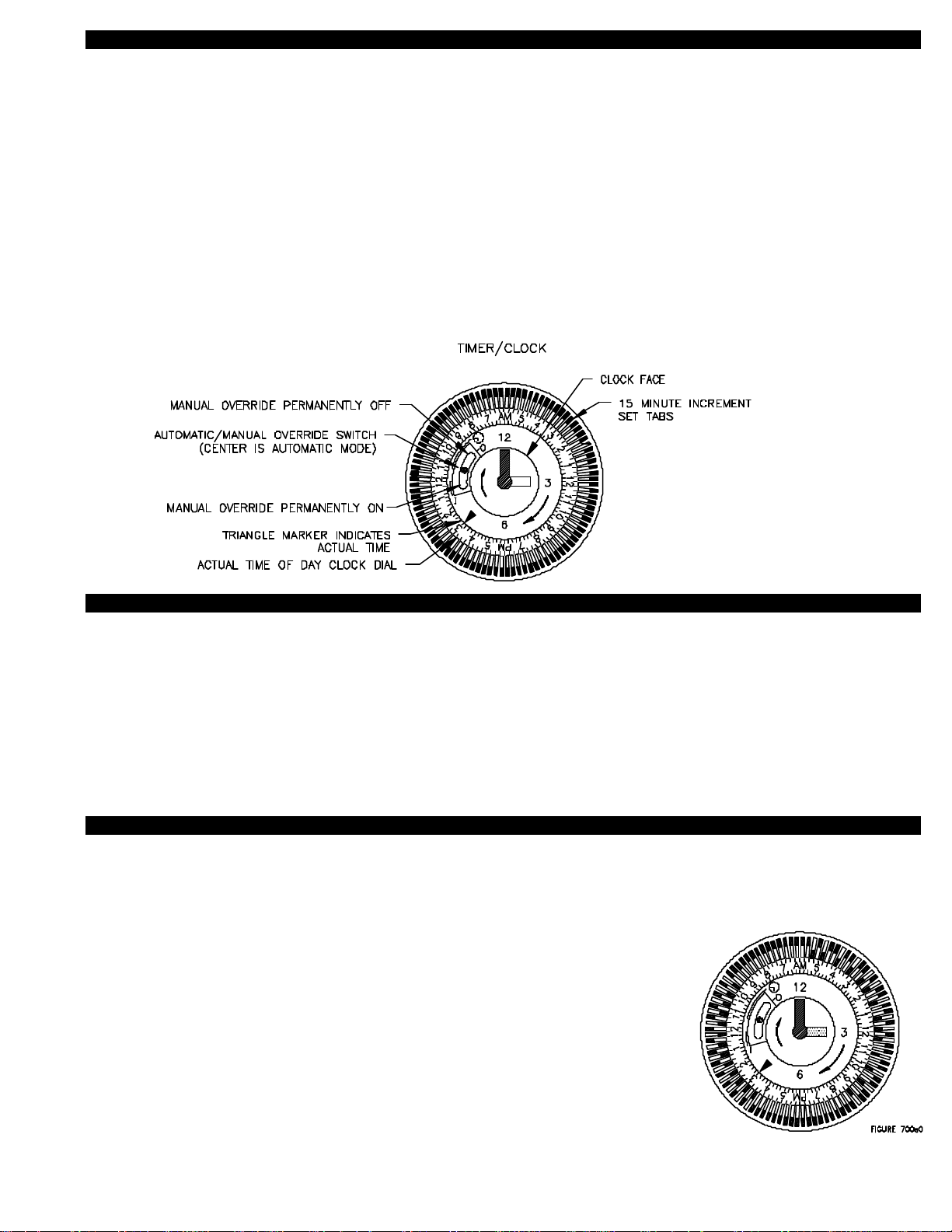
TIMER / CLOCK OPERATION
AUTOMATIC TIMER MODE
In order to operate the timer according to the desired automatic settings, the automatic/manual override switch has to be in the center
position. NOTE: If power is interrupted, the time setting will be off by how long power is interrupted for. It will be necessary to reset
to actual time if the IN-FORCER needs to operate at specific times of the day.
SETTING AUTOMATIC TIMER MODE
1. The white tabs are set for 15 minute increments for all A.M. and P.M. hours. Push tabs to the outer ring position at the desired time
intervals the IN-FORCER will be operated.
2. To reset clock to actual time, turn the outer clock dial gradually CLOCKWISE until the actual time is aligned with the triangle marker
on the inner dial. NOTE: A.M. and P.M. settings on dial.
MANUAL OVERRIDE
The IN-FORCER can be turned on so it operates continuously by switching the automatic/manual switch to "I".
The IN-FORCER may be completely turned off during seasons where adequate outside air is introduced to the house by switching the
automatic/manual switch to "O".
RECOMMENDED PATTERNS OF OPERATION
It is recommended that the Timer/Clock be programmed based on the lifestyle or needs of the occupants. For example, a family with
smokers may want to cycle the IN-FORCER more frequently than a family of non-smokers.
Another program may be to cycle the IN-FORCER during peak usage of exhaust fans, such as bathroom, kitchen, laundry or utility.
Outdoor air should be brought in at these peak times to help balance out pressure inside the house.
The IN-FORCER can be cycled on and off at regular intervals to periodically provide fresh air to the home.
The IN-FORCER may be operated continuously by moving the override switch to the "I" position. It can also be turned off during any
period in which adequate fresh air is supplied through windows by moving the override switch to the "O" position.
HYPOTHETICAL IN-FORCER OPERATION BASED ON LIFESTYLE
The example below shows a possible way in which cycling times of the IN-FORCER may be determined based on household occupant lifestyles, (See Diagram A).
6:00 A.M. to 9:00 A.M. = Outside fresh air should be brought into the house continuously to compensate for morning routines. Bathing, cooking, laundry and other activities such as smoking
necessitate that outside fresh air to be brought in. Depressurization of the house at these times is
common with many exhaust fans running at one time.
9:00 A.M. to 4:00 P.M. = House is normally vacant with parents at work and children at school.
Cycle IN-FORCER on and off for 15 minute intervals to assure fresh air is supplied to the house.
4:00 P.M. to 8:00 P.M. = Outside fresh air should be brought into the house continuously to compensate for evening routines. Bathing, cooking, laundry and other activities such as smoking
necessitate the need for outside fresh air to be brought in. Depressurization of the house at these
times is common with many exhaust fans running at one time.
DIAGRAM A
8:00 P.M. to 6:00 A.M. = All members of the household are usually present. Outside fresh air is
needed to dilute occupant generated carbon dioxide during sleeping. Cycle IN-FORCER on and
off for 15 minute intervals, with occasional 30 minute intervals to assure fresh air is supplied to house.
2
Page 4
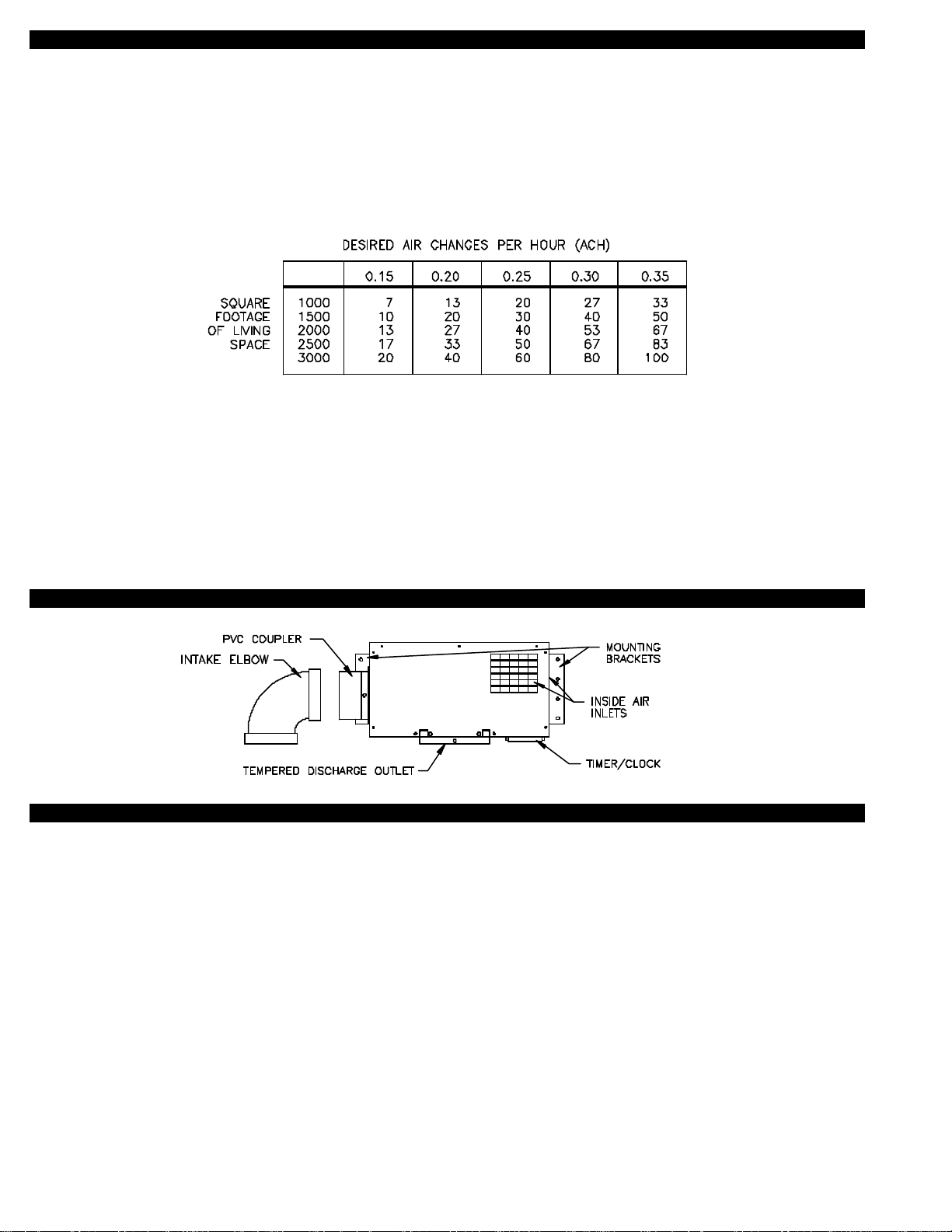
IN-FORCER OPERATION BASED ON AIR CHANGES PER HOUR
This method of operation can be used to supplement or provide for guaranteed air change rates. Table 1 shows the constant Cubic
Feet Per Minute (CFM) of air necessary to produce the desired Air Change Per Hour rate (ACH), assuming natural infiltration of outside air at a rate of .10 ACH. Square footage is determined by calculating the finished living space of the house. Garages and crawl
space should not be included. The constant CFM figures shown assume that the living space has standard 8 foot ceilings.
1. Determine square footage of house living space on left hand column.
2. Pick desired air change rate from top row.
3. Locate intersection of these points to determine constant CFM that should be obtained to meet desired ACH.
TABLE 1
Where the CFM delivery of the IN-FORCER exceeds that listed in Table 1, the Timer/Clock can be set so the IN-FORCER is cycled to
obtain the desired ACH.
EXAMPLE
2000 square feet of living space
.2 ACH desired ventilation rate equals 27 CFM
IN-FORCER capacity of 53 CFM based on Table 2, page 4.
In this example the timer may be set so that the IN-FORCER operates for one half hour straight each hour or two fifteen minute periods each hour.
IN-FORCER TERMINOLOGY
RECOMMENDED MOUNTING AND DISCHARGE TERMINATION LOCATIONS
The IN-FORCER may be mounted anywhere in the house. The best place to mount it is in an unfinished room where fan noise will
be isolated and exposed floor joists provide for easy installation. It may not be installed in a garage or area of the house where odorous or noxious fumes are present. The IN-FORCER tempers air from the room it is installed in and this may result in undesirable pol lutants being introduced into the home.
It is recommended that the IN-FORCER discharge in a location where there is not a lot of house traffic or in a manner that it will not
be directed at the occupants. Keep in mind that longer intake and discharge pipe runs reduce the CFM intake of the IN-FORCER,
(See Table 2 PAI-1T or Table 3 PAI-2T).
Do not terminate adjacent to thermostat. Although the incoming air is tempered with existing room air, severe outside temperatures
may be noticeable at the IN-FORCER discharge.
Do not terminate within three feet from a barometric draft control or intake grille of an appliance, (See Diagram K , Page 7).
3
Page 5
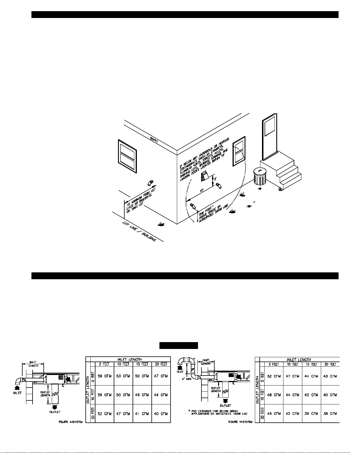
INTAKE ELBOW TERMINATION CLEARANCES
The IN-FORCER has been Listed in accordance with the 1990 BOCA national Mechanical Codes M-306.1 and M-306.1.1 as follows,
(See Diagram B).
M-306.1 LOCATION: Outside air exhaust and intake openings shall be located a minimum of 10 feet (3048mm) from lot lines or buildings on the same lot. When openings front on a street or public way, the distance shall be measured to the centerline of the street or
public way.
M-306.1.1 INTAKE OPENINGS: Outside air intake openings shall be located a minimum of 10 feet (3048mm) from any hazard or
noxious contaminant such as vents, chimneys, plumbing vents, streets, alleys, parking lots and loading docks. When a source contaminant is located within 10 feet (3048mm) of an intake opening, such opening shall be located a minimum of 2 feet (610mm) below
the contaminant source.
IN ADDITION TO THESE CODES THE MANUFACTURER RECOMMENDS THAT:
• The intake elbow should be a minimum of 1 foot above grade or anticipated snow line.
DIAGRAM B
* IF TERMINATING BELOW GRADE
OR ANTICIPATED SNOW LINE,
USE EXTENSION PROCEDURE AS
SHOWN IN TABLE 2 OR TABLE 3.
If possible, terminate the IN-FORCER on a wall that does not face the direction of prevailing
winds. This will diminish the possibility of wind induced damper fluctuation noise.
DETERMINING CFM CAPABILITIES
Reference the chart of the correct model selecting either the PAI-1T or PAI-2T. The readings for CFM are determined with various
inlet and outlet pipe lengths. The charts are read the same way except the right hand chart takes into consideration an intake elbow
that is extended up to 4’ above exterior penetration for below grade applications or to extend above anticipated snow line. The top
row of the chart has inlet 3” diameter PVC pipe lengths from 2 to 20 feet. The left hand column has outlet 6” diameter pipe lengths
from 0 to 20 feet. Pipe lengths must be calculated in equivalent feet, (See Diagram H, Page 6). With correct model selected, deter mine pipe lengths and read intersection of inlet and outlet pipe lengths to determine CFM. Consult Tjernlund Products for information
on CFM data with pipe runs longer than those indicated on the charts.
TABLE 2
MODEL PAI-1T
4
Page 6

TABLE 3
MODEL PAI-2T
INSTALLATION (TOOLS REQUIRED)
• 3-1/2” hole saw or reciprocating saw • 5/16”, 1/4” nut runner or socket
• Drill and 1/2” bit • Blade screwdriver
CUTTING PVC OPENING THROUGH WALL
Note: Before cutting opening through wall, consider layout of PVC pipe runs and confirm intake elbow termination clearances are
met as shown on page 4.
1. A) Attach template to the rim joist in between the floor joists ensuring that it is snug against the subfloor and joist that IN-FORCER
will be mounted to, (See Diagram B). If unit is to be installed on floor trusses, the template should be adjusted to compensate
for the thickness of the added plywood as described in truss mounting section below, (See Diagram C).
B) If IN-FORCER is not being installed between floor joists or trusses, attach the template to the wall it will be exiting, ensuring
IN-FORCER will be level.
DIAGRAM B
DIAGRAM C
FLOOR JOIST
2. Using 1/2” bit, drill pilot holes noted on the template from inside through rim joist, wall board, siding, etc., keeping drill bit
perpendicular to the wall. 1/2” bit must be long enough to penetrate through exterior.
3. Remove template from rim joist and attach to building exterior, aligning pilot hole markings on template with holes previously
created in Step #2.
4. Using 3-1/2” hole saw or a reciprocating saw and appropriate blade, cut opening through rim joist, wall board, siding, etc., following
the template outline for the pipe, (See Diagram D).
5. Knock out material exposing hole through the wall.
DIAGRAM D
TRUSS MOUNTING
If IN-FORCER will be mounted on a floor truss instead of a joist follow this section, otherwise, skip to installation of IN-FORCER.
1. Cut a piece of plywood measuring 22” x 9”.
FLOOR TRUSS
2. Position 22” side of plywood flush against sub floor.
3. Secure plywood to trusses with a minimum of 4-8 penny nails or 1-1/2” wood screws.
5
Page 7

INSTALLATION OF IN-FORCER
A minimum two foot length of PVC intake pipe is recommended so the IN-FORCER can be easily serviced. If intake PVC pipe
lengths are relatively short, the pipe can be cemented to the IN-FORCER coupler and fed through exterior opening before securing to
the wall. If PVC pipe run is extended, first secure IN-FORCER to joist/truss, then extend PVC pipe run through exterior opening and
cement to PVC coupler.
Note: Before cutting opening through wall, consider layout of PVC pipe runs and confirm intake elbow termination clearances are
met as shown on page 4.
1. Assemble vibration mount brackets on IN-FORCER as shown below in diagram E.
DIAGRAM E
2. Install IN-FORCER 1/2” below subfloor making sure that unit is level. NOTE: 1/2” space must be followed so PVC pipe lines up
with hole template.
3. Level IN-FORCER on underside length wise and width wise making sure it is level in both planes, (See Diagram F).
4. Once determined IN-FORCER is level, secure to wall with provided screws, (See Diagram G). Note: Drill 4 - 1/4” holes
and use wall anchors provided if installing on masonry wall.
DIAGRAM F
DIAGRAM G
INSTALLATION OF PIPE
Schedule 40 or schedule 80 3” PVC pipe is recommended on the intake side of the IN-FORCER. Standard 6” metal vent or flex duct
is acceptable for discharge vent runs. If using flex duct, make sure adherence to manufacturers restrictions is followed.
Determine the inlet and outlet pipe lengths in equivalent feet. Each 90 degree 3” PVC elbow is equal to 5 feet of straight pipe, each
45 degree elbow is equal to 2-1/2 feet of straight pipe. Each 90 degree elbow of 6” metal vent pipe is equal to 10 feet of straight pipe,
each 45 degree elbow is equal to 5 feet of straight pipe. For an example of how to calculate equivalent feet, (See Diagram H).
Plan vent runs with desired CFM requirements in mind.
EQUIVALENT PIPE LENGTH CALCULATION EXAMPLE
DIAGRAM H
* Intake elbow & gooseneck do not need to be
included for equivalent length calculation. These
exterior PVC pipe fittings have already been
accounted for in CFM calculations, (See Table 2
or 3).
6
Page 8

Plan vent runs with desired CFM requirements in mind. It is recommended that the IN-FORCER be mounted as close to the dis
-
charge location as possible to minimize the use of the more restrictive flex duct. For CFM capabilities see Table 2 or Table 3.
If using flex duct on discharge side, a take-off section of 6” diameter metal pipe or a 6” diameter metal elbow will have to be installed
on the IN-FORCER . The flex duct will then have to be connected to the take-off section by duct tape or other suitable method,
(See Diagram I).
DIAGRAM I
If flex duct will be directed to higher levels, instead of down, it is recommended that a 6” metal elbow be connected to the
IN-FORCER at discharge. Flex duct can then be connected to the elbow. All flex duct runs should be tapered gradually to prevent
severe bends and kinks that may add resistance and reduce CFM. Make bends with as large a radius as possible and keep flex duct
as straight as possible for extended runs, (See Diagram J).
DIAGRAM J
The discharge should terminated three feet from a barometric draft control or intake grille of an appliance. If this is not possible terminate on sides or opposite side of intake on appliance. Never terminate within 3 feet from the front or intake side of appliance. Supply
duct should also terminate a minimum of 18 inches above floor or other obstructions if perpendicular to them, (See Diagram K).
DIAGRAM K
INSTALLING INTAKE ELBOW
1. Insert PVC pipe through wall and cut to desired exterior termination length. NOTE: A minimum of two feet should be used for PVC
section that is connected to IN-FORCER PVC coupler. This will leave room for servicing IN-FORCER.
2. Apply PVC cement to exterior pipe joints and make connections as shown depending on exterior layout, (See Diagram L).
3. After PVC pipe, intake elbow and IN-FORCER are completely installed and secured, apply a bead of exterior rated caulk around
pipe on exterior of building, (See Diagram M).
7
Page 9

DIAGRAM L
IN-FORCER PAI-T SERIES JUNCTION BOX LADDER DIAGRAM
LADDER DIAGRAM OF PAI-T SERIES WITH OPTIONAL HUMIDISTAT
DIAGRAM M
OR
The diagram below shows the PAI-T Series with an optional line voltage humidistat wired in parallel to the Timer/Clock.
All Wiring from the PAI-T Series to the humidistat must be appropriate Class 1 wiring as follows: installed in rigid metal conduit, inter -
mediate metal conduit, rigid non-metallic conduit, electrical metallic tubing, Type MI cable, Type MC cable or can be otherwise suitably protected from physical damage.
DIAGRAM N
NOTE:
If hard-wiring IN-FORCER into electrical
box leave approximately 10” or sufficient
slack in wiring for pull-down servicing feature of IN-FORCER, (See Diagram N).
Remove six (6) screws from bottom front
and sides of IN-FORCER while holding
blower assembly firmly. Carefully slide
blower assembly down until stops hold in
place, (See Diagram O, Page 10).
8
Page 10

IN-FORCER PAI-T SERIES TROUBLESHOOTING GUIDE
SYMPTOM 1 . IN-FORCER WILL NOT RUN
Step 1.
Confirm that all 115 volt circuits are complete to the IN-FORCER.
Check the electrical plug to wall receptacle, fuses and circuit
breakers.
115V not present
Solution: Reestablish 115 volts to IN-FORCER.
115V is present
Step 2.
Move the manual override switch to the “on” position. NOTE: If
your IN-FORCER does not have a manual override switch disregard this step and turn dial to the next “on” cycle position
Result: IN-FORCER will run.
Yes
Step 3.
Return manual override switch to the center position from step 2. Move
timer dial to a pre-selected fan “on” position.
Result: IN-FORCER will run for pre-selected period of time.
Yes
Step 4.
Repeat steps 1-3 or contact Tjernlund Products for further assistance.
Step 2.1
Caution: Disconnect the 115V
power source to the IN-FORCER
before attempting the following
procedure. a) Remove the RED
No
and ORANGE wires from timer
and connect them together. b)
Reestablish 115V power source.
Result: IN-FORCER will run.
No
Solution: Replace IN-FORCER motor.
Part # 950-3022
No
Solution: Replace IN-FORCER Timer/Clock.
Part #950-0453
Solution: Replace Timer/Clock.
Part # 950-0453.
No
NOTE: For further assistance contact Tjernlund Products, Inc.
Technical Customer Service Department at 1-800-255-4208,
7:00 - 4:30 CST, M-F.
SYMPTOM 2 . IN-FORCER RUNS CONSTANTLY
Step 1.
Confirm that manual override switch is in the center position.
NOTE: If your IN-FORCER does not have a manual override
switch disregard this step and turn dial to next “off” cycle position.
Yes
Step 2.
CAUTION: Use extreme caution when removing RED wire, 115V
is present. With the IN-FORCER running, remove the RED wire
from the Timer/Clock.
Result: IN-FORCER shuts off immediately.
Yes
Step 3.
Solution: Replace Timer/Clock
Part # 950-0453
Solution: Move the manual override switch to the center position (auto).
No
No
Solution: Contact Tjernlund
Products for further assistance.
NOTE: For further assistance contact Tjernlund Products, Inc.
Technical Customer Service Department at 1-800-255-4208,
7:00 - 4:30 CST, M-F.
9
Page 11

MAINTENANCE
The IN-FORCER must be inspected every 3 to 6 months. Points of inspection are:
1. Motor: Motor must rotate freely. The fan motor is permanently sealed and requires no oiling.
2. Wheel: Wheel must be clean of any foreign substance like leaves, lint or other items. Remove all foreign material from
blower assembly before operation.
3. Intake Elbow: Intake elbow screen should be clear of any foreign substance like leaves, lint or other items. Check screen
every 3 to 6 months for foreign material. Remove all foreign material from intake system before operation.
The IN-FORCER now features easy pull down servicing for maintenance, (See Diagram O).
IN-FORCER ISOMETRIC PARTS DIAGRAM
DIAGRAM O
NOTE:
For pull-down servicing feature of
IN-FORCER, remove six (6)
screws from bottom front and
sides of IN-FORCER while holding
blower assembly firmly. Carefully
slide blower assembly down until
stops hold in place.
how
HOW TO OBTAIN SERVICE ASSISTANCE
1. If you have any questions about your IN-FORCER or if it requires adjustment, repair or routine maintenance, we suggest that
you contact your installer, contractor or service agency.
2. If you require technical information contact Tjernlund Products, Inc. at 1-800-255-4208 or email us at fanmail@tjfans.com.
When contacting Tjernlund Products, Inc., please have the following information available:
1. Model number and date code of the IN-FORCER
2. Name and address of installer and service agency
3. Date of original installation and dates any service work was performed
4. Details of the problem
LIMITED PARTS WARRANTY AND CLAIM PROCEDURE
Tjernlund Products, Inc. warrants the components of the IN-FORCER for one year from date of installation. This warranty covers
defects in material and workmanship. This warranty does not cover normal maintenance, transportation or installation charges for
replacement parts or any other service calls or repairs. This warranty DOES NOT cover the complete IN-FORCER if it is operative,
except for the defective part.
Tjernlund Products, Inc. will issue credit or provide a free part to replace one that becomes defective during the one year warranty period. If the part is over 18 months old, proof of date of the installation in the form of the contractor sales / installation receipt is necessary
to prove the unit has been in service for under one year. All receipts should include the date code of the IN-FORCER to ensure that the
defective component corresponds with the complete unit. This will help preclude possible credit refusal.
10
Page 12

1.)
Follow troubleshooting guide to determine defective component. If unable to determine faulty component, contact your
Tjernlund distributor, Tjernlund Products Technical Customer Service Department at 1-800-255-4208 for troubleshooting
assistance or email us at fanmail@tjfans.com.
2.) After the faulty component is determined, return it to your Tjernlund distributor for replacement. Please include IN-FORCER date
code component was taken from. The date code is located on the bottom of IN-FORCER cabinet. If the date code is older than
18 months you will need to provide a copy of the original installation receipt to your distributor. Credit or replacement will only be
issued to a Tjernlund distributor after the defective part has been returned prepaid to Tjernlund.
COVERED PARTS
Motor Timer/Clock Blower Wheel
WHAT IS NOT COVERED
Product installed contrary to our installation instructions
Product that has been altered, neglected or misused
Product that has been wired incorrectly
Product that has been damaged by a malfunctioning or mistuned burner
Any freight charges related to the return of the defective part
Any labor charges related to evaluating and replacing the defective part
TJERNLUND LIMITED ONE YEAR WARRANTY
Tjernlund Products, Inc. warrants to the original purchaser of this product that the product will be free from defects due to faulty material or workmanship for a period of (1) year from the date of original purchase or delivery to the original purchaser, whichever is earlier. Remedies under this warranty are limited to repairing or replacing, at our option, any product which shall, within the above stated warranty period, be returned to Tjernlund Products, Inc. at the address listed below, postage prepaid. THERE ARE NO WARRANTIES WHICH EXTEND BEYOND THE DESCRIPTION ON THE
FACE HEREOF, AND TJERNLUND PRODUCTS, INC. EXPRESSLY DISCLAIMS LIABILITY FOR INCIDENTAL OR CONSEQUENTIAL DAMAGES ARISING FROM THE USE OF THIS PRODUCT.
THIS WARRANTY IS IN LIEU OF ALL OTHER EXPRESS WARRANTIES AND NO AGENT IS AUTHORIZED TO ASSUME FOR US ANY LIABILITY ADDITIONAL TO THOSE SET FORTH IN THIS
LIMITED WARRANTY. IMPLIED WARRANTIES ARE LIMITED TO THE STATED DURATION OF THIS LIMITED WARRANTY. Some states do not allow limitation on how long an implied warranty
lasts, so that limitation may may not apply to you. In addition, some states do not allow the exclusion or limitation of incidental or consequential damages, so that above limitation or exclusion may
not apply to you. This warranty gives you specific legal rights and you may also have other rights which may vary from state to state. Send all inquires or products requiring warranty work to Tjernlund
Products, Inc. 1601 9th Street, White Bear Lake, MN 55110-6794 (651) 426-2993 or email us at fanmail@tjfans.com.
MOTOR KIT 950-3022
PAI-1 WHEEL KIT 950-0451
PAI-2 WHEEL KIT 950-0457
TIMER/CLOCK KIT 950-0453
IN-FORCER REPLACEMENT PARTS LIST
11
Page 13

INSTALLER COMMENTS
12
Page 14

INSTALLER COMMENTS
13
Page 15

TEMPLATE MAY NOT
BE TO SCALE.
14
 Loading...