

Page 1
TJERNLUND PRODUCTS, INC.
1601 Ninth Street • White Bear Lake, MN 55110-6794
PHONE (800) 255-4208 • (651) 426-2993 • FAX (651) 426-9547
Visit our web site • www.tjernlund.com
TM
IN-FORCER
MODELS
PAI-1G & PAI-2G
PAI-10 & PAI-2O
REV. A 5/01
INSTALLATION INSTRUCTIONS
OWNER'S INSTRUCTIONS, DO NOT DESTROY
THIS DEVICE MUST BE INSTALLED BY A
QUALIFIED PERSON.
READ INSTRUCTIONS CAREFULLY PRIOR TO INSTALLATION
AND OPERATION OF THE AIR INTAKE SYSTEM.
Copyright © 2001, Tjernlund Products, Inc. All rights reserved. P/N 8504038
Page 2
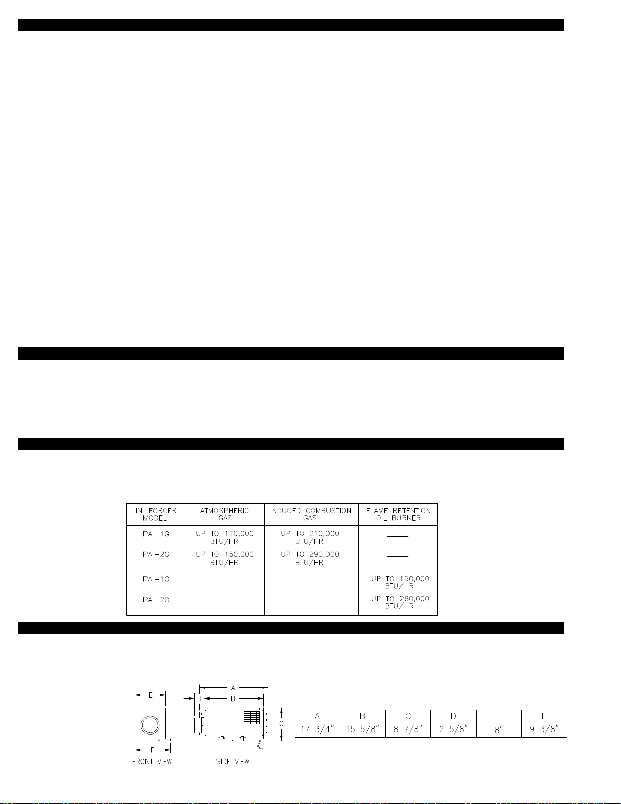
TABLE OF CONTENTS
Descriptions and Specifications ......................................................................................................................................1
Installation Restrictions....................................................................................................................................................2
Cautions ..........................................................................................................................................................................2
Safety Inspection of a Previously Used Appliance ......................................................................................................2-3
IN-FORCER Terminology................................................................................................................................................3
Intake Elbow Termination Clearances.............................................................................................................................3
Combustion CFM Necessary For Appliance(s)...............................................................................................................4
Determining IN-FORCER CFM capabilities ....................................................................................................................4
Installation
Tools Required ...............................................................................................................................................................4
Cutting PVC Opening through Wall..............................................................................................................................4-5
IN-FORCER Installation...............................................................................................................................................5-6
Installation of Pipe .......................................................................................................................................................6-7
Confined Space or Closet Installations ...........................................................................................................................7
Installation of Intake Elbow..............................................................................................................................................7
Electrical Wiring
System Operation Check Out........................................................................................................................................13
Maintenance..................................................................................................................................................................13
Trouble Shooting
How to Obtain Service & Warranty ..........................................................................................................................16-17
Replacement Parts List & Isometric IN-FORCER Diagram ..........................................................................................17
PVC Hole Template.......................................................................................................................................................18
Wiring IN-FORCER Models PAI-1O & PAI-2O ............................................................................................8-10
Wiring IN-FORCER Models PAI-1G & PAI-2G ..........................................................................................10-13
Wiring IN-FORCER PAI-G Series With a 24V Furnace/Boiler and Millivolt Water Heater .............................11
Wiring IN-FORCER Models PAI-1G & PAI-2G With Single Zone Gas or Oil Terminal Strip/Fan Center .......13
IN-FORCER Models PAI-1O & PAI-2O ...........................................................................................................14
IN-FORCER Models PAI-1G & PAI-2G......................................................................................................15-16
IN-FORCERTMis a trademark of Tjernlund Products, Inc. for IN-FORCER air intakes.
DESCRIPTION
The IN-FORCER combustion fans are mechanical air intake fans designed and Listed for use with atmospheric or induced combustion natural draft gas or oil heating equipment. The IN-FORCER functions as a source of combustion air. Outside intake air is blended with a larger quantity of indoor air so the resulting tempered discharge does not reflect outside temperature extremes. The
IN-FORCER assures intake air is supplied by monitoring the airflow with a Fan Proving Switch. The main burner will be interrupted if
a malfunction occurs.
APPLICATION TABLE
Verify that the total BTU/hr input of the heating appliance(s) fall within the ratings listed below. Check CFM necessary for the BTU/hr
input of the heating appliance(s) on table 1, page 4. CFM delivered depends upon the total length of pipe used. Check CFM capacity
with different inlet and outlet pipe lengths on page 4, Table 2 PAI-1 Series or Table 3 PAI-2 Series.
SPECIFICATIONS
Motor: 115/1/60, 1600 RPM, 80 watts, 1.0 FLA
Fan Prover: Non-adjustable, contacts rated for 3 Amps Inductive @ 120VAC
Relay: 24/115V Switching Relay, PAI-1G & PAI-2G
1
Page 3

GENERAL INFORMATION
These units have been factory tested and rated in accordance with AMCA standard 210, test code for air moving devices.
Each IN-FORCER is electrically factory line tested before shipment.
After opening carton, Inspect thoroughly for hidden damage. Fan wheel should rotate freely. If any damage is found, notify freight
carrier and your distributor immediately and file a concealed damage claim.
INSTALLATION RESTRICTIONS
1. The electrical load controlled through the Fan Proving Switch must not exceed its nameplate ratings.
2. Observe proper location of intake elbow as described on page 3.
WARNING: Improper installation, adjustment, alterations, service or maintenance can cause injury or property damage. Refer to
this manual. For assistance or additional information consult a qualified installer, service agency or the equipment supplier.
CAUTIONS
1. Failure to install, maintain and/or operate the IN-FORCER in accordance with manufacturer’s instructions may result in conditions
that can produce bodily injury and property damage.
2. The IN-FORCER must be installed by a qualified installer (an individual properly licensed and/or trained) in accordance with all
local codes or in their absence, in accordance with the appropriate National Fire Protection Association #31, #54, #211 and the
National Electric Code.
3. The IN-FORCER motor shaft must be mounted horizontally and with discharge facing down to prevent motor bearing wear and
ensure proper operation of the Fan Proving Switch.
4. The IN-FORCER must be installed level to ensure proper damper operation.
5. Disconnect power supply when making wire connections and servicing the IN-FORCER. Failure to do so may result in personal
injury and/or equipment damage.
6. Make certain the power source is adequate for the IN-FORCER requirements. Do not add the IN-FORCER to a circuit where the
total electrical load is unknown.
WARNING: The IN-FORCER CFM outputs are estimates that will assure adequate combustion air is supplied if the appliance is
functioning properly. However, in the event that there is an appliance malfunction, such as a cracked heat exchanger or clogged
flue, there is no guarantee that additional combustion air will eliminate carbon monoxide spillage into the home.
SAFETY INSPECTION OF A PREVIOUSLY USED OIL APPLIANCE
(Perform prior to IN-FORCER installation)
The following procedure is intended as a guide to aid in determining that an appliance is properly installed and is in safe condition for
continuing use. This procedure is based on central furnace and boiler installations and it should be recognized that generalized procedures cannot anticipate all situations. Accordingly, in some cases deviation from this procedure may be necessary to determine
safe operation of the equipment.
A. This procedure should be performed prior to any attempt at modifications of the appliance or installation of the IN-FORCER.
B. If it is determined there is a condition which could result in unsafe operation, the appliance should be shut off and the owner
advised of the unsafe condition.
The following steps should be followed in making the safety inspection:
1. Visually inspect the venting system and determine there is no blockage or restriction, leakage, corrosion or other deficiencies
which could cause an unsafe condition.
2. Inspect burner and primary control for proper operation.
3. Applicable only to furnaces: Inspect heat exchanger for cracks, openings or excessive corrosion. Check both the limit control
and fan control for proper operation.
4. Applicable only to boilers: Inspect for evidence of water or combustion product leaks. Determine that the water pumps are in
operating condition. Test low water cutoffs, automatic feed controls, pressure and temperature limit controls and relief valves in
accordance with the manufacturer's recommendations to determine that they are in operating order.
SAFETY INSPECTION OF A PREVIOUSLY USED GAS APPLIANCE
(Perform prior to IN-FORCER installation)
The following procedure is intended as a guide to aid in determining that an appliance is properly installed and is in safe condition for
continuing use. This procedure is based on central furnace and boiler installations and it should be recognized that generalized procedures cannot anticipate all situations. Accordingly, in some cases deviation from this procedure may be necessary to determine
safe operation of the equipment.
A. This procedure should be performed prior to any attempt at modifications of the appliance or installation of the IN-FORCER.
2
Page 4
B.
If it is determined there is a condition which could result in unsafe operation, the appliance should be shut off and the owner
advised of the unsafe condition.
The following steps should be followed in making the safety inspection:
1. Conduct a gas leakage test of the appliance piping and control system downstream of the shutoff valve in the supply line to the
appliance.
2. Visually inspect the venting system and determine there is no blockage or restriction, leakage, corrosion and other deficiencies
which could cause an unsafe condition.
3. Shut off all gas to the appliance(s).
4. Inspect burners and crossovers for blockage and corrosion.
5. Applicable only to furnaces: Inspect heat exchanger for cracks, openings or excessive corrosion. Check both the limit control
and fan control for proper operation.
6. Applicable only to boilers: Inspect for evidence of water or combustion product leaks. Determine that the water pumps are in
operating condition. Test low water cutoffs, automatic feed controls, pressure and temperature limit controls and relief valves in
accordance with the manufacturer's recommendations to determine that they are in operating order.
* Excerpts from the National Fuel Gas Code (ANSI Z223.1/NFPA #54), Appendix H.
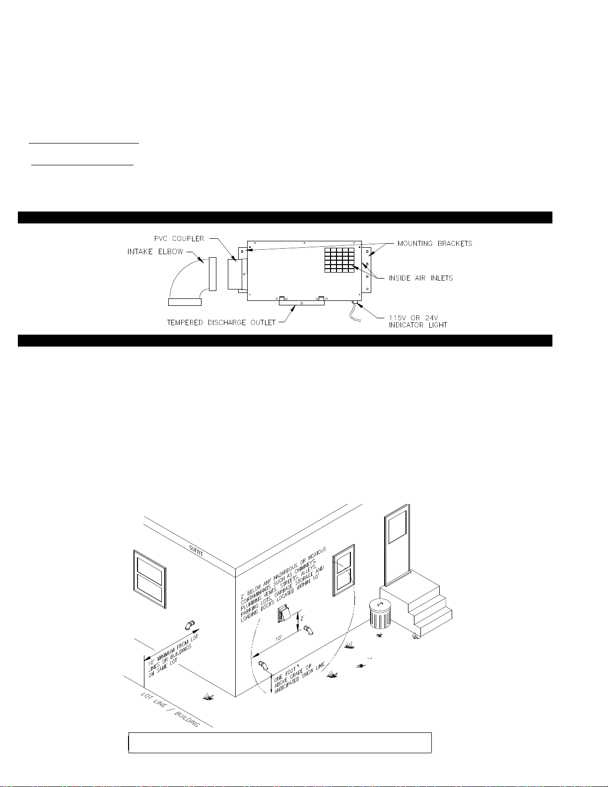
IN-FORCER TERMINOLOGY
INTAKE ELBOW TERMINATION CLEARANCES
The IN-FORCER has been Listed in accordance with the 1990 BOCA national Mechanical Codes M-306.1 and M-306.1.1 as follows,
(See Diagram A).
M-306.1 LOCATION: Outside air exhaust and intake openings shall be located a minimum of 10 feet (3048mm) from lot lines or buildings on the same lot. When openings front on a street or public way, the distance shall be measured to the centerline of the street or
public way.
M-306.1.1 INTAKE OPENINGS: Outside air intake openings shall be located a minimum of 10 feet (3048mm) from any hazard or
noxious contaminant such as vents, chimneys, plumbing vents, streets, alleys, parking lots and loading docks. When a source contaminant is located within 10 feet (3048mm) of an intake opening, such opening shall be located a minimum of 2 feet (610mm) below
the contaminant source.
IN ADDITION TO THESE CODES THE MANUFACTURER RECOMMENDS THAT:
• The intake elbow should be a minimum of 1 foot above grade or anticipated snow line.
DIAGRAM A
* IF TERMINATING BELOW GRADE
OR ANTICIPATED SNOW LINE, USE
EXTENSION PROCEDURE AS
SHOWN IN TABLE 2 OR TABLE 3.
If possible, terminate the IN-FORCER on a wall that does not face the direction of prevailing
winds. This will diminish the possibility of wind induced damper fluctuation noise.
3
Page 5
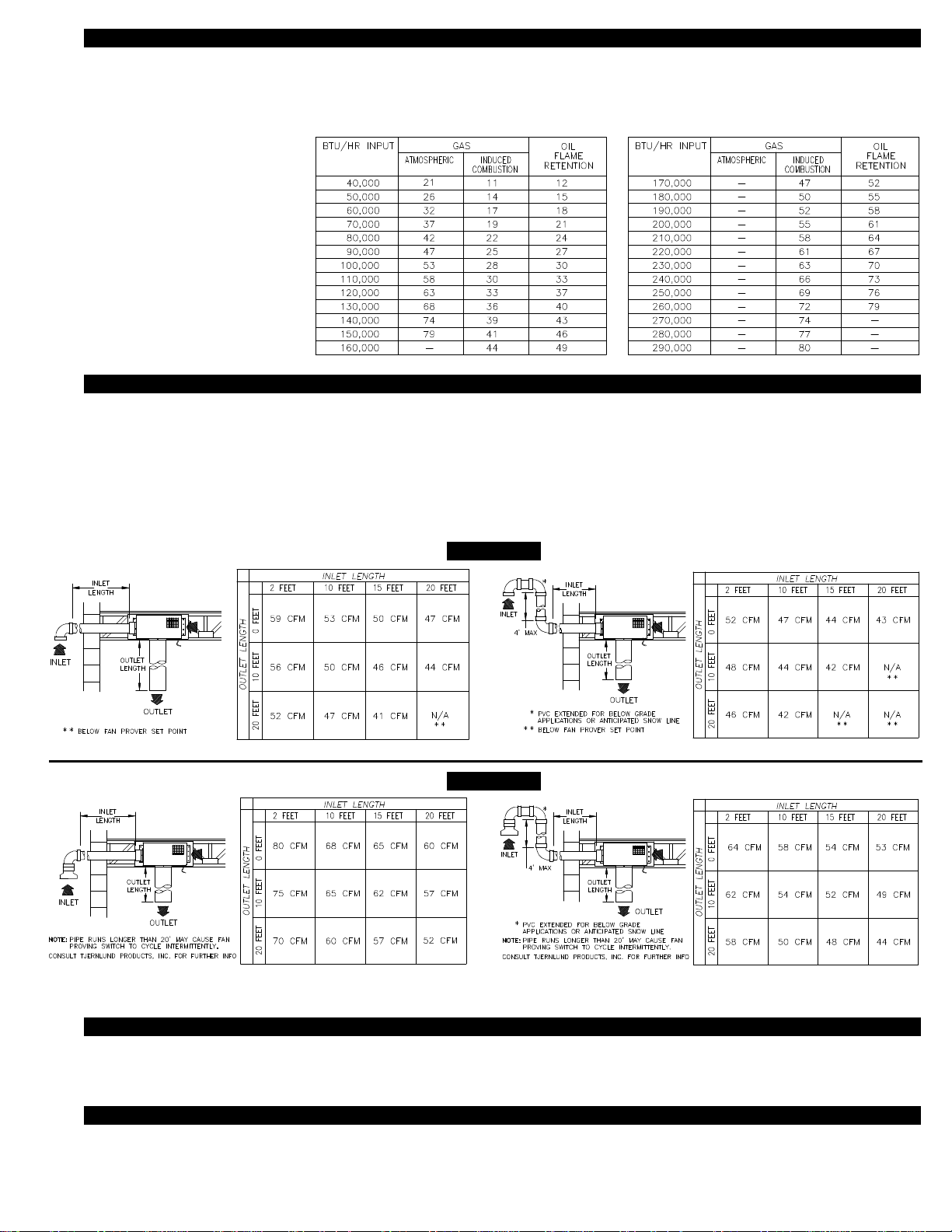
COMBUSTION CFM NECESSARY FOR APPLIANCE
The type of appliance the IN-FORCER is being interlocked with will have to be considered when determining the minimum CFM for
combustion purposes. Consult chart for recommended minimum CFM needed to fulfill combustion air requirements, (See Table 1).
TABLE 1
Note:
The PAI-1 Series maximum
capacity is 59 CFM.
The PAI-2 Series maximum
capacity is 80 CFM.
DETERMINING CFM CAPABILITIES
Reference the chart of the correct model selecting either the PAI-1 or PAI-2 series. The readings for CFM are determined with various inlet and outlet pipe lengths. The charts are read the same way except the right hand chart takes into consideration an intake
elbow that is extended up to 4’ above exterior penetration for below grade applications or to extend above anticipated snow line. The
top row of the chart has inlet 3” diameter PVC pipe lengths from 2 to 20 feet. The left hand column has outlet 6” diameter pipe
lengths from 0 to 20 feet. Pipe lengths must be calculated in equivalent feet, (See Diagram H, Page 6). With correct model selected,
determine pipe lengths and read intersection of inlet and outlet pipe lengths to determine CFM. Consult Tjernlund Products for information on CFM data with pipe runs longer than those indicated on the charts.
TABLE 2
TABLE 3
PAI-1 SERIES
PAI-2 SERIES
INSTALLATION (TOOLS REQUIRED)
• 3-1/2” hole saw or reciprocating saw • 5/16”, 1/4” nut runner or socket • Wire cutter/stripper
• Drill and 1/2” bit • Blade screwdriver
CUTTING PVC OPENING THROUGH WALL
Note: Before cutting opening through wall, consider layout of PVC pipe runs and consult performance charts above to make sure
CFM necessary for equipment is achieved with pipe run lengths.
4
Page 6
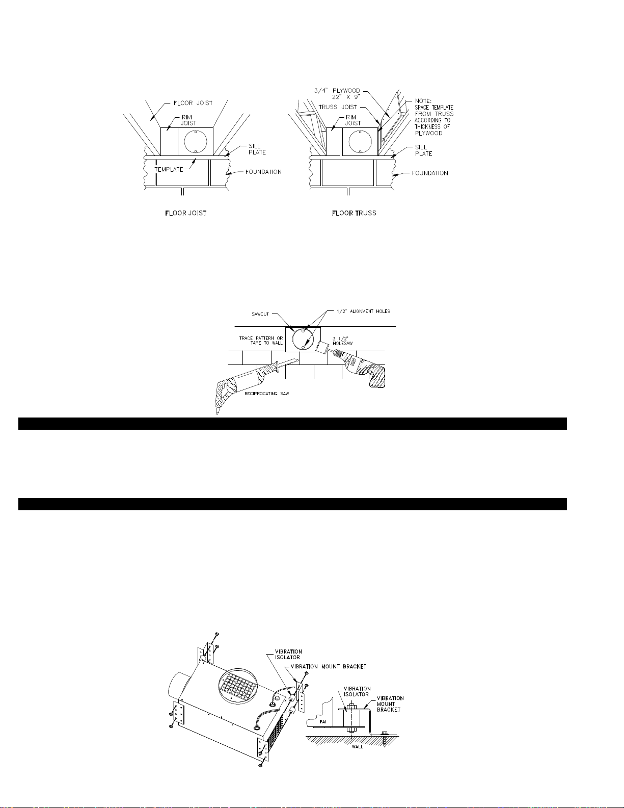
1.
A) Attach template to the rim joist in between the floor joists ensuring that it is snug against the subfloor and joist that IN-FORCER
will be mounted to, (See Diagram B). If unit is to be installed on floor trusses, the template should be adjusted to compensate
for the thickness of the added plywood as described in truss mounting section below, (See Diagram C).
B) If IN-FORCER is not being installed between floor joists or trusses, attach the template to the wall it will be exiting, ensuring
IN-FORCER will be level.
DIAGRAM B
2. Using 1/2” bit, drill pilot holes noted on the template from inside through rim joist, wall board, siding, etc., keeping drill bit
perpendicular to the wall. 1/2” bit must be long enough to penetrate through exterior.
3. Remove template from rim joist and attach to building exterior, aligning pilot hole markings on template with holes previously
created in Step #2.
4. Using 3-1/2” hole saw or a reciprocating saw and appropriate blade, cut opening through rim joist, wall board, siding, etc., following
the template outline for the pipe, (See Diagram D).
5. Knock out material exposing hole through the wall.
DIAGRAM D
DIAGRAM C
TRUSS MOUNTING
If IN-FORCER will be mounted on a floor truss instead of a joist follow this section, otherwise, skip to installation of IN-FORCER.
1. Cut a piece of plywood measuring 22” x 9”.
2. Position 22” side of plywood flush against sub floor.
3. Secure plywood to trusses with a minimum of 4-8 penny nails or 1-1/2” wood screws.
INSTALLATION OF IN-FORCER
A minimum two foot length of PVC intake pipe is recommended so the IN-FORCER can be easily serviced. If intake PVC pipe
lengths are relatively short, the pipe can be cemented to the IN-FORCER coupler and fed through exterior opening before securing to
the wall. If PVC pipe run is extended, first secure IN-FORCER to joist/truss, then extend PVC pipe run through exterior opening and
cement to PVC coupler.
Note: Before cutting opening through wall, consider layout of PVC pipe runs and consult performance charts on page 4 to make sure
CFM necessary for equipment is achieved with pipe run lengths.
1. Assemble vibration mount brackets on IN-FORCER as shown below in diagram E.
DIAGRAM E
5
Page 7

2.
Install IN-FORCER 1/2” below subfloor making sure that unit is level. NOTE: 1/2” space must be followed so PVC
pipe lines up
with hole template.
3. Level IN-FORCER on underside length wise and width wise making sure it is level in both planes, (See Diagram F).
4. Once determined IN-FORCER is level, secure to wall with provided screws, (See Diagram G). Note: Drill 4 - 1/4” holes
and use wall anchors provided if installing on masonry wall.
DIAGRAM F
DIAGRAM G
INSTALLATION OF PIPE
Schedule 40 or schedule 80 3” PVC pipe is recommended on the intake side of the IN-FORCER. Standard 6” metal vent or flex duct
is acceptable for discharge vent runs. If using flex duct, make sure adherence to manufacturers restrictions is followed.
Determine the inlet and outlet pipe lengths in equivalent feet. Each 90 degree 3” PVC elbow is equal to 5 feet of straight pipe, each
45 degree elbow is equal to 2-1/2 feet of straight pipe. Each 90 degree elbow of 6” metal vent pipe is equal to 10 feet of straight pipe,
each 45 degree elbow is equal to 5 feet of straight pipe. For an example of how to calculate equivalent feet, (See Diagram H).
Plan vent runs with desired CFM requirements in mind.
EQUIVALENT PIPE LENGTH CALCULATION EXAMPLE
DIAGRAM H
* Intake elbow & gooseneck do not need to be
included for equivalent length calculation. These
exterior PVC pipe fittings have already been
accounted for in CFM calculations, (See Page 4,
Table 2 or 3).
Plan vent runs with desired CFM requirements in mind. It is recommended that the IN-FORCER be mounted as close to the discharge location as possible to minimize the use of the more restrictive flex duct. For CFM capabilities see Page 4, Table 2 or 3.
If using flex duct on discharge side, a take-off section of 6” diameter metal pipe or a 6” diameter metal elbow will have to be installed
on the IN-FORCER . The flex duct will then have to be connected to the take-off section by duct tape or other suitable method,
(See Diagram I).
DIAGRAM I
6
Page 8

If flex duct will be directed to higher levels, instead of down, it is recommended that a 6” metal elbow be connected to the
IN-FORCER at discharge. Flex duct can then be connected to the elbow. All flex duct runs should be tapered gradually to prevent
severe bends and kinks that may add resistance and reduce CFM. Make bends with as large a radius as possible and keep flex duct
as straight as possible for extended runs, (See Diagram J).
DIAGRAM J
The discharge should terminated three feet from a barometric draft control or intake grille of an appliance. If this is not possible terminate on sides or opposite side of intake on appliance. Never terminate within 3 feet from the front or intake side of appliance. Supply
duct should also terminate a minimum of 18 inches above floor or other obstructions if perpendicular to them, (See Diagram K).
DIAGRAM K
CONFINED SPACE OR CLOSET INSTALLATIONS
The IN-FORCER can be installed in a closet or combustion air can be ducted into the closet. First, determine the CFM necessary for
proper combustion of appliance, (See Table 1, Page 4). Second, determine CFM capabilities with proposed vent runs, (See Page 4
Table 2 or 3). Keep in mind that all vent pipe equivalent lengths must be calculated, (See Diagram H, Page 6).
The discharge should terminate three feet from a barometric draft control or air intake of an appliance. If this is not possible terminate
on sides or opposite side of intake on appliance. Never terminate within 3 feet from the front or intake side of appliance. Discharge
should also terminate a minimum of 18 inches above floor or other obstructions if perpendicular to them, (See Diagram K).
With today’s higher efficient appliances, constricted spaces seldom experience elevated ambient temperatures. Because the
IN-FORCER brings in outdoor air to the space, the potential for elevated ambient temperatures is further reduced. Ventilation openings are not required for the proper operation of the IN-FORCER nor for combustion air.
INSTALLING INTAKE ELBOW
1. Insert PVC pipe through wall and cut to desired exterior termination length. NOTE: A minimum of two feet should be used for PVC
section that is connected to IN-FORCER PVC coupler. This will leave room for servicing IN-FORCER.
2. Apply PVC cement to exterior pipe joints and make connections as shown depending on exterior layout, (See Diagram L).
3. After PVC pipe, intake elbow and IN-FORCER are completely installed and secured, apply a bead of exterior rated caulk around
pipe on exterior of building, (See Diagram M).
DIAGRAM L
DIAGRAM M
OR
7
Page 9

ELECTRICAL WIRING OF IN-FORCER MODELS PAI-1O & PAI-20 (OIL)
All wiring from the IN-FORCER to the appliance must be appropriate Class 1 wiring as follows: installed in rigid metal conduit, intermediate conduit, rigid non-metallic conduit, electrical metallic tubing, Type MI Cable, Type MC Cable or be otherwise suitably protected from physical damage. The electrical contact rating for the Fan Proving Switch is 3 Amps Inductive. The Fan Proving Switch is
not suitable for loads which exceed the above limit.
SEQUENCE OF OPERATION WITH IN-FORCER INTERLOCKED ON OIL FIRED APPLIANCES
As the thermostat /aquastat senses a call for heat the internal switch of the the thermostat/aquastat will close. The switch closure
sends current through the internal controls of appliance (i.e. high limit, low limit and all other safety controls the appliance is equipped
with) and continues through the R8184G primary control. Current will then flow out of the orange of the R8184G to the IN-FORCER
motor. After draft is established within the IN-FORCER, the damper opens closing Fan Proving Switch safety circuit contacts. This
completes the circuit to the 115V indicator light and the burner motor. It is important to remember that the electrical interlock of the
IN-FORCER is always done at the final signal which would normally start the burner motor. All thermostats, zones, limits and circulators are to be wired as normally done on a chimney vented appliance.
If your appliance is not equipped with a R8184G as outlined in these diagrams, locate the wire from the primary control which is connected to the black burner motor wire and follow the steps outlined at the top of page 9.
NOTE: The indicator light on the IN-FORCER signals that it is functioning properly. If the light is on and appliance will not fire, there
may be an appliance malfunction or wiring error in the interlock. See troubleshooting section for further details.
NOTE:
For all wiring into IN-FORCER leave
approximately 10” or sufficient slack in
wiring for pull-down servicing feature of
IN-FORCER. See diagrams to right.
Remove six (6) screws from bottom front
and sides of IN-FORCER while holding
blower assembly firmly. Carefully slide
blower assembly down until stops hold in
place. See diagram on page 17.
IN-FORCER MODELS PAI-10 & PAI-20 JUNCTION BOX LADDER DIAGRAM
CAUTION
ALL WIRING FROM THE
IN-FORCER TO APPLIANCE
MUST BE CLASS 1
NOTE:
For access to IN-FORCER electrical box, remove six
(6) screws from bottom front and sides of IN-FORCER
while holding blower assembly firmly. Carefully slide
blower assembly down until stops hold in place. See
diagram on page 17.
8
Page 10

IN-FORCER MODELS PAI-1O & PAI-2O CONNECTED TO AN R8184G WITH THE APPLIANCE
(BURNER MOTOR LESS THAN 3 AMPS INDUCTIVE @ 120 VAC)
NOTES: The IN-FORCER is always interlocked with the primary control of the appliance. Wire all other furnace/boiler controls as normally done when conventional venting before continuing. Disconnect power from the appliance before attempting to interlock IN-FORCER.
Step 1: Disconnect BLACK burner motor wire from the ORANGE wire on R8184G.
Step 2: Connect the BLACK burner motor wire to the YELLOW wire in IN-FORCER electrical box.
Step 3: Connect the ORANGE wire from R8184G to the BLACK wire in IN-FORCER electrical box.
Important: The ORANGE wire from R8184G should also be connected to the Ignition Transformer or Oil Valve.
Step 4: Connect the GREEN wire in IN-FORCER electrical box to the GREEN or ground wire of burner motor
Step 5: Connect the WHITE wire in IN-FORCER electrical box to the WHITE wire of R8184G.
IN-FORCER MODELS PAI-1O & PAI-20 CONNECTED TO AN R8184G WITH TJERNLUND SS1 OR SS2 POWER VENTER
(BURNER MOTOR LESS THAN 3 AMPS INDUCTIVE @ 120 VAC)
NOTES: The IN-FORCER is always interlocked with the primary control of the appliance. Wire all other furnace/boiler controls as normally done when conventional venting before continuing. Disconnect power from the appliance before attempting to interlock IN-FORCER.
The instructions below assume that the IN-FORCER and SS1 are installed at the same time.
Step 1: Disconnect the BLACK burner motor wire from the ORANGE wire on R8184G.
Step 2: Connect the BLACK burner motor wire to the YELLOW wire in IN-FORCER electrical box.
Step 3: Connect the ORANGE wire on R8184G to terminal O in SS1 electrical box.
Important: The ORANGE wire from R8184G should also be connected to the Ignition Transformer or Oil Valve.
Step 4: Connect terminal Y on SS1 terminal strip to the BLACK wire in IN-FORCER electrical box.
Step 5: Connect the GREEN wire in IN-FORCER electrical box to the GREEN or ground wire of burner motor.
Step 6: Connect the WHITE wire in IN-FORCER electrical box to the WHITE wire of R8184G.
9
Page 11

IN-FORCER MODELS PAI-1O & PAI-2O CONNECTED TO AN R8184G WITH TJERNLUND HST POWER VENTER
(BURNER MOTOR LESS THAN 3 AMPS INDUCTIVE @ 120 VAC)
NOTES: The IN-FORCER is always interlocked with the primary control of the appliance. Wire all other furnace/boiler controls as normally done when conventional venting before continuing. Disconnect power from the appliance before attempting to interlock IN-FORCER.
The instructions below assume that the IN-FORCER and HST are installed at the same time.
Step 1: Disconnect the BLACK burner motor wire from the ORANGE wire on R8184G.
Step 2: Connect the BLACK burner motor wire to the YELLOW wire in IN-FORCER electrical box.
Step 3: Connect the ORANGE wire on R8184G to the ORANGE and BLUE wires in Power Venter electrical box.
Important: The ORANGE wire from R8184G should also be connected to the Ignition Transformer or Oil Valve.
Step 4: Connect the YELLOW wire in Power Venter electrical box to the BLACK wire in IN-FORCER electrical box.
Step 5: Connect the WHITE/BROWN wire in Power Venter electrical box to the WHITE wire in R8184G.
Step 6: Connect the GREEN wire in IN-FORCER electrical box to the GREEN or ground wire of burner motor.
Step 7: Connect the WHITE wire in IN-FORCER electrical box to the WHITE of R8184G.
ELECTRICAL WIRING IN-FORCER MODELS PAI-1G & PAI-2G (GAS)
The IN-FORCER PAI-G Series comes with a factory wired 25’ long 3 wire cable and 6’ long 120 VAC grounded wall plug. These are
all that is necessary to make all wire connections if IN-FORCER is interlocked with appliance only.
The electrical contact rating for the Fan Proving Switch is 3 Amps Inductive. The Fan Proving Switch is not suitable for loads
which exceed the above limit.
SEQUENCE OF OPERATION WITH IN-FORCER INTERLOCKED ON 24V GAS APPLIANCES
As the thermostat /aquastat senses a call for heat the internal switch of the the thermostat/aquastat will close. The switch closure
sends current through the internal controls of appliance (i.e. high limit, low limit and all other safety controls the appliance is equipped
with) and continues to IN-FORCER relay. When the relay receives current, the IN-FORCER motor is energized. After draft is established, the IN-FORCER damper opens closing Fan Proving Switch safety circuit contacts. This completes the circuit to the 24V indicator light and the 24V gas valve. It is important to remember that the electrical interlock of the IN-FORCER is always done at the
final signal which would normally control the gas valve. All thermostats, zones, limits and circulators are to be wired as normally done
on a chimney vented appliance.
If your appliance gas valve is not labeled TH, TR as outlined in these diagrams, determine the “HOT” and “COM” terminals on the gas
valve and follow the steps outlined on the middle of page 11.
NOTE: The indicator light on the IN-FORCER signals that it is functioning properly. If the light is on and appliance will not fire, there
may be an appliance malfunction or wiring error in the interlock. See troubleshooting section for further details.
NOTE:
For all wiring into IN-FORCER leave approximately 10” or sufficient slack in wiring for pulldown servicing feature of IN-FORCER. See
diagrams to right. Remove six (6) screws
from bottom front and sides of IN-FORCER
while holding blower assembly firmly.
Carefully slide blower assembly down until
stops hold in place. See diagram on page 17.
10
Page 12

IN-FORCER MODELS PAI-1G & PAI-2G JUNCTION BOX LADDER DIAGRAM
IN-FORCER MODELS PAI-1G & PAI-2G CONNECTED TO A 24V FURNACE OR BOILER
NOTES: When the IN-FORCER is interlocked with the gas valve of the appliance, wire all other furnace/boiler controls as normally
done when conventional venting before continuing. Disconnect power from the appliance before attempting to interlock IN-FORCER.
Step 1: Cut wire that is factory installed to the TH or MV (HOT) terminal of gas valve.
Step 2: Connect YELLOW wire from IN-FORCER control cable to TH or MV (HOT) of gas valve.
Step 3: Connect BLUE wire from IN-FORCER control cable to the TH or MV (HOT) terminal of internal controls.
Step 4: Connect the RED wire from IN-FORCER control cable to the TR or MV/PV (COM) terminal on gas valve.
Important: DO NOT remove the factory pre-wired connection on this terminal.
IN-FORCER MODELS PAI-1G & PAI-2G CONNECTED TO A 24V FURNACE OR BOILER AND A MILLIVOLT WATER HEATER
11
Page 13

NOTES: When the IN-FORCER is interlocked with the gas valve of the appliance, wire all other furnace/boiler controls as normally
done when conventional venting before continuing. Disconnect power from the appliance before attempting to interlock IN-FORCER.
Step 1: Cut wire that is factory installed to the TH or MV (HOT) terminal of gas valve.
Step 2: Connect YELLOW wire from IN-FORCER control cable to TH or MV (HOT) of gas valve.
Step 3: Connect BLUE wire from IN-FORCER control cable to the TH or MV (HOT) terminal of internal controls.
Step 4: Connect the RED wire from IN-FORCER control cable to the TR or MV/PV (COM) terminal on gas valve.
Important: DO NOT remove the factory pre-wired connection on this terminal.
Step 5: Wire WHK-I Gas Pressure Switch in parallel across PAI-G Series relay contacts.
Step 6: Wire Spill Switches in series with ECO or 950-0470 thermocouple junction adapter if no ECO is present.
IN-FORCER MODELS PAI-1G & PAI-2G CONNECTED TO A 24V FURNACE OR BOILER
WITH ELECTRONIC IGNITION AND TJERNLUND HSUL OR GPAK POWER VENTER
NOTES: The IN-FORCER is always interlocked with the gas valve of the appliance. Wire all other furnace/boiler controls as normally
done when conventional venting before continuing. Disconnect power from the appliance before attempting to interlock IN-FORCER.
The instructions below assume that the IN-FORCER and Power Venter are installed at the same time.
Step 1: Remove wire connected to the MV(HOT) terminal on appliance electronic ignition module.
Step 2: Reconnect wire removed in step 1 to the YELLOW wire from IN-FORCER control cable.
Step 3: Connect the ORANGE wire from Power Venter electrical box and the RED from the IN-FORCER control cable to the MV/PV
(COM) terminal on appliance electronic ignition module.
Important: DO NOT remove the factory pre-wired connection on this terminal.
Step 4: Connect the two BLUE wires in Power Venter electrical box to the MV(HOT) terminal on electronic ignition module.
Step 5: Connect the YELLOW wire from the Power Venter electrical box to the BLUE wire from IN-FORCER control cable.
IN-FORCER MODELS PAI-1G & PAI-2G CONNECTED TO A 24V FURNACE OR BOILER
WITH STANDING PILOT AND TJERNLUND HSUL OR GPAK POWER VENTER
NOTES: The IN-FORCER is always interlocked with the gas valve of the appliance. Wire all other furnace/boiler controls as normally
done when conventional venting before continuing. Disconnect power from the appliance before attempting to interlock IN-FORCER.
These instructions assume that the IN-FORCER and Power Venter are installed at the same time. See wiring steps on page 13.
12
Page 14

Step 1:
Remove wire connected to the TH(HOT) terminal on appliance gas valve.
Step 2: Reconnect wire removed in step 1 to the two BLUE wires in Power Venter.
Step 3: Connect the ORANGE wire from Power Venter electrical box and the RED form the IN-FORCER
control cable to the TR(COM) terminal on appliance gas valve.
Important: DO NOT remove the factory pre-wired connection on this terminal.
Step 4: Connect the YELLOW wire in Power Venter electrical box to the BLUE wire from IN-FORCER control cable.
Step 5: Connect the YELLOW wire from IN-FORCER control cable to the TH(HOT) terminal on appliance gas valve.
WIRING MODELS PAI-1G & PAI-2G WITH SINGLE ZONE GAS OR OIL FURNACE TERMINAL STRIP/FAN CENTER
Step 1: Remove T-Stat wire connected to W on furnace terminal strip/fan center and connect it to BLUE
wire of IN-FORCER control cable.
Step 2: Connect YELLOW wire from IN-FORCER control cable to W on furnace terminal strip/fan center
Step 3: Connect RED from IN-FORCER control cable to C/Common on furnace terminal strip/fan center.
SYSTEM OPERATION CHECK-0UT
1. Adjust thermostat or appliance to call for heat.
2. Verify that IN-FORCER operates first, prior to burner ignition.
Allow heating equipment and IN-FORCER to operate continuously while performing steps 3-6.
3. Close all doors and windows of the building. If heating equipment is installed in a utility room or closet, close the entrance
door to the room. Close fireplace dampers.
4. Turn on all equipment in the structure that exhausts indoor air during the operation, i.e. turn on clothes dryer, exhaust fans,
such as range hood, bathroom and exhaust whole house fans.
5. Allow IN-FORCER and equipment to operate for at least five minutes.
6. Place a smoke source a couple of inches from draft hood or draft diverter and verify that appliance is pulling in smoke, (See
Diagram N).
DIAGRAM N
If appliance is venting properly, smoke source will be pulled in. If smoke is not pulled in, a blocked flue or negative house pressure
exists. Call a heating professional to examine the problem.
MAINTENANCE
The IN-FORCER must be inspected every 3 to 6 months. Points of inspection are:
1. Motor: Motor must rotate freely. The fan motor is permanently sealed and requires no oiling.
2. Wheel: Wheel must be clean of any foreign substance like leaves, lint or other items. Remove all foreign material from
blower assembly before operation.
3. Intake Elbow: Intake elbow screen should be clear of any foreign substance like leaves, lint or other items. Check screen
every 3 to 6 months for foreign material. Remove all foreign material from intake system before operation.
The IN-FORCER now features easy pull down servicing for maintenance, see isometric diagram on bottom of page 17.
13
Page 15

IN-FORCER MODELS PAI-10 & PAI-20 (0IL) TROUBLE SHOOTING GUIDE
SYMPTOM 1: IN-FORCER PAI-O (OIL) SERIES RUNS BUT BURNER DOES NOT FIRE
Step 1.
Recheck all wiring per the installation instructions.
Wiring correct
Step 2.
With the appliance calling for heat and INFORCER running, measure for voltage across the
YELLOW of Fan Proving Switch and WHITE of
Cad Cell Relay.
Result: Measure 115V.
Yes
Step 3.
Repeat step 1 & 2 or contact Tjernlund Products
for further assistance.
SYMPTOM 2: IN-FORCER PAI-O (OIL) SERIES WILL NOT RUN ON CALL FOR HEAT
Solution: Rewire the IN-FORCER per the
Wiring not correct
Solution: Clean intake
No
screen of clogged material. Check for excessive length or sharp
bends in discharge or
inlet vent pipe.
Note: For further assistance contact Tjernlund Products, Inc.
Technical Customer Service Department at 1-800-255-4208.
installation instructions or contact Tjernlund
Products for further assistance.
No
Solution: Replace
Fan Proving Switch.
Part # 950-0452.
Step 1.
Recheck all wiring per the installation instructions.
Wiring correct
Step 2.
When appliance is calling for heat measure for 115
volts across the Primary Control leads.
Result: 115 volts measured.
Yes
Step 3.
Connect the BLACK, WHITE and GREEN wires in
the IN-FORCER directly to a constant 115 volt
power source.
Result: IN-FORCER runs constantly.
Yes
Step 4.
Contact Tjernlund Products for further assistance.
Solution: Rewire the IN-FORCER per the
Wiring not correct
No
No
Note: For further assistance contact Tjernlund Products, Inc.
Technical Customer Service Department at 1-800-255-4208.
Solution: Contact appliance manufacturer
for further assistance.
Solution: Replace IN-FORCER motor.
Part # 950-3022
installation instructions or contact Tjernlund
Products for further assistance.
14
Page 16

IN-FORCER MODELS PAI-1G & PAI-2G (GAS) TROUBLE SHOOTING GUIDE
SYMPTOM 1: IN-FORCER PAI-G (GAS) SERIES RUNS BUT BURNER WILL NOT FIRE
Step 1.
Recheck all wiring per the installation instructions.
Step 2.
With the appliance calling for heat and the INFORCER running, check for voltage across
YELLOW and RED control cable leads.
Result: Measure 24 volts.
Step 3. (Wired with single
zone gas or oil furnace
terminal strip/fan center)
With the thermostat calling for
heat and the IN-FORCER running, check for 24 volts across
the W and C(COM) terminals
on appliance terminal strip/fan
center.
Result: Measure 24 volts.
Yes
Yes
Step 3. (Wired with gas valve)
With the appliance calling for
heat and the IN-FORCER running, check for 24 volts across
the TH(HOT) and TR(COM) terminals on appliance gas valve.
Result: Measure 24 volts.
Yes
Wiring not correct
Solution: Clean intake
No
screen of clogged material. Check for excessive length or sharp
bends in discharge or
inlet vent pipe.
No
Solution: Rewire the IN-FORCER per the
installation instructions or contact Tjernlund
Products for further assistance.
No
obstructions
Solution: Repeat steps 1-3 or contact
Tjernlund Products for further assistance.
Solution:Replace
Fan Proving
Switch.
Part # 950-0452.
Step 4.
Contact appliance manufacturer for further assistance.
SYMPTOM 2: IN-FORCER PAI-G (GAS) SERIES RUNS CONSTANTLY
Step 1.
Recheck all wiring per the installation instructions.
Yes
Step 2.
Remove the BLUE wire from the #7 terminal on
relay while IN-FORCER is running.
Result: IN-FORCER should shut off immediately.
Yes
Step 3.
Measure for voltage on appliance thermostat or
aquastat when not calling for heat.
Result: Voltage not measured.
Note: For further assistance contact Tjernlund Products, Inc.
Technical Customer Service Department at 1-800-255-4208.
Wiring not correct
Solution: Replace the
No
No voltage measured
IN-FORCER relay.
Part # 950-1040
Solution: Rewire the IN-FORCER per the
installation instructions or contact Tjernlund
Products for further assistance.
Solution: Repeat step 1-3 or contact
Tjernlund Products for further assistance.
Yes voltage measured
Step 4.
Contact appliance / thermostat manufacturer for
further assistance.
Note: For further assistance contact Tjernlund Products, Inc.
Technical Customer Service Department at 1-800-255-4208.
15
Page 17

SYMPTOM 3: IN-FORCER PAI-G (GAS) SERIES WILL NOT RUN ON CALL FOR HEAT
Step 1.
Confirm that all 115 volt circuits are complete to
the IN-FORCER. Check the electrical plug to wall
receptacle, fuses and circuit breakers.
115V is present
115V not present
Solution: Reestablish 115 volts to IN-FORCER.
Step 2.
With thermostat calling for heat, measure for 24
volts across the ORANGE and BLUE terminals on
IN-FORCER relay.
Result: Measure 24V.
Yes
Step 3.
With 24 volts present across the ORANGE and BLUE
leads of relay, check for voltage across the YELLOW of
Fan Proving Switch and ORANGE of relay.
Result: Measure 24V.
Yes
Step 4.
Caution: Disconnect the 115 volt power supply to the INFORCER before attempting the following procedure.
a) Remove the two BLACK leads from contact side of
relay and connect them together.
b) Reestablish the 115 volt power source to IN-FORCER.
Result: IN-FORCER should run constantly.
Yes
Step 5.
Repeat step 1-4 or contact Tjernlund Products for
further assistance.
No
Step 2.1
Measure voltage on
thermostat or aquastat
when calling for heat.
Result: Measure 24 V.
Yes
No
No
Note: For further assistance contact Tjernlund Products, Inc.
Technical Customer Service Department at 1-800-255-4208.
Solution: Replace IN-FORCER relay.
Part # 950-1040
Solution: Replace IN-FORCER motor.
Part # 950-3022.
No
Solution: Contact
appliance / thermostat
manufacturer for further
assistance.
HOW TO OBTAIN SERVICE ASSISTANCE
1. If you have any questions about your IN-FORCER or if it requires adjustment, repair or routine maintenance, we suggest that
you contact your installer, contractor or service agency.
2. If you require technical information contact Tjernlund Products, Inc. at 1-800-255-4208.
When contacting Tjernlund Products, Inc., please have the following information available:
1. Model number and date code of the IN-FORCER
2. Name and address of installer and service agency
3. Date of original installation and dates any service work was performed
4. Details of the problem
LIMITED PARTS WARRANTY AND CLAIM PROCEDURE
Tjernlund Products, Inc. warrants the components of the IN-FORCER for one year from date of installation. This warranty covers
defects in material and workmanship. This warranty does not cover normal maintenance, transportation or installation charges for
replacement parts or any other service calls or repairs. This warranty DOES NOT cover the complete IN-FORCER if it is operative,
except for the defective part.
Tjernlund Products, Inc. will issue credit or provide a free part to replace one that becomes defective during the one year warranty period. If the part is over 18 months old, proof of date of the installation in the form of the contractor sales / installation receipt is necessary
to prove the unit has been in service for under one year. All receipts should include the date code of the IN-FORCER to ensure that the
defective component corresponds with the complete unit. This will help preclude possible credit refusal.
16
Page 18

1.)
Follow troubleshooting guide to determine defective component. If unable to determine faulty component, contact your
Tjernlund distributor or Tjernlund Products Technical Customer Service Department at 1-800-255-4208 for troubleshooting
assistance.
2.) After the faulty component is determined, return it to your Tjernlund distributor for replacement. Please include IN-FORCER date
code component was taken from. The date code is located on the Electrical Box coverplate. If the date code is older than 18
months you will need to provide a copy of the original installation receipt to your distributor. Credit or replacement will only be
issued to a Tjernlund distributor after the defective part has been returned prepaid to Tjernlund.
COVERED PARTS
Motor Proving Switch Relay Indicator Light Blower Wheel
WHAT IS NOT COVERED
Product installed contrary to our installation instructions
Product that has been altered, neglected or misused
Product that has been wired incorrectly
Product that has been damaged by a malfunctioning or mistuned burner
Any freight charges related to the return of the defective part
Any labor charges related to evaluating and replacing the defective part
TJERNLUND LIMITED ONE YEAR WARRANTY
Tjernlund Products, Inc. warrants to the original purchaser of this product that the product will be free from defects due to faulty material or workmanship for a period of (1) year from the date of original purchase or delivery to the original purchaser, whichever is earlier. Remedies under this warranty are limited to repairing or replacing, at our option, any product which shall, within the above stated warranty period, be returned to Tjernlund Products, Inc. at the address listed below, postage prepaid. THERE ARE NO WARRANTIES WHICH EXTEND BEYOND THE DESCRIPTION ON THE
FACE HEREOF, AND TJERNLUND PRODUCTS, INC. EXPRESSLY DISCLAIMS LIABILITY FOR INCIDENTAL OR CONSEQUENTIAL DAMAGES ARISING FROM THE USE OF THIS PRODUCT.
THIS WARRANTY IS IN LIEU OF ALL OTHER EXPRESS WARRANTIES AND NO AGENT IS AUTHORIZED TO ASSUME FOR US ANY LIABILITY ADDITIONAL TO THOSE SET FORTH IN THIS
LIMITED WARRANTY. IMPLIED WARRANTIES ARE LIMITED TO THE STATED DURATION OF THIS LIMITED WARRANTY. Some states do not allow limitation on how long an implied warranty
lasts, so that limitation may may not apply to you. In addition, some states do not allow the exclusion or limitation of incidental or consequential damages, so that above limitation or exclusion may
not apply to you. This warranty gives you specific legal rights and you may also have other rights which may vary from state to state. Send all inquires or products requiring warranty work to Tjernlund
Products, Inc. 1601 9th Street, White Bear Lake, MN 55110-6794 Phone (651) 426-2993 • Fax (651) 426-9547 or email us at fanmail@tjfans.com.
MOTOR KIT 950-3022
PAI-1 WHEEL KIT 950-0451
PAI-2 WHEEL KIT 950-0457
FAN PROVER KIT 950-0452
RELAY KIT 950-1040
24V INDICATOR LIGHT 950-0455
115V INDICATOR LIGHT KIT 950-0456
IN-FORCER ISOMETRIC PARTS BREAKDOWN
IN-FORCER REPLACEMENT PARTS LIST
NOTE:
For pull-down servicing feature of
IN-FORCER, remove six (6)
screws from bottom front and
sides of IN-FORCER while holding
blower assembly firmly. Carefully
slide blower assembly down until
stops hold in place.
17
Page 19

18
 Loading...